Article

Stress-Based Optimization of Components and Supports for Sinter-Based Additive Manufacturing

1
Faculty of Sustainable Engineering, Hamburg University of Applied Sciences, Berliner Tor 21, 20099 Hamburg, Germany
2
Research and Transfer Centre FTZ 3i, Berliner Tor 13, 20099 Hamburg, Germany
*
Author to whom correspondence should be addressed.
Appl. Sci. 2025, 15(22), 12198; https://doi.org/10.3390/app152212198
Submission received: 23 October 2025 / Revised: 11 November 2025 / Accepted: 14 November 2025 / Published: 17 November 2025
(This article belongs to the Section Additive Manufacturing Technologies)

Abstract

Sinter-based additive manufacturing (SBAM) processes, such as Cold Metal Fusion (CMF), combine the geometric freedom of additive manufacturing with the scalability of powder metallurgy, but part distortion and collapse during debinding and sintering remain critical design challenges. This study presents a revised stress-based optimization framework to address these issues by integrating sintering-specific load cases into topology optimization. In contrast to earlier approaches, the revised workflow applies all load cases to the upscaled green-part geometry. This adjustment mitigates the non-linear scaling effects of dead load-induced stresses. A Case study, including a steering bracket for a Formula Student racing car, demonstrates that the revised method improves not only sinterability but also application-related performance compared to earlier approaches. In addition, a semi-automated procedure for generating sinter supports is introduced, allowing stable processing of geometries without planar bearing surfaces. Experimental validation confirms that optimized supports effectively prevent part failure during post-processing, though challenges remain in separating complex freeform geometries. Finally, the influence of stiffness on sintering-induced deformations is investigated, showing that higher stiffness configurations significantly reduce dimensional errors. Together, these results highlight stress- and stiffness-based optimization as tools to enhance the reliability, efficiency, and design freedom of SBAM.

1. Introduction

Sinter-based additive manufacturing (SBAM) technologies, including metal binder jetting (MBJ), Cold Metal Fusion (CMF), and metal fused filament fabrication (MFFF), are attracting increasing interest as complementary approaches to established laser- or electron beam–based powder bed processes. Their appeal lies in combining the geometric freedom of additive manufacturing with the cost efficiency and scalability of powder metallurgy. Unlike point-wise melting in laser powder bed fusion (LPBF) or track-wise deposition in directed energy deposition (DED), SBAM allows the parallel fabrication of many parts within one build box or furnace cycle, thereby reducing machine costs and enabling high throughput [1]. Depending on the technology and manufacturing infrastructure, SBAM shows potential for lower environmental impact than LPBF [2]. Further advantages arise from feedstock safety (compared to the need to handle loose metallic powder) and material flexibility. In SBAM, powders are processed as binder-coated granulates, filaments, or polymer-bound mixtures, which reduces the explosion and inhalation risks inherent to loose reactive powders in LPBF [3]. Since the downstream steps of debinding and sintering are well-established in powder metallurgy and metal injection molding (MIM), SBAM can process a wide range of alloys, including steels, titanium alloys, and refractory systems [4]. At the same time, SBAM introduces unique design challenges. Shrinkage, distortion, and gravity-induced stresses act on geometries that, in the green-part state, exhibit limited stiffness and cohesion. This makes the achievable quality of the component during debinding and sintering a critical design concern. Unlike LPBF, where residual stress management, recoating quality, and melt pool stability dominate the question of achievable quality and repeatability, in SBAM, the decisive failure mechanisms occur during the transition from green to brown to sintered part.
One focus of research is on simulating sintering processes in order to compensate for possible distortion in the green part design. This approach is being investigated in global geometries for technologies with high material density and homogeneity [5,6,7]. However, inhomogeneous material distribution, such as that present in MFFF, is also the subject of current research [8]. Investigating design for sintering without deformation compensation is essential because the two address different failure modes. Compensation methods such as pre-distortion or process tuning improve dimensional accuracy but cannot prevent collapse or fracture in the weak states during debinding and sintering. Ensuring structural stability under gravity and shrinkage loads is therefore the primary design requirement, as only parts that do not fail during sintering can benefit from compensation strategies [9].
A staged approach also reduces model dependence and computational cost. High-fidelity sintering simulations require detailed material and process data that are often uncertain [6,10], while topology optimization with green-state stress provides transferable and robust design rules. Once safe geometries are established, compensation models can be applied selectively to refine dimensional accuracy. This separation enhances reliability, facilitates validation, and reflects industrial practice, where automated design is used to enhance efficiency [11,12].

2. Theoretical Background and Methods Used

The following sections provide a concise introduction to the fundamental topics that form the basis for the considerations presented in this work. In addition to outlining the background of sinter-based additive manufacturing (SBAM), the principles of topology optimization are discussed. Finally, the implemented experimental setup is described.

2.1. Sinter-Based Additive Manufacturing

In SBAM, the processed material is a metal–polymer feedstock composed of a metallic alloy homogenized with different polymeric binders. The binders fulfill different purposes: enabling plasticization for polymer-based additive manufacturing, preserving particle cohesion after primary binder removal, and promoting interfacial compatibility within the composite. The printed green parts undergo solvent-based chemical debinding, followed by thermal debinding and sintering at sub-solidus temperatures under vacuum or protective atmosphere. Post-debinding, the brown parts exhibit high mechanical fragility. Throughout the process chain, linear shrinkage of approximately 10–20% occurs, depending on alloy composition and processing conditions.
SBAM processes are classified as indirect metal additive manufacturing processes, in which printed parts require subsequent sintering to attain both geometric accuracy and functional material properties [13]. For this work, CMF is the technology investigated. The general process chain is shown in Figure 1. In CMF, green parts are produced by selective laser sintering (SLS) of a powder-based feedstock, where the primary binder is selectively fused. Compared to conventional metallic powder bed fusion, this approach reduces energy demand and results in markedly different residual stress states [14,15]. The printing process rarely requires contact-based support structures, but depowdering prior to chemical debinding is essential. Owing to the mechanical fragility of green parts, depowdering poses a critical challenge that constrains the resolution achievable with SLS and must be accounted for in part design.

2.2. Sinter Supports

A flat support surface is a fundamental requirement for parts processed in sinter-based additive manufacturing. In its absence, gravity-induced distortion is a likely outcome during debinding and sintering. If the component geometry does not provide such a surface, an auxiliary plane can be added, manufactured together with the part, and subsequently removed after sintering. An alternative approach is the use of sintering supports, also referred to as setters, on which the part is positioned and which provide a planar bearing surface. These supports typically reproduce a partial negative of the corresponding part geometry, ensuring stable placement during thermal processing. Where suitable production volumes and infrastructure are available, non-sintering supports made of ceramic can be employed. These non-sintering supports do not shrink during the process. Such supports are not consumed during the process and may therefore be reused [16].
As an alternative, and particularly suitable for low production volumes, supports can be produced from the same material as the part itself. These supports co-sinter and shrink together with the overlying component, thereby following the same thermal and densification behavior. An advantage of this approach is that the supports can be manufactured within the same process as the actual parts, without the need for additional production steps or materials. Apart from an optional coating to prevent undesired bonding during sintering, no further infrastructure is required. An important requirement for the design of sintering supports is their ability to withstand the frictional forces generated by the weight of the overlying parts during sintering without failure. Investigations into the occurrence and influence of such frictional effects are discussed, for example, in [17].
The design of sintering supports offers considerable potential for automation. In particular, when co-sintered supports are employed, there is significant scope for material savings. Such supports, produced from the same feedstock as the component, may contribute substantially to overall material consumption and thus to part cost. Some approaches have aimed to exploit the design freedom of additive manufacturing to generate supports with cellular architectures, thereby reducing both material usage and weight while maintaining functionality [18].

2.3. Optimization Algorithms

Classic topology optimization software is a useful tool for identifying main load paths with part design optimization in terms of the best possible structural performance. The optimization algorithms primarily involve density-based optimization, with the most common method: solid isotropic material with penalization (SIMP). This method is typically employed as stiffness-based optimization, whereby it provides the maximum stiffness of an optimized component and thus proves to be especially favorable. However, if stresses are not already considered in the optimization process, this might result in inappropriate design solutions for certain use cases. This is an important aspect for sinter-based additive manufacturing processes, whereas the post-processing step of sintering should be represented in the optimization as well. As part of stress-based topology optimizations, it makes sense to use an evolutionary design framework such as the bi-directional evolutionary structural optimization (BESO) method combined with a hard-kill option. In contrast to continuous design variables within the optimization iterations as part of the SIMP method, it is beneficial to conduct optimization iterations with binary design variables in the BESO method. This is particularly suitable for combining the design iterations with a stress target, while the application of the hard-kill option can reduce the overall computational effort.
In general, density-based optimization approaches are based on previously calculated sensitivities as part of the finite element analysis (FEA). The SIMP method is realized through density distributions, whereby the density of elements is activated or deactivated to obtain a structural representation adjusted by the density-stiffness relation as expressed by the following:
E ρ = ρ p · E 0 ,
where p > 1 [19]. Here, the Young’s modulus of each element is interpolated based on the density variable to achieve an optimized material distribution for increased structural performance [20]. The aim of the optimization is to minimize compliance or maximize stiffness through defining a volume or mass target. The necessary boundary conditions limit the solution space for the design in SIMP. This makes it difficult to find the global solution. FEA is performed during each optimization iteration, whereby, depending on calculated sensitivity values, elements that contribute significantly to overall stiffness are reinforced, while elements that do not have a significant impact on stiffness are penalized to a very low value. Those penalized elements are not deleted but kept in the background to be reactivated again if necessary during the design optimization process. A substantial disadvantage is that the design solutions in SIMP usually show unclear results due to partly insufficiently connected density fields. These artifacts, as part of the unclear design results, make it impossible to determine the actual stresses in the component during the iterations while the optimization is in progress. Thus, the design solution must be reconstructed in a subsequent operation to determine the stresses of a final design proposal in a separate FEA after the optimization.
In contrast, FEA stress information can already be integrated into optimization iterations with the evolutionary structural optimization (ESO) method, which removes gradually inefficient material with heuristic strategies until specified structural requirements are fulfilled [21]. A predefined reference stress serves as a threshold value to classify all elements with a lower stress as irrelevant, as expressed by the following, according to [21]:
E σ = E 0 + a σ σ r e f ,
Depending on the defined reference stress, the Young’s modulus is calculated to obtain an optimized stress distribution for the component. According to the FEA, the algorithm arranges all elements according to the arising stresses in the design space of the component being optimized. The modification range of the Young’s modulus is defined between Emax and Emin, whereby these values must be restricted to prevent a self-stiffening effect at Emax with increasing iterations. In this context, Emax takes the value of the employed material, and Emin is set smaller, such that the overall stiffness of the component is just minimally affected [21]. Moreover, the BESO method builds on ESO, with the additional option of adding material to improve structural modifications alongside material removal during optimization iterations [22]. Contrary to the SIMP method, which minimizes compliance or maximizes stiffness, the BESO method can optimize toward a defined stress target. Within the soft kill option, elements with a Young’s modulus below the defined Emin are even assigned to Emin and thus kept in the background. In contrast, with the hard kill option, elements with a Young’s modulus below Emin are deleted directly from the design space [21]. This allows the entire structure to be changed in every new optimization iteration, as there are no elements retained in the background. This speeds up the calculations as the design variables are decreased, since for every optimization iteration, new and less comprehensive stiffness matrices are created and consequently calculated during the optimization process [20].
Therefore, bringing together the BESO method with a hard-kill option leads to the advantage that elements can be fully removed from one iteration to another and then also be completely relocated if essential for better structural performance. Consequently, the number of design variables during the calculations is reduced, leading to faster solution speeds [23]. Ensuring that no elements remain in the background, as well as the existence of sufficiently connected element configurations, is essential to be able to run the stress-based optimization approach. This is what ultimately makes it possible to calculate the stresses in the structural model for every optimization iteration. That is why the BESO method with integrated hard-kill option is particularly suitable for the development of optimizing SBAM components in interaction with the dead load induced stress approach by [9], which is described in more detail in Section 3.1. This approach enables us to consider these stress limits in the optimization procedure by applying an additional static load simulation of the components’ dead weight in terms of process- and material-specific stress values. As a result, the final design solution is not only developed to consider the post-processing sintering load but also optimized towards achieving a uniform stress distribution in the entire component.

2.4. Experimental Setup

For this work, a Ti-6Al-4V feedstock (Element22 GmbH, Kiel, Germany; Headmade Materials GmbH, Unterpleichfeld, Germany), corresponding to a near-Grade 5 PM titanium alloy defined in [24], is employed. The chemical composition is provided in Table 1. The feedstock consists of fine Ti-6Al-4V powder coated with a polymer-based binder, forming agglomerates of 50–200 μm. Specimens were manufactured on a FORMIGA P110 system (EOS GmbH, Krailling, Germany) utilizing a 0.1 mm layer thickness. Contours were scanned at 2000 mm/s with 20 W laser power, hatches at 3500 mm/s with 17 W. Post-processing included chemical debinding in acetone at 50 °C, followed by thermal debinding (150–400 °C) and vacuum sintering (MUT Advanced Heating GmbH, Jena, Germany) above 1000 °C. Printing and post-processing take place at Element22 GmbH, Kiel. During the subsequent processes, the parts shrink isotropically by approximately 12% (longitudinally measured shrinkage) according to the authors’ experience.
The manufactured components were scanned both prior to and after debinding and sintering. For this purpose, the structured light projection system Smartscan (Hexagon AB, Stockholm, Sweden) was employed, performing stereo acquisition with two 8 MP cameras. The implemented measurement field covered an area of 210 mm × 160 mm with a measuring depth of 130 mm. The acquired 3D scans were subsequently evaluated using the software PolyWorks Inspector 2020 (InnovMetric Software Inc., Quebec City, QC, Canada).
The optimizations discussed were performed using MSC Apex Generative Design 2024.2 (Hexagon AB, Stockholm, Sweden). The software with a stress-based solver enables the implementation of local stress targets. An individual stress target can be specified for each implemented load case. This is the basic prerequisite for optimization that processes both loads from the component application in the sintered state and the relatively low mechanical loads during post-printing processing. This software utilizes an engineering approach with a hard-kill BESO algorithm. As material input, the standard database entry for Ti-6Al-4V was applied. The optimization runs were conducted with the parameter settings dense for strut density, fine-tune for shape quality, and a complexity level of 20.
The finite element analyses used to validate the optimization results are performed in ANSYS Mechanical 2022 R2 (ANSYS, Inc., Canonsburg, PA, USA). All simulations are conducted using a linear-elastic material model under the assumption of small deformations. The element size is set to 0.5 mm.

3. Applied Stress-Based Optimization for Sinter-Based Additive Manufacturing

The optimization of part topology and geometry with respect to their intended application is an established process in engineering design. Owing to the inherent design freedom, additive manufacturing is particularly well-suited for the realization of such optimized parts. In addition, manufacturing-oriented optimization has been addressed frequently in the context of AM. Such approaches typically consider restrictions such as the avoidance of overhangs beyond a critical angle or the enforcement of minimum wall thicknesses [25,26]. However, optimization specifically tailored to the requirements of dead load-induced stresses during sintering has only been discussed in [9]. The method described therein forms the basis for the following developments, which are further elaborated and critically assessed. In this context, a method for the semi-automated construction of sintering supports is introduced, likewise based on stress-driven optimization. Such supports may be required depending on part geometry in order to ensure successful post-processing during debinding and sintering. Typical scenarios include parts without a planar bearing surface, parts whose center of mass prevents stable positioning within the furnace, or parts where application-specific restrictions on design space prevent the realization of self-supporting geometry. This is assumed to be a typical case when fully exploiting the geometric freedom of AM design. Finally, the influence of stiffness on deformations during sintering is analyzed. Stiffness can be indirectly implemented as a local optimization target within the stress-based optimization framework.

3.1. Optimization of Components

Previous studies, such as [9,27], indicate that the dead load of parts represents a significant failure mechanism in sinter-based additive manufacturing (SBAM). For this reason, the determination of stress limits has become an essential criterion for evaluating green parts during the design phase. The methodology described in [9] proposes that a part is optimized simultaneously for its application and for the subsequent sintering process. In addition to load cases derived from the intended application, a further load case—referred to as “sinter load case”—is introduced. Within this load case, the bearing surface of the part is defined as a fixed boundary condition, gravity acts perpendicular to this surface, and a local stress target is defined. This stress target is derived from experimentally determined limits associated with the dead load of green parts and typically lies within the range of a low two-digit kPa value, i.e., it can be assumed to be at least by a factor of 104 or even 105 smaller than the stress level that the part will experience through the subsequent use as a structural and load-carrying part. The known circumstances and the respective measures, derived in [9], are shown in Figure 2.
While this approach enables the direct integration of sinterability into topology optimization, it also carries the risk of optimization loops that could be avoided. The reason lies in the difference between the part states considered. Whereas application-related load cases are evaluated for the optimized part “as designed,” the sinter load case applies to the scaled geometry of the green part. For instance, in the CMF process, the geometry is scaled to 114% prior to green part fabrication. As explained in [9], the stresses induced by dead load do not scale linearly with part geometry. Consequently, even if the optimization meets the defined stress target with a safety margin, the scaled geometry may still exceed the allowable stress limits, resulting in collapse during post-processing. The revised workflow aims at improving compliance with the stress targets defined for the sintering load case. The geometry generated in this process represents the component shape that is manufactured and subsequently post-processed. The static stresses under dead load in this configuration correspond to those occurring in the real part. In contrast, the interpretation of applicational loads is less straightforward. While the magnitude of the applied loads is not altered in the upscaled design space, the distances between load application points and supports are increased. As a result, potentially higher moments occur than in the actual component geometry in its sintered and installed state. This circumstance may lead to the following interactions: on the one hand, the component geometry becomes oversized due to the higher moments in the upscaled optimization; on the other hand, the resulting geometry is downscaled for application use and may therefore experience higher stresses than originally intended.
Stress targets are frequently not achieved in practice [28]. This observation also applies to the solver implemented in MSC Apex GD. Within this solver, a stress target can be defined; however, according to the documentation, the algorithm primarily aims to achieve a homogeneous stress distribution [29]. The fact that the specified stress limit may be exceeded is accepted within the optimization procedure. Several case studies have indicated that the revised approach described below provides a more effective handling of these circumstances than the originally proposed methodology. In this modified procedure, the design space and the embedded non-design spaces are scaled according to the requirements of the respective technology (e.g., 114% for the investigated Ti-6Al-4V CMF process). All load cases, including the sintering load case, are then applied to the scaled geometry. Optimizing the component in this upscaled state generally results in better adherence to the defined stress targets, both under the dead load of the part and for the stresses associated with its application. This claim will be illustrated in the case study presented in the following paragraphs. Figure 3 compares the two workflows. The revised workflow includes one additional step, which results from the upscaling of the design space. In addition, the process changes primarily in post-processing, i.e., the validation of the optimized geometries. In the previous workflow, the resulting geometry is upscaled to check the stresses caused by dead load. In the revised workflow, the resulting geometry is downscaled to check the stresses during component application.
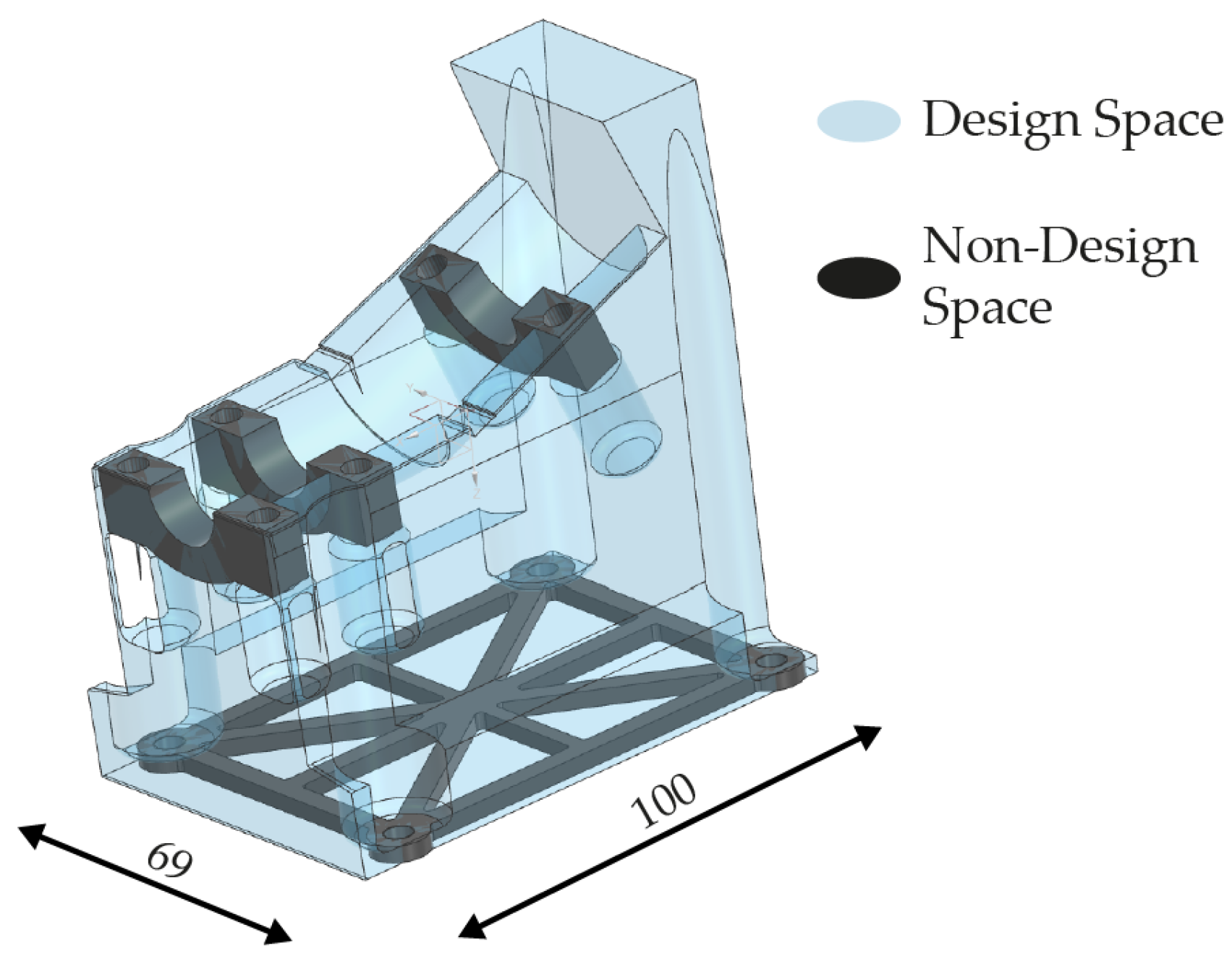
Within the scope of the case study, a steering bracket for a Formula Student team (HAWKS Racing) is optimized with respect to the CMF process. The bracket serves as the housing for the steering components. In addition to supporting these components, it must also withstand the steering loads, which are primarily induced by the driver during vehicle operation. For the optimization, a design space is defined that corresponds to the maximum available installation space of the component. Furthermore, all geometrical features that are mandatory for functionality are specified as non-design space. These include the bearing seats with the associated connection elements, as well as the planar bearing surface required for sintering. The star-shaped design follows a best practice from SBAM, as explained, for example, in [30]. The closed shape with connecting elements to the center of gravity of the bearing surface counteracts distortion caused by friction effects between the component and the contact surface of the furnace. This surface is additionally used to integrate the connection elements necessary for the final assembly of the bracket. The design space, together with the embedded non-design spaces, is shown in Figure 4.
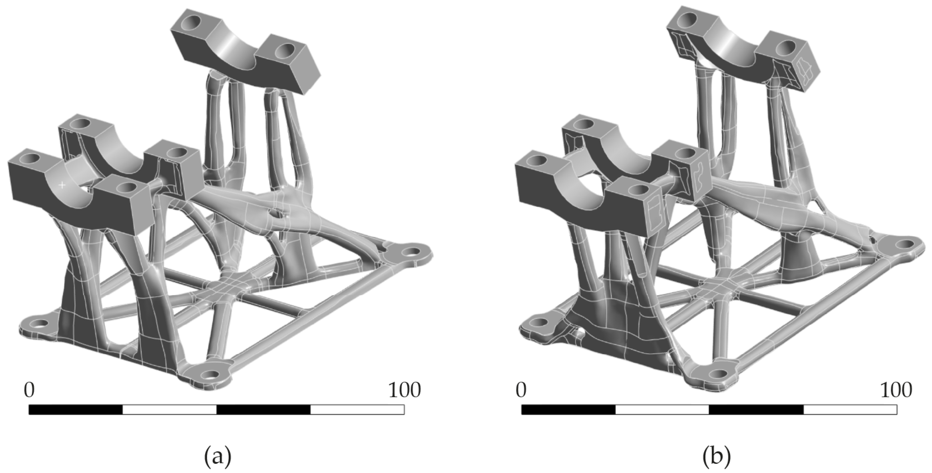
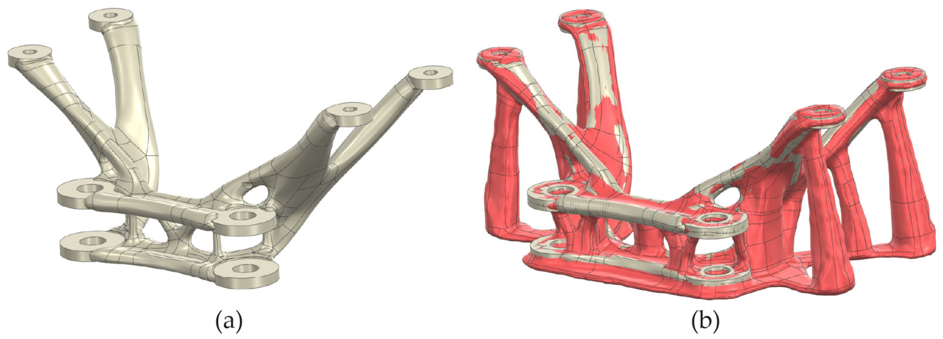
Parallel optimizations are conducted for the design space defined in the as-applied component dimensions (acc. to the previous workflow) and for the same design space in the upscaled state (acc. to the revised workflow). In addition to the sintering load case, which is implemented with a local stress target of 10 kPa, more than ten further load cases are considered. Among these, two particularly critical cases involved forces exceeding 2000 N acting on the bearing seats. For these critical load cases, a local stress target of 850 MPa was applied. The outcomes of the optimizations are presented in Figure 5. Figure 5a illustrates the result for the non-upscaled design space, while Figure 5b shows the result obtained for the upscaled design space. Both geometries correspond to the condition after sintering; the component in Figure 5b was therefore rescaled after optimization to match the intended final dimensions.
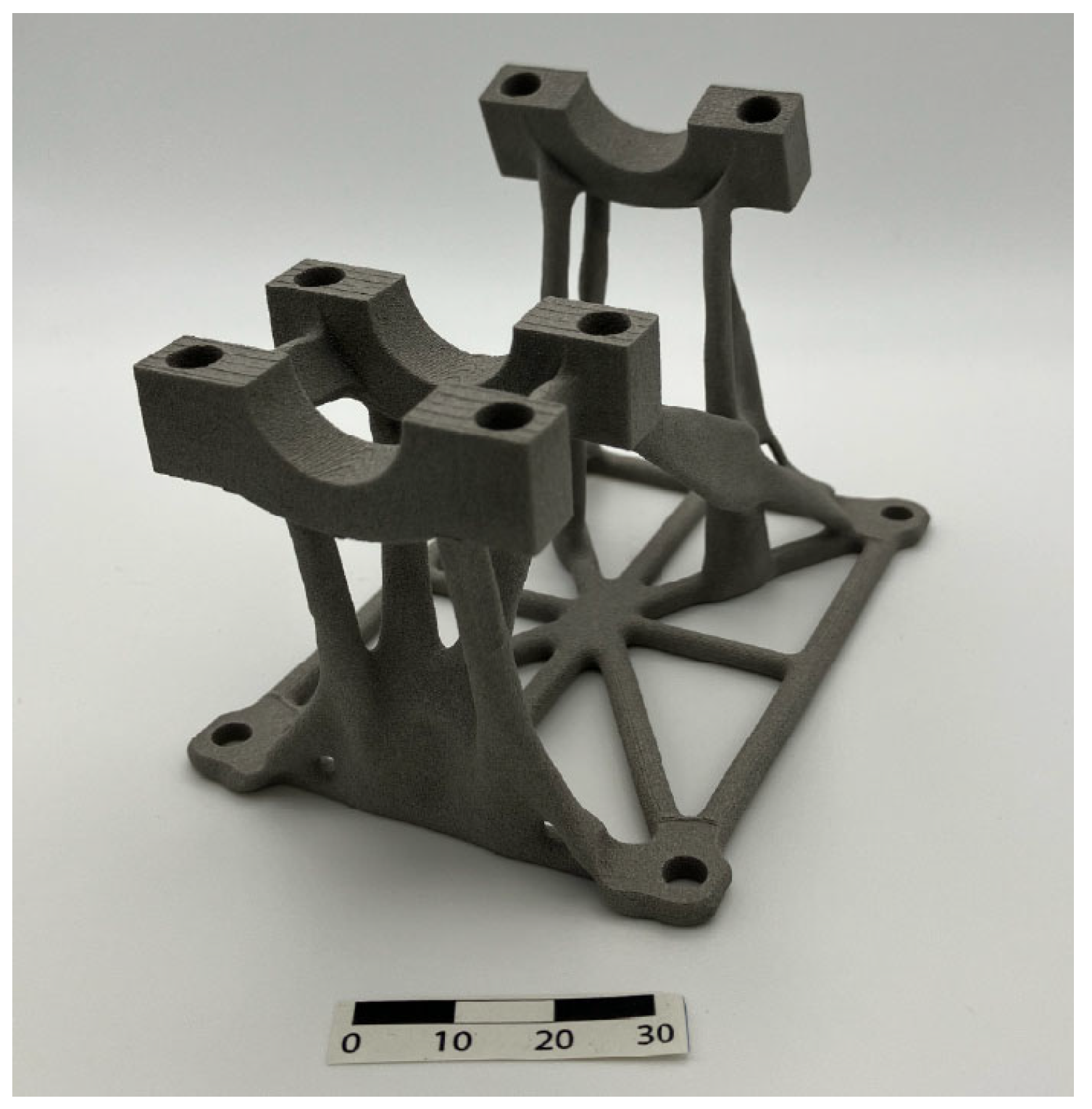
A validation of the resulting geometries was subsequently carried out. For this purpose, the maximum principal stress caused by the dead load of each component was considered. According to [9], this represents the relevant evaluation criterion for the CMF process under investigation. This analysis was performed in the upscaled state, as this is the configuration in which dead-load-induced stresses are critical. In addition, the von Mises equivalent stress was determined for the critical application load case. This evaluation was conducted on the geometries in their final, sintered (i.e., non-upscaled) condition. Furthermore, the mass of each part in the sintered state was determined. The corresponding results are summarized in Table 2. The geometry generated using the revised workflow exhibits 5.9% more mass than the geometry obtained with the previous workflow. However, the revised design not only fulfills the sintering criterion under dead load but also deviates from the stress target of the critical application load case by only 5.1%. By contrast, the component optimized with the former workflow fails to meet the required sintering stress criterion and exceeds the target stress in the critical application case by 47.2%. Although the handling of prescribed and achieved optimization targets must still follow best-practice considerations, optimization in the upscaled state appears to be a promising approach for addressing the sintering load case effectively. The physical sintered bracket, which has been developed via the revised workflow, is shown in Figure 6.

3.2. Optimization of Sinter Supports

In cases where the use of sintering supports is unavoidable, stress-based optimization can be applied to semi-automatically generate such structures. The procedure requires the definition of a design space that contains both the scaled part geometry and the base structure of the support. The base structure can be derived, for instance, from the projected shadow of the part. The process then follows the same logic as outlined in the previous subsection: the part and the defined base are treated as non-design space and remain unchanged during optimization, while the optimization domain serves as the potential support volume. Only the sinter load case is applied in this step.
The resulting geometry consists of both the part and the sintering support. To prepare for manufacturing, the separation of these entities is necessary. This can be achieved using standard CAD software via Boolean operations. To avoid bonding during sintering, the support structures are typically offset at the contact surfaces and coated accordingly. A case study is presented to illustrate the method and provide visualizations of the results.
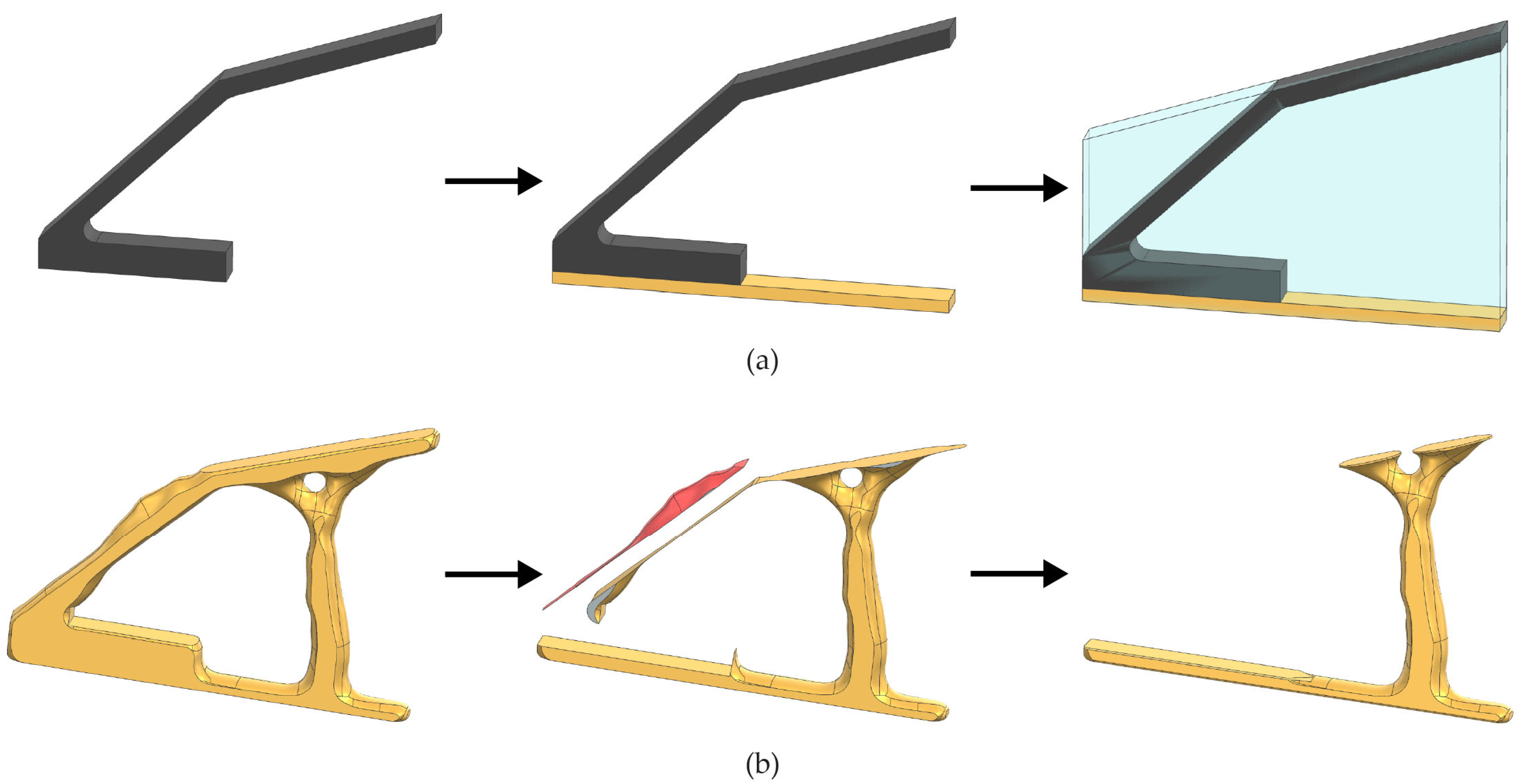
For the case study, a specimen is designed that would not withstand debinding and sintering under its dead load. The intermediate pre-processing workflow steps are illustrated in Figure 7a by means of CAD representations. Due to the designed lever arm, the stresses occurring in the component are excessive and would lead to failure. In the next step, the support base is created. This base must contain sufficient material to prevent failure under the frictional forces generated by the component mass during sintering. For the geometry under consideration, the design of the base is straightforward due to the component’s simple shape. For more complex geometries, a possible approach is to project the shadow curve of the component onto the reference plane and extrude this projection to generate the base. Subsequently, a solid body is generated that encompasses both the component and the support base. This body serves as the design space for the following optimization. The geometry of the component is defined as non-design space and therefore remains unchanged throughout the optimization. The support base is likewise treated as non-design space. As discussed in the previous section on component optimization for SBAM, the bottom of the base is defined as a fixed boundary condition, and gravity is applied. The local stress target is again set to 10 kPa.
Figure 7b illustrates the intermediate steps of the post-processing after optimization. The process begins with the geometry obtained as the direct result of the optimization. From this geometry, the component volume is subtracted, leaving the support structure together with residual artifacts that require removal. In addition, the support–component interfaces, i.e., the surfaces on which the component is positioned during sintering, are adjusted. For the CMF technology with Ti-6Al-4V feedstock considered here, a material offset of 0.25 mm is applied in the surface normal direction. This offset is necessary to ensure subsequent coating of the contact areas on the support. This non-sintering interlayer enables detachment from the support without additional machining after sintering. For Ti-6Al-4V, ceramic material is a popular coating choice [31].
For validation of the virtual results, the components and their corresponding supports were manufactured using the CMF process and subsequently subjected to debinding and sintering. Supports were applied only for a subset of the components. Figure 8 presents photographs of some of the sintered specimens, contrasting those processed without supports (Figure 8a) and those processed with supports (Figure 8b).
However, the approach is not entirely fail-safe. Optimization may not only generate discrete support structures but also produce local thickening of the part itself. Such additional material may be beneficial if the design space and weight constraints allow for increased robustness. Conversely, if the added material is undesirable, it can be removed when separating the part and support. In cases where removal compromises stress targets, further optimization iterations become necessary. This requires manipulation of the design space to prevent material formation in unwanted regions.
The complexity of the part geometry can also pose challenges. For parts with planar surfaces at the support interfaces, Boolean separation is straightforward. In contrast, for parts consisting of multiple freeform surfaces, errors may occur during Boolean operations [32]. This scenario is particularly relevant for geometries derived from optimization algorithms, where freeform features are common. To mitigate these challenges, iterative optimization and the deliberate creation of planar interface regions may be necessary. In cases of highly complex components and support geometries, separation may not be feasible without additional manual intervention. An example of such a case is the bracket shown in Figure 9a. The geometry of the component represents the outcome of topology optimization. However, the bracket was neither provided with geometric features required for sintering, such as a planar bearing surface or a closed bearing contour, nor was it optimized with respect to the stress limits arising from its dead load. Consequently, a sinter support is necessary for manufacturing. Figure 9b illustrates the result of an optimization performed according to the procedure described above. The reddish surfaces represent the volume fraction generated during optimization. While the structure would withstand its dead load during sintering, the support fraction cannot be easily separated from the component. The numerous intersections within the predominantly freeform geometry hinder a straightforward separation of the two parts.
A manual approach for such complex geometries could follow commonly applied procedures established in the context of the SIMP algorithm. As outlined in [33], the optimization result is typically redesigned manually in Computer Aided Design (CAD) after the optimization. In contrast to the bracket example shown in Figure 9, such a redesign would not necessarily rely on freeform surfaces. Instead, it is customary to generate an extrusion of cross-sections along the load paths that can be derived from the optimized structure. The baseplate of the support serves as the starting reference for this extrusion. During redesign, the extrusion must be implemented such that a defined offset between the support and the component is preserved, as this offset is required to allow the subsequent coating of the support surfaces. For support structures needed between two component faces, an insertable structure coated on all contact surfaces may be employed. Alternatively, support-relevant features may also be integrated directly into the component itself. Particularly for surfaces that require machining after sintering due to functional specifications, this latter approach represents a suitable and efficient option. This approach would offer a viable means of manually handling more complex geometries. Since the redesigned geometry represents only a simplified approximation of the optimization results, multiple iterations may be required to ensure compliance with the defined stress limits.
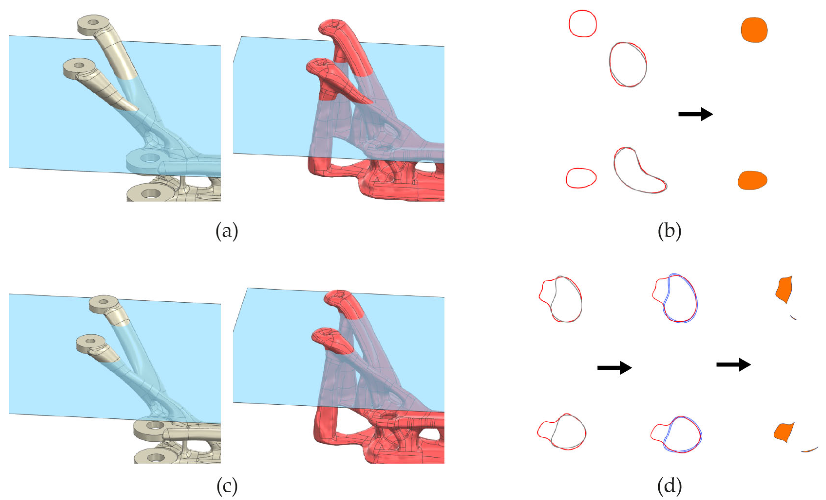
The automated approach is based on the concept developed by [34]. The geometry is divided into a finite number of planes. The intersection curves of the geometry and planes represent the surface of the geometry in the respective plane. In this application, such a decomposition is performed both for the pure component geometry and for the combined geometry of the component and optimized support structure. If the intersection curves of both scenarios are superimposed, the component and support geometry can be distinguished from each other. It should be noted that local thickening of the component geometry may occur during optimization. This thickening is related, among other things, to the surface smoothing that takes place in the MSC Apex GD optimization process. In the current software release (2025.01), the optimization process is convergence-controlled, which could lead to more robust results in this context. A possible procedure for identifying the support geometry would be:
  • Break down the geometries (component and component with support) into planes
  • Derive the intersection curves of geometries and the respective plane
  • Overlay the intersection curves in the respective layer
  • Offset the intersection curve of the pure geometry by the thickness of the support coating
  • Subtract the enclosed area of this modified intersection curve from the area enclosed by the intersection curve of the optimized geometry
Steps three to five must be performed for all planes. The geometry of the support can then be derived from the remaining surfaces in the style of, for example, [34]. This may result in artifacts, which can be handled automatically using defined rules for, for example, minimum wall thicknesses. Figure 10 visualizes the procedure described for two planes of the scenario shown in Figure 9. Figure 10a shows the intersection plane used to generate the intersection curves for the component and the optimized structure. In this plane, the geometries are separated (see Figure 10b). There is no overlap between the component and the support. This results in the marked areas in Figure 10b on the right-hand side as part of the support structure in this plane. Figure 10c shows another intersection plane. It is located at a position where the component and optimized structure are connected, as can be seen in Figure 10d on the left. Figure 10d also shows the results of the subsequent steps: the offset of the component’s intersection curve and the resulting share of the support structure in this plane. Here, also, artifacts can be seen that could be treated by a minimum wall thickness criterion.

3.3. Optimization with Respect to Stiffness

Stiffness can serve as an additional design objective in specific scenarios. For simple cross-sections, stiffness may be expressed quantitatively via the moment of inertia. For more complex geometries, stiffness is more generally defined as the resistance to deformation caused by external influences [35]. However, stiffness as an aspect of the design for manufacturing for sintering technologies is neither found in the context of conventional processes [36] nor in the context of sinter-based AM [30]. In the optimization framework, stiffness is implemented via local displacement targets, each defined for a specific load case. The influence of stiffness on sintering-induced deformation under gravitational load is investigated using test specimens. In order to design suitable specimens, the requirements for them must be clarified. Possible approaches are then derived from these requirements. The requirements and the respective approaches are listed in Table 3.
A possible combined solution for these approaches is described in the following: a specimen with few structural elements is suitable for investigating an instability problem, such as the buckling of a beam. The specimen structure is modeled after that of a fixed beam. This beam is vertical, which means that the weight force acts on the beam in the axial direction due to gravity. The situation is analogous to Euler case 1, as described in [37]. A regular geometry that can be considered in the context of the machining allowance for buckling is a bore, i.e., a hollow cylinder. In order to enable evaluation with as few 3D scanning restrictions as possible, a half-hollow cylinder is considered. This half-hollow cylinder is attached to a base plate, which also serves as a reference for determining the deformation during the measurements. The relationship between tolerancing and the buckling phenomenon can be addressed through the requirement of maintaining a horizontal bore orientation. Such a requirement typically arises in practical applications from the tolerance specification of the bore axis parallelism with respect to a reference surface. In the investigated case, this reference surface corresponds to the bearing surface of the respective specimen, i.e., the lower surface of the base plate. A technical sketch of the specimen is shown in Figure 11. The bearing surface serves both as the datum feature for tolerance definition according to [38] and as the reference for evaluating the deformation of the specimen during measurement. The entry min in the tolerance field does not comply with the standard. In this context, it means that a minimum deviation in parallelism is the desired goal when designing components for SBAM.
The tilt angle of the cylinder axis is selected as the clear variable for evaluation. This value is measured both in the green state, i.e., immediately after printing, and after debinding and sintering, i.e., in the sintered state (s. Figure 12). This means that the following represents the angle of inclination that the specimen experiences during subsequent processing:
α d e l t a = α s i n t e r e d α g r e e n
The measured angle can also be used to derive an order of magnitude for the parallelism achievable in the “as sintered” state. The vertical distance between the two bore axis end points can be used to evaluate this parallelism. This distance can be calculated using the following:
z = s i n ( α d e l t a ) · l c y l i n d e r
where lcylinder is the length of the cylinder and, thereby, the length of the bore hole after sintering. This is only valid if the cylinder does not warp. This is not expected to occur due to the continuous support in the axial direction.
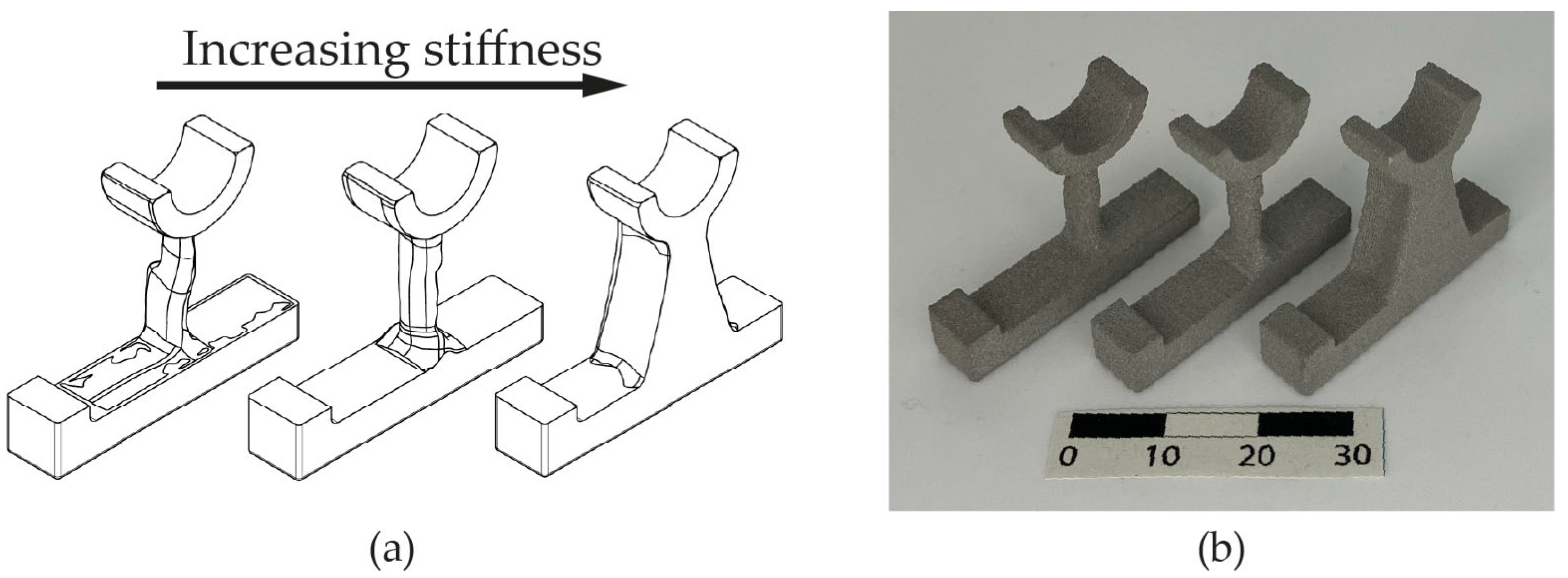
For the investigations, three configurations are made, corresponding to low, medium, and high stiffness in the direction of gravity (s. Figure 13). The stiffness is controlled by the geometry of the cylinder’s attachment to the base plate, which results from optimization processes with a virtual load case. Within this load case, a force of 1000 N is applied in the direction of gravity perpendicular to the cylinder. In addition to this, a displacement constraint regarding the direction of gravity is implemented for this load case. Similar to the specified stress targets, the displacement constraints are not necessarily achieved in the optimization. Therefore, the displacements of the optimized structures occurring under the virtual load are examined using finite element analysis according to the setup in Section 2.4. The specimen geometries are determined based on the displacements under the virtual loads identified in the FEA. The experimental configuration, including the corresponding displacement values with respect to the virtual load, is shown in Table 4.
The values from the measurements are stated in Appendix A. The statistical values from the measurements are shown in Table 4. For the angle, the mean values and standard deviations are given. The mean values for the vertical distance between the cylinder endpoints were calculated and are stated as well. These values demonstrate the correlation between stiffness and deformation behavior during sintering. The inclination of the cylinders decreases significantly with increasing stiffness. While the dispersion of the deviation is relatively similar for low and medium stiffness configurations, the deviations for the high stiffness configuration are significantly lower. The findings highlight the potential of stiffness-based optimization to complement stress-based approaches in ensuring the dimensional stability of SBAM components. Statistical significance is confirmed by applying the analysis of variance (ANOVA) method. This results in a p-value of 0.000 and an F-value of 32.16 for the inclination of the cylinder.

4. Discussion

In this work, various optimization approaches were discussed with regard to their potential for SBAM, whereby the stress-based optimization approach comprising the BESO method combined with a hard-kill option has proven to be the most suitable. This approach was applied in various scenarios to examine potential use cases. The procedure for component optimization towards sinterability described in [9] was further developed. The revised methodology applies all load cases directly to the upscaled green-part geometry. This adjustment avoids the non-linear scaling discrepancies of dead load stresses that previously required additional post hoc checks and could trigger iterative optimization loops. Based on the conducted case study, it was shown that this revised approach not only has a positive effect on sinterability but also improves the mechanical performance of the component with respect to the remaining load cases. Although these findings are primarily derived from case studies, the underlying mechanisms of stress-based optimization suggest that the revised approach can generally support robust component design. A critical aspect of this optimization method is its exclusive focus on loads induced by gravity. Component failure, however, may also result from contact conditions or other stresses occurring during sintering. Optimization against dead-load-induced stresses should therefore be understood as a necessary but not sufficient criterion for reliable part design [9]. In addition, there is potential for improvement in the definition of stress targets. While the employed algorithm applies von Mises equivalent stress as the optimization criterion, the use of maximum principal stress would be more suitable for the CMF process. Optimization studies based on such stress targets have been presented, for example, in [39]. For technologies such as MFFF, an optimization based on normal stresses, as also applied in [27] for evaluation purposes, would be more appropriate. Generally, this optimization approach only considers the static load caused by the dead load of the component. This static load triggers deformation and failure processes during debinding and sintering. These processes themselves are not taken into account in the optimization. Therefore, optimization with regard to the sintering load case should be interpreted as a necessary criterion, not as a sufficient criterion, as also discussed in [9]. Sufficient optimization solutions should take into account the dynamic processes during processing. So-called sintering stresses and geometric deformation affect the component and are drivers for component failure. Coupling the optimization with a process simulation as described in [40] is a conceivable approach. This approach takes into account the stresses and shape changes during debinding and sintering that occur due to thermal and microstructural processes.
Furthermore, a methodology for optimization-based, semi-automated design of sinter supports was introduced. This approach also relies on stress-based optimization, including the implementation of the sinter load case, analogous to component optimization. This method offers considerable potential for time savings due to the algorithm-driven design of support structures. Nevertheless, several practical challenges remain, particularly in separating freeform surfaces during post-processing. Formally, it should also be noted that the optimization delivers a single, unified structure as output. In real scenarios, however, the result consists of two separate components between which contact interactions occur, meaning that the mechanical conditions differ from those represented in the optimization.
As a third aspect, a study was conducted to investigate the influence of structural stiffness on deformation during debinding and sintering. For this purpose, specimen geometries were generated using stress-based optimization. In addition to stress targets, different displacement constraints in the direction of gravity were implemented, resulting in specimens with varying stiffness in this direction. The investigations revealed that higher structural stiffness in the direction of gravity reduces deformation in this direction during debinding and sintering. Due to buckling-related effects, tilting of the specimens led to dimensional deviations of up to 0.17 mm in the case of low stiffness, while specimens with high stiffness exhibited deviations as small as 0.01 mm. These findings demonstrate that optimizing components with respect to stiffness in the direction of gravity holds significant potential for SBAM. In particular, processes whose parts are prone to large deformations during post-processing, such as MFFF [9], can benefit from the implementation of such boundary conditions. The implementation effort for these boundary conditions is low. Moreover, higher stiffness not only reduces deformations but also lowers stresses in the corresponding load case [35]. Since the focus is on structural stiffness in the direction of gravity, this effect may also positively influence stresses induced by the dead load of the component. A current limitation is that stiffness optimization must rely on virtual load cases, as the optimization operates with sintered material properties, where the effect of gravity alone is not significant. The loads to be used within these virtual load cases have to be determined iteratively. The goal of implementing these loads in combination with displacement constraint is to achieve a higher stiffness of the component with respect to the direction of gravity.

Supplementary Materials

The following supporting information can be downloaded at: https://www.mdpi.com/article/10.3390/app152212198/s1.

Author Contributions

Conceptualization, D.S.; methodology, D.S.; software, D.S.; validation, D.S., J.B. and J.T.; formal analysis, D.S.; investigation, D.S.; resources, D.S.; data curation, D.S.; writing—original draft preparation, D.S. and J.B.; writing—review and editing, D.S., J.B. and J.T.; visualization, D.S.; supervision, J.T.; project administration, J.T.; funding acquisition, J.T. All authors have read and agreed to the published version of the manuscript.

Funding

The project “Development of sinter-based generative process routes for aluminum and titanium alloys for topology-optimized lightweight components for the mobility sector (SIGNAL)” is funded by the Federal Ministry for Economic Affairs and Energy (BMWE, German Federal Ministry) in the Lightweight Technology Transfer Program (TTP LB) under the funding code 03LB2060 and supervised by Project Management Jülich (PtJ).

Institutional Review Board Statement

Not applicable.

Informed Consent Statement

Not applicable.

Data Availability Statement

Data is contained within the article or Supplementary Materials.

Acknowledgments

The authors would like to express their sincere thanks to Element22 GmbH for their support in manufacturing (3D printing, debinding, and sintering) the components examined in this study. During the preparation of this manuscript, the authors used GPT-5 for the purposes of translating parts of the text. The authors have reviewed and edited the output and take full responsibility for the content of this publication.

Conflicts of Interest

The authors declare no conflicts of interest.

Abbreviations

The following abbreviations are used in this manuscript:
BESOBi-directional Evolutionary Structural Optimization
CADComputer-Aided Design
CMFCold Metal Fusion
DEDDirected Energy Deposition
ESOEvolutionary Structural Optimization
FEAFinite Element Analysis
LPBFLaser Powder Bed Fusion
MBJMetal Binder Jetting
MFFFMetal Fused Filament Fabrication
MIMMetal Injection Molding
PMPowder Metallurgy
SBAMSinter-based Additive Manufacturing
SIMPSolid Isotropic Material with Penalization
SLSSelective Laser Sintering

Appendix A

Table A1. Measured values for the tilt of the cylinder of stiffness specimens.
ID α g r e e n α s i n t e r e d α d e l t a α d e l t a ¯
Low_16.718.531.821.35
Low_24.555.951.39
Low_34.545.410.87
Low_47.519.161.65
Low_55.826.590.77
Low_64.125.321.20
Low_73.835.161.32
Low_86.308.071.77
Medium_14.194.610.420.77
Medium_23.434.370.94
Medium_31.652.180.53
Medium_43.524.731.21
Medium_56.096.260.17
Medium_6 *8.004.08−3.92
Medium_73.264.200.94
Medium_84.575.741.17
High_11.391.430.030.09
High_20.750.760.01
High_31.080.84−0.24
High_42.012.430.42
High_51.051.300.25
High_60.670.770.10
High_70.720.59−0.13
High_81.932.220.28
* As these values are statistically proven extreme outliers that cannot be explained, they have been excluded from further statistical analysis.

References

  1. Gibson, I.; Rosen, D.; Stucker, B.; Khorasani, M. Additive Manufacturing Technologies; Springer International Publishing: Cham, Switzerland, 2021; ISBN 978-3-030-56126-0. [Google Scholar]
  2. Presciutti, A.; Gebennini, E.; Liberti, F.; Nanni, F.; Bragaglia, M. Comparative Life Cycle Assessment of SLS and mFFF Additive Manufacturing Techniques for the Production of a Metal Specimen. Materials 2023, 17, 78. [Google Scholar] [CrossRef] [PubMed]
  3. Mostafaei, A.; Elliott, A.M.; Barnes, J.E.; Li, F.; Tan, W.; Cramer, C.L.; Nandwana, P.; Chmielus, M. Binder Jet 3D Printing—Process Parameters, Materials, Properties, Modeling, and Challenges. Prog. Mater. Sci. 2021, 119, 100707. [Google Scholar] [CrossRef]
  4. Zhu, B.; Li, R.; Yuan, T.; Li, W.; Cai, D.; Kang, N. Metal Binder Jetting Additive Manufacturing: An Overview of the Process, Materials and Reinforcement Methods. J. Alloys Compd. 2025, 1037, 182196. [Google Scholar] [CrossRef]
  5. Paudel, B.J.; Conover, D.; Lee, J.-K.; To, A.C. A Computational Framework for Modeling Distortion during Sintering of Binder Jet Printed Parts. J. Micromech. Mol. Phys. 2021, 06, 95–102. [Google Scholar] [CrossRef]
  6. Paudel, B.J.; Deng, H.; To, A.C. A Physics-Based Data-Driven Distortion Compensation Model for Sintered Binder Jet Parts Considering Size Effects. Addit. Manuf. 2023, 68, 103517. [Google Scholar] [CrossRef]
  7. Li, Z.-J.; Xiao, P.; Dai, H.-L.; Yao, Y.; Luo, W.-F. Modelling of Geometrical Deformation and Compensation during Sintering of Binder Jetting. Virtual Phys. Prototyp. 2025, 20, e2443958. [Google Scholar] [CrossRef]
  8. Gözüküçük, F.; Telgkamp, J.; Scharowsky, T.; Tenelsen, C. Sintering Simulation and Validation for the Sinter-Based Fused Filament Fabrication Process Route. Prog. Addit. Manuf. 2025, 10, 10091–10109. [Google Scholar] [CrossRef]
  9. Stachg, D.; Marter, T.; Telgkamp, J. Green Part Properties as Design Driver for “First Time Right” within Sinter-Based Additive Manufacturing Introduced on the Examples of Cold Metal Fusion and Metal FFF. RTe J. 2025. [Google Scholar] [CrossRef]
  10. Raether, F.; Seifert, G.; Ziebold, H. Simulation of Sintering across Scales. Adv. Theory Simul. 2019, 2, 1900048. [Google Scholar] [CrossRef]
  11. Tyflopoulos, E.; Steinert, M. Topology and Parametric Optimization-Based Design Processes for Lightweight Structures. Appl. Sci. 2020, 10, 4496. [Google Scholar] [CrossRef]
  12. Rosso, S.; Uriati, F.; Grigolato, L.; Meneghello, R.; Concheri, G.; Savio, G. An Optimization Workflow in Design for Additive Manufacturing. Appl. Sci. 2021, 11, 2572. [Google Scholar] [CrossRef]
  13. Kaschube, D.; Pawlowitz, T.; Solterbeck, C.-H.; Schloesser, J.; Malekan, M.; Bohlmann, B. Fatigue Behavior of Ti-6Al-4 V Alloy Manufactured by Cold Metal Fusion. Fatigue Fract. Eng. Mater. Struct. 2024, 47, 647–661. [Google Scholar] [CrossRef]
  14. Munsch, M. Reduzierung von Eigenspannungen und Verzug in der Laseradditiven Fertigung. Ph.D. Thesis, Technische Universität Hamburg, Hamburg, Germany, 2013. [Google Scholar]
  15. Shen, F.; Zhu, W.; Zhou, K.; Ke, L.-L. Modeling the Temperature, Crystallization, and Residual Stress for Selective Laser Sintering of Polymeric Powder. Acta Mech. 2021, 232, 3635–3653. [Google Scholar] [CrossRef]
  16. Banerjee, S.; Joens, C.J. Debinding and Sintering of Metal Injection Molding (MIM) Components. In Handbook of Metal Injection Molding; Elsevier: Amsterdam, The Netherlands, 2012; pp. 133–180. ISBN 978-0-85709-066-9. [Google Scholar]
  17. Blunk, H.; Seibel, A. Reduction of Sintering Distortion in Metal Binder Jetting: Measuring Friction under Sintering Conditions. J. Jpn. Soc. Powder Powder Metall. 2025, 72, S1475–S1479. [Google Scholar] [CrossRef]
  18. Blunk, H.; Huber, N. Resource-Efficient Sintering Supports for the Metal Binder Jetting Process. In Innovative Product Development by Additive Manufacturing 2022; Lachmayer, R., Bode, B., Kaierle, S., Eds.; Springer International Publishing: Cham, Switzerland, 2023; pp. 110–120. ISBN 978-3-031-27260-8. [Google Scholar]
  19. Meng, L.; Zhang, W.; Quan, D.; Shi, G.; Tang, L.; Hou, Y.; Breitkopf, P.; Zhu, J.; Gao, T. From Topology Optimization Design to Additive Manufacturing: Today’s Success and Tomorrow’s Roadmap. Arch. Computat. Methods Eng. 2020, 27, 805–830. [Google Scholar] [CrossRef]
  20. Reiher, T.; Deppe, G.; Maasjost, L.; Yu, X. Topology Optimization of Submodels within MSC Nastran Assembly Context Using a Voxel-Based Engineering Approach. In Proceedings of the NAFEMS World Congress 2025, Salzburg, Austria, 19–22 May 2025. [Google Scholar]
  21. Sauer, A. Bionik in der Strukturoptimierung: Praxishandbuch für Ressourceneffizienten Leichtbau; Vogel Business Media: Würzburg, Germany, 2018; ISBN 978-3-8343-3381-0. [Google Scholar]
  22. Huang, X.; Xie, Y.-M. A Further Review of ESO Type Methods for Topology Optimization. Struct. Multidisc. Optim. 2010, 41, 671–683. [Google Scholar] [CrossRef]
  23. Abbey, T. Topology Optimization (Part 2)—FE Training. Available online: https://fetraining.net/topology-optimization-part-2/ (accessed on 26 September 2025).
  24. ASTM International B988-18R22; Standard Specification for Powder Metallurgy (PM) Titanium and Titanium Alloy Structural Components. ASTM: West Conshohocken, PN, USA, 2022.
  25. Ibhadode, O.; Zhang, Z.; Sixt, J.; Nsiempba, K.M.; Orakwe, J.; Martinez-Marchese, A.; Ero, O.; Shahabad, S.I.; Bonakdar, A.; Toyserkani, E. Topology Optimization for Metal Additive Manufacturing: Current Trends, Challenges, and Future Outlook. Virtual Phys. Prototyp. 2023, 18, e2181192. [Google Scholar] [CrossRef]
  26. El Khadiri, I.; Zemzami, M.; Nguyen, N.-Q.; Abouelmajd, M.; Hmina, N.; Belhouideg, S. Topology Optimization Methods for Additive Manufacturing: A Review. Int. J. Simul. Multidisci. Des. Optim. 2023, 14, 12. [Google Scholar] [CrossRef]
  27. Forward AM Debinding Simulation Guidelines for 3D Printed Parts Using Ultrafuse® 316L. Available online: https://forward-am.com/material-portfolio/ultrafuse-filaments-for-fused-filaments-fabrication-fff/metal-filaments/ultrafuse-316l/ (accessed on 1 September 2025).
  28. Tang, T.; Wang, L.; Zhu, M.; Zhang, H.; Dong, J.; Yue, W.; Xia, H. Topology Optimization: A Review for Structural Designs Under Statics Problems. Materials 2024, 17, 5970. [Google Scholar] [CrossRef]
  29. Hexagon AB MSC Apex GD—Stresses, Failure Criteria & Resolution Levels. Available online: https://amendate.atlassian.net/wiki/spaces/ApexGD/pages/3776185310/Stresses+Failure+Criteria+Resolution+Levels (accessed on 15 September 2025).
  30. Schmidt-Lehr, M.; Führer, T. Design Guideline for Sinter-Based Additive Manufacturing; AMPOWER Insights: Hamburg, Germany, 2021. [Google Scholar]
  31. Devine, E.; Lester, M.; McElroy, T.; Valenzuela, T.; LePage, W. Mechanical Characterization of Additive-Manufactured Ti-6Al-4V Processed via Bound Metal Deposition. Exp. Mech. 2025, 65, 573–596. [Google Scholar] [CrossRef]
  32. Urick, B.; Marussig, B.; Cohen, E.; Crawford, R.H.; Hughes, T.J.R.; Riesenfeld, R.F. Watertight Boolean Operations: A Framework for Creating CAD-Compatible Gap-Free Editable Solid Models. Comput.-Aided Des. 2019, 115, 147–160. [Google Scholar] [CrossRef]
  33. Al-Zuhairi, A.; Nouzille, D.; Teutsch, R. Systematical Redesign Method for Topology Optimized Results Using 3D-Printing. Discov. Mech. Eng. 2023, 2, 11. [Google Scholar] [CrossRef]
  34. Boissonnat, J.-D. Shape Reconstruction from Planar Cross Sections. Comput. Vis. Graph. Image Process. 1988, 44, 1–29. [Google Scholar] [CrossRef]
  35. Klein, B.; Gänsicke, T. Leichtbau-Konstruktion: Dimensionierung, Strukturen, Werkstoffe und Gestaltung; Springer Fachmedien Wiesbaden: Wiesbaden, Germany, 2019; ISBN 978-3-658-26845-9. [Google Scholar]
  36. Heaney, D.F. Designing for Metal Injection Molding (MIM). In Handbook of Metal Injection Molding; Elsevier: Amsterdam, The Netherlands, 2012; pp. 29–49. ISBN 978-0-85709-066-9. [Google Scholar]
  37. Mittelstedt, C. Buckling of Beams, Plates and Shells; Springer: Berlin/Heidelberg, Germany, 2024; ISBN 978-3-662-69095-6. [Google Scholar]
  38. DIN EN ISO 1101:2017; Geometrical Product Specifications (GPS)—Geometrical Tolerancing—Tolerances of Form, Orientation, location and Run-Out (ISO 1101:2017). Deutsches Institut für Normung: Berlin, Germany, 2017. [CrossRef]
  39. Giraldo-Londoño, O.; Russ, J.B.; Aguiló, M.A.; Paulino, G.H. Limiting the First Principal Stress in Topology Optimization: A Local and Consistent Approach. Struct. Multidisc. Optim. 2022, 65, 254. [Google Scholar] [CrossRef]
  40. Sadeghi Borujeni, S.; Shad, A.; Abburi Venkata, K.; Günther, N.; Ploshikhin, V. Numerical Simulation of Shrinkage and Deformation during Sintering in Metal Binder Jetting with Experimental Validation. Mater. Des. 2022, 216, 110490. [Google Scholar] [CrossRef]
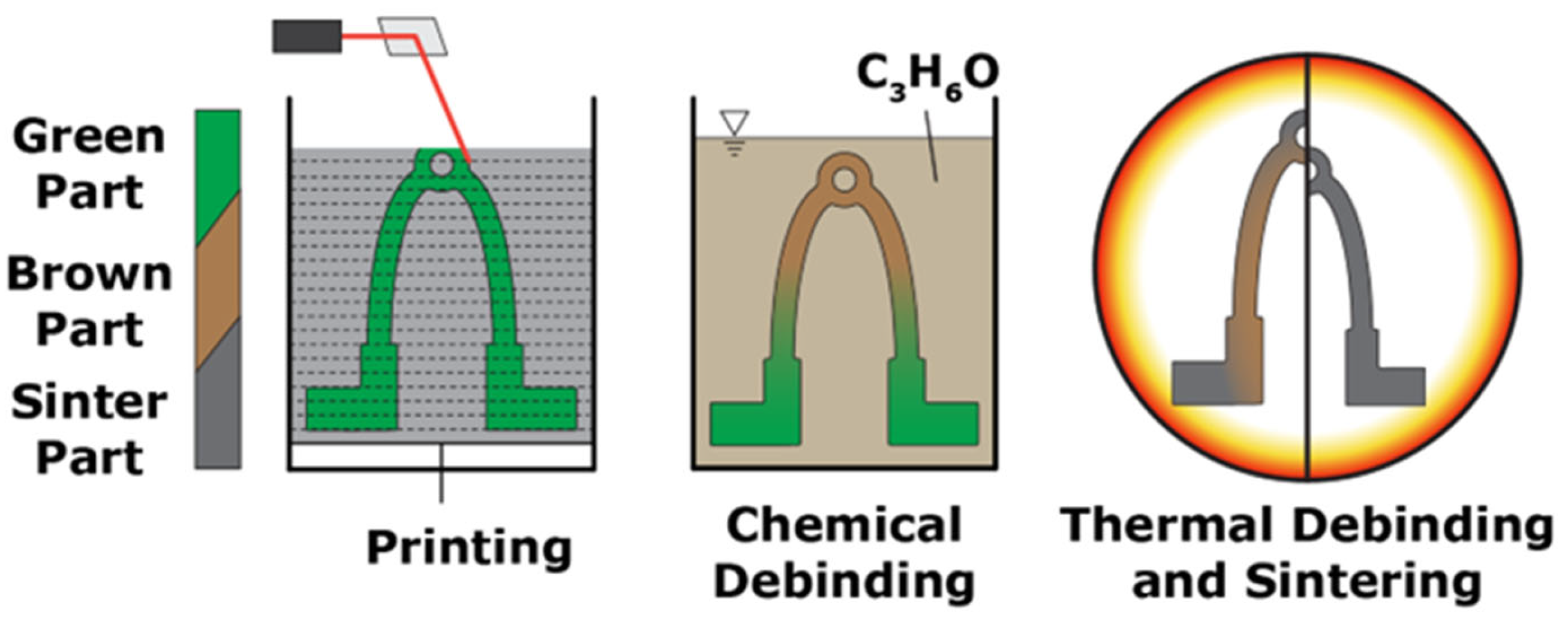
Figure 1. Main process steps within CMF for Ti-6Al-4V [9].
Applsci 15 12198 g001
Figure 2. Implementation of the sinter load case for optimization.
Applsci 15 12198 g002
Figure 3. Previous and revised optimization workflow.
Applsci 15 12198 g003
Figure 4. Design space for the Formula Student’s steering bracket.
Applsci 15 12198 g004
Figure 5. Optimized geometry based on (a) the previous workflow and (b) the revised workflow.
Applsci 15 12198 g005
Figure 6. Sintered physical bracket.
Applsci 15 12198 g006
Figure 7. (a) Pre-processing of support optimization; (b) post-processing of support optimization.
Applsci 15 12198 g007
Figure 8. Sintered physical components (a) processed without support and (b) processed utilizing the optimized support.
Applsci 15 12198 g008
Figure 9. (a) Bracket; (b) Bracket with additional optimized structures.
Applsci 15 12198 g009
Figure 10. (a) Intersection plane with respect to component and optimized structure; (b) resulting intersection curves and resulting areas of support structure within this plane; (c) different intersection plane with respect to component and support structure; (d) resulting intersection curves, addition of component intersection curve’s offset, and resulting areas of support structure within this plane.
Applsci 15 12198 g010
Figure 11. Sketch of specimen, including tolerancing for evaluation.
Applsci 15 12198 g011
Figure 12. Angle of specimen in different states.
Applsci 15 12198 g012
Figure 13. Specimens with differently configured stiffness regarding the gravitational direction. (a) Drawings. (b) Sintered components.
Applsci 15 12198 g013
Table 1. Chemical composition of sintered material.
Alloying Elements in Percent by Weight (%)
TiAlVOFeCN
Low5.5–6.753.5–4.5≤0.30≤0.30≤0.05≤0.05
Table 2. Comparison of optimized geometries.
ComponentStress with Respect to
Dead Load
Stress with Respect to
Critical Load Case
Mass
Previous Workflow21.3 kPa1251.1 MPa116.6 g
Revised Workflow16.8 kPa893.4 MPa123.5 g
Table 3. Requirements regarding specimens for stiffness investigation.
RequirementApproach
Low material consumptionSpecimens with few structural elements
Deformation/error must be clearly evaluableRegular/non-freeform geometry as the evaluation object
Results should be evaluable in a practical contextEvaluation context:
tolerancing
Table 4. Results for stiffness specimens.
ConfigurationResults
StiffnessDisplacement Under Virtual Load (mm) α d e l t a ¯ (°)SD (°) z ¯ (mm)
Low0.101.350.390.16
Medium0.050.770.400.09
High0.010.090.220.01
Disclaimer/Publisher’s Note: The statements, opinions and data contained in all publications are solely those of the individual author(s) and contributor(s) and not of MDPI and/or the editor(s). MDPI and/or the editor(s) disclaim responsibility for any injury to people or property resulting from any ideas, methods, instructions or products referred to in the content.