Article

Study and Application of a Pilot-Tunnel-First Method for Rapid Excavation of Large-Span Soft Rock Tunnels

1
State Key Laboratory of Hydroscience and Engineering, Tsinghua University, Beijing 100084, China
2
State Key Laboratory for Tunnel Engineering, China University of Mining and Technology (Beijing), Beijing 100083, China
3
Municipal Engineering Co., Ltd., China Railway 20th Group Corporation, Lanzhou 730000, China
4
China Coal Research Institute, Beijing 100013, China
5
State Key Laboratory of Intelligent Construction and Healthy Operation and Maintenance of Deep Underground Engineering, University of Mining and Technology, Xuzhou 221008, China
*
Authors to whom correspondence should be addressed.
Appl. Sci. 2025, 15(22), 12194; https://doi.org/10.3390/app152212194
Submission received: 13 October 2025 / Revised: 6 November 2025 / Accepted: 13 November 2025 / Published: 17 November 2025

Abstract

The rapid development of transportation infrastructure in challenging geological regions necessitates innovative tunneling methods that balance efficiency, safety, and cost. This study addresses the critical construction bottleneck of large-span soft rock tunnels under high ground stress, where conventional methods often lead to unacceptable delays. Focusing on a 24.53 m span railway tunnel in southwest China, we present the significant engineering application of a “pilot-tunnel-first” method as a strategic solution to stringent schedule pressures. The core innovation lies not only in the adoption of a large 13.2 m wide pilot tunnel but also in a synergistically enhanced support system, featuring elongated bolts (6 m and 12 m) and strengthened steel arches. Numerical simulations and field validation confirmed that this optimized approach achieves a stability comparable to the traditional double-side drift method while dramatically accelerating progress. The successful implementation shortened the construction period by 1.96 months for a key 123 m section, with a manageable cost increase of approximately Chinese Yuan (CNY) 782,000, thereby ensuring the timely opening of the entire tunnel. The primary significance of this research is to provide a proven and practical technical strategy for overcoming similar soft rock tunneling challenges where project timelines are paramount, offering a substantial value for the design and construction of modern infrastructure under complex constraints.

1. Introduction

With the rapid economic development of China and guided by the philosophy that “building roads comes before prosperity,” the transportation network in the southwestern region of the country has been continuously expanding [1,2,3]. Located within a tectonic compression zone of the Eurasian Plate and characterized by numerous valleys, this region relies heavily on tunnels and bridges for its railway and highway systems. As a result, there is an increasing number of deep-buried extra-long railway tunnels constructed under challenging geological conditions [4,5,6]. Factors such as high ground stress caused by large burial depths restrict the development of tunnel construction. The “three highs and one disturbance” (high ground stress, high ground temperature, high groundwater pressure, and excavation disturbance) hinder human exploration of underground space [7,8,9,10]. When tunnel excavation is carried out under soft rock conditions, it is prone to inducing accidents such as the large deformation of surrounding rock and roof collapse, resulting in construction suspension [11,12,13]. In this regard, many scholars have conducted targeted research and developed a series of soft rock control measures. Sun Jun et al. discussed the nonlinear rheological behavior of tunnels surrounding rock under high in situ stress, laying a theoretical foundation for the optimization of tunnel structural design [14]. Subsequently, they investigated the mechanical characteristics of squeezing large deformations in soft rock tunnels under high in situ stress conditions and applied this theory to study large deformation issues in a railway tunnel [15]. Li Shucai et al. utilized the theory of elastoplastic small strain and large deformation of rocks to analyze the stability of a 10 m span tunnel in Taiwan, providing an effective basis for construction in that region [16]. Soft rock tunnel construction should emphasize time–space effects, and a timely application of rock bolts and steel arch support can effectively restrain the rheological properties of soft rock. After the initial support is applied, secondary lining should be implemented at an appropriate time to withstand the long-term rheological pressure of the surrounding rock [17,18]. From the above analysis, it can be concluded that the use of rock bolts and lining for soft rock tunnel support is an effective means to ensure tunnel safety and stability [19,20,21]. Additionally, yielding rock bolts and arch supports with pressure-relief functionality have been developed and have achieved good application results in relevant engineering projects [22,23].
The design and construction of tunnel engineering are complex and nonlinear. With the development of computers, numerical simulation methods have gradually been applied to tunnel engineering construction. Their advantage is that they can truly reproduce the model size and actual parameters of tunnels, surrounding rocks, and support materials [24,25]. Zhu Hehua et al. used finite element analysis to conduct model tests and numerical simulation analysis on soft and broken rock mass tunnels under variable burial depths, and the results were consistent [26]. Xu Qianwei et al. used physical model tests and numerical simulation methods to analyze the progressive failure process and stress-deformation characteristics of the surrounding rocks of cross-fault tunnels, and the calculation results of the two methods were similar [27]. Su Xiaokun et al. conducted research on the boundary range of the numerical simulation for tunnel excavation, and the results showed that taking three times the span of tunnel excavation as the boundary width is more appropriate [28].
In the past, extensive research has been conducted both domestically and internationally on controlling large deformations in soft rock. Generally, two approaches are adopted. One method involves reducing the construction progress and minimizing the dimensions of the excavation cross-section, such as the CD method and CRD method [29,30]. This approach ensures a relatively high construction stability but results in a slower construction efficiency. The other method involves the use of specialized construction equipment, such as energy-absorbing large deformation bolts and cable supports [31,32]. However, this method entails higher costs. From the above, it is evident that controlling large deformations in soft rock inevitably involves compromises in terms of either construction efficiency or economic considerations.
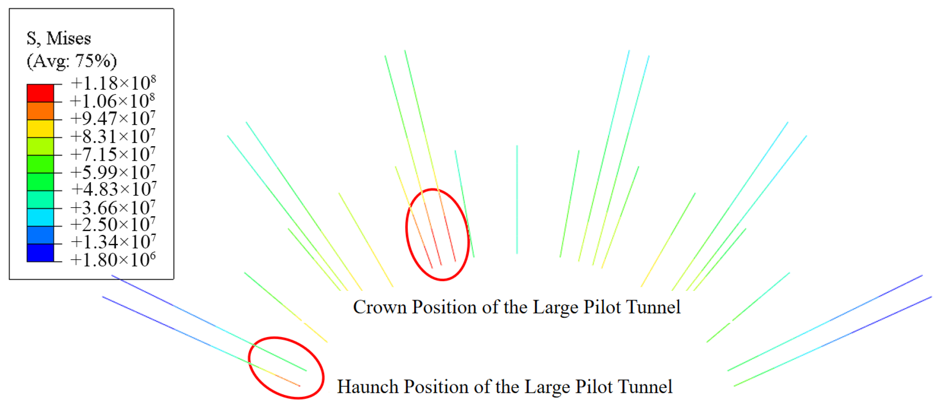
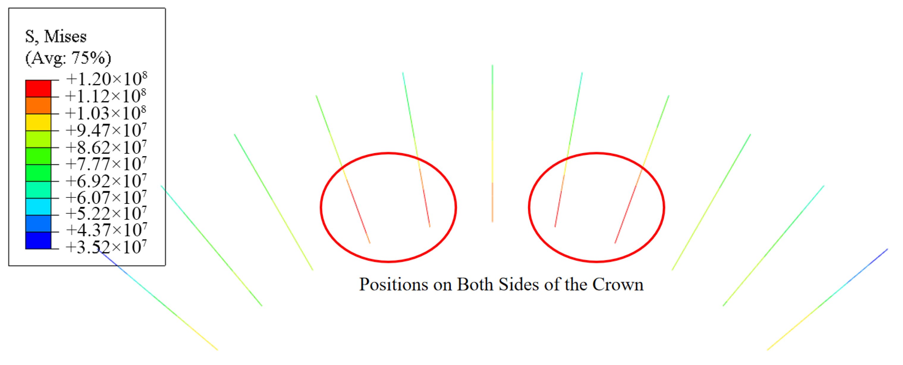
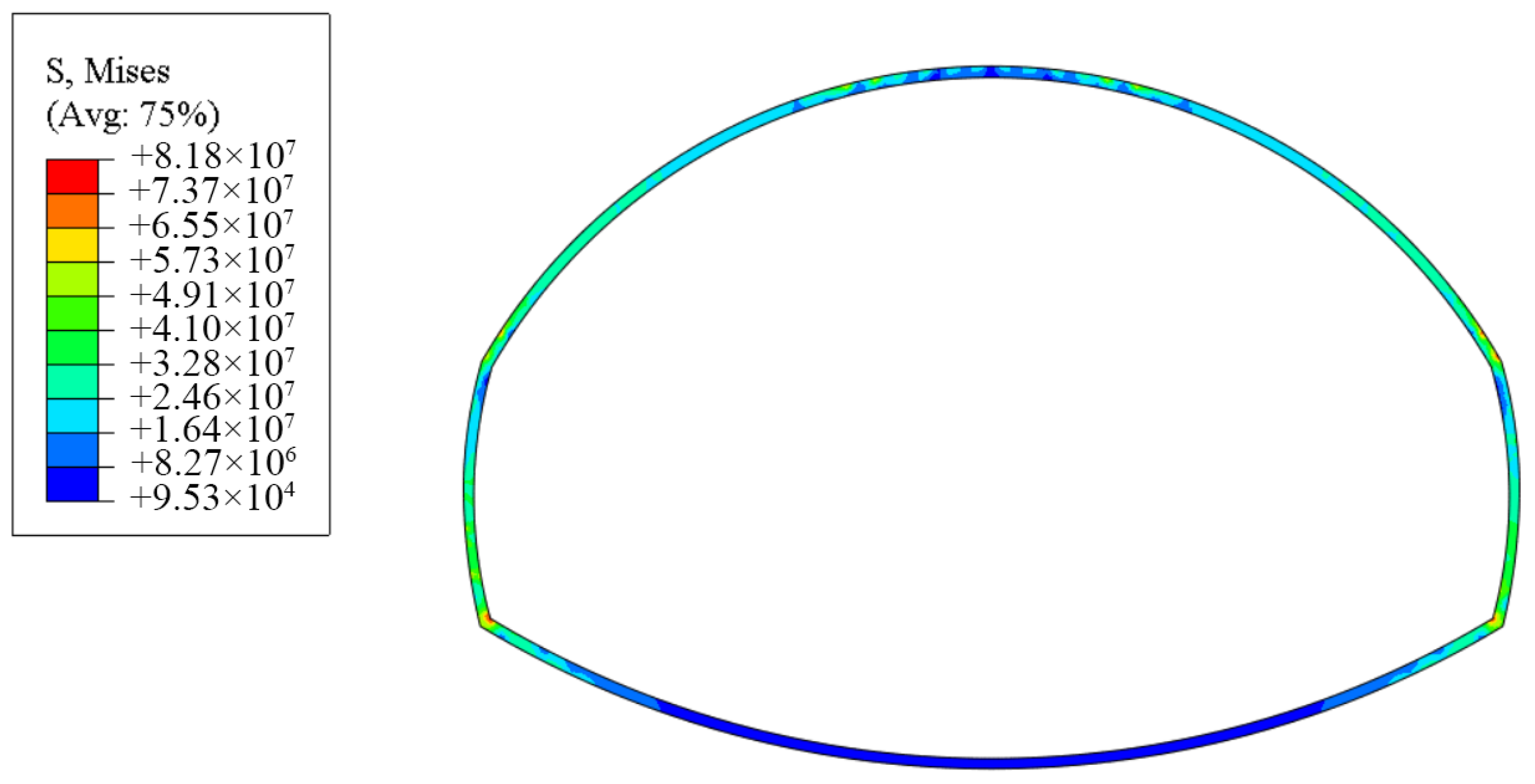
Taking a large-span tunnel with a span of 24.53 m in the southwest region, which is constructed through soft rock, as an example, this paper proposes a pilot-tunnel-leading construction method that can quickly construct soft rock tunnels. To ensure construction safety and quality, based on the original double-side wall pilot tunnel support design, 4 m long anchor rods are extended to 6 m. Additionally, 12 m long reinforced mortar anchor rods are applied at the node connection points of the steel arch frames, and the steel arch frames are also strengthened. A 13.2 m long pilot tunnel is excavated first. The Abaqus 2024 Version large deformation finite element analysis software was used to conduct a rationality analysis of the optimized construction plan, and a comparative analysis was performed between the double-side wall pilot tunnel method and the large-pilot-tunnel-leading method. The results show that the peak stress of the anchor rods occurs at the connection points of the steel arch frames in the large pilot tunnel, reaching 118 MPa. The maximum stress of the lining occurs at the right arch waist, reaching 91 MPa. For the double-side wall pilot tunnel method, the maximum arch crown settlement occurs at the arch crown position, reaching 12.5 mm. The peak stress of the anchor rods occurs at positions near both sides of the arch crown, reaching 120 MPa. The maximum stress of the lining occurs on both sides, reaching 81.8 MPa.
The results of numerical calculations show that, when the excavation method of the pilot-tunnel-first method is combined with the support measure of reinforced bolt lining, the construction quality is not significantly different from that of the original design scheme using the double-side drift method. This approach can ensure construction quality while accelerating the construction progress. For the 123 m tunnel advanced in the 24.53 m large-span section of the tunnel, the application of this optimized scheme increases the cost by approximately CNY 782,000, but shortens the construction period by 1.96 months, which greatly eases the pressure on the construction schedule. Meanwhile, this construction method has been applied in a soft rock large-span railway tunnel in southwest China, enabling the tunnel to open to traffic quickly along its entire length. The research in this paper can provide a reference for the design and construction of similar tunnels.

2. Engineering Overview

2.1. Geological Conditions of the Engineering

The tunnel area is characterized by a low mountain landform, with an elevation of 325 to 650 m and a relative height difference of 60 to 220 m. The tunnel roughly follows a northeast–southwest direction, crossing the mountainous area in a curved path. The vegetation is lush, mostly forested land, with exposed bedrock in some steep slope sections. The tunnel entrance is located near the gentle slope of a hillside, and the exit is situated near the middle slope of another hillside. The terrain at both the entrance and exit is relatively flat, and the alignment of both the entrance and exit is nearly perpendicular to the contour lines. The tunnel is located in a mountainous region where there are scattered roads, making transportation relatively convenient.
The exposed strata within the tunnel range include Quaternary Alluvial–Pluvial (Q4dl + pl) silty clay (soft soil) and slope-residual (Q4dl + el) silty clay; the bedrock consists of mudstone interbedded with sandstone and sandstone of the Upper Shaximiao Formation (J2s) of the Middle Jurassic Series. The tunnel is located near the core of the Dashengchang Syncline. The Dashengchang Syncline trends 20° east of north, with its northern end bulging westward in an arc shape, and has a length of 65 km. The axial part is composed of the Upper Shaximiao Formation, while the limb is composed of the Lower Jurassic Series. The syncline is broad, with an inclination of less than 7° near the axial part.
The rock mass in the tunnel area belongs to a weak water-rich rock group, with poor water-richness, basically no water, or a small amount of fracture water; atmospheric rainfall mostly flows into the ditch along the slope; the sandstone has a good permeability and water permeability, contains a small amount of fracture water, and its maximum water inflow is predicted to be 7326.8 m3/d; and the environmental action grade is H1. When salt crystallization destroys the environment, the environmental action grade is Y1, and the rest of the paragraphs are not erosive.
The large-span tunnel section is buried at a depth of 200–300 m, with geological conditions classified as Grade IV surrounding rock. The rock mass is primarily composed of mudstone and sandstone, with a rock mass uniaxial compressive strength of 6–7 MPa. The rock strata dip gently, and there is either no water or only a small amount of bedrock fracture water. The overall stability of the rock strata is good, and there are no adverse special geological conditions.

2.2. Tunnel Cross-Section Design

This large-span section of the tunnel is divided into two segments. The small mileage end of the large-span section is a signal machine lining with a maximum excavation span of 15.12 m, and the large mileage end is a Grade IV reinforced lining type with an excavation span of 12.78 m. The cross-sectional variation in each large-span segment is described as follows:
(1)
The section of the tunnel from DK43 + 150 to DK43 + 310 is a large-span segment with three-track divergence on the right side of the right connecting line of a large city railway station in southwest China. The entire large-span segment is 160 m long. At DK43 + 150, the left side remains unchanged while the right side makes a direct turn; the tunnel cross-section abruptly changes from 15.12 m × 13.61 m to 19.77 m × 14.33 m. At DK43 + 257, the tunnel cross-section again abruptly changes to 24.53 m × 16.2 m with a direct right turn. The plan layout of this large-span segment is shown in Figure 1.
(2)
The section from DK43 + 400 to DK43 + 577 is the three-line diverging large-span section of the station’s left connecting line. The total length of the large-span section is 184 m. At DK43 + 400, the right side remains unchanged while the left side makes a direct turn; the tunnel cross-section abruptly changes from 15.12 m × 13.61 m to 19.77 m × 14.33 m. At DK43 + 508, the tunnel cross-section abruptly changes to 24.53 m × 16.2 m with a direct left turn. The plan layout of this large-span section is shown in Figure 2. The comparative relationships of various cross-sections are shown in Figure 3.

3. Optimized Design of Excavation Cross-Section

3.1. Reasons for Section Optimization

This tunnel is the construction period-controlled project for the entire railway line, with extremely high pressure on the construction schedule. The large-span section is located on the critical path of the tunnel, and its construction progress directly determines the construction period of the entire line. Based on repeated construction period simulations of traditional construction methods (such as the double-side drift method and the CRD method) conducted by the scientific research and construction organization units, it was found that none of the existing construction methods could meet the construction period requirements of this project.
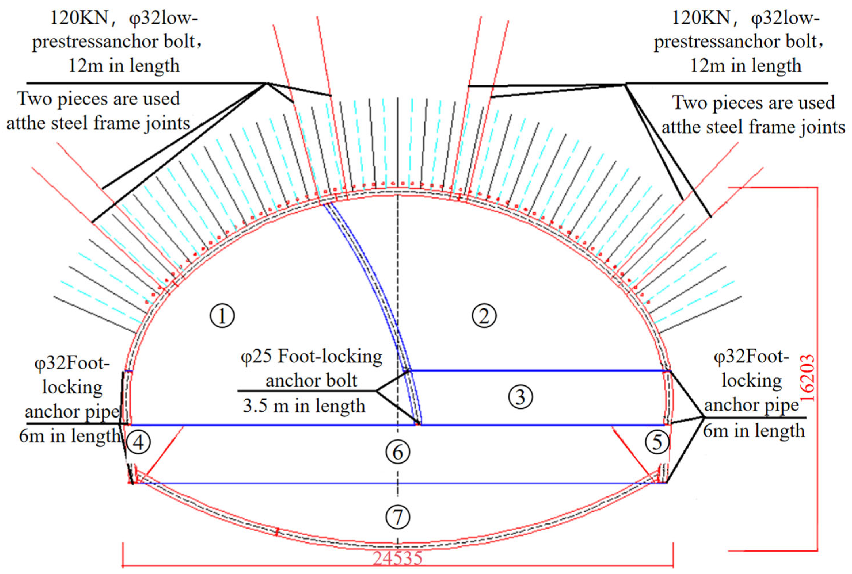
A study was conducted on the technical scheme for the large-span section of the tunnel, and an innovative idea of “large pilot tunnel first” was proposed. Specifically, the 24.53 m large-span section was constructed by first excavating a pilot tunnel with a width of 13.2 m (corresponding to the 13.2 m wide cross-section), followed by the expansion excavation of the remaining part, and long bolts were adopted for reinforced support. The construction schematic diagram is shown in Figure 4. The pilot-tunnel-first method can accelerate the construction progress to achieve optimization objectives. The length of the 24.53 m large-span section is 53 m. After the pilot tunnel excavation is completed, the cross-section transitions to the construction of a 15.12 m wide signal equipment section. To ensure that the construction processes do not interfere with each other, once the 15.12 m wide section provides a corresponding working face, the construction of the lower bench and inverted arch of the 15.12 m wide section will proceed first, skipping the 24.53 m large-span section. Whether the excavation of the 15.12 m wide section face can continue should be determined based on the analysis of surrounding rock monitoring data to assess its stability. If, during the construction process, the surrounding rock at the face is extremely poor, geological forecasts are abnormal, groundwater is relatively developed, or monitoring data show anomalies, excavation at the face must be stopped immediately. The safety step distance should be adjusted promptly, and targeted emergency measures should be taken.

3.2. Construction Plan

The cost comparison was based on the detailed bill of quantities and the official unit price list from the project’s construction contract. Excavation of Section ①: Shotcrete and an anchor were added to close the working face, and the initial support and temporary support were constructed around the pilot tunnel of this section. The temporary support connection nodes are connected by bolts (non-woven fabric is used to wrap the nodes before shotcrete construction for easy removal later). The next cycle of advanced support was constructed. The upper bench height of this section was 9.3 m, which could be appropriately adjusted according to the actual conditions to meet the requirements of mechanical operations.
According to the analysis of the monitoring measurement results, after the initial support converges, the expansion excavation work should be carried out. When excavating and removing spoil during the expansion excavation, it should be blasted, and spoil should be removed simultaneously with the working face of the leading pilot tunnel.
Excavation of Section ②: The advanced support for the next cycle was constructed. The height of the upper bench of this section was approximately 6.7 m, and the bench height could be adjusted appropriately according to the actual conditions to meet the requirements of mechanical operations. The excavation footage should not exceed two sets of steel frames. Initial Support Parameters: These included I25b steel ribs at a spacing of 0.5 m, with no more than two ribs installed per excavation cycle, and φ8 steel mesh with a grid spacing of 20 cm × 20 cm. The arch section was supported by φ25 self-drilling bolts, each 6 m long, arranged at 1 m × 1 m intervals (circumferential × longitudinal). At the steel rib connection nodes, two φ32 low-prestress bolts, each 12 m long, were installed.
The stair-step and invert arch construction was completed as follows:
After the completion of the support for Unit ③, since the pilot tunnel had already completed the upper bench construction of the signal machine section, the initial support closure of the invert arch for the 19.77 m large-span section had been constructed up to the section change at DK43 + 255.8. Due to the lack of vertical support during the construction of the transition section from DK43 + 255.8 to DK43 + 260.8, for construction safety, after the completion of the invert arch construction for the 19.77 m large-span section, the excavation was carried out on-site, alongside the initial support and lock-foot anchor pipes (rods) for the lower bench on the left side of Unit ④ for the 24.53 m section. The height of the lower bench is 3.7 m.
After lagging behind Section ④ by 3 m, the right lower bench of Section ⑤ was excavated and the initial support was constructed. After lagging behind Unit ⑤ by 3 m, weak blasting was carried out to excavate Units ⑥ and ⑦; the initial support of the inverted arch was promptly constructed to realize the full-section closed ring formation of the steel frame.
The initial support invert slab of the transition section was only 5 m, while the secondary lining invert slab was constructed in one cycle of 10.5 m. In order to ensure that, after the initial support invert slab of the 24.53 m wide section was closed into a ring as soon as possible, the secondary lining invert slab and backfill could be constructed promptly, the on-site actual construction situation, combined with the structural safety calculation data for the construction process changes provided by the design institute in the [Tunnel Large-Span Section Structural Safety Calculation Book], adopted the following approach: After constructing 3 m of the lower bench on the left side of Part ④, the lower bench on the right side of Part ⑤ was excavated, with core soil reserved in the middle. After the initial support deformation stabilized, temporary steel frame vertical supports were removed based on the monitoring measurement results of the expanded excavation cross-section.
After the temporary steel frame vertical supports were removed, the excavation of Units ⑥ and ⑦ was immediately carried out with controlled blasting. The initial support of the invert arch was promptly constructed to ensure the full-section closure of the steel frame into a ring. When the initial support invert arch steel frame closure of the 24.53 m large-span section in Units ⑥ and ⑦ reached 11 m, an on-site construction of the invert arch and its backfill was immediately organized. Based on the monitoring measurement data of the section during the 11 m invert arch excavation and support, the construction of the remaining sections was guided, thereby accelerating the full-section closure of the steel frame and the construction of the secondary lining invert arch and backfill while ensuring safety. After a section of invert arch construction, the secondary lining form traveler was assembled in the large-span section, and finally the arch and wall lining was poured in one go.

3.3. Cross-Section Monitoring Plan

When constructing in accordance with this advanced pilot tunnel plan, the excavation progress of the pilot tunnel is relatively fast, and there are many changes in the subsequent expansion excavation cross-sections. On-site, based on the surrounding rock conditions, advanced geological prediction results, and monitoring and measurement data, the maximum safe distance for the secondary lining is 155 m (comprising 90 m for the signal machine section, 53 m for the 24.53 m wide large-span section, and 10.5 m for the position of the lining trolley). For the inverted arch construction, according to the monitoring and measurement data of the large-span section, the inverted arch shall be excavated and the inverted arch lining constructed in a timely manner after the deformation of the expanded excavation section tends to be stable.
Monitoring Point Layout
(1)
Arch crown settlement and net space change
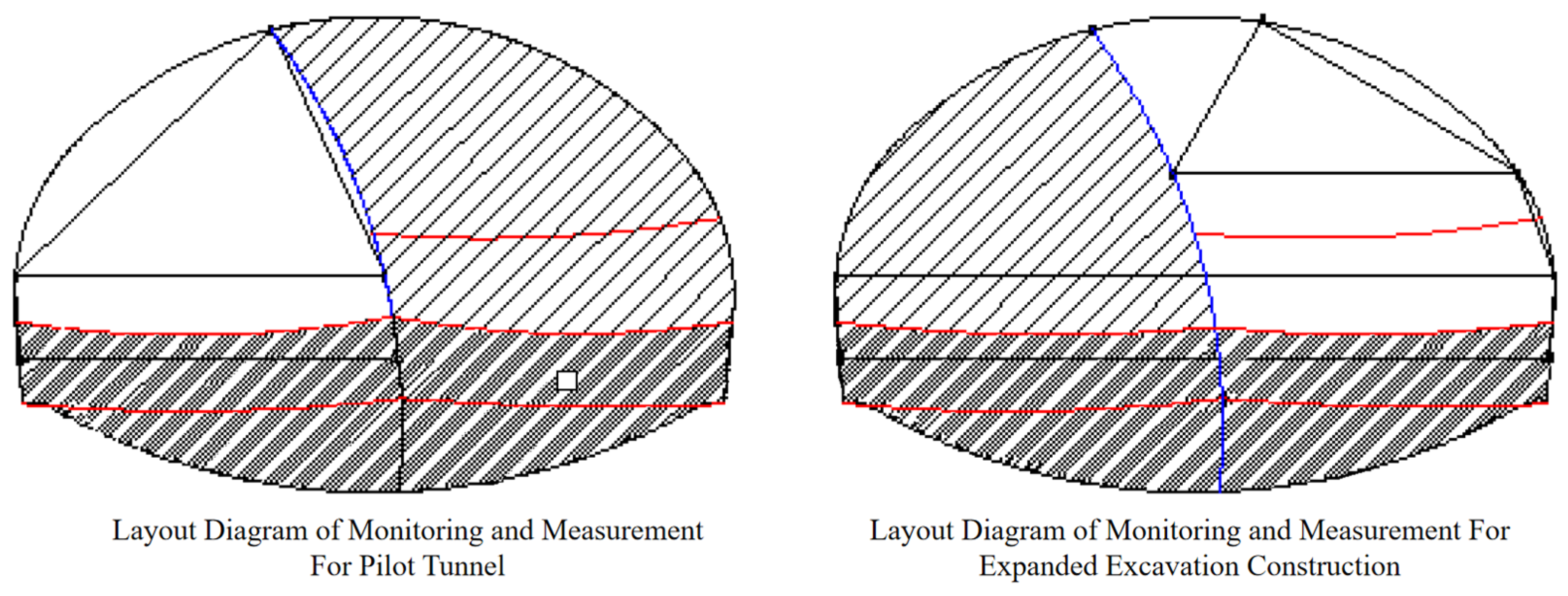
The arch crown settlement monitoring points and the net space change monitoring points should be arranged on the same cross-section. In principle, the arch crown settlement monitoring points should be set near the arch crown axis line. When the tunnel span is large, three monitoring points should be set at the arch crown position. The monitoring points of different cross-sections should be arranged at the same position, and the monitoring points should be arranged as symmetrically as possible to facilitate the mutual verification of data. The layout of monitoring points corresponding to different excavation methods is shown in Figure 5:
(2)
Special monitoring measurements
During the construction of auxiliary drifts 2# and 3# in the early stage of this tunnel, a bulging of the invert slab occurred. After geological investigation, it was determined to be horizontal mudstone invert bulging. Horizontal mudstone invert bulging is characterized by uncertainty and a lack of precursors. To monitor the cracking and bulging of the crown invert in the main tunnel, deformation observation points were set up on the top surface of the invert filling in the large-span section to monitor the upward bulging of the invert. The monitoring points were arranged at intervals of 20 m, with three points per section, located, respectively, on the top surface of the invert filling corresponding to the tunnel centerline, left line, and right line. The installation and observation frequency of the monitoring points were carried out in accordance with the relevant technical requirements of the “Technical specification for observation and assessment of settlement deformation of railway tunnels [33]” (Q/CR 9230-2016).

3.4. Optimized Costs and Schedule

Cost and schedule comparison of construction optimization plan
(1)
Cost Comparison
Based on the changes in the support parameters of the large-span section with a 24.53 m cross-section before and after optimization, the cost increase and decrease in the 24.53 m cross-section large-span section were calculated. By calculating the changes in engineering quantities caused by parameter changes, we found that the optimized version increases costs by approximately CNY 0.782 million. Among these, the main ones with a larger proportion are the following:
① The original vertical support steel frames of the double-side wall pilot tunnel method are upgraded from I18b to I25b steel frames, with the corresponding temporary support concrete thickness increased. The double-side wall horizontal and side wall temporary supports are canceled, and the initial support thickness is reduced. This results in a cost reduction of approximately CNY 1.778 million.
② The original design of the toe-lock anchor pipe used a seamless steel pipe with a diameter of φ42, with a single length of 4 m. After optimization, it was strengthened to φ76 steel pipe with a single length of 6 m. This item resulted in an additional cost of approximately CNY 1.014 million.
③ Additionally, 12 m extended anchor rods are added, and the cost for this item increases by approximately CNY 1.417 million.
④ The φ22 combined hollow anchor bolts in the arch are optimized to φ25 self-advancing anchor bolts, with the spacing changed from 1.0 × 0.5 m (ring × longitudinal) to 1.0 × 1.0 m (ring × longitudinal), keeping the anchor bolt length unchanged. The cost for this item is reduced by approximately CNY 0.907 million.
(2)
Schedule Comparison
The progress index for the 24.53 m large-span section in the optimized plan was originally 20 m/month. After scheme optimization, the leading pilot tunnel construction is expected to reach a progress index of 55 m/month. The expansion excavation can be carried out simultaneously with the face construction. Calculating only based on the excavation progress index, the pilot tunnel can be advanced in time by approximately (123/20 − 123/55)/2 = 1.96 months, which is beneficial, since the large-section pilot tunnel will be through ahead of schedule and will reduce the construction pressure in the later stage.

4. Feasibility Analysis of the Large-Pilot-Tunnel-First Method

4.1. Numerical Simulation Scheme

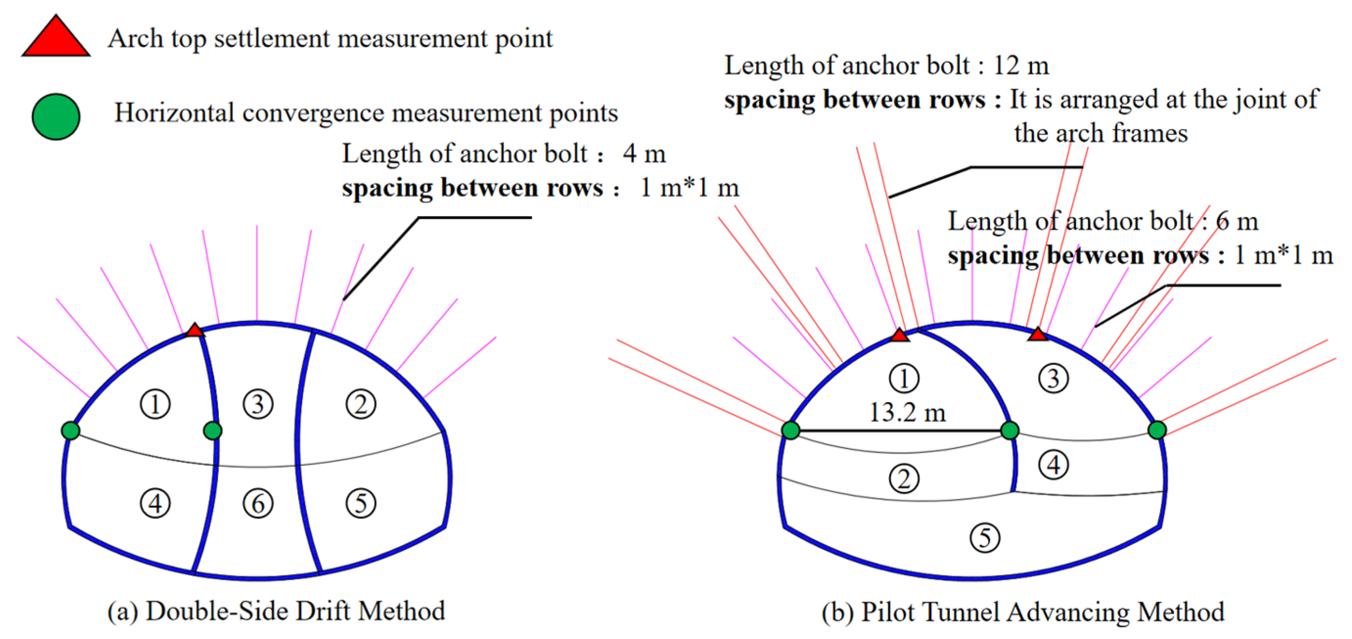
To verify the rationality and safety of the optimized design scheme, this study selected two construction schemes—the double-side drift method and the advanced pilot tunnel method—for comparative verification under a tunnel cross-section with a width of 24.53 m. The tunnel excavation steps and support design for different construction methods are shown in Figure 6. For the double-side drift method, full-length anchored bolts (4 m in length, with a spacing and row spacing of 1 m × 1 m) were used to simulate the working mechanism of mortar bolts. For the advanced pilot tunnel method, the 4 m long bolts were extended to 6 m, and 12 m long bolts were installed at the connection points of the steel arch frames to ensure the safety and stability of the surrounding rock at the steel arch connections. The reason for modifying the length of the anchor rod is to use the new construction method. We will strengthen the support to ensure that the safety factor is increased.
The deformation of the tunnel arch was monitored. For the double-side drift method, settlement observation points were set at the top of Excavation Section 1, Section 2 and Section 3, while horizontal convergence observation points were arranged at the arch haunches of Excavation Section 1 and Section 2. For the advanced pilot tunnel method, settlement observation points were placed at the top of Excavation Section 1 and Section 3, and horizontal convergence observation points were set at the arch haunches.
The numerical simulation was performed using Abaqus, a finite element analysis software suitable for describing the nonlinear large deformation behavior of rock masses. The dimensions of the model are shown in Figure 7, the rock mass has a height of 215 m and a width of 200 m, with a vertical distance of 155 m from the tunnel vault to the ground surface.
The surrounding rock was modeled using the Mohr–Coulomb elastoplastic constitutive model, which is widely adopted for simulating the failure behavior of soft rock masses. The bottom boundary of the model was fixed in all directions. The two lateral boundaries were constrained in the normal horizontal direction but free in the vertical direction. The top surface was set as a free surface to simulate the ground.
Before tunnel excavation, an acceleration of 9.8 m/s2 (acting vertically downward along the y-axis) was first applied to the rock mass to achieve geo-stress balance. Subsequently, calculations were conducted following the excavation steps illustrated in Figure 4. Prior to excavating each section of the rock mass, the corresponding bolts and linings at the edge of the rock mass were installed, followed by excavation. The bolts were coupled with the surrounding rock using the “Embedded” module to simulate the full-length anchorage of mortar bolts. A “Tie” contact was adopted between the lining and the surrounding rock to simulate the good construction condition of the lining.
The specific work content is divided into three steps: Step 1: in situ stress balance; Step 2: prefabricated installation of anchor bolt and lining; and Step 3: excavation. Then, the next cycle is performed.
The material parameters used for each component are presented in Table 1. The data come from the field test of the third-party laboratory commissioned during the implementation of the project. Among them, self-drilling mortar bolts were employed, with a yield strength of 335 MPa. These bolts are suitable for soft rock conditions and integrate drilling, grouting, and anchoring functions. In Abaqus, the “Truss” element was used for simplified calculation, and the corresponding cross-sectional area was set to 314 mm2. In the numerical simulation, the primary lining and secondary lining were treated as an integrated structure and applied to the surface of the surrounding rock together. The lining, consisting of steel bars and shotcrete, was calculated using the parameters of reinforced concrete, with an elastic modulus of 120 GPa and a yield strength of 200 MPa. Since the I18b steel arch frames were upgraded to I25b steel arch frames before and after the optimization of the construction scheme, the thickness of the optimized lining was increased by 10 cm. In the numerical simulation of this study, the lining thickness of the original double-side drift method was set to 20 cm, while that of the advanced pilot tunnel method was set to 30 cm.

4.2. Numerical Simulation Results

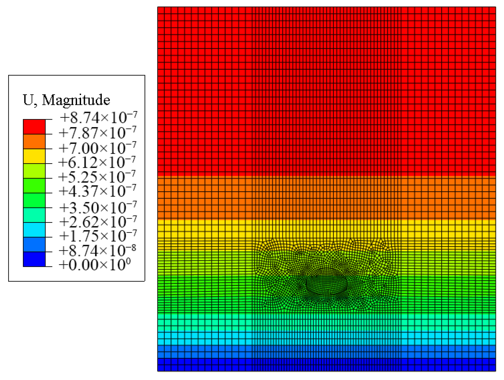
The distribution of the maximum and minimum principal stresses in the excavation model of this stratum is shown in Figure 8. In this model, the numerical height is 215 m, the gravitational acceleration is 9.8 m/s2, and the density is 2200 kg/m3. This converts to a vertical pressure at the bottom of 4.64 MPa, which is close to the minimum principal stress of 4.59 MPa. The minimum horizontal pressure is 2.16 MPa, resulting in a calculated lateral pressure coefficient of 0.47. This conforms to the conversion relationship for rock mass stresses in tunnel engineering. Therefore, the application of in situ stress in this model is valid. The displacement distribution after in situ stress balance is shown in Figure 9, with overall magnitudes between 10−7 and 10−8 m, which are negligible. This indicates that the stress balancing step has no effect on the initial displacement, confirming the effectiveness of the in situ stress balance.
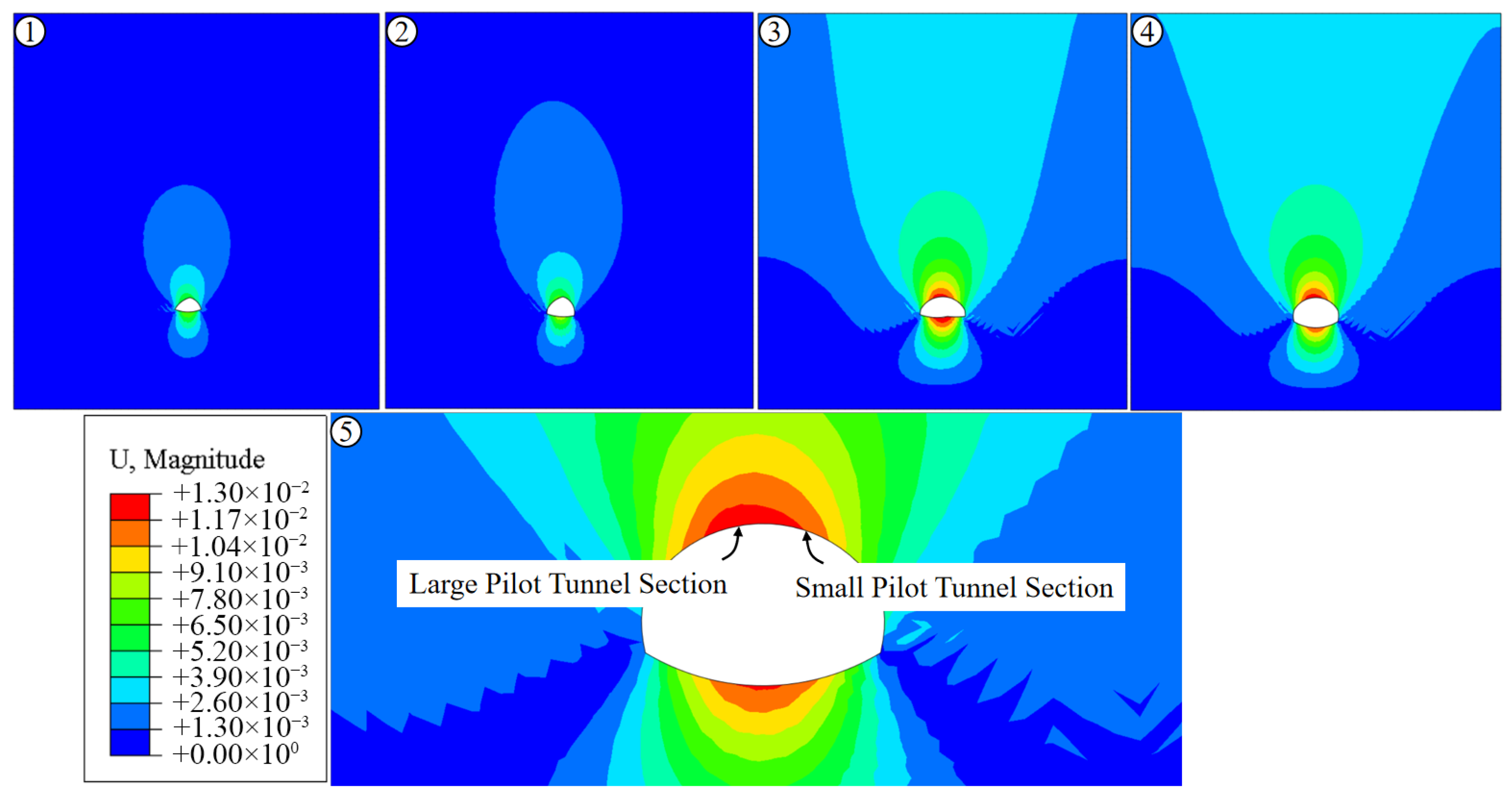
The displacement contour plot during construction using the pilot-tunnel-first method is shown in Figure 10. The maximum displacement occurs at the vault. As tunnel excavation proceeds, the maximum displacement continuously concentrates at the vault and the invert. The stress distribution of the tunnel upon stabilization after excavation using the pilot-tunnel-first method is shown in Figure 11, exhibiting a “butterfly”-shaped distribution. The maximum stress appears at the arch waist of the large pilot tunnel section, measuring 6.87 MPa. The stress on the sidewalls of the small pilot tunnel is slightly less than that in the large pilot tunnel, at 6.18 MPa.
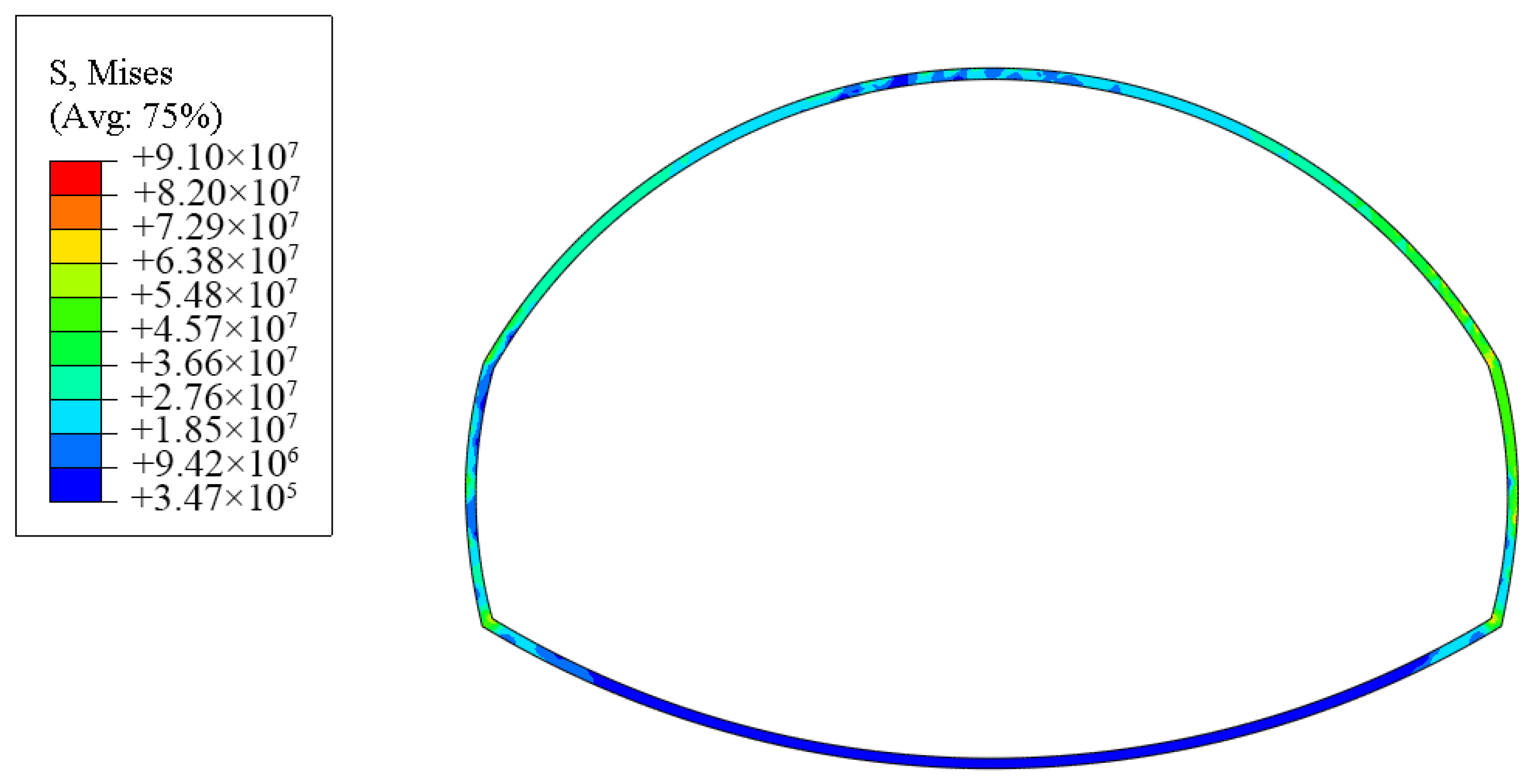
The rock bolt stresses are shown in Figure 12. The maximum stress of 118 MPa appears in the extended rock bolts at the vault and the left arch foot (spring line) of the large pilot tunnel. The overall stresses are within the elastic range, verifying the effectiveness of the rock bolt design. This also demonstrates that the design using extended rock bolts to ensure the stability of the surrounding rock at the steel arch connections is scientific and effective. The lining stress upon stabilization after tunnel excavation is shown in Figure 13. The maximum stress is 91 MPa, and the overall stresses are within the elastic range. The stresses at the crown and invert are relatively small. The maximum stress occurs on the right side of the steel arch, which corresponds to the area of higher stress at the arch waist in the small pilot tunnel section.
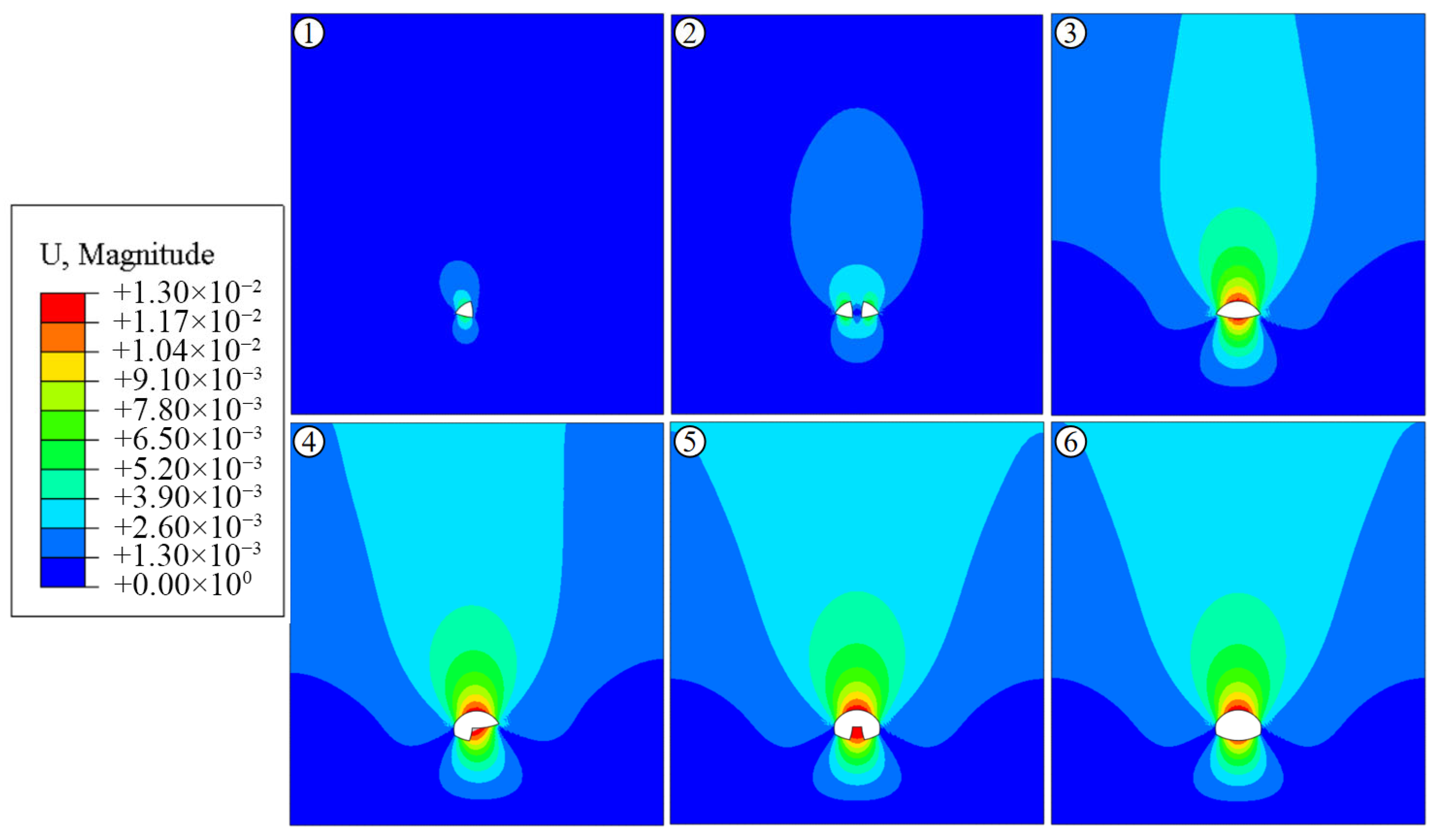
The displacement contour plot during construction using the double-side drift method is shown in Figure 14. Similarly to the pilot-tunnel-first method, the maximum displacement in the tunnel occurs at the vault and, as excavation proceeds, the maximum displacement continuously concentrates at the vault and invert.
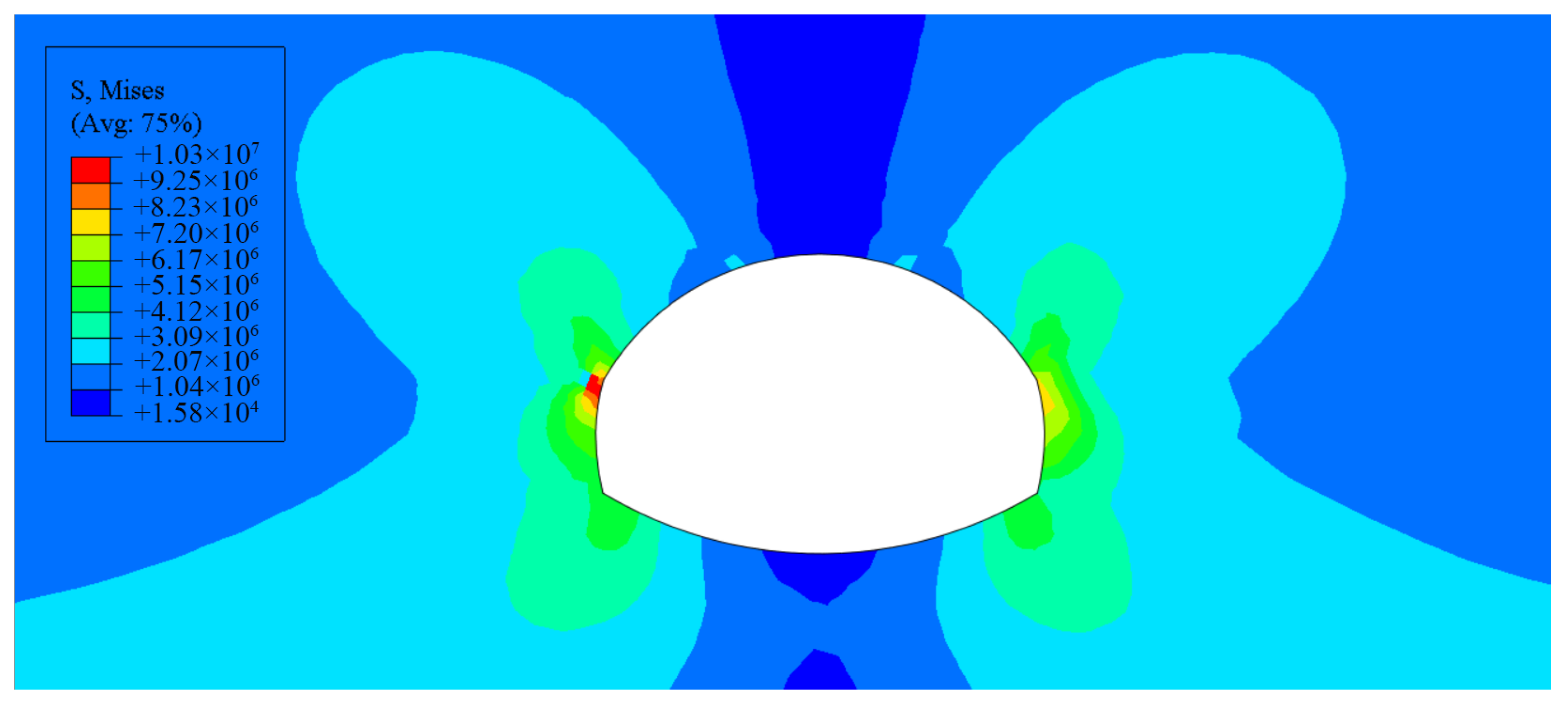
The surrounding rock stress upon stabilization after excavation using the double-side drift method is shown in Figure 15, overall exhibiting a “butterfly”-shaped distribution, with the maximum stress distributed at the arch waist sides. The rock bolt stresses are shown in Figure 16. The maximum stress of 120 MPa appears in the extended rock bolts at the vault and the left arch foot of the large pilot tunnel. The overall stresses are within the elastic range, confirming the effectiveness of the rock bolt design. The lining stress upon stabilization after tunnel excavation is shown in Figure 17. The maximum stress is 81.8 MPa, and the overall stresses are within the safe range. The stresses at the crown and invert are relatively small. The maximum stress occurs on both sides of the steel arch.
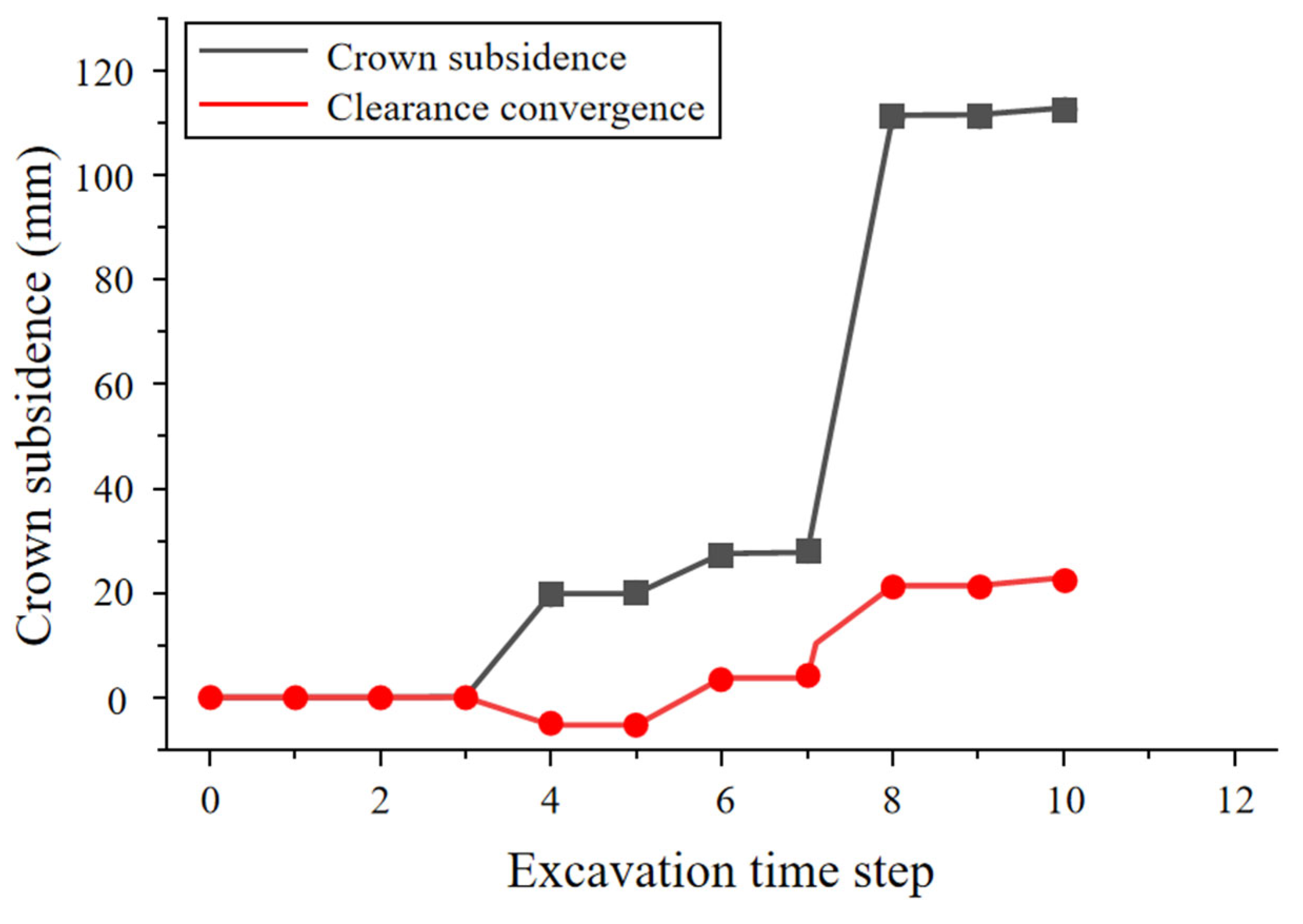
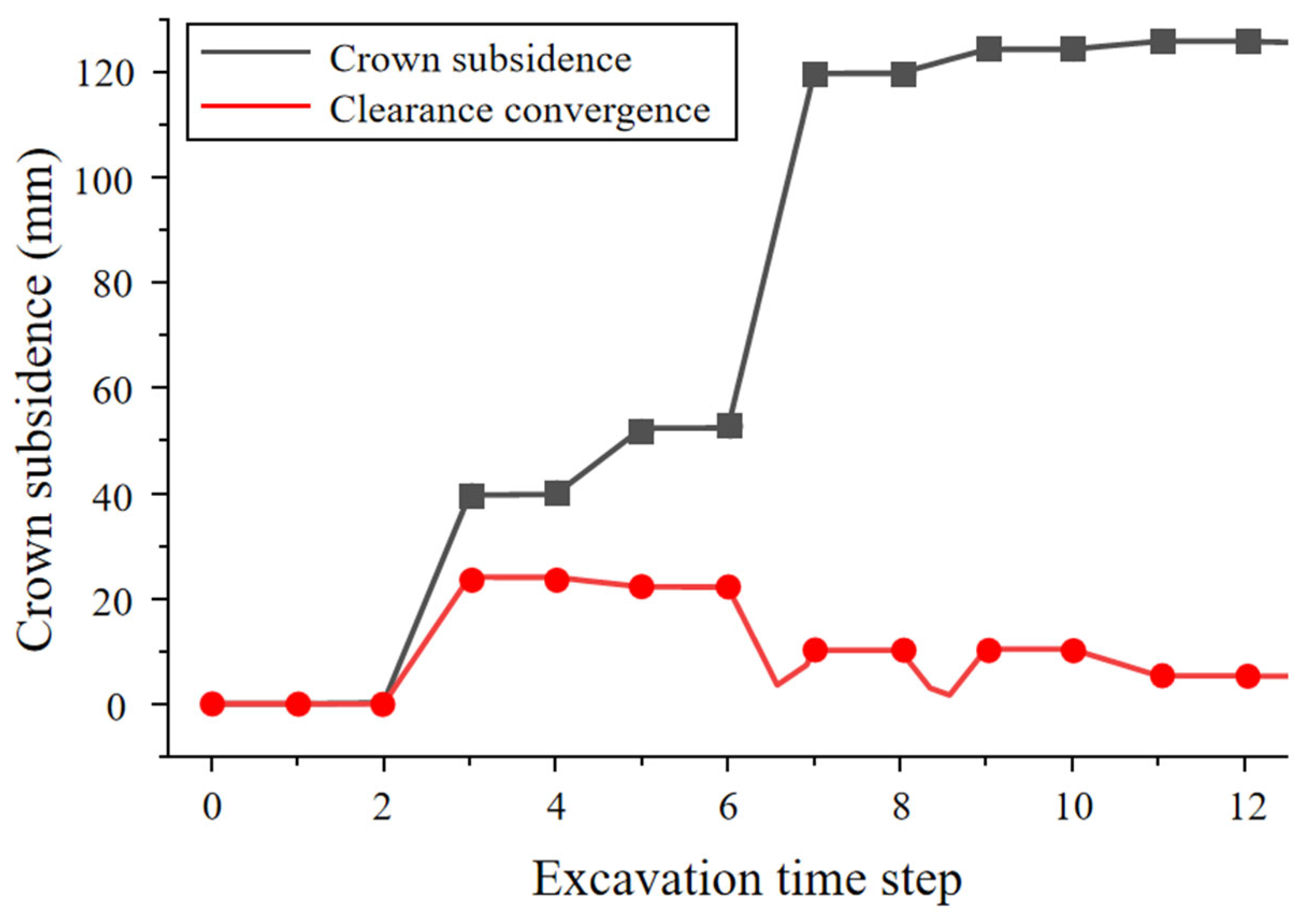
The numerical simulation results for the vault settlement and clearance convergence of the large pilot tunnel excavated using the advanced pilot tunneling method are shown in Figure 18. It can be observed that the maximum vault settlement reached 125 mm, while the maximum clearance convergence reached 95 mm. The relatively large cross-section and height of the pilot tunnel excavated in a single stage resulted in significant vault settlement and clearance convergence. The vault settlement and clearance convergence data for the small pilot tunnel are presented in Figure 19. The maximum vault settlement is similar to that of the large pilot tunnel, at 115 mm. However, the clearance convergence is smaller, approximately 20 mm.
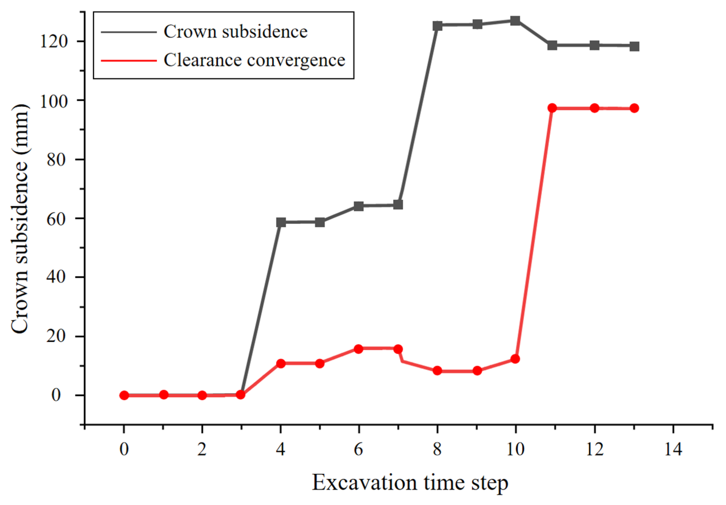
The displacement monitoring curve for the excavation using the double-side drift method in the numerical simulation is shown in Figure 20. The maximum vault settlement is 125 mm, which is similar to the results obtained with the advanced pilot tunneling method. Compared to the double-side drift method, the advanced pilot tunneling method employed 12 m elongated bolts, increasing the cost. This indicates that the optimized design is reasonable and ensures the stability of vault settlement. The maximum clearance convergence is approximately 20 mm.

5. On-Site Application Effects

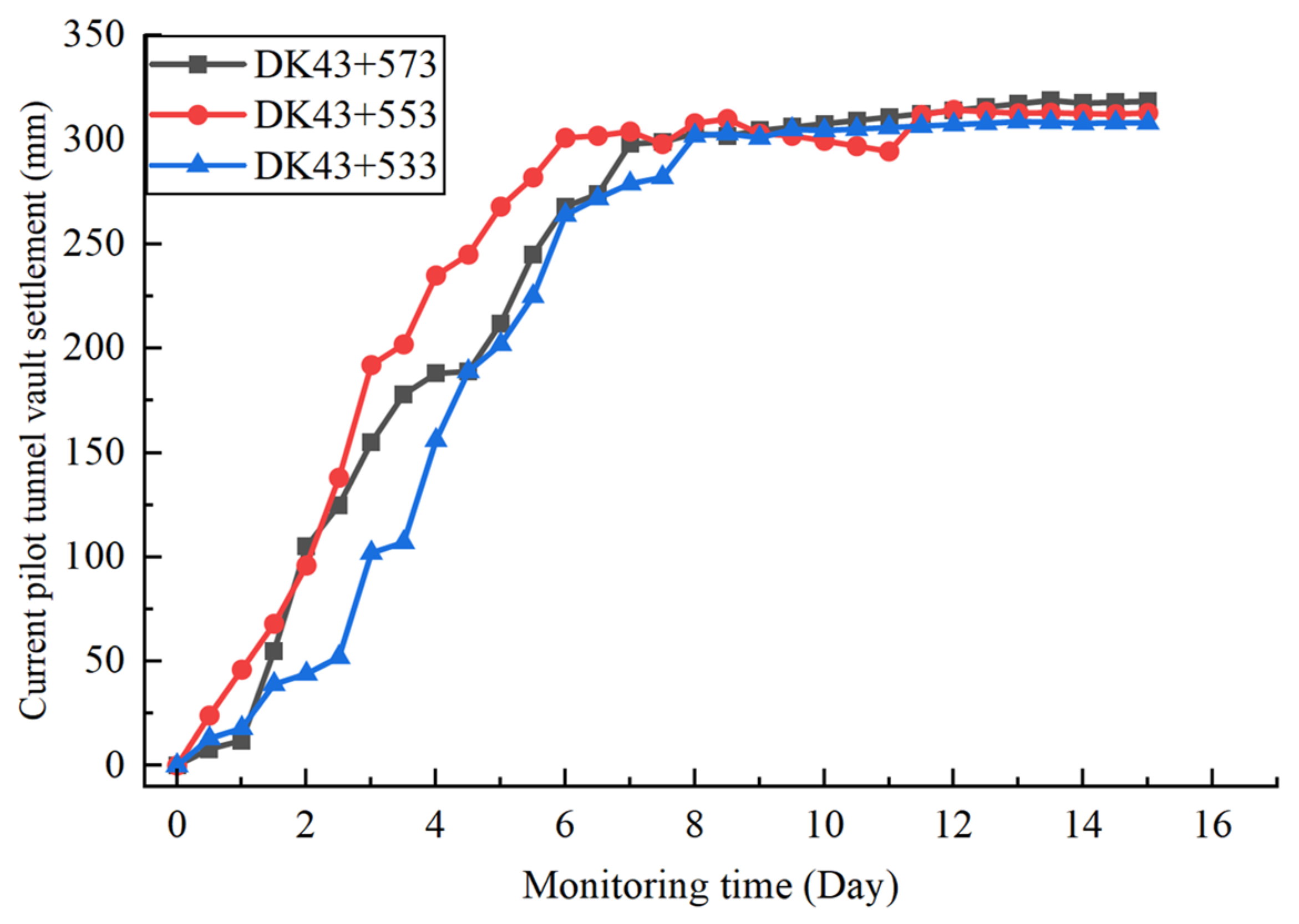
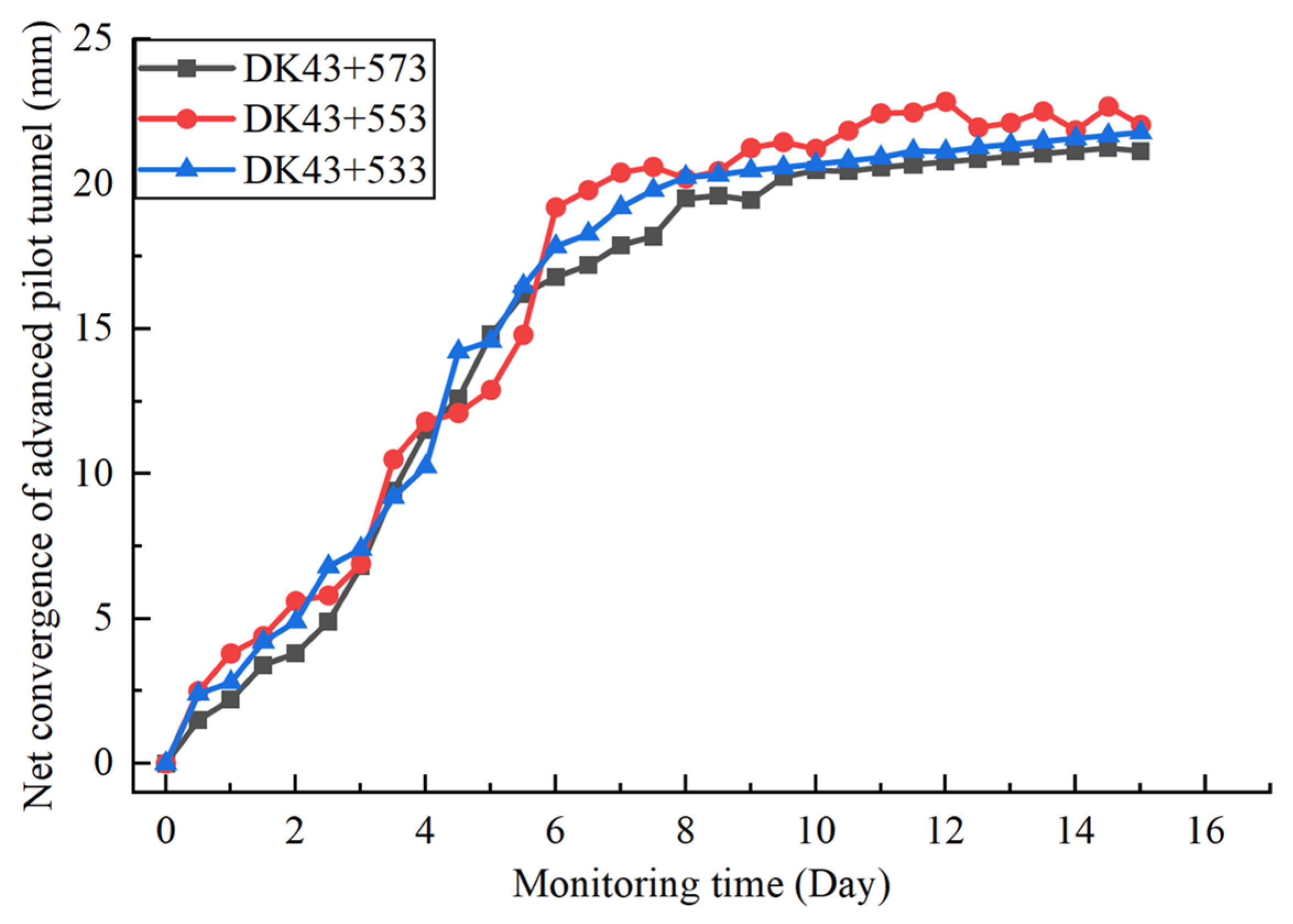
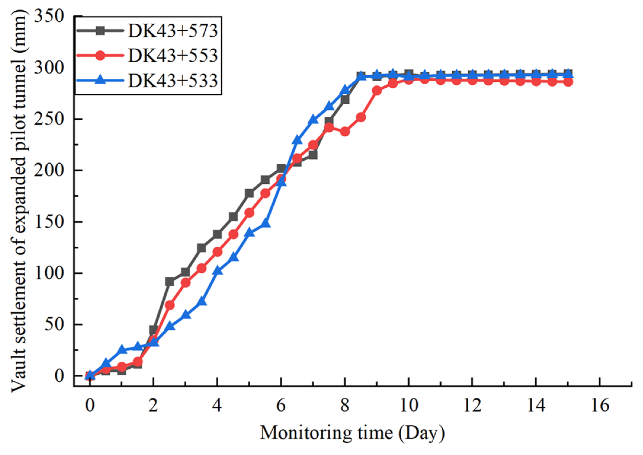
The on-site project was successfully implemented. The optimized scheme increased costs by approximately CNY 782,000 but reduced the construction period by 1.96 months. During the on-site construction process, monitoring was conducted on the displacement changes in vault settlement and clearance convergence of the large pilot tunnels and small pilot tunnels of the advanced pilot tunnel method arranged in Figure 5. On-site data monitoring was conducted using a high-precision total station, while numerical simulation data were extracted directly from the mesh data of the monitoring points. The monitoring started on the first day after tunnel excavation and lasted for 15 days. The tunnel mileage stakes for monitoring were DK43 + 573, DK43 + 553, and DK43 + 533, respectively.
Among them, the on-site measured data of vault settlement of the large pilot tunnels are shown in Figure 21. The vault settlement variation trends of the three mileage stakes are similar, indicating that the surrounding rock response is stable when the advanced pilot tunnel method is adopted for construction. Before the 8th day, the vault settlement of the large pilot tunnels showed an approximately linear upward trend; after that, it increased slightly with time, and the final settlement amount was about 305 mm. The on-site measured data of the clearance convergence of the large pilot tunnels are shown in Figure 22. Before the 8th day, the clearance convergence of the large pilot tunnels presented an approximately linear upward trend, and then increased slightly over time, with the final clearance convergence amount being around 22 mm.
The on-site measured data of vault settlement of the small pilot tunnels are shown in Figure 23. Similarly to the surrounding rock response trend of the large pilot tunnels, the vault settlement variation trends of the three mileage stakes are comparable. Before the 8th day, the vault settlement of the small pilot tunnels exhibited an approximately linear upward trend; afterwards, it increased slightly with time, and the final settlement amount was approximately 295 mm. The on-site measured data of clearance convergence of the small pilot tunnels are shown in Figure 24. Before the 8th day, the clearance convergence of the small pilot tunnels showed an approximately linear upward trend, and then increased slightly as time passed, with the final clearance convergence amount being about 13 mm.
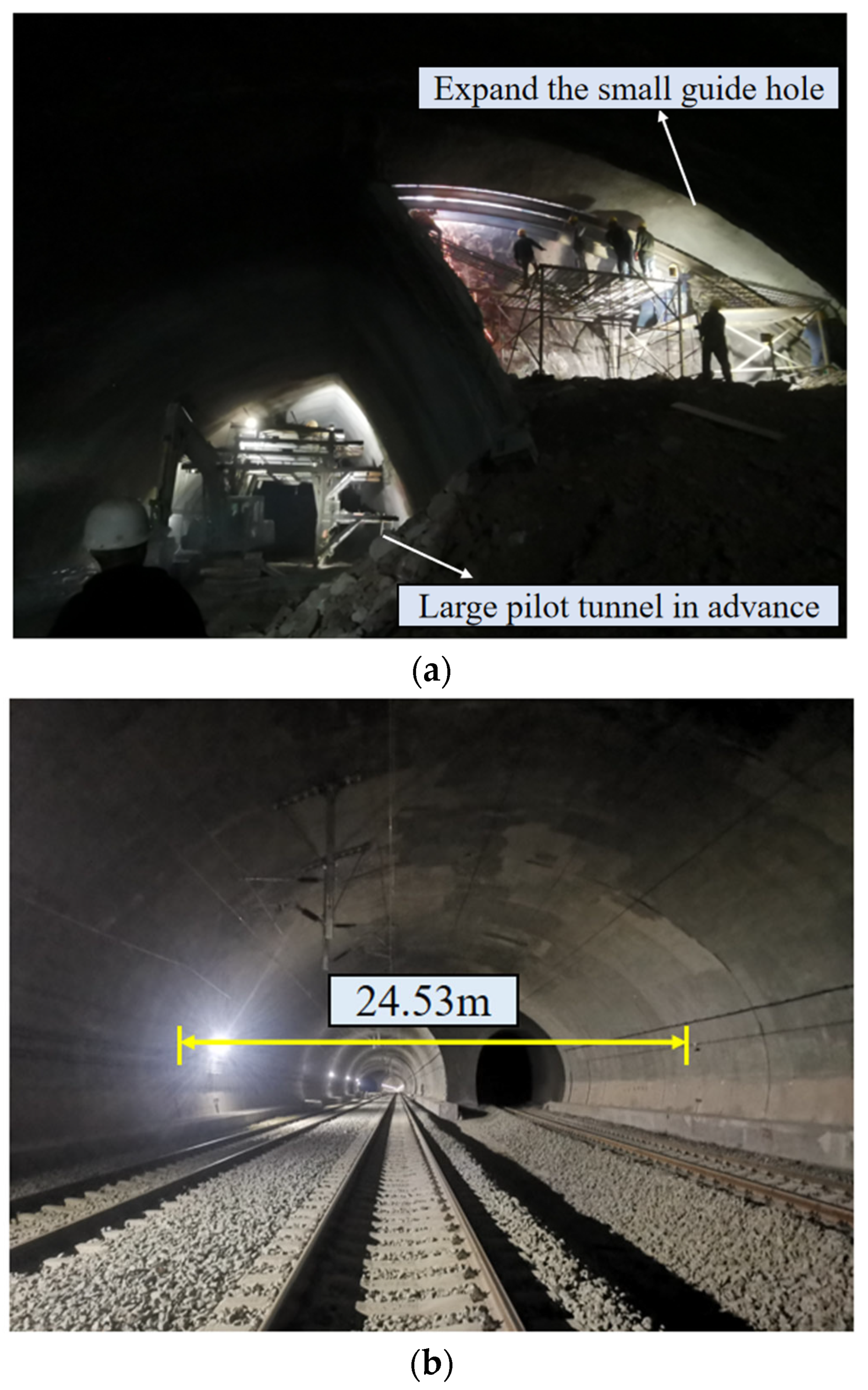
The construction processes of the large pilot tunnels and small pilot tunnels of the tunnel, as well as the tunnel after opening to traffic, are shown in Figure 25a,b. To realize the early opening of the tunnel to traffic, the construction progress of the advanced large pilot tunnels was faster than that of the expanded small pilot tunnels. After the tunnel was opened to traffic, the surface of the secondary lining of the tunnel with rails laid was smooth, and the deformation was controlled within 2 mm.

6. Discussions

The method proposed in this paper has been effectively applied in this case study, and this method is a new idea. Firstly, a small guide hole is used to open traffic, and then the expansion excavation is carried out, but its applicability is not absolute. In extreme environments, such as water-inrush tunnels or high-stress large-deformation tunnels, it may be more appropriate to adopt high-performance support systems and reduce excavation rates.
For the numerical simulations, the Mohr–Coulomb criterion was used to model the rock mass, and stable convergence solutions were obtained using Abaqus “Static, General” elements. However, we recognize that, in reality, rock masses transition to a plastic state through the development of fractures, whereas the plastic model in FEM simulations cannot replicate this effect, leading to underestimated numerical results. In the future, we will employ numerical methods such as FDEM that can simulate rock fragmentation to further investigate the excavation and deformation control of soft rock tunnels with large deformations.

7. Conclusions

(1)
To facilitate the rapid construction of a large-span tunnel in soft rock under high ground stress, the construction design for a 24.53 m span tunnel in southwestern China was optimized. The traditional double-side drift method was replaced by the pilot-tunnel-first method. Support measures were enhanced by increasing the bolt length from 4 m to 6 m, installing 12 m long reinforced mortar bolts at steel arch frame joints, and strengthening the steel arches themselves. This enabled the preliminary excavation of a 13.2 m large pilot tunnel.
(2)
The rationality of the optimized construction scheme was analyzed using the large-deformation finite element analysis software Abaqus, comparing the double-side drift method and the pilot-tunnel-first method. The results showed that the vault settlement and bolt axial forces in the large pilot tunnel section were greater than those in the small pilot tunnel section. The peak bolt stress (118 MPa) occurred at the steel arch joints in the large pilot tunnel, while the maximum lining stress (91 MPa) was located at the right arch waist. For the double-side drift method, the maximum vault settlement was 125 mm, the peak bolt stress (120 MPa) occurred near both sides of the vault, and the maximum lining stress (81.8 MPa) appeared on both sidewalls.
(3)
The numerical calculations and field application demonstrated that the pilot-tunnel-first method, combined with reinforced bolt-lining support measures, achieved a construction quality comparable to the original double-side drift design while significantly accelerating progress. Field monitoring indicated final stabilized vault settlements of 305 mm and 295 mm for the large and small pilot tunnels, respectively, with clearance convergences of 22 mm and 13 mm. For the 123 m advance in the 24.53 m large-span section, the optimized scheme increased costs by approximately CNY 782,000 but reduced the construction period by 1.96 months, substantially alleviating schedule pressure. This research provides theoretical reference and technical guidance for the design and construction of similar tunnel projects.

Author Contributions

Conceptualization, Q.F., H.Y., and J.Z. (Jiawang Zhan); methodology, Q.F. and J.Z. (Jianlin Zhou); formal analysis, X.X.; resources, J.Z. (Jiawang Zhan); writing—original draft preparation, J.Z. (Jiawang Zhan); writing—review and editing, H.Y. and H.G.; supervision, Y.S.; project administration, H.Y.; funding acquisition, H.G., H.Y., and J.Z. (Jiawang Zhan). All authors have read and agreed to the published version of the manuscript.

Funding

This work is supported by the National Natural Science Foundation of China (Grant No. 42502259), the China Postdoctoral Science Foundation—CCTEG Joint Support Program (Grant Nos. 2025T043ZGMK and 2025T049ZGMK).

Institutional Review Board Statement

Not applicable.

Informed Consent Statement

Not applicable.

Data Availability Statement

The original contributions presented in this study are included in the article. Further inquiries can be directed to the corresponding authors.

Conflicts of Interest

Author Hong Yang was employed by the company Municipal Engineering Co., Ltd. The remaining authors declare that the research was conducted in the absence of any commercial or financial relationships that could be construed as a potential conflict of interest.

Nomenclature

Q4dl + plQuaternary Holocene Alluvial–Pluvial Layer
Q4dl + elHolocene Alluvium of Quaternary System
J2sMiddle Jurassic Shaximiao Formation
Grade IV surrounding rockAccording to the “Highway Tunnel Design Specification” [33] to determine the level IV surrounding rock
DK43 + 150 to DK43 + 310The range of the mileage pile number is from 43 km 150 m to 43 km 310 m
φBolt diameter

References

  1. Hu, X.L.; Lin, S.L.; Lin, R.F. Influence from highways on regional economic growth based on the trade potential in China. Technol. Econ. Dev. Eco. 2025, 31, 184–210. [Google Scholar] [CrossRef]
  2. Moldovan, A. The impact of China’s road industry on the country’s economy. Mosc. Econ. J. 2024, 9, 35–46. [Google Scholar] [CrossRef]
  3. Lin, Y.M.; Huang, J.P. Can highway networks promote productivity? Evidence from China. J. Adv. Transport. 2021, 2021, 6860979. [Google Scholar] [CrossRef]
  4. Zou, Y.; Dong, X.J.; Feng, T.; Xu, Z.X.; He, H.L.; Wu, Z.L. Research on spatial prediction technology for mitigating tunnel inrush disasters under complex geological conditions in China’s Hengduan Mountain Range. Sci. Rep. 2025, 15, 1850. [Google Scholar] [CrossRef]
  5. Yang, X.J.; Kang, X.H.; He, M.C.; Wang, Y.J.; Zhang, J.; Shi, Z.; Chen, Y.W. Development characteristics and prediction methods of the “three zones” in overlying strata under the 110 mining method. Rock. Mech. Bull. 2026, 5, 100234. [Google Scholar] [CrossRef]
  6. Cui, T. Study on the Risk Forecast and Construction Technique of Karst Tunnel for Excavation and Support; Central South University: Changsha, China, 2011. [Google Scholar]
  7. Chen, Y.Y.; Xiao, P.W.; Li, P.; Zhou, X.; Liang, Z.Z.; Xu, N.W. Formation mechanism of rockburst in deep tunnel adjacent to faults: Implication from numerical simulation and microseismic monitoring. J. Cent. South Univ. 2022, 29, 4035–4050. [Google Scholar] [CrossRef]
  8. Hou, S.L.; He, M.C.; Yang, J.; Zhang, J.; Wang, Y.J.; Kang, X.H.; Han, Z.J.; Du, F.K. A green coal mining method for protecting roadways and overlying strata. Rock. Mech. Bull. 2025, 4, 100192. [Google Scholar] [CrossRef]
  9. Zhu, Z.Q.; Sheng, Q.; Zhang, Y.M.; Liu, S.W. Numerical modeling of stress disturbance characteristics during tunnel excavation. Adv. Mater. Sci. Eng. 2020, 2020, 4508905. [Google Scholar] [CrossRef]
  10. Liu, T.X.; Zhang, C.P.; Li, W.; Tu, S.Q.; Wang, L.B.; Jin, Z.X. Face failure mechanism of fault tunnels under high-temperature and high-pressure conditions using the discrete element method. Comput. Geotech. 2025, 179, 107059. [Google Scholar] [CrossRef]
  11. Zhang, L.X.; Chen, J.X.; Chen, L.J.; Luo, Y.B.; Liu, W.W. Deformation grading and prediction of heterogeneous layered soft rock tunnels under high ground-stress: A case study. Tunn. Undergr. Sp. Tech. 2026, 167, 107071. [Google Scholar] [CrossRef]
  12. Bai, C.H.; Xue, Y.G.; Qiu, D.H.; Yang, W.M.; Su, M.X.; Ma, X.M. Real-time updated risk assessment model for the large deformation of the soft rock tunnel. Int. J. Geomech. 2021, 21, 04020234. [Google Scholar] [CrossRef]
  13. Chen, L.H.; Xi, B.P.; Zhao, N.; He, S.X.; Dong, Y.S.; Liu, K.L.; Gao, P.L.; Liu, G.Q. Large deformation mechanism and support countermeasures of deep-buried soft rock tunnels under high geostress state. Buildings 2025, 15, 704. [Google Scholar] [CrossRef]
  14. Sun, J. Recent advances in rock rheological mechanics and its engineering applications. J. Rock. Mech. Geotech. Eng. 2007, 26, 1081–1106. [Google Scholar]
  15. Sun, J.; Jiang, Y.; Wang, B.; Fan, Y. Nonlinear rheological properties and yielding support technology for large squeezing deformation of soft rock tunnel with high ground stress. Tunn. Constr. 2021, 41, 1627. [Google Scholar]
  16. Li, S.C.; Wang, M.B. An elastic stress-displacement solution for a lined tunnel at great depth. Int. J. Rock. Mech. Min. 2008, 45, 486–494. [Google Scholar] [CrossRef]
  17. Li, Y.; Deng, F.; Zheng, J.; Wang, F.N.; Tao, Z.G. Study on the support strategy of NPR cable truss structure in large deformation soft rock tunnel across multistage faults. Rock. Mech. Rock. Eng. 2024, 57, 11261–11281. [Google Scholar] [CrossRef]
  18. Ren, L.X.; Wei, Z.F.; Liang, N.H.; Liu, X.R.; Deng, Z.Y. Mechanical behavior of multi-scale fiber-reinforced concrete for secondary tunnel lining: Field test and numerical simulation. Case Stud. Constr. Mat. 2022, 17, e01669. [Google Scholar] [CrossRef]
  19. Zhou, X.W.; Yang, S.; Ma, Z.G.; Ai, Z.B.; Tao, Z.G.; Sui, Q.R. A comparative study of soft rock tunnel control methods using NPR high preload anchor cables: Analysis of multiple cases. Ksce J. Civ. Eng. 2024, 28, 4703–4716. [Google Scholar] [CrossRef]
  20. Li, Y.K.; Wang, H.W.; Zhu, Z.B.; Deng, D.X.; Jiang, N.S. Integrative solution of stress evolution in overburden roof strata during the coal seam mining by application of complex variable functions methodology. Rock. Mech. Bull. 2026, 5, 100236. [Google Scholar] [CrossRef]
  21. Zhou, J.; Yang, X.N.; Ma, M.J. A new method for calculating the load shared by the primary support of deep-buried rheological soft rock tunnels by considering the flexible primary support. Int. J. Appl. Mech. 2024, 16, 2450034. [Google Scholar] [CrossRef]
  22. Li, C.J.; Zhuang, Y.Z.; Lu, Y.Q.; Zheng, G.P.; Zheng, Y.H.; Li, W.H.; Xue, C.B.; Guo, H.Y.; Fang, Y.C. Experimental study of the mechanical behavior of a steel arch structure used in the main lining of a highway tunnel. Buildings 2024, 14, 2571. [Google Scholar] [CrossRef]
  23. Li, Y.; Zheng, J.; Huo, S.S.; Wang, F.N.; He, M.C.; Tao, Z.G. Case study on the mechanics of NPR anchor cable compensation for large deformation tunnel in soft rock in the Transverse Mountain area, China. J. Cent. South Univ. 2024, 31, 2054–2069. [Google Scholar] [CrossRef]
  24. Sun, Y.P.; Xu, N.W.; Xiao, P.W.; Sun, Z.Q.; Li, H.L.; Liu, J.; Li, B. Characterizing large deformation of soft rock tunnel using microseismic monitoring and numerical simulation. J. Rock. Mech. Geotech. 2025, 17, 309–322. [Google Scholar] [CrossRef]
  25. Yang, W.B.; Zhao, L.L.; Yao, C.F.; He, C.; Pan, W.T.; Wu, F.Y.; Tian, L.Q.; Yan, Q.X. The control effect of directional rock bolt on asymmetric deformation of layered soft rock tunnel with different grades of large deformation. Rock. Mech. Rock. Eng. 2025, 58, 5273–5297. [Google Scholar] [CrossRef]
  26. Zhu, H.H.; Yan, J.X.; Liang, W.H. Challenges and development prospects of ultra-long and ultra-deep mountain tunnels. Engineering 2019, 5, 384–392. [Google Scholar] [CrossRef]
  27. Xu, Q.W.; Xie, J.L.; Zhou, F.; Tang, Z.H. Numerical Simulation and Analysis of the Causes and Distribution of Secondary Lining Cracks in Overlapping Railway Tunnels. Appl. Sci. 2023, 13, 6436. [Google Scholar] [CrossRef]
  28. Su, X.K. Study on the determination of boundary ranges for surrounding rock in tunnel excavation numerical simulations. J. Railw. Eng. Sci. 2012, 29, 64–68. [Google Scholar]
  29. Zheng, G.; Li, H.; Zhang, T.; Sun, J.; Wang, R.; Qiu, H.; Diao, Y. Exploratory Application of a Novel Centre Cross Diaphragm Method for the Construction of Large Cross-Section Tunnels in Soft Ground. Can. Geotech. J. 2023, 60, 123–138. [Google Scholar] [CrossRef]
  30. Ma, L.; Dai, J.; Wang, B.; Mo, Y.; Liu, Y.; Tian, C. Structural Analysis of Large-Span Tunnel Excavated by Upper Bench Center Diaphragm Method: An Analytical Model and Its Application. Tunn. Undergr. Space Technol. 2026, 167, 107053. [Google Scholar]
  31. He, M.; Gong, W.; Wang, J.; Qi, P.; Tao, Z.; Du, S.; Peng, Y. Development of a Novel Energy-Absorbing Bolt with Extraordinarily Large Elongation and Constant Resistance. Int. J. Rock. Mech. Min. Sci. 2014, 67, 29–42. [Google Scholar] [CrossRef]
  32. Zhan, J.; Yang, J.; Bian, W.; Zhao, R.; Dong, M. Analytical Study and Engineering Application of NPR Prestressed Bolt Is Anchored by Mechanical-Type Anchorage and Resin. Tunn. Undergr. Space Technol. 2024, 145, 105616. [Google Scholar] [CrossRef]
  33. Q/CR 9230-2016; Technical Specification for Observation and Assessment of Settlement Deformation of Railway Tunnels. China Railway Publishing House: Beijing, China, 2016.
Figure 1. DK43 + 150~DK43 + 310 large-span section layout plan [unit: m].
Applsci 15 12194 g001
Figure 2. DK43 + 400~DK43 + 577 large-span section layout plan [unit: m].
Applsci 15 12194 g002
Figure 3. The schematic diagram of the cross-section relationship of the large-span section of the tunnel [unit: m].
Applsci 15 12194 g003
Figure 4. The 24.53 m long-span section of the first pilot tunnel construction schematic diagram. [unit: mm].
Applsci 15 12194 g004
Figure 5. Survey line arrangement of vault subsidence measurement and clearance change measurement.
Applsci 15 12194 g005
Figure 6. Tunnel excavation steps and support design.
Applsci 15 12194 g006
Figure 7. Finite element model of tunnel geology and excavation section.
Applsci 15 12194 g007
Figure 8. Distribution of maximum principal stress and minimum principal stress.
Applsci 15 12194 g008
Figure 9. Displacement distribution after in situ stress balance.
Applsci 15 12194 g009
Figure 10. Displacement cloud diagram of pilot tunnel excavation process.
Applsci 15 12194 g010
Figure 11. Displacement cloud diagram of pilot tunnel excavation process with advanced method.
Applsci 15 12194 g011
Figure 12. Bolt stress distribution after excavation stability by pilot-heading advanced method.
Applsci 15 12194 g012
Figure 13. Lining stress after stable excavation of pilot tunnel by pre-excavation method.
Applsci 15 12194 g013
Figure 14. Displacement cloud diagram of double-side-heading excavation process.
Applsci 15 12194 g014
Figure 15. Stress distribution after excavation stability by double-side drift method.
Applsci 15 12194 g015
Figure 16. Stress distribution of anchor bolt after excavation stability by double-side drift method.
Applsci 15 12194 g016
Figure 17. Stress distribution of lining structure after stable excavation by double-side-heading method.
Applsci 15 12194 g017
Figure 18. Displacement monitoring curve of large pilot tunnel using pilot tunnel advanced method.
Applsci 15 12194 g018
Figure 19. Displacement monitoring curve of small pilot tunnel using pilot tunnel advanced method.
Applsci 15 12194 g019
Figure 20. Displacement monitoring curve of double-side-heading method.
Applsci 15 12194 g020
Figure 21. Field-measured curve of vault settlement of large pilot tunnel.
Applsci 15 12194 g021
Figure 22. The field-measured curve of the large pilot tunnel clearance convergence.
Applsci 15 12194 g022
Figure 23. Field-measured curve of vault settlement of small pilot tunnel.
Applsci 15 12194 g023
Figure 24. The field-measured curve of the small pilot tunnel clearance convergence.
Applsci 15 12194 g024
Figure 25. Field application effect of pilot tunnel advanced method. (a) Pilot tunnel excavation process; (b) tunnel after opening to traffic.
Applsci 15 12194 g025
Table 1. Material parameters used in the numerical simulation.
MaterialDensity [kg/m3]Elastic Modulus [GPa]Poisson’s RatioYield Strength
[MPa]
Cohesion
[KPa]
Angle of Internal Friction [°]
Bolt78502100.25335--
Lining25501200.25200--
Rock220050.32-8030
Disclaimer/Publisher’s Note: The statements, opinions and data contained in all publications are solely those of the individual author(s) and contributor(s) and not of MDPI and/or the editor(s). MDPI and/or the editor(s) disclaim responsibility for any injury to people or property resulting from any ideas, methods, instructions or products referred to in the content.