Abstract
Slide burnishing (SB) is a cheap and effective method for improving the surface integrity (SI) and operational behaviour (wear, fatigue, corrosion) of metal components. As its name suggests, SB is implemented through tangential sliding friction and is based on severe plastic deformation of the surface. The review presented here is dedicated to SB implemented using a non-diamond-based deforming element and aims to systematise the achievements from recent decades regarding SB’s effects on the SI, fatigue, wear and corrosion behaviour of metal components. Depending on the burnishing conditions (lubrication, cooling, assisting and their main effects on the treated surface), and based on the difference between the concepts of method and process, a classification of the types of SB processes was made based on the SB method—that is, conventional, sustainable, minimum quantity lubrication-assisted, special, hybrid and combined processes involving SB. Based on this classification, a critical analysis was conducted, viewed through the prism of correlations between the SB, SI and operating behaviour. With sustainability issues becoming increasingly relevant across all industries, more attention is being paid to sustainable SB processes. Because the finite-element method is a powerful and inexpensive tool that can be applied to the analysis of burnishing processes, we used it to build adequate finite-element models of SB processes. At the end of the paper, we outline avenues for future research on SB.
1. Introduction
As is known, the surface layers (SLs) of metal structural and machine components are the most stressed [1]. Surface layers are subjected to mechanical, thermal, chemical and physical influences (including physical fields), and most often to combinations of these. Some of these effects (e.g., corrosion) remain active even during periods when no operating load is being applied to the metal component. Depending on the influences applied, phenomena such as diffusion, corrosion, heterogeneous catalysis, adhesion and adsorption can occur in SLs, either autonomously or through mutual dependence. Localised damage due to the fatigue, wear and corrosion of SLs disrupts the normal interaction between components, causing scratching, jamming, impacts and vibrations. Therefore, the operational conditions, duration and reliability of technical devices depend, to the greatest extent, on the complex state of the SLs.
Therefore, SLs must be processed to perform functions that are different from those performed by the bulk of the material. The techniques and technologies for processing SLs fall within the scope of surface engineering (SE)—a scientific discipline established in England in the early 1970s—and have been aimed at (1) improving the corrosion resistance by establishing a barrier or other protection; (2) improving the resistance to oxidation and/or sulfidation; (3) increasing the wear resistance; (4) reducing the friction losses and improving lubrication; (5) improving the fatigue behaviour by increasing the fatigue limit; (6) increasing the microhardness (nanohardness); (7) improving the thermal insulation properties; and (8) improving the aesthetic appearance of the components.
There are several different types of processes used in SE [1,2,3], but the most appropriate is based on changing the chemical composition of the SL in one of the following ways (Figure 1): (1) modification based on the diffusion of new chemical elements into the SL (thermo-chemical diffusion), such as by cementation, nitridation or cyanidation; (2) modification by adding new material, in the form of a coating or thin film to create a barrier between the coated layer and the environment; and (3) modification without changing the chemical composition of the material. The latter direction is based on two main approaches—surface heat treatment and surface cold working—and a combination of these.

Figure 1.
SE processes.
The cheapest and most effective is surface cold working, which is aimed at plastically deforming the surface and adjacent subsurface layers of metal components at a temperature lower than that of recrystallisation. The methods used in this approach can be divided into dynamic and static. The idea of dynamic methods (impacting the treated surface with small particles) originates from the sand blast method, invented by Tilgham in 1871 [4]. Modern dynamic methods include, for example, shot peening [5], laser shock peening [6], cavitation peening [7], waterjet cavitation impact [8], surface mechanical attrition treatment [9] and percussive burnishing [10]. A common feature of dynamic methods is the dominance of the cold working effect (strain hardening) over the smoothing effect. In static methods (burnishing methods), a hard and smooth deforming element is pressed continuously and with constant force against the surface being processed, moving relative to it in a tangential direction. The tangential contact between the deforming element and the machined surface can be rolling friction or sliding friction. In the first case, the deforming element is a ball or roller (cylindrical, barrel-shaped or toroidal), the methods being ball burnishing or roller burnishing (RB), respectively. In the second case (sliding contact), the method is called slide burnishing (SB). The working surface of the deforming element in SB is most often spherical, less usually cylindrical or toroidal. The material of the deforming element is either a hard alloy, a natural diamond, or an artificial diamond. When SB is implemented using a diamond deforming element, the method is called diamond burnishing, as introduced by General Electric in 1961 [11]. Detailed information on the technological capabilities of diamond burnishing over the last six decades is contained in a review paper [12].
The subject of this review is SB, which is implemented using a non-diamond-based deforming element. The aim was to systematise the achievements regarding the effects of SB on the surface integrity (SI), fatigue, wear and corrosion of metal components, and to outline some avenues for future research.
2. The Essentials of SB
2.1. Mechanics of the Deformation Process
Slide burnishing is kinematically similar to machining, but instead of a cutting tool, an appropriately ended tool tip is moved, under normal pressure, over the treated surface of the metal workpiece [13]. In this way, the tool tip plastically deforms the surface and the closely located subsurface layers, producing two main effects—smoothing (a drastic reduction in the roughness height parameters) and strain hardening (a significant increase in the microhardness and the introduction of residual compressive stresses to a depth of about 0.8 mm). Improved SI results in enhanced performance of the slide-burnished component due to the increased wear and corrosion resistance, and fatigue strength [14].
An idealised scheme of the formation of the machined surface in the direction of the velocity vectors and feed rate by a spherical-ended deforming element is shown in Figure 2. This illustration includes the kinematics process, a constant depth of penetration () value for the deforming element and the homogeneous initial (pre-SB) micro-profile. Under the action of a normal (burnishing) force (), the deforming element penetrates the surface and subsurface layers to a depth . In the direction of the sliding velocity in front of the deforming element, a deformation wave with height () is formed (Figure 2a). Following the tool stroke, elastic recovery () of the material occurs. In the direction of the feed rate, the mechanism of formation of the machined surface is more complex. The formation of kinematic (theoretical) roughness is illustrated in Figure 2b. Because the elastic deformation is much smaller than the plastic deformation , it can be assumed that the radius () of the curve (depicted by a dotted line) is approximately equal to the radius (r) of the deforming element—that is, . Therefore, the theoretical micro-profile of the SL is formed based on the calculated peak-to-valley height using the following equation [15]:
where f is the magnitude of the feed rate.
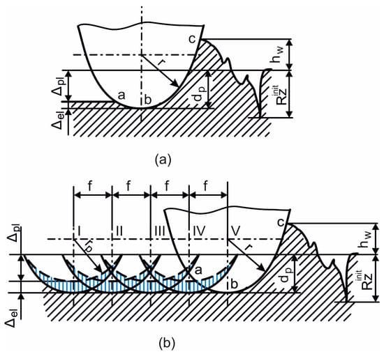
Figure 2.
Simplified scheme of the deformation process in SB: (a) in the direction of the SB velocity vector; (b) in the direction of the feed rate.
The theoretical average roughness () can be determined by the following equation [16]:
However, in addition to elastic recovery (), there can also be plastic leakage of the metal extruded from the deforming element in the direction of the slide burnished surface. In addition, the depth of penetration () will not be constant because of the uneven distribution of the initial micro-profile and the radial runout of the workpiece, among other random factors. The effect of the non-constant depth of penetration is more pronounced when using SB devices with an elastic contact between the deforming element, provided by an axial spring with constant stiffness, and the surface being processed. Therefore, the theoretical roughness values calculated by Equations (1) and (2) make sense rather in a qualitative way when comparing the effects of two SB processes implemented using different values of the governing factors.
2.2. Kinematic Schemes of SB Processes
Slide burnishing can be implemented on both universal and computer numerical control (CNC) machines (most often lathes) for finishing rotary (external and internal), planar and complex surfaces. The most common kinematic schemes for implementing various SB processes are shown in Figure 3.
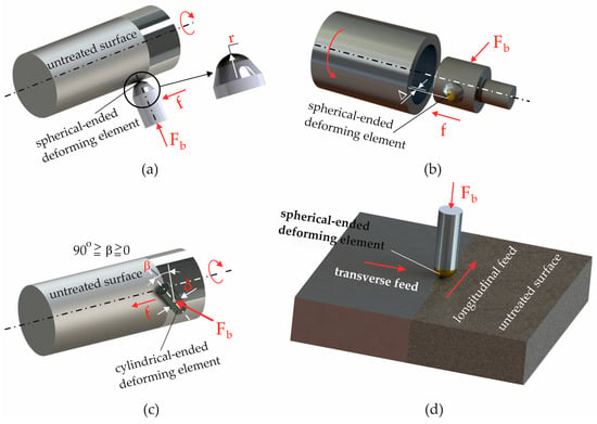
Figure 3.
The most commonly used kinematic schemes: (a) spherical-ended deforming element and external cylindrical surface; (b) spherical-ended deforming element and cylindrical hole; (c) cylindrical-ended deforming element and external cylindrical surface; (d) spherical-ended deforming element and flat surface.
2.3. SB Devices and Deforming Elements
Burnishing devices are used with either rigid or elastic contact between the deforming component and the treated surface. The first type is used for short-length surfaces, where the shape accuracy can be improved by one or two classes. The SB devices are characterised by their simplicity of design, low cost and ease of construction. The deforming elements are usually spherical, less often cylindrical. In some special SB methods [17], the working surface of the deforming element is toroidal. The material of the deforming element can be hardened tool steel, tungsten carbide (WC), or silicone nitride (), aluminium oxide () ceramic, silicon carbide (SiC) ceramic, WC-cobalt (Co)-cemented carbide or VC8 hard alloy, among others.
2.4. Governing Factors
The factors governing SB include the radius (r) of the working surface of the deforming element, the burnishing force () (or depth of penetration, when a burnishing device with a hard normal contact is used), feed rate (f), sliding (burnishing) velocity (v), and number of tool passes (n). These are the basic factors. Additional governing factors include the working scheme used when (one-way or two-way) and the burnishing conditions (presence or absence of lubrication and cooling).
2.5. SB Processes Depending on the Burnishing Conditions
Conventional SB is implemented under regular lubrication conditions using the same machine tool used for the previous machining (turning, drilling or milling using cutting fluid [CF]), aiming to provide the required initial SI. Therefore, problems related to the harmful effects of the CF during cutting on the environment and the machinist [18,19,20] are also valid in conventional SB. However, the CF in the SB process reduces the heat generated by the friction and plastic deformation, improves the SI, reduces tool wear and increases productivity due to treatment at higher speeds. Thus, the application of conventional SB is justified when applied to materials for which the use of CF is mandatory.
Solving the problems associated with the use of CF and its harmful impacts on the environment and human health is a prerequisite for achieving sustainable SB processes. Replacing CF with alternatives for lubrication and cooling in SB is a fundamental step towards realising sustainability [21]. Cryogenic-assisted (where the temperature in the zone of surface plastic deformation is below −180 °C), cool-assisted (where the negative temperature is higher than −180 °C), and dry SB processes can be introduced as sustainable processes [22], with dry SB being applicable where lubrication and cooling are not needed.
3. Conventional SB
Conventional SB processes have been investigated in several studies [23,24,25,26,27,28,29].
3.1. Effects on SI
The effects of conventional SB on the SI characteristics of treated metal components are summarised in Table 1. The following conclusions can be drawn: (1) too few studies have been dedicated to conventional SB; (2) the materials processed are various steels (structural, tool and stainless) with one exception—high-strength aluminium (Al) alloy; (3) all the studies focused on roughness, with fewer studies addressing microhardness and even fewer the residual stresses; (4) there is a lack of studies on the evolution of the microstructure due to SB; and (5) in general, the roughness height parameter values achieved are very similar to those obtained by the conventional diamond burnishing process [12].

Table 1.
SI characteristics obtained through conventional SB.
One interesting idea was described in Lin et al. [23], where the SB process was implemented based on the kinematic scheme shown in Figure 3c. These authors propose a generalised (integral) governing factor for the SB process (which the authors named the burnishing factor []). This is obtained based on a tribological model of the deforming element–machined surface system. The experimentally obtained relationship between the burnishing factor () and surface roughness is analogous to the Stribeck curve [30], which describes the relationship between the Hersey number (a dimensionless lubrication parameter [31]) and the coefficient of friction. If it is assumed that there is a strict dependence between the coefficient of friction in the paired deforming element–processed surface (and a dependence undoubtedly exists) and the resulting roughness, then the physical meaning of the burnishing factor () proposed by the authors is precisely the Hersey number.
Figure 3a illustrates the SB, as implemented by Elsamanty et al. [27], while the kinematic scheme in Figure 3d has been used in various other studies [24,25,28,29]. Dyl et al. [26] applied SB to cylindrical holes using a kinematic scheme in which the relative motion between the tool (with a spherical or cylindrical working surface) and the workpiece was a rectilinear translation parallel to the hole axis (Figure 4). This process was coined ‘SB broaching’ by the authors.
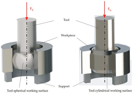
Figure 4.
SB broaching kinematic scheme.
3.2. Effects on Operating Behaviour
Only one study was devoted to the effects of conventional SB on the operating behaviour of processed components. Dzierwa et al. [25] investigated the tribological behaviour of a paired steel disc–counterbody (ball). The discs (42CrMo4 hardened steel) were subjected to SB with different ceramic materials used as the deforming element. The counter body was made of 100Cr6 steel with a hardness of 62 HRC. The authors found that the lowest values of the volumetric wear parameter were recorded when SB was implemented using an deforming element with a 70 N burnishing force, or using a SiC-deforming element and a 30 N burnishing force. In addition, the authors established several dependencies between the parameters characterising the topography of the disc surface and the wear volume (i.e., SI–operating behaviour correlations). A strong linear relationship was established for the parameters characterising the bearing area curve (the Sk, Svk and Spk three-dimensional [3D] roughness parameters), as well as for the 3D shape roughness parameters (Ssk and Sku) of the surfaces. Wear tests proved the beneficial effects of SB (for all types of deforming element materials used in the study) on the reduction in volumetric wear in the friction pairs compared to other popular methods, such as grinding, lapping and polishing.
4. Sustainable SB Processes
To be a sustainable process, SB must be carried out under dry, dry + cool, or cryogenic burnishing conditions. Our review showed that there is a lack of research on cool-assisted SB under dry conditions. Sustainable SB processes have been investigated in several studies [32,33,34,35,36,37,38,39,40,41,42,43,44,45,46,47,48,49,50,51,52,53,54].
4.1. Dry SB
The effects of dry SB on SI characteristics are summarised in Table 2. The conclusions that can be drawn are very similar to those made for conventional SB: (1) very few studies have been devoted to sustainable dry SB; (2) the materials processed were structural steels, high-strength Al alloy and magnesium (Mg) alloy; (3) the studies were focused on roughness and microhardness, with no studies on residual stresses; (4) in contrast to conventional SB, two studies [34,37] were devoted to the evolution of the microstructure due to dry SB; and (5) in general, the values achieved for the roughness height parameters were similar to those obtained from the conventional diamond burnishing [12].

Table 2.
SI characteristics obtained after dry SB.
Buldum and Cagan [32] studied the influence of the governing factors on the roughness parameter (Ra) and surface microhardness of AZ91D magnesium alloy. Slide burnishing was implemented according to Figure 3a. Based on the signal-to-noise ratio, these authors found that the feed rate had the strongest influence on Ra, followed by the burnishing force, with the weakest influence being the burnishing velocity. However, the influence of the governing factors on the microhardness was quite different, with the burnishing force having the strongest influence, followed by the burnishing velocity, while the number of passes had the weakest influence. The same governing factors were used by Esme [33], who applied the grey Taguchi method to optimise dry SB of 7075 AA (see Figure 3a). The burnishing force had the strongest influence on the average roughness and surface microhardness, followed by the number of passes, with the burnishing velocity having the weakest influence.
Kato et al. [34] applied dry SB in the surface nanocrystallisation of normalised medium-carbon steel using a spherical-ended WC-Co cemented carbide deforming element (Figure 5). The authors obtained a nanocrystalline structure of the surface and near-surface subsurface layers, with grain sizes ranging from 10 to 300 nm, the grain sizes increasing approximately linearly with depth from the surface. Ultrafine and equiaxed grains 10 nm in size were found, generated by the recrystallisation caused by the friction-induced plastic deformation.
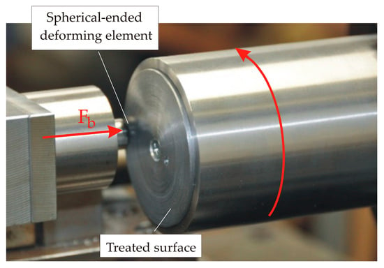
Figure 5.
Kinematic scheme of the SB of flat rotating surfaces.
Kato et al. [35] applied SB using a spherical-ended ceramic deforming element (Figure 5) to finish the front (plane) surface of a disc-type specimen (the track diameter of the burnished area was 38 to 52 mm), and investigated the influence of the initial roughness (after turning and before SB) on the ability of this type of finishing to improve the average roughness and surface microhardness. These authors found that the smoothing effect of SB was limited, and that the maximum roughness height for burnishing smoothing increased under a higher burnishing force and with a larger radius of the deforming element.
Bobrovskij et al. [36] investigated the physical nature of the dry SB (implemented by a cylindrical-ended W-Co deforming element) of low-alloy 43 and 38 steels (Figure 3c; ). In the study, the influence of two values (0.8 and 1.25 μm) of the initial average roughness, burnishing force (100–200 N) and friction in the contact zone on the stability and energy efficiency of the SB process was investigated. The authors proposed a new criterion for the effectiveness of SB, based on the temperature in the contact zone of the deforming element and the treated surface, for which they derived a regression model using the variables of the initial roughness and burnishing force. The new criterion simplifies the selection of governing factors and prevents unwanted structural transformations in the SL, which would worsen the SI and the operational reliability of the treated surface. In addition, the wear of the deforming element was reduced, which is essential for dry SB.
Kuznetsov et al. [37] developed a scheme and a new tool for dry SB, using a flat cylindrical deforming element made of cubic boron nitride (c-BN) for nanostructuring the SL of hardened AISI 52100 steel. The kinematic scheme of the SB process is shown in Figure 6. Changing the angle of inclination of the deforming element relative to the surface being processed allows the contact pressure and plastic deformation to be controlled, which results in nanostructuring through severe plastic deformation.
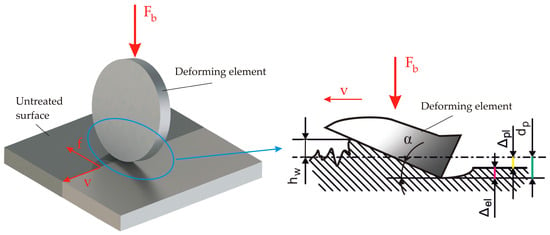
Figure 6.
Kinematic scheme of the SB process, implemented in [37].
A new SB method—friction stir burnishing—applied to SS400 carbon steel has been described and studied [38,39,40]. This method involves a rotating tool with a deforming element with a flat working surface (Figure 7). Under dry burnishing conditions, the thermal softening effect dominates over the strain hardening effect due to the accumulation of friction heat, which leads to annealing of the SL of the material. As a result, the maximum microhardness is at the surface, in contrast to the effect caused by cool-assisted friction stir burnishing, where the maximum microhardness occurs below the SL.
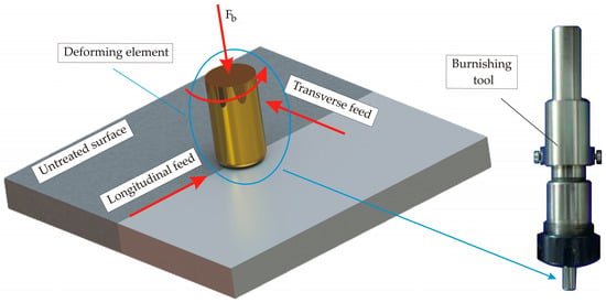
Figure 7.
Kinematic scheme of the SB process, implemented in [38,39,40].
Research on the effects of dry SB on the operating behaviour (fatigue, wear, corrosion resistance) of treated surfaces is lacking.
4.2. Cryogenic-Assisted SB
The effects of cryogenic-assisted SB on SI characteristics are summarised in Table 3. The following conclusions can be drawn: (1) significantly more research has been devoted to cryogenic-assisted SB than to conventional and dry SB processes; (2) reports on its application to steels are lacking; and (3) its effects on SI characteristics have been studied significantly more comprehensively than for conventional and dry SB processes.

Table 3.
SI characteristics obtained after cryogenic-assisted SB.
Pu et al. [41,42,43,44] applied cryogenic-assisted SB to improve the SI and operating behaviour of AZ31B-O Mg alloy. The kinematics of the process is illustrated in Figure 8. The specimen is in the form of a disc, with mounting holes for attachment to a machine spindle that rotates around its axis. The deforming element is a fixed roller, made of high-speed tool steel, which is pressed against the cylindrical surface of the disc to be machined. The average roughness achieved was 0.225 μm [41,42,44]. The authors found that room-temperature grinding provided lower roughness compared to cryogenic SB. However, the surface microhardness resulting from cryogenic SB reached 1.35 GPa, while the microhardness of the base material was 0.9 GPa [41,42,44]. Cryogenic SB introduces positive surface hoop residual stresses, while the axial stresses introduced are compressive, but with smaller absolute values than with dry SB [43,44]. The explanation for the positive hoop stresses is the relatively large tangential force of 500 N, which the deforming stationary roller exerts on the processed cylindrical surface of the disc. As is known, in RB, this force is negligibly small. The authors found that cryogenic SB homogenises and greatly refines the grains in the surface and nearby subsurface layers [41,42,43,44]. The reason is that the cryogenic temperature (below –180 °C) suppresses grain growth in dynamic recrystallisation. Therefore, the mechanism for grain refinement is dynamic recrystallisation. In addition, the authors found that the refined microstructure significantly improved the corrosion resistance of the treated surface.
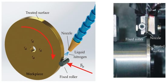
Figure 8.
Kinematic scheme of the SB process, realised in [41,42,43,44].
Singh et al. [45] used cryogenic-assisted SB to improve the properties of WC-10Co-4Cr thermal spray coating on a flat specimen using a carbide-based disc-type tool rotating around a fixed axis, with the specimen performing a rectilinear translation (feed motion) (Figure 9). The authors reported a significant reduction in the average roughness (Ra = 1.94 µm to 0.84 µm), a more than 30% increase in surface microhardness, an isotropic region of compressive surface stresses, larger than in dry SB, and a reduced porosity of the SL.
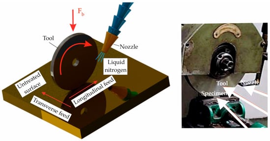
Figure 9.
Kinematic scheme of the SB process, implemented in [45].
Tang et al. [46,47] implemented cryogenic-assisted SB to improve the SI and corrosion resistance of Ti-6Al-4V cylindrical parts using a cylindrical cemented carbide deforming element in which the axis was orthogonally crossed with the axis of the rotating cylindrical workpiece (see Figure 3c at ). The authors reported a significant reduction in initial roughness (up to Ra = 0.35 μm) after cryogenic-assisted SB, while dry SB significantly worsened the roughness. The combination of low roughness with a nanostructured SL led to a significant increase in corrosion resistance. The authors explained this effect as the formation of a more rapid, stable and less defective passive film on the surface nanocrystalline layer due to its high density of grain boundaries and dislocations.
Yang et al. [48,49,50,51,52,53,54] improved the SI of AZ31B-O [48] and Co-chromium (Cr)-molybdenum (Mo) [48,49,50,51,52,53,54] alloys, as well as their operational behaviours (corrosion and wear resistances), via cryogenic-assisted SB using the kinematic scheme shown in Figure 8 [48,49,50,51,52,54]. Figure 10 shows the cinematic scheme used by Yang et al. [53]. The authors reported an average roughness of 0.58 μm (smaller than the roughness achieved by dry SB) and a significantly higher surface microhardness (95% improvement over the microhardness of the base material) of AZ31B-O Mg alloy compared to the effect achieved by dry SB. In addition, remarkably refined microstructures were formed on the burnished surface, with grains less than 300 nm in diameter being observed. As a result, a significant increase in the corrosion resistance of AZ31B-O alloy was achieved. Similar results were achieved for a Co-Cr-Mo alloy. The authors reported a 40% reduction in the average roughness (compared to the initial average roughness) and an 80% increase in the surface microhardness (compared to that of the base material). The microhardness obtained by cryogenic-assisted SB to a depth of up to about 230 μm was greater than that obtained by dry SB. Compared to dry conditions, the cryogenic SB provided two times smaller grains beneath the processed surface, and the severe plastic deformation layer thickness was increased by up to 170%. Using an infrared camera, the authors established that in the contact zone of the deforming element–processed surface, the temperature was above 700 °C during dry SB, while during cryogenic-assisted SB, the temperature was below 300 °C. This reduced temperature hinders the growth of grains during dynamic recrystallisation, which is the reason for the highly refined structure.
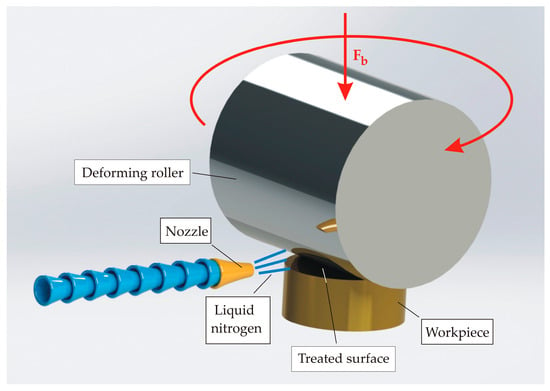
Figure 10.
Kinematic scheme of the SB process, realised in [53].
Residual stresses have been studied in detail by Yang et al. [52]. Cryogenic SB, with its depth of penetration of 0.127 mm, introduces larger axial stresses, both on the surface and at depth, than dry SB. As a result, the compression zone is deeper. When the depth of penetration is increased to 0.254 mm, the cryogenic SB introduces larger compression stresses (compared to dry burnishing) at a depth of about 50 µm, after which the trend reverses. As a result, the compression zone introduced by cryogenic SB is smaller than that obtained by dry SB, and the distribution of residual hoop stresses is the complete opposite. The effect of cryogenic-assisted SB on the wear resistance of a Co-Cr-Mo alloy has been established [52] using a pin-on-disc tester. Cryogenic SB provides minimum wear volume losses compared to dry SB. The authors explained this phenomenon in terms of microstructure refinement, compressive residual stresses and the preferred hexagonal close-packed phase of the SL. Moreover, the preferred hexagonal close-packed phase was found to be the most influential property in enhancing the wear resistance.
5. Minimum Quantity Lubrication-Assisted SB
5.1. Effects on SI
The minimum quantity lubrication (MQL) strategy (as its name suggests) was developed to drastically minimise the amount of CF consumed in machining processes. Minimum quantity lubrication is associated with the use of between 10 and 50 mL of CF per machine h [18]. However, for a process to be sustainable, it must fulfil three key demands—economic, environmental and social. The use of MQL partially reduces pollution and lubrication costs, but does not improve working conditions (the social aspect), due to the oil mist formed during its application, which cannot be completely eradicated and is the cause of numerous diseases [20]. Therefore, the MQL-assisted SB process cannot be classed as a sustainable SB process because it occupies an intermediate (hybrid) position between conventional and sustainable processes.
The effects of MQL-assisted SB on SI characteristics are summarised in Table 4. The following conclusions can be drawn: (1) few studies have been devoted to MQL-assisted SB; (2) related studies have focused on roughness and microhardness, whereas residual stresses have not been investigated; and (3) studies on the evolution of the microstructure due to MQL-assisted SB are lacking.

Table 4.
SI characteristics obtained after MQL-assisted and cool + MQL-assisted SB.
Bobrovskij et al. [36] compared the effects of two SB processes—dry and MQL-assisted—implemented using a cylindrical-ended deforming element for finishing cylindrical low-alloy medium-carbon steel specimens using the kinematic scheme shown in Figure 3c (where ). The authors found that (1) while the burnishing force is equally important in both processes, the initial roughness only affected the dry SB; (2) MQL not only improves the stability of the SB process but also increases its energy efficiency by more than 20%; and (3) the temperature of the deforming element–machined surface contact zone in MQL-assisted SB is more than 70 °C lower than the temperature of the same zone in dry SB.
A comparison of the effects on the average roughness and microhardness of three friction stir SB processes under different burnishing conditions (dry, MQL-assisted and cool + MQL-assisted) has been made [38,39,40]. Figure 7 shows the kinematics of the process (friction stir burnishing), and Figure 11 illustrates the average roughness results for different diameters of the deforming element [39,40]. With the increasing diameter of the deforming element, the average roughness decreases. The authors noted that the trend of the results is similar to the trend of the average thrust force. The higher the value of the average thrust force, the higher the value of the average roughness. The cool + MQL-assisted SB provides the lowest Ra value, while the dry SB resulted in maximum Ra values. The cool + MQL burnishing condition provided solid lubrication and an effective cooling rate, thus reducing the thrust force and friction at the tangential tool–workpiece contact.

Figure 11.
Surface microhardness due to different burnishing conditions and tool diameters.
Figure 12 shows a comparison of the cross-sectional microhardness profiles obtained from the friction stir SB under different burnishing conditions for a tool with a diameter of 16 mm [38]. The cool + MQL condition significantly increased the microhardness (by 7.4 and 46%, respectively) compared to the MQL-assisted and dry conditions. Under dry conditions, the effects of thermal softening dominate over the effects of strain hardening, the reason being the heat generated in the stir SB friction zone, which leads to an annealing process. This results in a softer surface than with the other two cooling techniques. The cool + MQL and MQL-assisted conditions increased the microhardness by accelerating heat removal, such that greater strain hardening occurs under the burnished surface. In addition, the removal of more heat due to the cool-assisted process allows the microstructure of the material to be compressed at a higher thrust force. Thus, the effect of strain hardening dominates over the thermal softening effect. As a result of the opposition of these two effects, the maximum microhardness value occurs under the surface under cool conditions, while under dry conditions, the maximum microhardness value occurs at the surface.
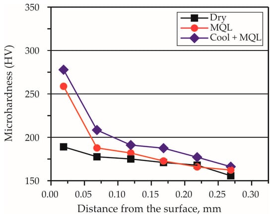
Figure 12.
Comparison of cross-sectional microhardness profiles obtained by friction stir SB under different conditions.
Sagan et al. [55] applied MQL-assisted SB to cylindrical WE43 Mg alloy specimens using a hardened 52100 steel ball as the deforming element. The kinematic scheme for the SB process was implemented according to Figure 3a. The authors achieved a lower average roughness and a higher surface microhardness than with dry SB.
5.2. Effects on the Operating Behaviour
Research on the effects of MQL-assisted SB on the operating behaviour (fatigue, wear, corrosion resistance) of the treated surfaces is lacking.
6. Special SB Processes
The special SB methods reviewed here were categorised based on the following criteria: (1) their complex kinematics; (2) employing special tools with additional functions; and (3) their purpose (e.g., for processing large, small or complex surfaces, a large number of surfaces, etc.). These SB processes have been investigated in several studies [56,57,58,59,60,61,62,63,64,65,66].
6.1. Effects on SI
The effects of special SB processes on the SI characteristics of treated metal components are summarised in Table 5. The following conclusions can be drawn: (1) a relatively large number of studies have been devoted to special SB, which indicates a desire to expand the traditional areas of application of conventional SB; (2) the processed materials are steels (structural and stainless) and non-ferrous alloys; (3) all the studies have focused on roughness, while the microhardness and residual stresses having been of less interest; and (4) studies on the evolution of microstructure due to special SB are lacking.

Table 5.
SI characteristics obtained through special SB methods.
Processing large flat surfaces using conventional techniques is a time-consuming process. To solve this problem, Gharbi et al. [56] developed a special tool that increases the productivity of conventional SB. The process kinematics is shown in Figure 13. In addition, the authors found that the treated 1050A Al SB moderately reduced the roughness height parameters and improved ductility, but the microhardness measurements showed little or no hardening of the specimen surface, which can be explained by the specific structure of the material.
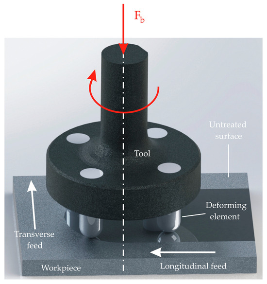
Figure 13.
Kinematic scheme of the special burnishing tool developed in [56].
Maximov et al. [57,58,59] developed a spherical motion burnishing (SMB) method, intended for both finishing holes and external cylindrical surfaces. The kinematic schemes for SMB are shown in Figure 14. The axes of the tool (deforming element) and the machined surface intersect at a small angle (θ), with the intersection point coinciding with the pole of symmetry of the working surface (spherical for holes and toroidal for external cylindrical surfaces) of the deforming element. With respect to the stationary workpiece, the deforming tool performs a superposition of spherical motion (adding rotations around intersecting axes—rotation around the axis of the machined surface with an angular velocity and a simultaneous rotation around its own axis with an angular velocity , where the absolute angular velocity () is the vector sum ) and rectilinear translation along the axis of the machined surface. Spherical motion allows for a significant reduction in the axial force (), a reduction in the roughness height parameters and an increase in the microhardness compared to the conventional case, where the relative motion between the tool and the workpiece is only rectilinear [26]. The SMB process, implemented with relatively simple devices (Figure 15), thus expands the technological capabilities of conventional machine tools.
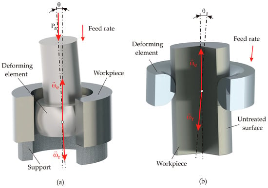
Figure 14.
Kinematic schemes of the SMB method: (a) SMB of holes; (b) SMB of external cylindrical surfaces.

Figure 15.
SMB implementation: (a) device and tools for SMB of holes; (b) SMB of holes on milling machine; (c) and (d) SMB of external cylindrical surfaces on conventional and CNC lathes, respectively.
Okada et al. [60] developed a new SB method that employed a rotary diamond-like-carbon-coated carbide deforming element (Figure 16) to improve the SI of a nickel (Ni)-based alloy. The specific kinematics of the method allow a significant improvement in the average roughness from approximately 0.4 to 0.1 μm or less. In addition, it can increase the microhardness, and the depth of the affected layer is approximately 20 μm. Okada et al. [61] applied the same SB method (using a WC deforming element with a diamond-like-carbon coating) to finish flat martensitic stainless steel specimens, achieving an average Ra of 0.024 μm.
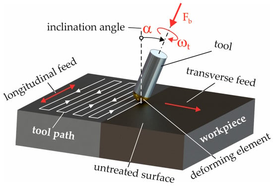
Figure 16.
Kinematic scheme of the SB process, realised in [60].
Shiou and Banh [62] developed an innovative small ball-burnishing tool intended for finishing small flat surfaces (Figure 17). This method involves a spherical-ended deforming element, 0.5 mm in diameter, made of WC or . The kinematic scheme follows Figure 3d. The material being processed is oxygen (O)-free copper (Cu) 101. The authors achieved an average roughness Ra of 0.183 μm when the deforming element was made of .

Figure 17.
Innovative small ball-burnishing tool developed in [62].
Maximov et al. [63] developed a new SB method and tool for improving the SI and fatigue life of a large number of small fastener holes in high-strength Al-alloys using a special burnishing tool, with a K-profile of the working portion shown in cross-section (Figure 18). The kinematics of the method are similar to those of drilling or reaming. The new SB of a hole with a diameter of 8 mm reduces the average roughness Ra from 1.4 µm after reaming to 0.417 µm.

Figure 18.
New burnishing tool [63].
A new method called slide RB (SRB), for the cold working of cylindrical surfaces of metal components on machine tools, implemented with a novel multifunctional device, has been developed by Maximov et al. [64]. The deforming element is a toroidal roller, the axis of which is crossed with the axis of the surface being machined (Figure 19). The workpiece, fixed in a chuck, rotates around its axis with an angular velocity (), and the deforming roller, which is pressed against the surface being machined, rotates around its own axis with an angular velocity () under the action of frictional forces. At the same time, the roller moves parallel to the axis of the workpiece. Thus, the motion of the roller relative to the workpiece is a superposition of rotations about crossed axes and rectilinear translation. The SRB of 316 steel achieved a significant improvement in the SI, providing an average roughness of 0.063 μm, a surface microhardness of 430 HV and a surface axial residual stress of −300 MPa. The improvement over conventional RB is 42% for the Ra and 7% for the microhardness due to the greater surface plastic deformation. Using the same method, Duncheva et al. [65] achieved similar results for 304 steel (Table 5).
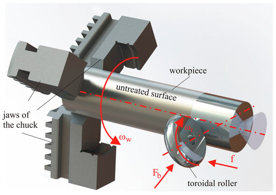
Figure 19.
SRB kinematics.
Shiou et al. [66] designed and fabricated a new load-cell-embedded burnishing tool for implementing SB on a CNC lathe to simplify the control of the burnishing force without using an expensive dynamometer system. Using the kinematic scheme shown in Figure 3a, the authors dramatically improved the SI of hardened SUS420J2 stainless steel, achieving an average roughness of 0.025 μm (the initial Ra was 1.1 μm), an improvement in the surface microhardness of 3%, and a surface residual axial compressive stress of −1030 MPa.
6.2. Effects on Operating Behaviour
The effects of special SB processes on the performance of burnished surfaces have been investigated in several studies [61,63,65]. Okada et al. [61] applied the new SB method using a rotary tool on martensitic stainless steel, heat-treated to create two variants—annealing and quenching and tempering. The authors found that the SB of the annealed steel increased 3-point bending strength and corrosion resistance, evaluated via a salt-spray test. Maximov et al. [63] increased the fatigue strength of 2024-T3 Al alloy specimens with central holes using the new SB method. As can be seen from Figure 20, the increase in fatigue is approximately 50–60%, depending on the stress amplitude. Duncheva et al. [65] determined that the new SRB method improved the roughness of 304 steel specimens compared to conventional RB, while providing the same fatigue strength as RB. In fact, the SRB method results in an anisotropic surface (i.e., an oriented surface texture that depends on the crossing angle). It would be useful, for both practical and scientific reasons, to evaluate the effects of the orientation of the anisotropic surface on the tribological behaviour under boundary lubrication and dry friction conditions.
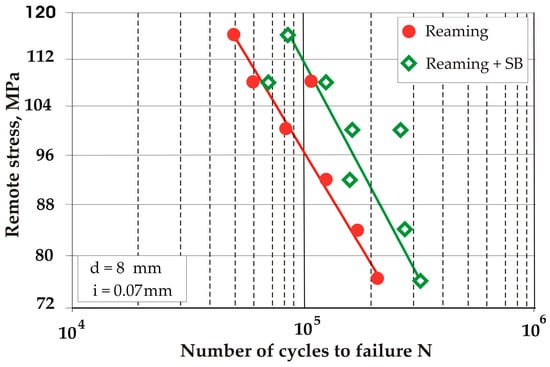
Figure 20.
Effect of SB on fatigue life [63].
7. Hybrid SB Processes
In this review, hybrid SB processes are considered to be those in which two or more impacts are applied simultaneously to the treated surface. They include, for example, ultrasonic-assisted SB (which improves the surface properties of engineering materials by imposing both static and dynamic loads) [67,68,69] and simultaneous laser alloying and SB [70].
The effects of hybrid SB processes on the SI characteristics are summarised in Table 6. The following conclusions can be drawn: (1) too few studies were dedicated to hybrid SB; (2) the processed materials were both steels and non-ferrous alloys; (3) all studies were focused on a comprehensive evaluation of the SI characteristics; and (4) in general, the values achieved for the roughness height parameters were very similar to those obtained by slide diamond burnishing [12].

Table 6.
SI characteristics obtained after hybrid SB processes.
Huuki and Laakso [67] applied ultrasonic-assisted SB under flood lubrication conditions to improve the SI of 34CrNiMo6-M low-alloy structural tempered steel for two hardness variants (330 and 410 HV). The kinematic scheme for this type of SB is consistent with that shown in Figure 3a. The authors reported a drastic improvement in roughness (generally by 90%) and an increase in the residual compressive stresses (400%, on average). However, the surface hardness of the workpiece was not significantly affected.
Ultrasonic-assisted SB was implemented by Teimouri et al. [68] to improve the SI of flat 6061-T6 Al alloy specimens. It was realised in accordance with the kinematic scheme shown in Figure 3d. The authors found that increasing the vibration amplitude from 0 to 10 μm resulted in a 24% improvement in microhardness. The roughness initially reduced by about 15% when the vibration amplitude was increased from 0 to 5 μm, but with a further increase in amplitude, the roughness deteriorated. Simultaneous low roughness (but not minimum) and high microhardness (but not maximum) values were obtained at a vibration amplitude of 8 μm.
Shi et al. [69] designed and manufactured ultrasonic burnishing equipment to significantly improve the SI of austenitic stainless steel rotary specimens. The authors found that the static pressure and burnishing pass were the two most significant governing factors. Superposition with ultrasonic vibrations led to an oscillating propagation of the stress wave inside the material, which explains these results being better than those achieved by SB without ultrasound.
A new hybrid method combining a laser alloying process with SB (both treatments performed on the laser platform in one operation) has been developed and studied by Radziejewska and Skrzypek [70]. The material treated was C45 steel coated with a Co satellite layer. The kinematic scheme of this SB is similar to that shown in Figure 13, except that, instead of four, two spherical-ended deforming elements were used, positioned at different distances from the axis of rotation. Thus, the first deforming element interacts with the alloy layer at a high temperature, smoothing it, while the second element, by interacting with the cooler layer, generates compressive stresses in that layer. The authors found that SB caused grain deformation in a zone with a thickness of 20–30 μm, and increased the surface microhardness to 800 HV0.02. Multiple alloying combined with SB generates compressive residual stresses of about −600 MPa at the surface, which significantly improves the SI.
It should be noted that the cryogenic-assisted SB processes discussed in Section 4 are essentially hybrid, because the treated surface is subjected to both cold working and cryogenic impacts. However, the main motive for developing these processes is the elimination of CF, which is why these processes are primarily sustainable.
8. Combined Processes Involving SB
For this review, the definition we adopted for a combined process was a coordinated sequence of impacts aimed at achieving a synergistic effect on the SI characteristics and operational behaviour of a material. Combined processes involving SB have been investigated in several studies [63,71,72].
Pa [71] developed and studied a combined process that involved successive SB and electrochemical finishing of a bore surface. The cylindrical specimen with a central hole, the surface of which had been machined, was made of SKH57 high-speed tool steel. The kinematic scheme of the SB is shown in Figure 21. The author found that using a high electrolyte flow rate or using a small gap width between the electrode and the workpiece increased the efficiency of the combined process. The effect was greater at a high tool rotation frequency because the dregs discharge the electrochemical machining and facilitate the SB process, increasing its productivity and efficiency. The average roughness Ra achieved was below 0.06 μm.
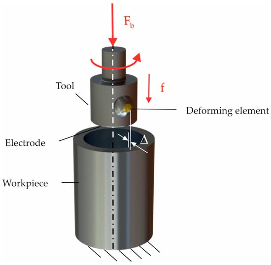
Figure 21.
The kinematic scheme of SB is included in a new combined process [71].
A combined process, including consecutive turning and SB (TSB), was developed by Zhang et al. [72] to improve the SI and stress corrosion resistance of heat-treated 304 and 316L steels. The main idea was that the cutting edge of the tool would remove the material SL as a chip, while the tool corner, with a large radius, would perform an SB process on the manufactured surface. The authors found that TSB significantly improved the resistance to stress corrosion cracking by reducing biaxial residual stresses. The combined stress state of low tensile residual stress in the circumferential direction and compressive residual stress in the axial direction generated by TSB may be responsible for the reduced susceptibility to stress corrosion cracking of austenitic stainless steels. In addition, the multi-pass TSB resulted in better resistance to stress corrosion cracking.
The new SB method and tool for improving the SI and fatigue life of a large number of small fastener holes in high-strength Al alloys [63] can be realised by a super-combined tool (Figure 22), which, in turn, allows this method to be classed as a combined method. This tool significantly increases productivity because it combines drilling, reaming and SB in one operation.

Figure 22.
Supe-combined tool developed in [63].
9. Finite-Element Simulations of SB Process
The finite-element method (FEM) is a powerful tool for studying burnishing processes and, in particular, for obtaining reliable information about the effects of SB on the SI of materials. The most important conditions for building an adequate finite-element (FE) model of a burnishing process have been defined by Maximov et al. [73]: (1) realistic geometries and kinematics of the workpiece-modelled portion and the deforming element; (2) an accurate material constitutive model of the SLs and subsurface layers in the plastic field based on an experiment that corresponds to the actual loading of the workpiece surface and subsurface layers; (3) realistic interactions between the deforming element and the workpiece-modelled portion; (4) adequate geometric, mechanical and physical boundary conditions; and (5) an appropriate FE mesh.
In the SB process, due to the sliding friction contact between the deforming element and the surface being treated, significant friction forces arise. The work of friction forces and plastic deformation is converted into heat, which must be accounted for when creating an adequate FE model. The heat generated causes a softening effect, which changes the stressed and deformed state in the contact zone. At the same time, stresses and deformations affect the heat flux density and its redistribution to the two contacting bodies (the deforming element and surface being treated), resulting in a fully coupled thermal–mechanical process. Therefore, to claim adequacy, among other requirements [73], the FE model of the SB process should be represented as fully coupled 3D thermal stress.
Initial roughness modelling is a mandatory condition because the burnished SL is characterised by severe plastic deformation. However, the roughness profile has a stochastic character, while the FEM generally requires the determined geometry of the integration field. A compromise solution is the initial kinematic roughness obtained after previous turning, which is calculated using Equations (1) and (2). A more accurate solution would be to scan the roughness micro-profile of a machined specimen and import the information into the FE model [74].
The construction of an adequate constitutive model of the material of the SLs of the workpiece is a mandatory condition for the adequacy of the FE model. The mechanical behaviour of the SLs differs from that of the bulk material due to the presence of large plastic strains, specific micro-profiles, microstructure due to the workpiece production and other effects. Thus, the conventional testing methods for stress–strain curve determination, using a 1D compressive or tensile test, are not suitable for the surface and subsurface layers. The stress–strain dependence in the plastic field of the surface and subsurface layers should be determined based on the actual loading of these layers. Therefore, an approach based on indentation tests and inverse FE analyses [15,75,76] is very suitable. An important element in the constitutive model is the type of strain hardening. Each burnishing process causes cyclic loading of the SLs and nearby subsurface layers. This causes a displacement of the yield surface in the stress space, which is accounted for by the back-stress tensor in a kinematic hardening model.
The sliding friction coefficient between the deforming element and the surface being treated is an important characteristic for an adequate FE model. In Maximov et al. [77], a theoretical–experimental method for determining this coefficient was developed, which actually depends on all governing factors and on the initial roughness. The advantage of this method is that the determined friction coefficient actually records the heat generated by the plastic deformation.
Three groups of boundary conditions exist in the SB FE model—geometric, mechanical and physical (thermal). The first two groups provide the actual relative motion between the workpiece modelled portion and the deforming element. The third group defines the heat generated by the friction and plastic deformation, and the heat transfer.
In the burnishing processes, a very high strain gradient is generated in the normal direction. Therefore, a very fine mesh near the surface being treated should be built. It should be noted that the sizes of the FEs on the surface must be consistent with the description of the initial roughness. Because the at-depth material remains unaffected, the FE mesh in the direction of the core should be coarser.
A fully coupled thermal–stress FE analysis significantly increases the computational time. The most common simplification of the 3D FE model is to ignore the thermal effect. The heat flux density generated by the sliding friction increases proportionally to the burnishing velocity [73]. Thus, simplification of the FE model is justified when the velocity is below 60–80 m/min and the temperature effect can be ignored. Further simplification of the 3D FE model by replacing the actual kinematics with ‘load–unload–feed’ cycles leads to unsatisfactory results. For example, 2D simplified FE models show a drastic difference (sometimes up to 300%) in the residual surface stress results compared to X-ray diffraction results [73].
Several FE studies of SB processes have been conducted [37,53,57,63,68,69], and their summary information is presented in Table 7 and Table 8. The following conclusions can be drawn: (1) too few studies have used the FEM as a research tool; (2) given the thermo-mechanical nature of the SB process, all FE models have been simplified to varying degrees; (3) simplifications have included replacing the real 3D object with a 2D FE model, ignoring the fully coupled thermal–stress effect, replacing the real kinematics with a simpler one and neglecting the initial roughness; (4) temperature has been included to the extent that the Johnson–Cook material model has been used; (5) initial roughness was considered in only two of the models; and (6) regardless of the cyclical nature of the loading of the SL during the SB process, the majority of models use the isotropic hardening model.

Table 7.
General characteristics of the FE models used.

Table 8.
Characteristics of the material constitutive model.
10. Theoretical Investigation of the SB Process
Only one theoretical study has been devoted to the nature of the SB process. Paszta et al. [78] presented an analytical model based on Belyaev’s theory for determining the depth of the plastically deformed upper layer in the SB process. The object of analysis was the SB (using a spherical-ended deforming element) of shafts with a diameter of 48 mm, made of steel with yield limit (Re) values of 450 and 900 MPa. The authors found that the relationship between the depth (δ) of the plastically deformed top layer and the contact force (F) can be presented by the power equation , where u and h are constants.
11. Conclusions and Perspectives Concerning SB Processes
Our literature survey confirms the potential of the SB process with non-diamond-based deforming elements to significantly improve the SI and operating behaviour of a wide range of materials and structural components. Based on our critical analysis of SB processes implemented using non-diamond-based deforming elements, we have been able to outline perspectives for the development of this type of finishing, as follows:
- There is a lack of information on the SB of super-alloys (for instance, GH4169, Inconel 718), bronzes, wear-resistant (manganese [Mn]) steels and cast iron alloys. Very few studies have been devoted to titanium (Ti) alloys. There has also been little research on the effects of SB on the SI and operating behaviour of cooper-based alloys. There is a lack of research on the SB of additively manufactured materials. Filling these gaps would be a promising direction for the development of SB.
- Given the very small number of studies, a promising direction is the SB of holes and flat and complex surfaces.
- The effects of SB on the SI of materials have been studied significantly more than the effects of this process on the operating behaviour of the machined component. The simple correlation between the SI and the operating behaviour has been studied much less frequently (the fewest studies were those focused on fatigue behaviour). Only one study investigated the SB–SI–operating behaviour correlation. Establishing this complete correlation is a prerequisite for developing cost-effective SB processes based on optimisation procedures for a specific material and application. The implementation of this integrated approach will improve the cost/quality ratio, providing added value.
- Sustainability issues are becoming increasingly important in all industries. Our review showed that SB is no exception to this trend, given the harmful effects of CFs (used in conventional SB) on human health and the environment. Expanding this research to include more materials is a particularly promising direction. For a process to be sustainable, it must fulfil three key demands–economic, environmental and social. Therefore, dry, cool-assisted and cryogenic-assisted SB processes are sustainable. The use of MQL partially reduces pollution and lubrication costs, but does not improve working conditions (the social aspect), due to the oil mist formed during its application, which cannot be completely eradicated and is the cause of numerous diseases. Therefore, the MQL-assisted SB process cannot be classed as a sustainable SB process because it occupies an intermediate (hybrid) position between conventional and sustainable processes.
- Hybrid and combined SB processes have significant potential for achieving a synergistic effect to improve the SI and operating behaviour of metal components. Particularly promising are the processes that combine thermal and chemical diffusion and SB, or the effects of concentrated energy flows (electron beam, laser beam and others) and SB. Such approaches combine the advantages of two effects—transformation hardening and strain hardening. As of writing, no such studies are available. Filling this gap will significantly expand the area of SB applications.
- Hybrid processes require simultaneous impacts on the treated surface, one of which has a dominant role (surface cold working), while the others perform an assisting function. So far, hybrid SB processes have been limited to the ultrasonic-assisted and cryogenic-assisted types. The development of hybrid SB processes to help with other types of assisting impacts (e.g., laser-assisted SB) will have useful scientific and practical ramifications.
- The development of super-hard materials for the manufacture of deforming elements, and the study of their tribological behaviour (as pairs with counterbodies made of different materials) is a prerequisite for expanding the scope of application of SB processes.
- The level of development of modern information technologies allows the use of artificial intelligence and machine learning to optimise and synthesise new SB processes.
- Given the increasing application of additively manufactured and composite structures, another perspective is the optimisation of existing and new SB processes in connection with modelling the mechanical behaviour (including fatigue) of such structures.
Author Contributions
Conceptualisation, J.M. and G.D.; methodology, J.M. and G.D.; software, J.M. and G.D.; validation, J.M. and G.D.; formal analysis, J.M. and G.D.; investigation, J.M. and G.D.; resources, J.M. and G.D.; data curation, J.M. and G.D.; writing—original draft preparation, J.M. and G.D.; writing—review and editing, J.M. and G.D.; visualisation, J.M. and G.D.; supervision, J.M.; project administration, J.M. and G.D.; funding acquisition, J.M. and G.D. All authors have read and agreed to the published version of the manuscript.
Funding
This research was funded by the European Regional Development Fund under the Operational Programme “Scientific Research, Innovation and Digitization for Smart Transformation 2021–2027”, Project CoC “SmartMechatronics, Eco- and Energy Saving Systems and Technologies”, BG16RFPR002-1.014-0005.
Institutional Review Board Statement
Not applicable.
Informed Consent Statement
Not applicable.
Data Availability Statement
The original contributions presented in the study are included in the article; further inquiries can be directed to the corresponding author.
Conflicts of Interest
The authors declare no conflicts of interest.
Abbreviations
| CF | cutting fluid |
| CNC | computer numerical control |
| FE | finite element |
| FEM | finite-element method |
| MQL | minimum quantity lubrication |
| RB | roller burnishing |
| SB | slide burnishing |
| SE | surface engineering |
| SI | surface integrity |
| SL | surface layer |
| SMB | spherical motion burnishing |
| SRB | slide roller burnishing |
| TSB | turning and slide burnishing |
| WC | tungsten carbide |
References
- Dwivedi, D.K. Surface Engineering. In Enhancing Life of Tribological Components; Springer: New Delhi, India, 2018; ISBN 978-81-322-3779-2. [Google Scholar]
- Miranda, R.M.; Gabdra, J.; Vilaca, P.; Quintino, L. Surface Modification by Solid State Processing; Elsevier: Amsterdam, The Netherlands; Woodhead Publishing: New Delhi, India, 2018; ISBN 978-0-85709-469-8. [Google Scholar]
- Burakowski, T.; Wierzchon, T. Surface Engineering of Metals: Principles, Equipment, Technologies; CRC Press: Boca Raton, FL, USA, 1998; ISBN 0-8493-8225-4. [Google Scholar]
- Plaster, H.J. A tribute to Benjamin Chew Tilghman. In Proceedings of the 5th International Conference on Shot Peening, Oxford, UK, 13–17 September 1993; pp. 2–9. [Google Scholar]
- Lawerenz, M. Shot Peening and its Effect on Gearing. In SAE Technical Paper 841090; SAE Mobilus: Warrendale, PA, USA, 1984. [Google Scholar] [CrossRef]
- Yang, J.M.; Her, Y.C.; Han, N.; Clauer, A. Laser shock peening on fatigue behavior of 2024–T3 Al alloy with fastener holes and stopholes. Mater. Sci. Eng. A 2001, 298, 296–299. [Google Scholar] [CrossRef]
- Soyama, H. Cavitation peening: A review. Metals 2020, 10, 270. [Google Scholar] [CrossRef]
- Soyama, H. Oxidation-induced stacking faults introduced by using a cavitating jet for gettering in silicon. Electrochem. Solid-State Lett. 1999, 3, 93–94. [Google Scholar] [CrossRef]
- Wegener, T.; Wu, T.; Sun, F.; Wang, C.; Lu, J.; Niendorf, T. Influence of surface attrition treatment (SMAT) on microstructure, tensile and low-cycle fatigue behaviour of additively manufactured stainless steel 316L. Metals 2022, 12, 1425. [Google Scholar] [CrossRef]
- Galda, L.; Koszela, W.; Pawlus, P. Surface geometry of slide bearings after percussive burnishing. Tribol. Int. 2007, 40, 1516–1525. [Google Scholar] [CrossRef]
- Hull, E.H.; Nerad, A.J. Irregular Diamond Burnishing Tool. U.S. Patent 2966722, 3 January 1961. [Google Scholar]
- Maximov, J.T.; Duncheva, G.V. Effects of diamond burnishing on surface integrity, fatigue, wear, and corrosion of metal components—Review and perspectives. Int. J. Adv. Manuf. Technol. 2025, 139, 4233–4267. [Google Scholar] [CrossRef]
- Korzynski, M. Slide diamond burnishing. In Nonconventional Finishing Technologies; Korzynski, M., Ed.; Polish Scientific Publishers PWN: Warsaw, Poland, 2013; pp. 9–34. [Google Scholar]
- Maximov, J.; Duncheva, G. The Correlation between Surface Integrity and Operating Behaviour of Slide Burnished Components—A Review and Prospects. Appl. Sci. 2023, 13, 3313. [Google Scholar] [CrossRef]
- Yen, Y.C.; Sartkulvanich, P.; Altan, T. Finite element modeling of roller burnishing process. CIRP Ann.-Manuf. Technol. 2005, 54, 237–240. [Google Scholar] [CrossRef]
- Nestler, A.; Schubert, A. Effect of machining parameters on surface properties in slide diamond burnishing of aluminium matrix composites. Mater. Today Proc. 2015, 2S, S156–S161. [Google Scholar] [CrossRef]
- Maximov, J.T. Spherical Motion Burnishing. In Nonconventional Finishing Technologies; Korzynski, M., Ed.; Polish Scientific Publishers PWN: Warsaw, Poland, 2013; pp. 35–59. [Google Scholar]
- Adler, D.P.; Hii, W.W.-S.; Michalek, D.J.; Sutherland, J.W. Examining the role of cutting fluids in machining and efforts to address associated environmental/health concerns. Mach. Sci. Technol. 2006, 10, 23–58. [Google Scholar] [CrossRef]
- Elsner, P.; Wilhelm, D.; Maibach, H.I. Irritant Contact Dermatitis irritant contact dermatitis and aging. Contact Dermat. 1990, 23, 275. [Google Scholar] [CrossRef]
- Mackerer, C.R. Health effects of oil mists: A brief review. Toxicol. Ind. Health 1989, 5, 429–440. [Google Scholar] [CrossRef] [PubMed]
- Jawahir, I.S.; Attia, H.; Biermann, D.; Duflou, J.; Klocke, F.; Meyer, D.; Newman, S.T.; Pusavec, F.; Putz, M.; Rech, J.; et al. Cryogenic manufacturing processes. CIRP Ann.-Manuf. Technol. 2016, 65, 713–736. [Google Scholar] [CrossRef]
- Maximov, J.M.; Duncheva, G.V. Effects of Cryogenic- and Cool-Assisted Burnishing on the Surface Integrity and Operating Behaviour of Metal Components: A Review and Perspectives. Machines 2024, 12, 312. [Google Scholar] [CrossRef]
- Lin, Y.C.; Wang, S.W.; Lai, H.Y. The relationship between surface roughness and burnishing factor in the burnishing process. Int. J. Adv. Manuf. Technol. 2004, 23, 666–671. [Google Scholar] [CrossRef]
- Shiou, F.J.; Chen, C.H. Determination of optimal ball-burnishing parameters for plastic injection moulding steel. Int. J. Adv. Manuf. Technol. 2003, 21, 177–185. [Google Scholar]
- Dzierwa, A.; Galda, L.; Tupaj, M.; Dudek, K. Investigation of wear resistance of selected materials after slide burnishing process. Maint. Reliab. 2020, 22, 432–439. [Google Scholar] [CrossRef]
- Dyl, T.; Wijata, M.; Kuśmierska-Matyszczak, W. The slide broaching burnishing and the influence of deformation on roughness of 314L stainless steel sleeves. Sci. J. Gdyn. Marit. Univ. 2020, 116, 15–28. [Google Scholar] [CrossRef]
- Elsamanty, M.; Youssef, W.F.; Abdelsalam, M.; Ibrahim, A.A. Investigating the influence of tool selection on surface quality in burnished AISI 1035 steel. Eng. Res. J. 2024, 53, 130–141. [Google Scholar] [CrossRef]
- Roohi, H.; Baseri, H.; Mirnia, M.J. Evaluation of optimized surface characteristics in non-rotational sliding ball burnishing. Mater. Manuf. Process. 2024, 39, 2299–2308. [Google Scholar] [CrossRef]
- Roohi, H.; Baseri, H.; Mirnia, M.J. Experimental study of slide burnishing process of the pre-milled AA7075 Plate: Surface topography and hardening aspects. Arab. J. Sci. Eng. 2024, 50, 18403–18423. [Google Scholar] [CrossRef]
- Jacobson, B. The Stribeck memorial lecture. Tribol. Int. 2003, 36, 781–789. [Google Scholar] [CrossRef]
- Hersey, M.D. The laws of lubrication of horizontal journal bearings. J. Wash. Acad. Sci. 1914, 4, 542–552. [Google Scholar]
- Buldum, B.B.; Cagan, S.C. Study of Ball Burnishing Process on the Surface Roughness and Microhardness of AZ91D Alloy. Exp. Tech. 2018, 42, 233–241. [Google Scholar] [CrossRef]
- Esme, U. Use of grey based Taguchi method in ball burnishing process for the optimization of surface burnishing and microhardness of AA7075 aluminium alloy. Mater. Technol. 2010, 44, 129–135. [Google Scholar]
- Kato, H.; Yamamoto, K.; Yasunaga, K. Nano-crystallization of steel surface by slide-burnishing. Key Eng. Mater. 2020, 841, 48–53. [Google Scholar] [CrossRef]
- Kato, H.; Hirokawa, W.; Todaka, Y.; Yasunaga, K. Improvement in surface roughness and hardness for carbon steel by slide burnishing process. Mater. Sci. Appl. 2021, 12, 171–181. [Google Scholar] [CrossRef]
- Bobrovskij, I.; Bobrovskij, N.; Khaimanovich, A.; Travieso-Rodriguez, J.A. Impacts of surface texture and nature of friction on energy-force efficiency of surface plastic deformation during burnishing. Metals 2022, 12, 1568. [Google Scholar] [CrossRef]
- Kuznetsov, V.; Smolin, I.; Skorobogatov, A.; Akhmetov, A. Finite element simulation and experimental investigation of nanostructuring burnishing AISI 52100 steel using an inclined flat cylindrical tool. Appl. Sci. 2023, 13, 5324. [Google Scholar] [CrossRef]
- Rachmat, H.; Mahalil, K.; Mohid, Z.; Rahim, E.A. Comparison between Dry, MQL, and Cryogenic Cooling Technique on Surface Integrity of Burnished Surface. Int. J. Integr. Eng. 2019, 11, 35–41. [Google Scholar] [CrossRef]
- Rachmat, H.; Rahim, E.A.; Mohid, Z.; Mahalil, K.; Kasah, A.A.; Nadzri, A. Effect of Burnishing Tool Diameter and Coolant Strategies on Burnishing Performance. IOP Conf. Ser. J. Phys. Conf. Ser. 2019, 1150, 012070. [Google Scholar] [CrossRef]
- Mahalil, K.; Rahim, E.A.; Mohid, Z. Performance Evaluation of Sustainable Coolant Techniques on Burnishing Process. IOP Conf. Ser. Mater. Sci. Eng. 2019, 494, 012001. [Google Scholar] [CrossRef]
- Pu, Z.; Song, G.L.; Yang, S.; Dillon, O.W., Jr.; Puleo, D.A.; Jawahir, I.S. Cryogenic Burnishing of AZ31B Mg Alloy for Enhanced Corrosion Resistance. In Magnesium Technology; TMS (The Minerals, Metals & Materials Society): Pittsburgh, PA, USA, 2011; pp. 513–518. [Google Scholar]
- Pu, Z.; Yang, S.; Song, G.L.; Dillon, O.W., Jr.; Puleo, D.A.; Jawahir, I.S. Ultrafine-grained surface layer on Mg-Al-Zn alloy produced by cryogenic burnishing for enhanced corrosion resistance. Scr. Mater. 2011, 65, 520–523. [Google Scholar] [CrossRef]
- Pu, Z.; Song, G.-L.; Yang, S.; Outeiro, J.C.; Dillon, O.W.; Puleo, D.A.; Jawahir, I.S. Grain refined and basal textured surface produced by burnishing for improved corrosion performance of AZ31B Mg alloy. Corros. Sci. 2012, 57, 192–201. [Google Scholar] [CrossRef]
- Pu, Z. Cryogenic Machining and Burnishing of AZ31B Magnesium Alloy for Enhanced Surface Integrity and Functional Performance. Ph.D. Thesis, University of Kentucky, Lexington, KY, USA, 2012. [Google Scholar]
- Singh, P.; Kumar, P.; Virdi, R.L. Effect of In-process Cryogenic Cooling in the Burnishing Process on the Solid Particle Erosion Behavior of HVOF Cermet Coating. J. Therm. Spray Technol. 2023, 32, 2068–2080. [Google Scholar] [CrossRef]
- Tang, J.; Luo, H.Y.; Zhang, Y.B. Enhancing the surface integrity and corrosion resistance of Ti–6Al–4V titanium alloy through cryogenic burnishing. Int. J. Adv. Manuf. Technol. 2017, 88, 2785–2793. [Google Scholar] [CrossRef]
- Tang, J.; Luo, H.; Qi, Y.; Xu, P.; Ma, S.; Zhang, Z.; Ma, Y. The effect of cryogenic burnishing on the formation mechanism of corrosion product film of Ti–6Al–4V titanium alloy in 0.9% NaCl solution. Surf. Coat. Technol. 2018, 345, 123–131. [Google Scholar] [CrossRef]
- Yang, S.; Pu, Z.; Puleo, D.; Dillon, O.W.; Jawahir, I.S. Cryogenic Processing of Biomaterials for Improved Surface Integrity and Product Sustainability. In Advances in Sustainable Manufacturing; Springer: Berlin/Heidelberg, Germany, 2011; pp. 177–182. [Google Scholar]
- Yang, S.; Puleo, D.; Dillon, O.W., Jr.; Jawahir, I.S. Surface Layer Modifications in Co-Cr-Mo Biomedical Alloy from Cryogenic Burnishing. Procedia Eng. 2011, 19, 383–388. [Google Scholar] [CrossRef]
- Yang, S.; Dillon, O.W., Jr.; Puleo, D.A.; Jawahir, I.S. Effect of cryogenic burnishing on surface integrity modifications of Co–Cr–Mo biomedical alloy. J. Biomed. Mater. Res. B Appl. Biomater. 2013, 101, 139–152. [Google Scholar] [CrossRef]
- Yang, S.; Umbrello, D.; Dillon, O.W., Jr.; Puleo, D.; Jawahir, I.S. Cryogenic cooling effect on surface and subsurface microstructural modifications in burnishing of Co–Cr–Mo biomaterial. J. Mater. Process. Technol. 2015, 217, 211–221. [Google Scholar] [CrossRef]
- Yang, S.; Dillon, O.W., Jr.; Puleo, D.A.; Jawahir, I.S. Enhancement of wear resistance for improved functional performance of Co-Cr-Mo hip implants through cryogenic surface treatment: A case study. Mach. Sci. Technol. 2021, 25, 455–476. [Google Scholar] [CrossRef]
- Yang, S.; Umbrello, D.; Dillon, O.W., Jr.; Jawahir, I.S. Numerical Investigation of Dynamic Recrystallization Induced Microstructural Evolution in Cryogenic Burnishing of Co-Cr-Mo Biomaterial. J. Mater. Eng. Perform. 2022, 31, 6904–6921. [Google Scholar] [CrossRef]
- Yang, S. Cryogenic Burnishing of Co-Cr-Mo Biomedical Alloy for Enhanced Surface Integrity and Improved Wear Performance. Ph.D. Thesis, University of Kentucky, Lexington, KY, USA, 2012. [Google Scholar]
- Cagan, S.C.; Tasci, U.; Pruncu, C.I.; Bostan, B. Investigation of the effects of eco-friendly MQL system to improve the mechanical performance of WE43 magnesium alloys by the burnishing process. J. Braz. Soc. Mech. Sci. Eng. 2023, 45, 22. [Google Scholar] [CrossRef]
- Gharbi, F.; Sghaier, S.; Hamdi, H.; Benameur, T. Ductility improvement of aluminum 1050A rolled sheet by a newly designed ball burnishing tool device. Int. J. Adv. Manuf. Technol. 2012, 60, 87–99. [Google Scholar] [CrossRef]
- Maximov, J.T.; Duncheva, G.V. Finite Element Analysis and optimization of spherical motion burnishing of low-alloy steel. Proc. IMechE Part C J. Mech. Eng. Sci. 2012, 226, 161–176. [Google Scholar] [CrossRef]
- Maximov, J.T.; Duncheva, G.V.; Amudjev, I.M.; Kuzmanov, T.V. Modelling the power parameters of the spherical motion burnishing. Proc. IMechE Part C J. Mech. Eng. Sci. 2012, 226, 498–510. [Google Scholar] [CrossRef]
- Maximov, J.T.; Kuzmanov, T.V.; Duncheva, G.V.; Ganev, N. Spherical motion burnishing implemented on lathes. Int. J. Mach. Tools Manuf. 2009, 49, 824–831. [Google Scholar] [CrossRef]
- Okada, M.; Terada, S.; Miura, T.; Iwai, Y.; Takazawa, T.; Kataoka, Y.; Kihara, T.; Otsu, M. Fundamental burnishing characteristics of Ni-based alloy using coated carbide tool. Procedia Manuf. 2018, 15, 1278–1283. [Google Scholar] [CrossRef]
- Okada, M.; Terada, S.; Kataoka, Y.; Kihara, T.; Miura, T.; Otsu, M. Burnishing characteristics of sliding burnishing process with active rotary tool targeting stainless steel. J. Adv. Mech. Des. Syst. Manuf. 2021, 15, JAMDSM0044. [Google Scholar] [CrossRef]
- Shiou, F.J.; Banh, Q.N. Development of an innovative small ball-burnishing tool embedded with a load cell. Int. J. Adv. Manuf. Technol. 2016, 87, 31–41. [Google Scholar] [CrossRef]
- Maximov, J.T.; Duncheva, G.V.; Anchev, A.P.; Amudjev, I.M. New method and tool for increasing fatigue life of a large number of small fastener holes in 2024-T3 Al-alloy. J. Braz. Soc. Mech. Sci. Eng. 2019, 41, 203. [Google Scholar] [CrossRef]
- Maximov, J.M.; Duncheva, G.V.; Anchev, A.P.; Dunchev, V.P.; Anastasov, K.; Daskalova, P.H. Effect of Roller Burnishing and Slide Roller Burnishing on Surface Integrity of AISI 316 Steel: Theoretical and Experimental Comparative Analysis. Machines 2024, 12, 51. [Google Scholar] [CrossRef]
- Duncheva, G.V.; Maximov, J.T.; Anchev, A.P.; Dunchev, V.P.; Anastasov, K.; Argirov, Y.B. Effect of roller burnishing and slide roller burnishing on fatigue strength of AISI 304 steel: Comparative analysis. Metals 2024, 14, 710. [Google Scholar] [CrossRef]
- Shiou, F.J.; Huang, S.J.; Shin, A.J.; Zhu, J.; Yoshino, M. Fine Surface Finish of a Hardened Stainless Steel Using a New Burnishing Tool. Procedia Manuf. 2017, 10, 208–217. [Google Scholar] [CrossRef]
- Huuki, J.; Laakso, S.V.A. Integrity of surface finished with ultrasonic burnishing. Proc. IMechE Part B J. Eng. Manuf. 2013, 227, 45–53. [Google Scholar] [CrossRef]
- Teimouri, R.; Amini, S.; Bami, A.B. Evaluation of optimized surface properties and residual stress in ultrasonic assisted ball burnishing of AA6061-T6. Measurement 2018, 116, 129–139. [Google Scholar] [CrossRef]
- Shi, Y.; Shen, X.; Xu, G.; Xu, C.; Wang, B.; Su, G. Surface integrity enhancement of austenitic stainless steel treated by ultrasonic burnishing with two burnishing tips. Arch. Civ. Mech. Eng. 2020, 20, 79. [Google Scholar] [CrossRef]
- Radziejewska, J.; Skrzypek, S. Microstructure and residual stresses in surface layer of simultaneously laser alloyed and burnished steel. J. Mater. Process. Technol. 2009, 209, 2047–2056. [Google Scholar] [CrossRef]
- Pa, P.S. Continuous finishing processes using a combination of burnishing and electrochemical finishing on bore surface. Int. J. Adv. Manuf. Technol. 2010, 49, 147–154. [Google Scholar] [CrossRef]
- Zhang, W.; Dong, H.; Li, H.; Yang, C.; Xue, H. Combining turning with slide burnishing to improve surface integrity and stress corrosion resistance. J. Manuf. Process. 2023, 107, 16–33. [Google Scholar] [CrossRef]
- Maximov, J.T.; Duncheva, G.V.; Dunchev, V.P.; Anchev, A.P. Different strategies for finite element simulations of static mechanical surface treatment processes—A comparative analysis. J. Braz. Soc. Mech. Sci. Eng. 2021, 43, 371. [Google Scholar] [CrossRef]
- Borysenko, D.; Welzel, F.; Karpuschewski, B.; Kundrák, J.; Voropai, V. Simulation of the burnishing process on real surface structures. Precis. Eng. 2021, 68, 166–173. [Google Scholar] [CrossRef]
- Dunchev, V.; Peneva, P. Temperature-dependent constitutive model of the surface layer of 2024-T3 aluminium alloy subjected to surface plastic deformation. J. Tech. Univ. Gabrovo 2020, 60, 79–85. [Google Scholar]
- Sartkulvanich, P.; Altan, T.; Jasso, F.; Rodriguez, C. Finite element modeling of hard roller burnishing: An analysis on the effects of process parameters upon surface finish and residual stresses. J. Manuf. Sci. Eng. 2007, 129, 705–716. [Google Scholar] [CrossRef]
- Maximov, J.T.; Anchev, A.P.; Duncheva, G.V. Modeling of the friction in tool-workpiece system in diamond burnishing process. Coupled Syst. Mech. 2015, 4, 279–295. [Google Scholar] [CrossRef]
- Paszta, P.; Chalko, L.; Kowalik, R. Assesment of the depth of the plastically deformed top layer in burnishing process of shaft using a ceramic tool. Adv. Mech. Mater. Eng. 2024, 41, 47–55. [Google Scholar]
Disclaimer/Publisher’s Note: The statements, opinions and data contained in all publications are solely those of the individual author(s) and contributor(s) and not of MDPI and/or the editor(s). MDPI and/or the editor(s) disclaim responsibility for any injury to people or property resulting from any ideas, methods, instructions or products referred to in the content. |
© 2025 by the authors. Licensee MDPI, Basel, Switzerland. This article is an open access article distributed under the terms and conditions of the Creative Commons Attribution (CC BY) license (https://creativecommons.org/licenses/by/4.0/).