Review

A Review of Challenges and Future Perspectives for High-Speed Material Extrusion Technology

1
School of Mechanical Engineering, Hubei University of Technology, Wuhan 430068, China
2
Hubei Key Laboratory of Modern Manufacture Quality Engineering, School of Mechanical Engineering, Hubei University of Technology, Wuhan 430068, China
*
Author to whom correspondence should be addressed.
Appl. Sci. 2025, 15(22), 12176; https://doi.org/10.3390/app152212176
Submission received: 18 October 2025 / Revised: 7 November 2025 / Accepted: 11 November 2025 / Published: 17 November 2025
(This article belongs to the Special Issue Feature Review Papers in Additive Manufacturing Technologies)

Abstract

Additive manufacturing, as an innovative manufacturing technology compared to traditional subtractive manufacturing, offers greater design freedom and rapid prototyping capabilities. Material Extrusion (MEX), the most widely applied branch within additive manufacturing (AM), operates on the core principle of heating thermoplastic polymers or composite materials to a molten state, then depositing them layer by layer through a nozzle to form the final shape. However, the inherent contradiction between printing speed and build quality remains the key bottleneck limiting its widespread adoption. Desktop Material Extrusion techniques like Fused Filament Fabrication (FFF) offer high precision but require extended printing times. Meanwhile, industrial-scale Big Area Additive Manufacturing (BAAM) processes achieve high deposition rates yet suffer from insufficient accuracy. This paper systematically reviews the primary application domains of additive manufacturing technologies, elucidating their process flows and classification systems. Building upon this foundation, it systematically analyzes the contradiction and coupling relationship between high precision and high deposition speed in Material Extrusion technologies from aspects including hot-end flow, system thermal management, vibration, and printing parameters. It provides a reference for the subsequent design and optimization of high-precision, high-speed Material Extrusion (MEX) printers.

1. Introduction

In recent years, as the development of the manufacturing industry has progressed rapidly, the limits of traditional manufacturing methods have grown increasingly evident. For example, subtractive manufacturing technologies (milling, drilling, grinding, etc.) generate a significant amount of material waste. The use of mold for subtractive manufacturing processes (casting, forging, stamping, etc.) leads to a long manufacturing cycle and high cost. It is not easy to adapt to dynamic market adjustments.
The manufacturing capacity of complex and irregular structures is limited, and the manufacturing freedom is low [1,2]. Compared to traditional subtractive manufacturing, additive manufacturing (AM) technologies can fabricate products with more complex geometries, generate less material waste, and achieve shorter production cycles. It demonstrates that AM technology has a significant potential in customized production and complex structural manufacturing [3,4]. In the future, industry manufacturing will center on AM technology and increase manufacturing efficiency, freedom, and adaptability.
To address the limitations of existing reviews on high-speed materials—which are often organized in a modular and descriptive manner while lacking cross-domain coupling—this paper proposes an optimization framework centered on high speed. Within this framework, flow behavior, thermal management, vibration, resolution, and mechanical strength are analyzed and compared synergistically under a unified scaling system. Unlike previous studies that primarily focused on materials, monitoring, or single-parameter optimization, the scope of this work extends from nozzle/channel rheology to environmental and platform dynamics and further to path and infill design. On this basis, a co-optimization roadmap and practical guideline tailored to high-speed MEX (Material Extrusion Additive Manufacturing) are distilled and presented.

1.1. Application Fields of Additive Manufacturing Technologies

AM enables the monolithic fabrication of complex components, as it eliminates the reliance on molds and design constraints associated with traditional subtractive manufacturing [5,6]. Hence, it is widely used in different fields, including the automotive, medical, architecture, and aerospace fields.

1.1.1. Automotive Field

AM technologies, by virtue of their layer-by-layer stacking of manufacturing characteristics, can manufacture complex topologies. It has become an important direction of the automotive industry. At present, many enterprises and engineers are applying AM technologies to manufacture automotive components, which allows for lighter and more complex products in a short amount of time. For example, Pokkalla et al. [7] proposed the Additive Manufacturing–Compression Molding (AM–CM) process for fabricating automotive seatbacks. In this approach, a CF/PA66 composite preform is first produced by Big Area Additive Manufacturing (BAAM) and then mechanically interlocked with 316L metal inserts—fabricated via Binder Jetting—through compression molding. The resulting hybrid component achieves an approximately 20% weight reduction while maintaining structural stiffness. The specific process is illustrated in Figure 1. First, 316L stainless-steel metal inserts are fabricated using Binder Jetting (Figure 1a). Next, a carbon fiber-reinforced polyamide composite preform is produced via Big Area Additive Manufacturing (BAAM) (Figure 1b). Finally, the metal inserts are placed into a mold, and the printed polymer composite is heated to 343 °C and positioned on top. Under a pressure of 70 tons for approximately one minute, the molten polymer flows into the mesh pores of the metal insert, forming a mechanically interlocked interface (Figure 1c). In addition, functional components can also be fabricated directly using the Material Extrusion (MEX) process. Garmabi et al. [8] demonstrated that, by optimizing nozzle temperature, layer height, and chamber temperature during Fused Filament Fabrication (FFF) of polyphenylene sulfide (PPS), the interlayer bonding was significantly enhanced, enabling the printed specimens to reach 93% of the tensile strength and 96% of the modulus of compression-molded PPS. Under these optimized conditions, an automotive coolant inlet pipe was printed; after immersion for two weeks in automotive chemical media, the mass change was less than 1%, and the tensile strength decreased by about 5%, indicating promising service performance for automotive applications.
Meanwhile, Andreozzi et al. [9] utilized FFF to fabricate short carbon fiber-reinforced PA6 composite molds for producing carbon fiber-reinforced polymer (CFRP) stiffeners used in racing car winglets. Finite element analysis confirmed that no overloading occurred under bolt pre-tightening, and the overall environmental impact of the entire process was reduced by approximately 18% compared with aluminum molds. These results demonstrate the economic and environmental advantages of MEX tooling for small-batch or customized CFRP automotive parts. Furthermore, Fedulov et al. [10] proposed a topology optimization framework for continuous fiber 3D printing, ensuring smooth variation in fiber orientation. The approach was applied to optimize a racing pedal support structure, and manufacturability and toolpath strategies were experimentally validated through solid MEX printing of continuous fiber composites.

1.1.2. Medical Field

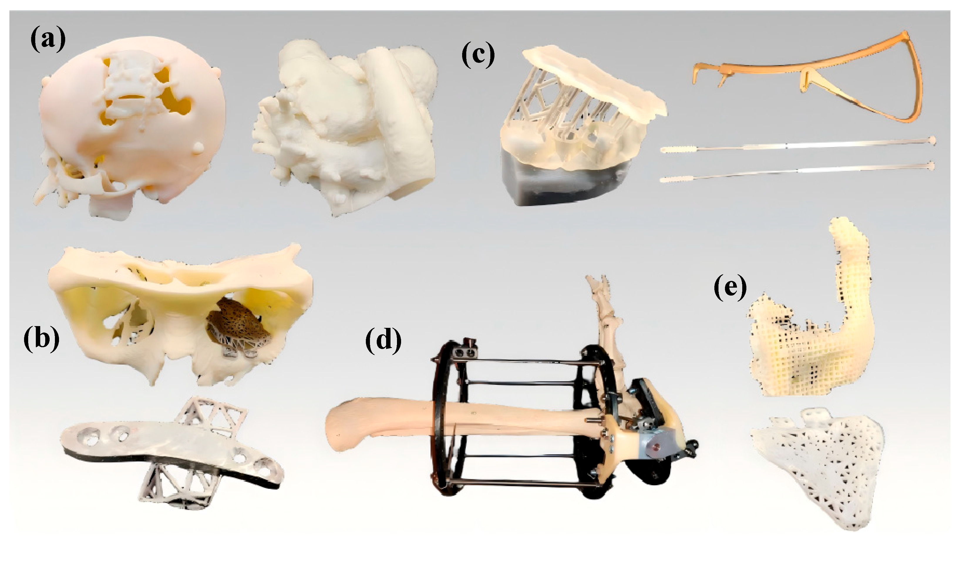
Additive manufacturing technology can also be used in the medical field due to its capacities of precise fabrication of diverse complex structures, for example, orthopedics, dentistry, instruments of diagnostics and surgery, artificial limbs, customized medical implants, and microfluidic techniques, etc. [11,12]. Examples of additive manufacturing applications in the medical field are shown in Figure 2 below.
Numerous scholars and research institutions have carried out extensive studies on this issue. For example, Germaini [13] presented a comprehensive evaluation of different materials and AM processes. In addition, four types of AM processes for bone tissue engineering were analyzed, including extrusion-based material, stereolithography, selective laser sintering, and inkjet 3D printing.
Additive manufacturing has been widely applied in diagnostic and surgical instruments due to the low cost and high customizability of polymer materials used in Material Extrusion processes [14]. Zekraoui et al. [15] developed a type of composite filament with excellent radiation shielding capabilities by incorporating tungsten particles into a high-performance PEEK polymer, enabling Fused Filament Formation (FFF) printing with radiation-blocking properties, which is suitable for radiotherapy implants and personalized protective devices. Niu et al. [16] proposed a type of multi-material extrusion process combining TPU with PLA and incorporating continuous carbon fibers to construct one type of the adjustable structures integrating soft and rigid components, enabling localized stiffness regulation for prosthetics and wearable devices.
Obviously, microfluidic technology and embedded 3D bioprinting offer novel pathways for complex tissue fabrication. Microfluidics enable precise micro-scale fluid control, facilitating the quantitative delivery of cells, nutrients, and factors to simulate in vivo microenvironments for constructing intricate cell culture systems [17]. Embedded printing achieves tissue construction with high cell density and perfusable vascular networks by directly printing cells onto a supportive substrate. In the Sacrificial Writing into Functional Tissue (SWIFT) method developed by Skylar-Scott et al. [18], perfusable vascular networks are written into a high-cell-density living matrix through embedded 3D bioprinting, enabling the sustained survival and function of organ-specific tissues, including cardiac models.

1.1.3. Aerospace Field

Recent studies have shown that Material Extrusion (MEX) technology has been increasingly applied in the aerospace sector for manufacturing lightweight, non-load-bearing structural components, ducts, and interior parts, as well as for the rapid fabrication of tooling and thermoforming molds. Meanwhile, advances in high-temperature thermoplastics and fiber-reinforced systems (such as PEEK and PEKK), along with multi-material extrusion, are enhancing the thermal resistance and mechanical strength of printed parts, thereby enabling their gradual adoption in demanding environments such as aerospace and satellite applications.
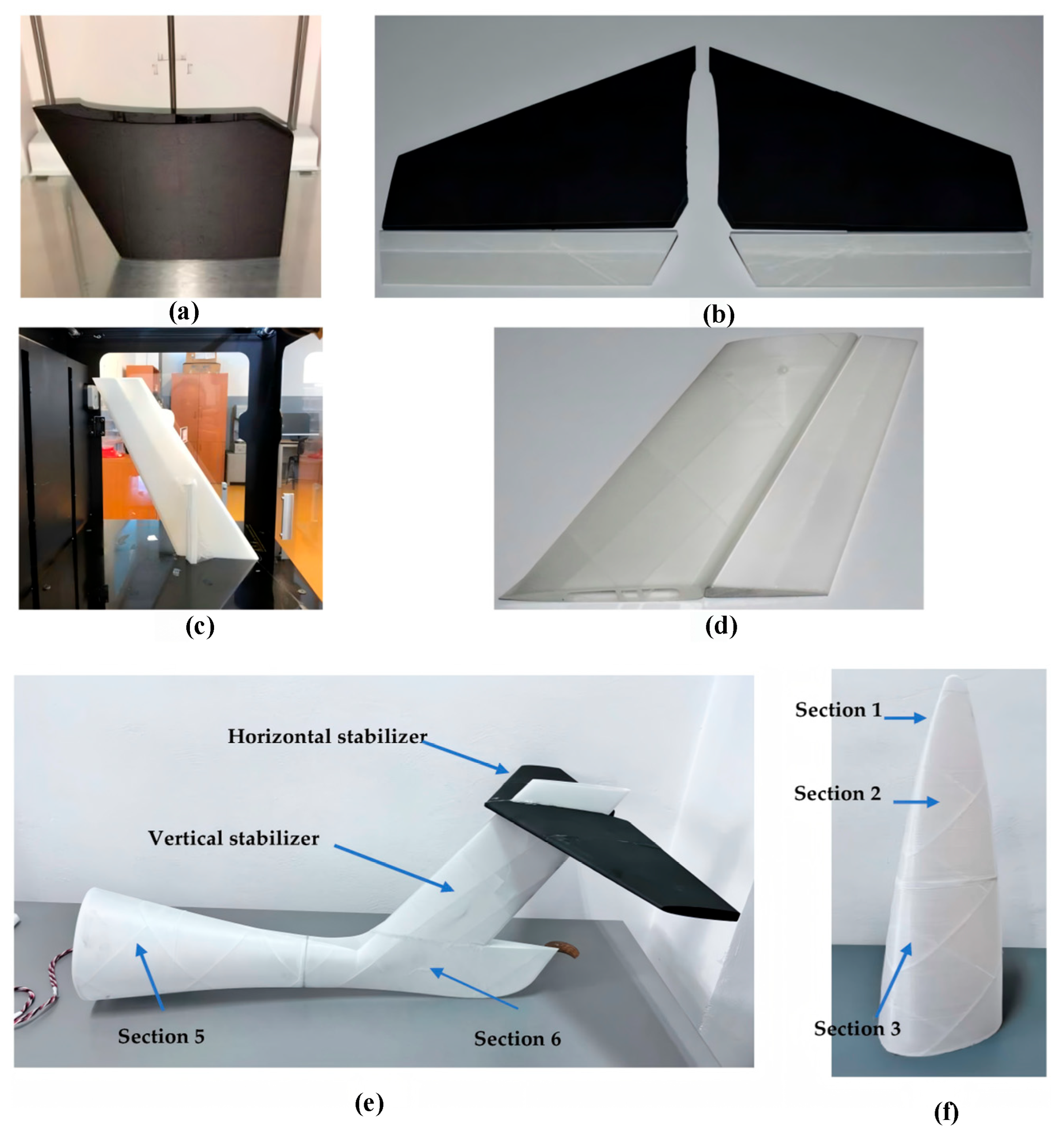
In specific applications, Zaharia [19] applied Material Extrusion AM technology to fabricate unmanned aerial vehicles, which presents high stability and maneuverability, a wide range of speeds, and good aerodynamic characteristics. An example can be seen in Figure 3 below. Huang et al. [20] proposed a multiscale topology optimization framework for lattice structures, in which the orientation of lattice cells is co-optimized with the macroscopic topology. For a benchmark Messerschmitt–Bölkow–Blohm (MBB) beam, the optimized structure achieved increases in the stiffness/peak load of 182.94%/57.96% compared to periodic lattices and 143.72%/20.71% compared to fixed lattices. This method was subsequently applied to a multirotor UAV, where experimental results showed that the UAV arm could withstand 10.42 times the operational load. A continuous carbon fiber reinforced polymer (CCFRP) lattice airframe consisting of only two printed components was fabricated, weighing 141.53 g and achieving a 54.61% weight reduction, thereby validating the feasibility of achieving high load-bearing capacity with lightweight design. In earlier work, Huang et al. [21] also employed continuous-fiber MEX to fabricate multi-wing spars and internal wing frameworks exceeding 1 m in length. The printed spar reached a maximum length of 1565 mm, and under vertical takeoff and landing conditions, it could withstand 32.16 times its own weight. Under aerodynamic loading at 40 m/s and an angle of attack of 4°, the maximum wing deflection was only 4.93 mm, demonstrating the engineering feasibility of replacing conventional spar–rib assemblies with MEX-fabricated structures. In terms of non-load-bearing and in-orbit applications, MEX has also been adopted for cabin components and small satellite structures. Kobenko et al. [22] used ULTEM 9085 to fabricate cabin class divider supports and folding seat tables via MEX, achieving a significant weight reduction compared to CNC-machined aluminum parts. Meanwhile, Rinaldi et al. [23] investigated the potential of PEEK for space applications, fabricating nanosatellite structures via MEX as a proof of concept for additive manufacturing in orbital environments.

1.1.4. Architecture Field

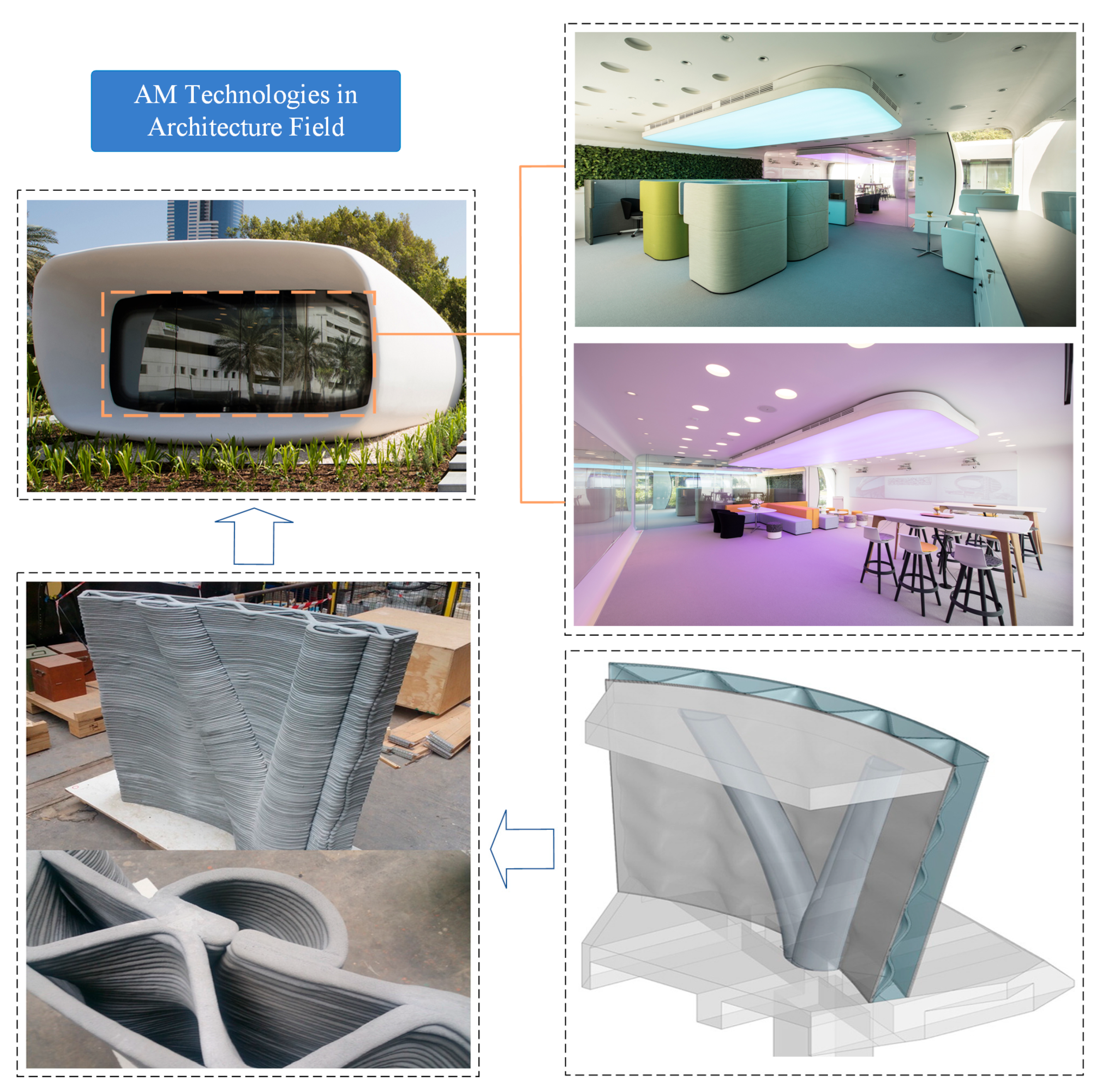
At present, additive manufacturing technologies can also be used in the construction sector by using cement-based materials [24]. During the construction by AM technologies, the layer-by-layer material deposition approach enables rapid building implementation while reducing resource consumption and waste generation significantly compared to traditional methods. Furthermore, AM concrete technology enhances design innovation freedom and construction productivity and enables architectural geometries unattainable through conventional techniques [25]. The Dubai Future Foundation has demonstrated the feasibility of additive manufacturing technology in large-scale construction through practical application. The building components were prefabricated by Chinese factories and transported to Dubai for on-site assembly. The building includes meeting room, fully functional office areas, and other spaces, as illustrated in Figure 4. Compared to the traditional construction technologies, AM technologies reduce labor requirements by 50% to 80% and construction waste by 30% to 60% throughout the entire process [26].

1.2. Additive Manufacturing Processes and Classification

AM technology, which represents a disruptive technology in the manufacturing sector, is composed of networked information, advanced materials, and digital manufacturing technology. The advantages of AM technologies include flexibility, precision, and the capability to fabricate complex geometries. It can significantly reduce time and cost [27]. According to the American Society for Testing and Materials (ASTM), AM technologies are classified into seven process categories: Vat Photopolymerization (VPP), Material Jetting (MJT), Binder Jetting (BJT), Material Extrusion (MEX), Powder Bed Fusion (PBF), Sheet Lamination (SHL), and Directed Energy Deposition (DED) [28]. It is summarized in Table 1 below.
Vat Photopolymerization refers to the process of curing and forming by irradiating a liquid photosensitive resin tank with ultraviolet light. Material Jetting refers to the process where a nozzle sprays liquid photosensitive resin or wax material onto the construction platform, allowing for immediate curing under ultraviolet light. Binder Jetting is the process where a nozzle sprays liquid binder into a powder bed to bond powder materials layer by layer and form a 3D entity. Material Extrusion refers to the process of a heated nozzle extruding thermoplastic materials and forming them layer by layer. Sheet Lamination refers to the process of stacking thin sheet materials layer by layer through bonding, ultrasonic welding, or cutting to form a shape. Powder Bed Fusion refers to the process of melting/sintering materials in a powder bed through a laser or electron beam and forming them layer by layer. Directed Energy Deposition refers to the process of melting synchronously conveyed metal powders or wires through high-energy beams and depositing them layer by layer [37].
The basic principle of AM is layer-by-layer material addition to form a 3D part, as opposed to subtractive manufacturing that fabricates by removing material. The common types of AM sub-categories include PBF-LB/P (Laser Beam, Polymers), PBF-LB/M (Laser Beam, Metals), Fused Filament Fabrication (FFF), Stereo Lithography Apparatus (SLA), Digital Light Processing (DLP), etc. They could use the methods of laser beams or thermal extrusion nozzles, etc., to enable the precise fusion or bonding of materials. Finally, they create the entity of various products [27].

1.3. Fused Filament Fabrication (FFF) Technology

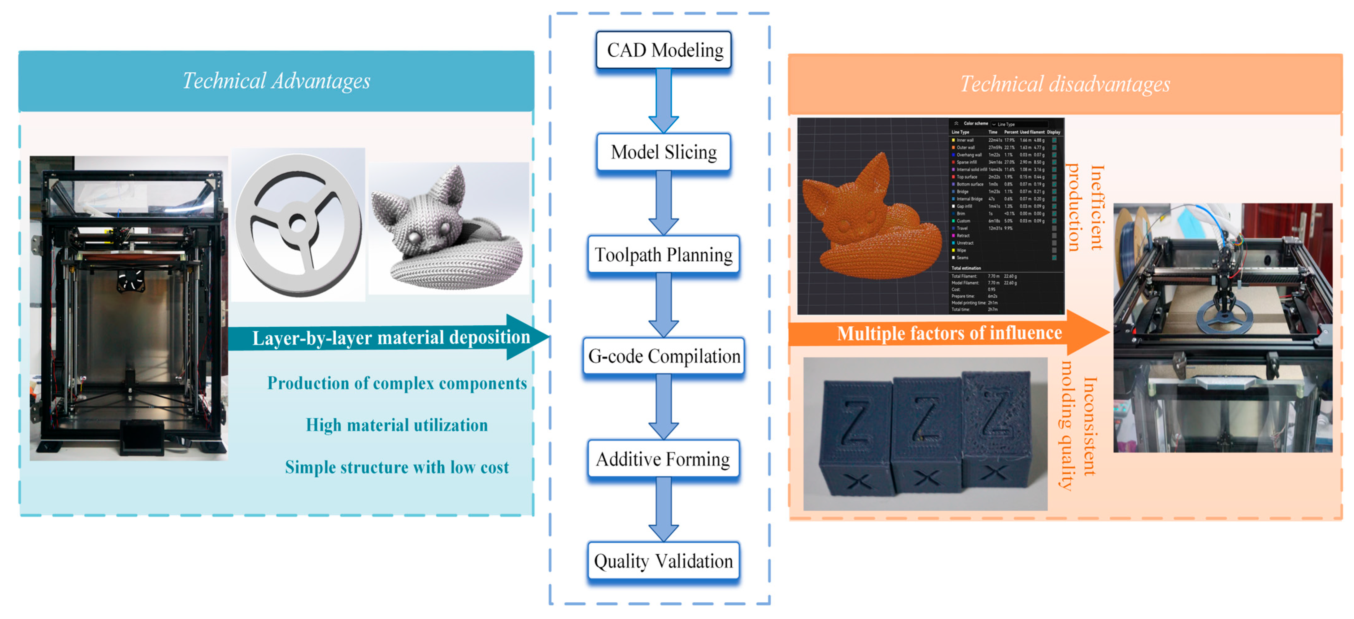
Fused Filament Fabrication (FFF) is one type of Material Extrusion process which forms objects by heating, extruding, and depositing thermoplastic materials layer-by-layer [38]. Currently, FFF technology has rapidly become the core process in both consumer-grade and industrial-grade markets due to its low cost, ease of operation, and broad material compatibility [39]. However, the manufacturing speed of FFF technology is a key barrier that prevents its widespread adoption. For example, one 5 cm3 component requires several hours to produce by a desktop-grade FFF printer, which indicates low production efficiency. The operation principle of FFF technology is shown in Figure 5 below.

2. High-Speed Material Extrusion Technology

2.1. Common Structure of ME Printer

FFF technology shows great potential in industrial manufacturing, medical customization, and creative design. For consumer-grade FFF equipment, speed is the key barrier preventing its widespread adoption. Currently, the mainstream structures of consumer-grade FFF equipment include gantry, box, and Delta structures. In addition, emerging structures such as polar coordinates have been optimized in specific application scenarios. These structures have significant differences in motion logic, component layout, and performance [40]. An example is shown in Figure 6 below.
Figure 6a: The gantry structure employs a rigid frame to support the X-axis (nozzle lateral motion) and Z-axis (nozzle vertical motion), while the Y-axis movement is realized through the forward and backward motion of the build platform. This configuration offers the advantages of structural simplicity and low cost, making it well-suited for desktop-scale applications. However, its primary limitation lies in the large moving mass of the Y-axis platform. Under high-speed or high-acceleration conditions, the significant changes in system momentum can induce vibration artifacts (ringing), material accumulation at corners, or even model displacement and layer misalignment when adhesion is insufficient. Overall, this architecture is more appropriate for educational use, proof-of-concept prototypes, and the medium-speed printing of small components. To achieve higher printing speed and quality, targeted enhancements should focus on reducing the heated bed mass, increasing frame rigidity, and implementing input shaping and mesh bed leveling.
Figure 6b: The polar-coordinate structure consists of a rotatable platform (θ-axis), a radial slide (ρ-axis), and Z-axis lifting motion [45]. This configuration offers distinct advantages when printing revolving or quasi-revolving geometries: during circular trajectories, motion primarily depends on platform rotation, which significantly reduces the stepped artifacts caused by the multi-segment polygonal approximation inherent to conventional Cartesian systems. It should be noted that, in polar coordinates, the linear velocity and resolution vary with the radius (since linear displacement is ΔS = R·Δθ). Therefore, path planning and acceleration/deceleration control must be radius-adaptive; otherwise, sudden speed variations and accuracy degradation may occur near the outer regions.
Figure 6c: The Delta structure employs three towers and three sets of parallel-link arms to drive the end effector within a three-dimensional workspace. Because the motors are fixed to the frame and the end effector is lightweight, this configuration offers high acceleration and high-speed potential, and the build height can be conveniently increased by extending the tower length. However, both kinematics and vibration behavior are configuration-dependent, making geometric calibration (including tower angles, arm lengths, and radii) and position-dependent vibration suppression particularly critical. In addition, due to the use of Bowden feeding systems—adopted to reduce the moving mass—precise pressure compensation and temperature control are required to maintain stable extrusion. Moreover, Delta variants with extended degrees of freedom can enhance the manufacturability of complex geometries, though they also impose greater demands on calibration and motion control accuracy. For example, Zhao et al. [46] expanded the freedom of Delta structure and demonstrated enhanced capability to fabricate complex components.
Figure 6d: In the enclosed “box-type” frame, the build platform moves solely along the Z-axis, while the X–Y motion is executed by the printhead. This configuration offers high spatial efficiency and facilitates temperature control, making it suitable for large-format printing. Among such systems, the Core X-Y architecture is the most common: two motors are fixed to the frame, and X–Y motion is achieved through crossed-belt coupling [47]. Fixing the motors significantly reduces the inertia of moving components, thereby increasing both the precision and the upper limit of achievable speed. However, the symmetry and tension of the belt paths, as well as the bending and torsional stiffness of the crossbeam, critically determine the performance limits of wide-format machines. Proper belt pre-tensioning, short and symmetric belt loops, and a crossbeam with a high moment of inertia are essential factors for achieving high-speed, high-quality printing.
The advantages, limitations, and trade-offs of the four structural architectures in the context of high-speed printing are summarized in Table 2. The gantry (bed-slinger) structure excels in simplicity and cost-effectiveness, but its high-mass moving bed constrains the upper limits of printing speed and surface quality. The polar-coordinate system offers unique benefits in printing revolving geometries, achieving high efficiency and smooth circular motion; however, it requires careful handling of radius-dependent variations in velocity and resolution. The Delta structure, featuring a lightweight end effector, enables high acceleration and is well-suited for speed-oriented prototyping and tall columnar parts, though it demands precise calibration and position-dependent vibration control. The Core XY enclosed (box-type) system provides the best overall balance, capable of high-speed and stable fabrication when supported by a rigid frame and a well-tuned belt system.
From an engineering perspective, the following can be stated:
(1)
For general purpose high-speed and high-quality printing, the Core XY box-type architecture is preferred.
(2)
For maximum acceleration performance, either Delta or Core XY designs are suitable.
(3)
For large-diameter rotational parts, the polar-coordinate system offers distinct advantages.
(4)
The gantry bed-slinger remains a cost-effective choice for educational use and small prototype fabrication.

2.2. Materials and Applications

2.2.1. Common Pure Resin Materials

During the Material Extrusion (MEX) printing process, material selection critically influences the quality of final printed components [48]. The fluidity and viscosity of different materials directly determine printing precision, particularly under high-speed conditions. Rational control of these parameters proves essential for enhancing both printing accuracy and process stability [49,50]. Material Extrusion (MEX) supports a diverse range of materials, each exhibiting distinct advantages and limitations, as summarized in Table 3.
Material Extrusion (MEX) additive manufacturing technology offered a varied applicability across different scenarios. Many engineering thermoplastics have been widely employed due to their exceptional mechanical strength, durability, and thermoplastic properties, such as Polylactic Acid (PLA) [63], Acrylonitrile Butadiene Styrene (ABS) [64], Polyethylene Terephthalate Glycol (PETG) [65], etc. These materials eliminate specialized light-shielding storage requirements and demonstrate superior environmental adaptability in industrial applications [51]. Polylactic Acid (PLA) stands as one of the most widely used printing materials. Derived from corn fermentation, it offers low cost, non-toxicity, and excellent biodegradability, making it suitable for medical implants and educational applications [49]. During printing, PLA typically requires a nozzle temperature of approximately 200 °C, producing components with minimal warping and high rigidity. However, PLA exhibits a limited mechanical performance and poor heat resistance and is prone to softening and deformation under elevated temperatures [50].
Acrylonitrile Butadiene Styrene (ABS) is another prevalent material valued for its high-temperature resistance and superior strength [63]. But its high melting temperature and significant shrinkage necessitate the use of a heated bed and enclosed build chamber to prevent warping and cracking defects [64]. As a petroleum-derived material, ABS emits pungent fumes during printing, requiring ventilation. Although these are processing challenges, its exceptional mechanical properties ensure broad industrial applicability. As an amorphous copolyester material, Polyethylene Terephthalate Glycol (PETG) demonstrates an outstanding comprehensive performance in additive manufacturing. It combines high toughness, transparency, and low shrinkage, rendering it highly compatible with FFF technology [65]. Flores et al. [48] revealed that PETG retains favorable mechanical properties even after five extrusion–recycling cycles, with tensile strength nearing commercial filament levels after three cycles. PETG finds extensive applications in food-grade packaging, industrial protective equipment, and enclosures for consumer electronics, emerging as an ideal choice for balancing functionality and aesthetics.
High-performance polymers—with their higher glass transition temperatures, thermal stability, and chemical resistance—enable the use of MEX in harsher environments. For instance, PEI Polyether Ether Ketone (PEEK) exhibits excellent strength, chemical stability, and wear resistance, maintaining mechanical integrity under demanding conditions. High-performance polymers, with their high glass transition temperatures, thermal stability, and chemical resistance, enable applications in demanding environments. For example, the ULTEM series of polymers are amorphous polyetherimide (PEI)–polycarbonate (PC) thermoplastic blends that have attracted wide attention due to their excellent flame retardancy [66]. Among them, ULTEM 9085 stands out as one of the most prominent materials. It is a relatively new polymer commonly used in Material Extrusion (MEX) printing technologies and is the first 3D printing thermoplastic to be certified by the Federal Aviation Administration (FAA) for use in aerospace applications [67]. Another important family of high-performance thermoplastics is PAEK (polyaryletherketone), which includes PEEK (Polyether Ether Ketone) and PEKK (polyether ketone ketone). These materials exhibit outstanding chemical and thermal resistance along with high mechanical strength [68]. When processed via Fused Filament Fabrication (FFF), PAEK polymers are widely applied in aerospace, medical, and other high-performance engineering fields [69].

2.2.2. High-Performance Composite Materials

Given the diverse application scenarios of Material Extrusion (MEX), researchers have developed a wide range of high-performance materials. Carbon fiber-reinforced polymers (CFRPs)—comprising carbon fibers as reinforcement and a polymeric resin matrix—combine lightweight and high-strength characteristics, making them widely applicable in aerospace, automotive, and hydrogen storage cylinder reinforcement [70]. In additive manufacturing, CFRPs are typically classified according to fiber continuity into continuous and discontinuous fiber-reinforced systems. For discontinuous CFRP composites, additive manufacturing is well-supported by existing slicing software capable of fabricating complex geometries while maintaining printability, offering measurable performance gains. However, the degree of reinforcement depends strongly on fiber orientation and integrity. Vatandas et al. [71] demonstrated that printing short carbon fiber-reinforced PEEK under vacuum conditions significantly reduced porosity and improved part density, resulting in a 79.75% increase in flexural strength. Compared with continuous fiber systems, short-fiber composites are more prone to fiber deformation, breakage, and orientation loss within the nozzle, leading to lower-than-expected reinforcement efficiency. To address these challenges, Guo et al. [72] developed a coupled Computational Fluid Dynamics–Discrete Element Method (CFD–DEM) model to characterize the multiphase interactions between non-Newtonian fluids and flexible fibers during MEX. By increasing nozzle raster height and optimizing feed angles, they achieved more uniform fiber alignment while mitigating fiber deformation and breakage.
For a given matrix, continuous carbon fibers deliver a substantially higher mechanical performance than pure resins. Using PLA as an example, Zhang et al. [73] compared different winding strategies for long fibers and found that the fiber deposition direction had a major influence on mechanical behavior. The optimized configuration achieved 192% higher tensile strength and 198% higher flexural strength relative to conventional resin specimens, indicating significant improvements in stiffness and strength. Liu et al. [74] further proposed an explicit streamline tracking method that converts the stress field into adaptive toolpaths for continuous fiber-reinforced polymer composite additive manufacturing. By using the principal stress direction and magnitude to control toolpath density and distribution, this approach improved stiffness and strength by 200–300% compared with traditional uniform toolpaths.
Additionally, to achieve specialized functionalities such as thermal conductivity or corrosion resistance, researchers have developed metal–ceramic composite materials for MEX-based fabrication. After debinding and sintering, these components yield dense structures with customized properties unattainable in pure materials, thereby expanding the design flexibility of additive manufacturing [75]. For instance, Rubiano Buitrago et al. [76] investigated the filament-based printing of WC–10Co cemented carbide powders, designing a polypropylene grafted with maleic anhydride (PP-MA) binder system. Results showed that increasing the PP-MA proportion enhanced the interfacial bonding between powder and polymer, leading to denser layer adhesion and a significant reduction in porosity and cracking. Furthermore, the material flow rate was identified as a critical parameter influencing both the printing quality and speed. Yi et al. [77] compared NiFe2O4–25(Cu–20Ni) metal–ceramic feedstocks prepared with varying solid contents in a polyformaldehyde (POM) binder system and found that a lower solid content resulted in fewer interlayer voids and higher part density. Thus, improving the feedstock flow behavior is critical to achieving both part quality and process efficiency in metal–ceramic material extrusion (MEX) additive manufacturing.

2.2.3. Optimized High-Speed Materials

In the commonly used PLA, ABS, and PETG systems, researchers generally adopt strategies such as adding flow modifiers, nucleating agents, and compatibilizers to improve the shear flow behavior of the melt without significantly compromising mechanical performance. For example, in the case of PLA, the printing parameters recommended by various manufacturers for high-speed PLA materials are summarized in Table 4. These modified polymer blends maintain low viscosity and stable melt flow under high shear rates. By promoting segmental diffusion and synchronizing crystallization kinetics, they achieve faster solidification rates and stronger interlayer adhesion. Such high-flow formulations can reduce the total printing time by approximately 60–70% compared with conventional materials by lowering melt viscosity and optimizing thermal management. However, the precise control of thermal stress and warping behavior remains critical at high flow rates to maintain geometric accuracy [78]. Kruzliak et al. conducted comparative experiments showing that, for rheologically modified HS-PLA, the tensile strength decay rate between 50 and 300 mm/s at 230 °C was only half that of conventional PLA. This result further demonstrates that synergistic formulation design and temperature control can effectively expand the high-speed printing [79].
For composite materials—particularly particle-filled MEX feedstocks—adjusting the fiber or metal–ceramic content can enhance flow performance during printing. For instance, increasing the metal filler content raises viscosity, while waxes in the binder system help reduce viscosity and improve flowability [80].
Table 4. Printing parameters of representative high-speed PLA materials.
MaterialManufacturerRecommended Nozzle Temperature (°C)Recommended Speed (mm/s)Volumetric Flow Rate
PolySonic PLA [81]PolymakerHigh-speed: 210–230; Regular: 190–210High-speed: 100–300; Regular: 50–100-
Ultrafuse PLA PRO1 [82]BASF Forward AM200–22040–30022 mm3/s
PLA Basic [83]Bambu Lab190–230250–300-
Hyper Speed PLA [84]Raise3D200–23060-300-
ePLA-HS [85]eSUN190–23050–350-

3. Technical Challenges in High-Speed ME Technology

In Material Extrusion (ME) additive manufacturing, achieving high-speed printing is not simply a matter of increasing the motion speed. Rather, it requires a balance between the motion system and the volumetric flow rate of the hot end. Fundamentally, the process must ensure synchronization among three temporal domains—heat supply and melting, mechanical motion response, and cooling and interlayer adhesion—so that stable deposition and reliable part formation can be maintained, even at elevated speeds.
This chapter focuses on three major bottlenecks commonly encountered during high-speed operation:
(1)
Insufficient material flow, caused by limited hot-end throughput and inadequate melt residence time;
(2)
Vibration issues arising from the platform, extrusion system, and motion transmission under high acceleration and deceleration;
(3)
Thermal management imbalance, resulting from inefficient cooling and temperature control of the build environment.
Moreover, we emphasize that different application requirements—particularly regarding part strength and dimensional accuracy—can significantly alter the practical printing speed window. For instance, parts with identical geometries but different infill densities often exhibit drastically different printing times and mechanical properties. Therefore, this work further explores the coupled effects of infill density and infill pattern (toolpath design) on both printing speed and mechanical performance, aiming to develop a high-efficiency process framework that balances speed and quality.

3.1. Melt Flow Issues

As the movement printing speed increases, the printer’s hot end often experiences insufficient flow supply. The hot-end flow rate, defined as the volume of molten plastic passing through the nozzle per unit time, serves as one of the core control parameters in printing. Its significance is manifested not only in directly influencing print quality aspects such as mechanical strength and surface roughness, but also in constraining printing efficiency [38].
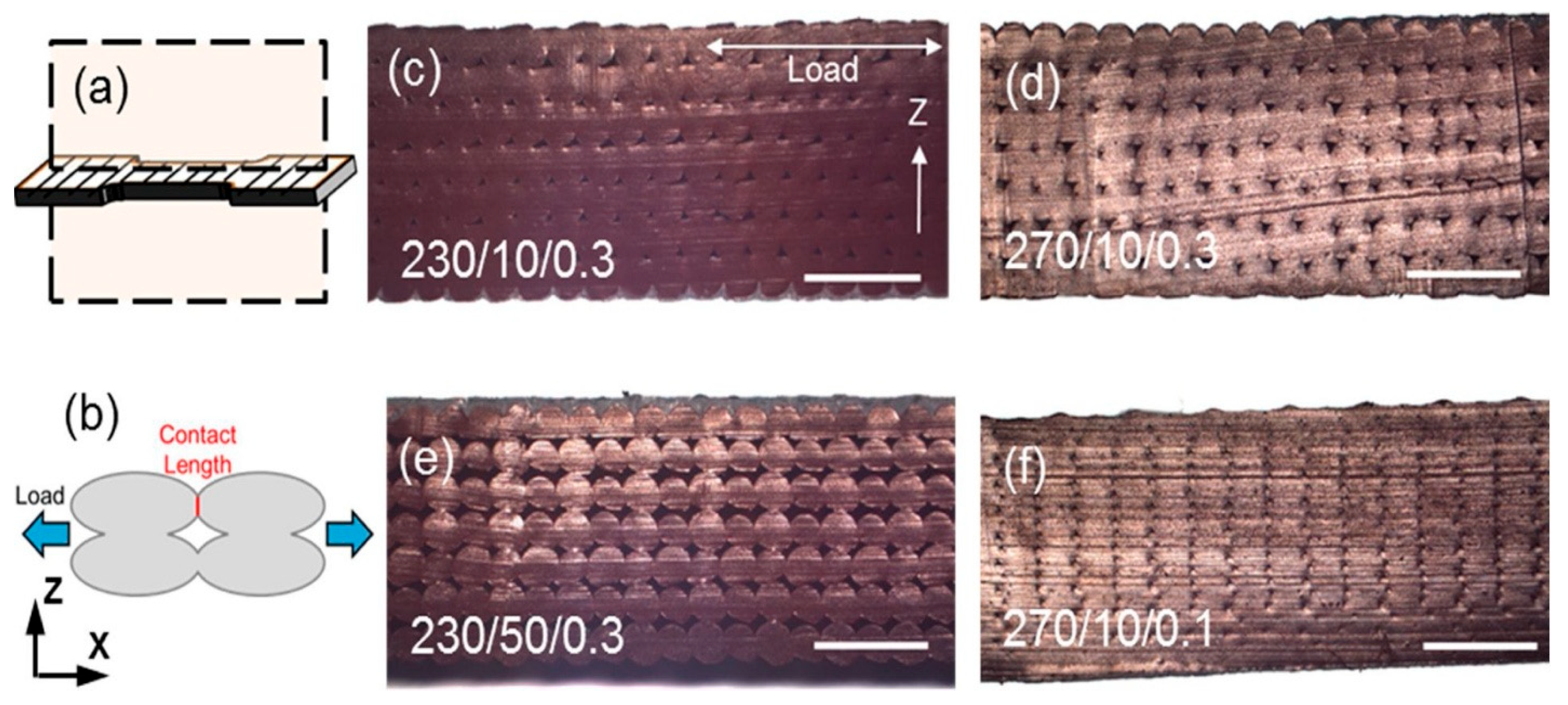
Jamison Go et al. [86] discovered that under identical resolution conditions, the printing speed is affected by factors including movement speed, length of the hot-end liquefaction channel, and hot-end temperature. Fundamentally, this reflects the balance between the material flow rate and hot-end movement speed. When the flow rate remains constant but the hot-end movement speed increases, the molten material cannot fully fill the deposition path, thereby compromising overall part quality. Abbott et al. [87] evaluated the effects of parameters such as hot-end temperature and print speed on ABS material prints, finding that, at a fixed temperature and layer height, an increased print speed leads to an increase in porosity and a decrease in print quality of the printed parts, as shown in Figure 7. Conversely, an excessive flow rate may cause material over-accumulation or irregular overflow, forming hardened particles on the part surface that degrade dimensional accuracy. During high-speed printing, the predominant issue tends to be insufficient material flow, making the enhancement of material flow rate a critical challenge for achieving high-speed printing.

3.2. Thermal End and Ambient Temperature Control Issues During High-Speed Printing

In Material Extrusion (ME) Additive Manufacturing, increasing the printing speed requires not only sufficient material flow capability but also effective thermal management of the system, which primarily includes hot-end temperature control and build-environment temperature regulation.
An elevated hot-end temperature reduces the melt viscosity and yield stress, thereby lowering the pressure drop and enabling a higher melt flow rate under the same driving force. However, excessive temperature may lead to melt sagging, so the material temperature must be maintained at an optimal point that allows speed enhancement without compromising strength [88,89]. Moreover, the temperature uniformity and response rate of the hot end directly influence the attainable printing speed. Since MEX materials are predominantly polymers, sometimes modified with conductive additives such as carbon black or metal powders, their thermal conductivity from the hot-end wall to the polymer melt remains relatively poor. To ensure sufficient melting, the residence time of the polymer in the melt zone is therefore increased to promote uniform heat distribution [90].
Environmental temperature regulation determines the thermal trajectory of deposited layers during the deposition and cooling phases. Increasing the chamber temperature or reducing forced-air cooling raises the interfacial temperature and extends the diffusion time, thereby mitigating warping and delamination while maintaining adequate interlayer bonding even at higher speeds. The study by Gong et al. [91] demonstrated a strong coupling between ambient temperature and printing speed: raising the chamber temperature significantly improved interlayer adhesion at speeds of 70–90 mm/s, with ambient temperature contributing the largest effect among multiple influencing factors.
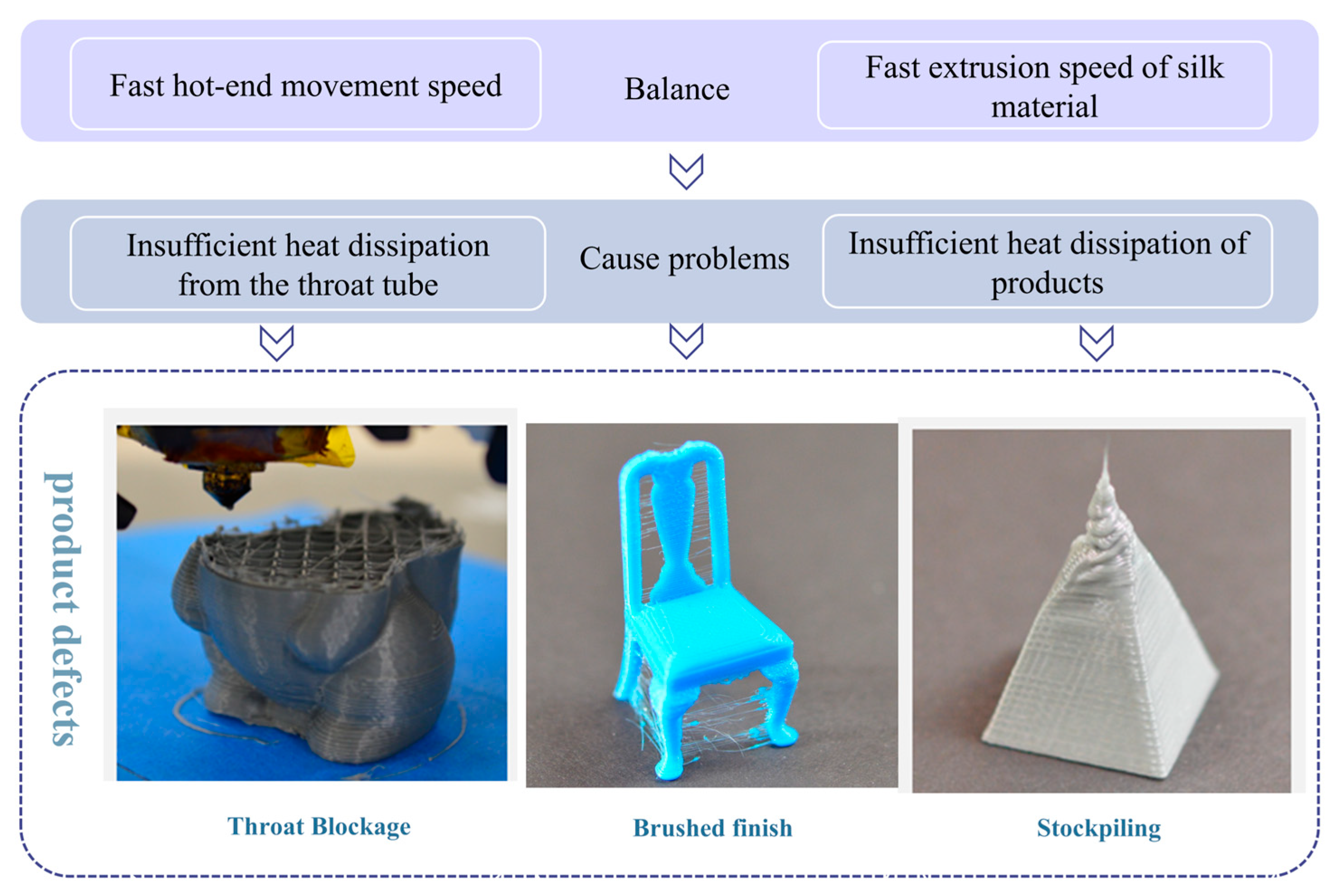
Typical problems arising from imbalanced thermal management, as illustrated in Figure 8, can be categorized into three types:
(1)
Overheating of the heat break region—insufficient heat dissipation causes premature softening and wall adhesion of the filament, eventually leading to nozzle clogging;
(2)
Inadequate cooling of printed parts—slow melt solidification may result in stringing during non-print moves or material accumulation on small-area features such as pyramid tips;
(3)
Uneven hot-end temperature under excessive feed rates, which produces unstable extrusion flow.
A fast-response hot-end temperature control system, coupled with optimized chamber thermal management—balancing material cooling and part insulation or localized heating—can effectively extend the upper speed limit while preventing strength degradation and surface defects caused by an insufficient thermal history.

3.3. Vibration Issues During High-Speed Printing

In Fused Filament Fabrication (FFF), vibrations generated within the printer primarily stem from the dynamic interactions of mechanical components, including the rapid translational motion of the print head, pulsed excitation from stepper motors, and structural resonance within the printer frame. During high-speed operations, inertial forces during acceleration and deceleration phases exacerbate vibrations, leading to print head jitter and interlayer misalignment. When the driving frequency of moving components, such as the print head or heated bed, approaches the system’s natural frequency, structural resonance occurs, significantly amplifying vibrations [92]. This resonance not only reduces printing accuracy and causes surface rippling (wave-like texture) but also risks structural damage to the printer due to mechanical overload.
Beyond vibrations generated by the printer itself, printed parts are also susceptible to external environmental vibrations. Jensen et al. [93] found that vibrations from the printer’s external base are a primary source of print quality degradation, as shown in Figure 9. Simple passive vibration damping can improve part surface quality by 16%.

3.4. Interlayer Resolution and Mechanical Strength in Speed Limitation Issues

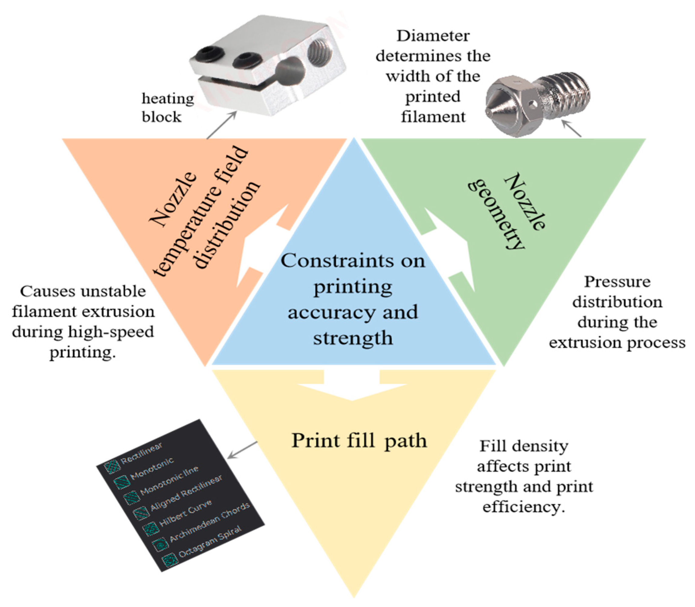
In the Material Extrusion (MEX) printing process, printing accuracy and mechanical strength impose inherent constraints on the achievable printing speed. Both factors are influenced by the temperature field distribution [94], nozzle fluid dynamics [95], and printing process parameters [96], which collectively limit the upper bounds of speed, as illustrated in Figure 10.
The nozzle diameter directly determines the interlayer resolution and minimum printable feature size. A smaller diameter yields higher resolution and finer surface finish but limits the volumetric flow rate of the hot end. Conversely, a larger diameter increases material throughput, allowing for greater layer height and faster movement speeds but at the cost of geometric detail and surface quality [97].
Regarding part strength, achieving a desired mechanical performance in MEX printing typically involves increasing the infill density or selecting mechanically superior infill patterns/toolpaths (e.g., Honeycomb or Gyroid structures). However, these strategies inherently increase the extrusion volume per unit part volume and extend toolpath length, thereby prolonging the printing time and reducing the effective production speed. Recent optimization studies have therefore aimed to minimize printing time while maintaining acceptable strength, showing a quantitative trade-off: as the infill density increases, printing time rises significantly; yet, by appropriately scaling or constraining the density, the printing duration can be shortened with only a minor reduction in mechanical strength [98].

4. Optimization Method of High-Speed ME Technology

4.1. High-Speed Traffic Boosting and Control

To solve the problem of an insufficient flow rate for high-speed printing, researchers typically employ higher feed rates to increase hot-end flow. However, excessively high filament feed speeds may cause overflow of molten material in the hot end, potentially clogging the print head [99]. Therefore, improving system throughput must be based on the precise analysis of the thermodynamic behavior and rheological characteristics within the hot end.
Zhang et al. [100] conducted a temperature field analysis covering the entire process from filament feeding to part cooling, indicating that the printing material mainly exists in a molten state within the nozzle system. If the temperature is too low, the rheological properties of the polymer will be significantly reduced, hindering the extrusion process. Their study demonstrated that higher nozzle temperatures during feeding help pressure transmission, thereby achieving higher maximum volumetric flow rates. Serdeczny et al. [101] proved that during high-speed printing, excessive feeding speed reduces the residence time of the material in the flow channel, preventing it from reaching the target temperature and causing a nonlinear increase in driving pressure. Under these conditions, if the filament lacks sufficient mechanical strength, the extrusion gear may impose excessive shear or grinding on it, eventually leading to printing failure. Therefore, the rational matching between hot-end temperature control and feeding speed is a key factor to ensure adequate melting and stable flow of the material, which plays a decisive role in achieving high-speed and high-quality printing.
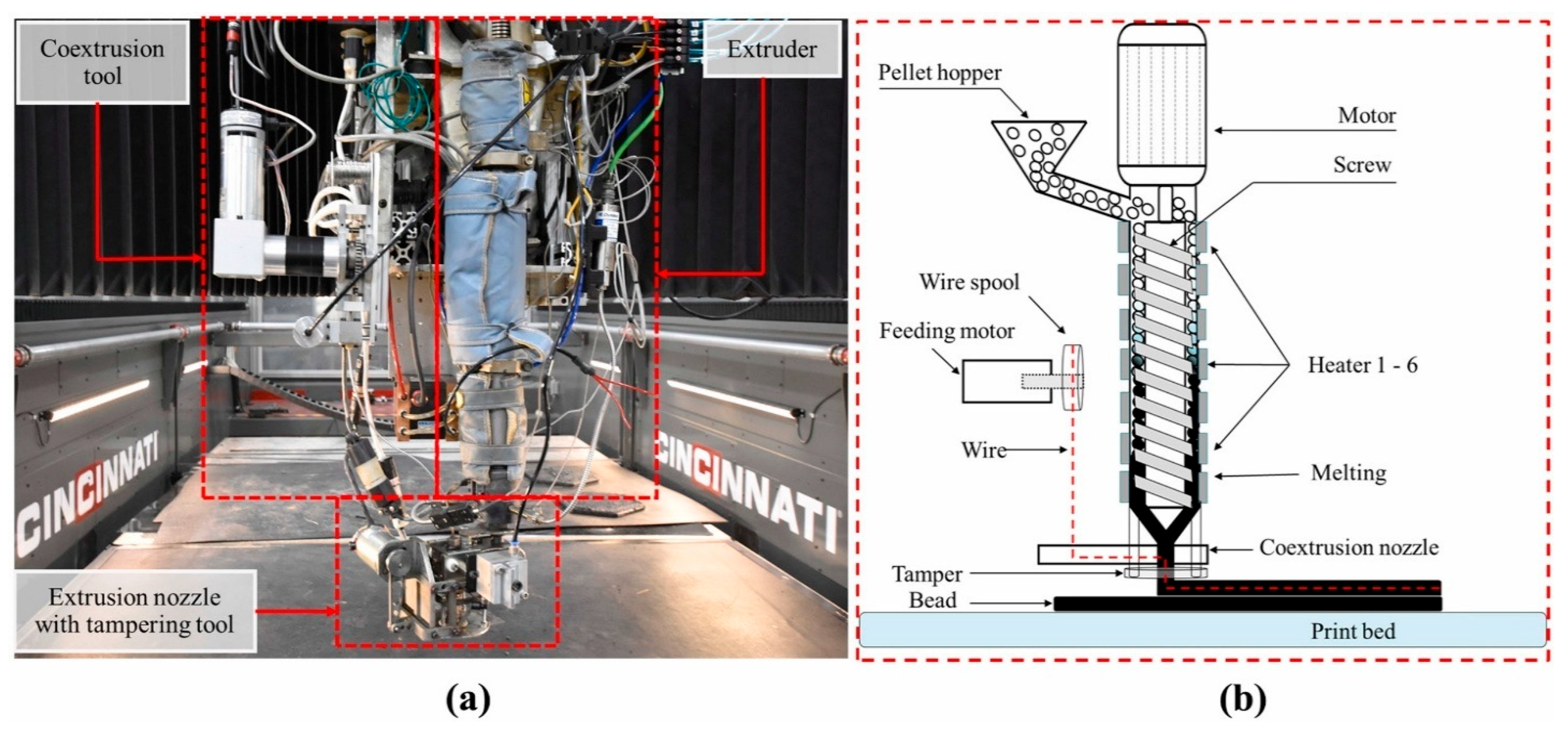
In addition, the feeding method has a significant influence on the hot-end flow rate and printing performance. Traditional FFF systems use thermoplastic filaments as the feedstock, and different drive structures directly affect the extrusion rate of the nozzle. The Big Area Additive Manufacturing (BAAM) system developed by the Oak Ridge National Laboratory (ORNL) replaces the filament with pelletized engineering plastics and adopts a screw extrusion structure, which significantly increases the extrusion speed and shortens the printing time [102]. Billah et al. [103] proposed a method for fabricating self-heating composite molds by combining large-scale pellet extrusion additive manufacturing (BAAM) with a resistance-wire co-extrusion process, as illustrated in Figure 11. In this approach, heating wires are embedded into the mold during the printing process, enabling internal heating and precise temperature control. This technique significantly reduces mold fabrication cost and production time, while demonstrating the feasibility and thermal uniformity of the method for composite molding applications. Liu et al. [104] designed a novel large-scale printer with a two-stage screw structure: the first screw melts and pressurizes the plastic pellets, while the second metering screw precisely controls the melt flow rate, enabling high-speed and low-cost manufacturing. The study also analyzed the relationships among the hot-end flow rate, pressure, and screw speed, revealing that the proper matching of printing speed and melt flow rate is critical to ensuring high-speed printing quality. Woern et al. [105] compared recycled pellet materials and found that pellet-feeding systems achieve printing speeds 6.5–13 times faster than conventional filament feeding, offering higher material recyclability and a lower cost. However, the BAAM process is not stable; during large-scale fabrication, temperature non-uniformity occurs. Caltanissetta et al. [106] used an infrared thermal imager to monitor temperature variations during BAAM printing, and the results showed that there was a temperature difference between the outer and inner layers.
In summary, filament feeding technology offers high dimensional control precision. By enhancing the rheological properties of materials in hot-end channels, it increases printing speed, gaining an advantage in small-to-medium-sized and high-precision applications. In contrast, pellet-feeding technology, with its extremely high extrusion rate and material utilization, is more suitable for the rapid fabrication of large structural components and industrial-scale mass production. The synergistic development of these two technological paths provides an important approach to overcoming the limitations of hot-end flow and the bottleneck of printing efficiency.

4.2. Thermal Management Optimization Requirements and Strategies

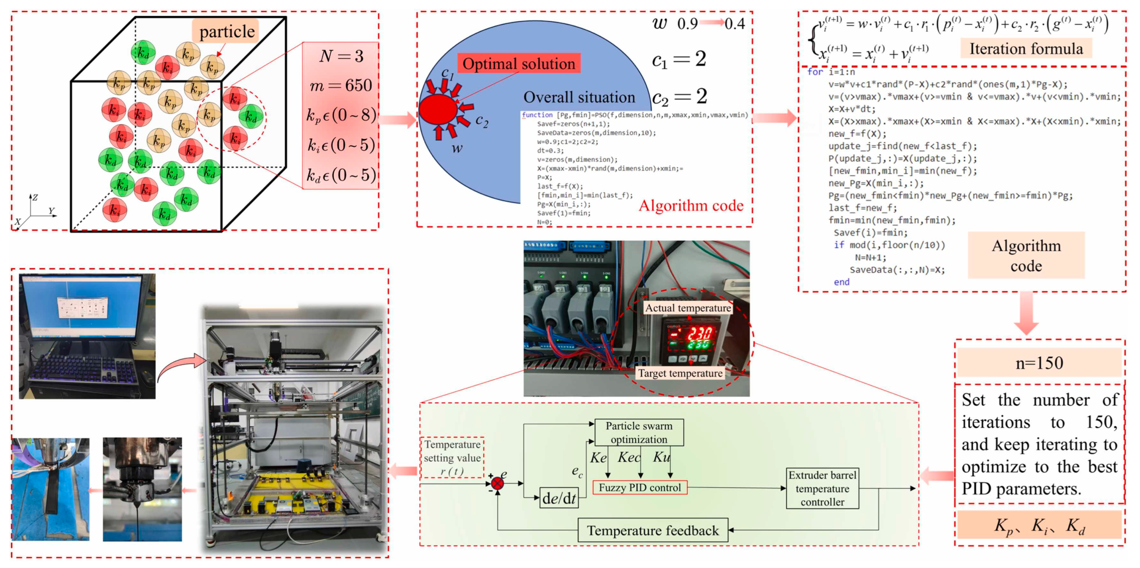
As the printing speed increases, the residence time of the material within the hot end decreases. To ensure sufficient material flow during high-speed printing, it is essential to maintain precise and uniform hot-end temperature control with fast thermal response, ensuring complete material melting. To address this, Long et al. [107] investigated a PID-based temperature control system for Fused Filament Fabrication (FFF) 3D printers. By introducing a PID control algorithm, they significantly improved the temperature regulation accuracy of the hot end. Huo et al. [94] proposed a dual-temperature heating control method to replace the conventional single-temperature control. This approach achieved a more uniform temperature distribution within the material, enhanced the printing resolution to 50 μm, and increased the critical printing speed for forming continuous and stable filaments compared to standard single-point temperature control. For pellet-based additive manufacturing, Zavrakli et al. [90] developed a linear quadratic tracking (LQT) framework to address temperature control challenges in Big Area Additive Manufacturing (BAAM) systems. Simulation results verified the effectiveness and stability of this control strategy in improving the thermal performance under dynamic printing conditions. Liu et al. [108] proposed a fuzzy PID control approach optimized by particle swarm optimization, effectively addressing issues such as sluggish response, significant fluctuations, and weak anti-interference capabilities in the temperature control system of extrusion devices, as illustrated in Figure 12. Experimental results demonstrate that this method outperforms traditional PID and fuzzy PID controls in terms of temperature response speed, mechanical properties of printed parts, and surface quality.
It is worth noting that increasing the hot-end temperature alone to improve the printing speed—while neglecting the control of the build environment temperature—will inevitably lead to defects such as material accumulation and over-deposition. The optimal thermal environment also varies depending on the material type. For materials such as ABS and PEEK, which are highly sensitive to interlayer temperature, elevating the chamber temperature or reducing forced air cooling can significantly lower thermal gradients and residual stresses, thereby suppressing warping and allowing the printed parts to maintain strong interlayer bonding and dimensional stability even at higher printing speeds. Samy et al. [109] demonstrated that, when printing with polypropylene, increasing the nozzle speed from 30 mm/s to 60 mm/s reduced the residual stress in the bottom and top layers by 15% and 13%, respectively. This improvement was attributed to enhanced thermal transfer during deposition and a slower cooling rate. Similarly, Doyle et al. [69] investigated the effects of nozzle temperature, bed temperature, chamber temperature, and printing speed on the quality of PEEK printed parts, finding that both bed and chamber temperatures had a significant impact on part density. Raising the chamber temperature helped maintain an adequate interfacial temperature and diffusion time at higher printing speeds. In related research, Choi et al. [110] conducted ABS printing experiments under varying build-plate temperatures. The results showed that increasing the bed temperature reduced thermal shrinkage deformation, and at an extrusion temperature of 110 °C, interlayer adhesion was notably improved. To address this, Santos et al. [111] developed a segmented heated bed system (200 × 200 mm PCB substrate) comprising 16 independently controlled resistive heating units. By homogenizing the temperature distribution between the center and edges of the bed and enabling targeted heating of specific areas, this design significantly reduced energy consumption and thermal gradients.
During the filament feeding process in FFF, as the temperature rises, the material transitions from a glassy state to a rubbery state, and eventually to a molten state [112]. Under high-speed printing conditions, elevated chamber and hot-end temperatures may cause premature softening of the filament, leading to insufficient extrusion force in FFF systems. To optimize heat dissipation in the heat break and mitigate filament grinding and feeding issues, Yi et al. [113] designed a novel nozzle structure. The cooling component in the throat employs high-temperature thermal oil as the heat transfer medium, while the cooling tube, constructed based on the magnetocaloric principle, is designed as an immersed serpentine tube with two closed-loop fluid exchange channels. This configuration effectively mitigates clogging issues while enhancing the surface quality of printed models.
In summary, ensuring the quality of additive manufacturing relies on a robust temperature control system. Precise regulation of nozzle temperature maintains extrusion stability, optimization of the printing environment temperature minimizes residual stress and deformation, and the implementation of an efficient hot-end nozzle cooling mechanism prevents blockages and thermal expansion defects. Collectively, these measures achieve comprehensive improvements in print accuracy, structural stability, and functional performance.

4.3. Vibration Effects and Control Strategies

During the manufacturing process, internal system vibrations are an inherent and unavoidable phenomenon in printer motion, primarily stemming from the dynamic response characteristics of components such as the print bed, extruder, and drive system. Vibration significantly affects the surface quality of printed parts. Although surface roughness is primarily determined by layer thickness, vibration, as a key factor, can disrupt the stability of the layer-by-layer deposition process, resulting in uneven surface texture and potential dimensional errors [114].
Chan et al. [115] analyzed the Prusa i3 MK3S+ printer through modal analysis and experimental testing, and the deviation between the experimental and simulation results was less than 13%. They also found that achieving high-speed and high-precision printing requires understanding and quantifying structural vibration modes, natural frequencies, and dynamic response characteristics. In multicolor printing, Zhang et al. [116] demonstrated that the vibration characteristics of FFF color 3D printers have a significant impact on printing accuracy. In color printing, the presence of color boundaries amplifies vibration effects, which may cause color layer displacement or blurring. Through modal analysis, they optimized the printer’s structural design to improve the vibration characteristics of the system, thereby significantly enhancing printing accuracy and the clarity of color layers, as shown in Figure 13. Edoimioya et al. [117] proposed a vibration compensation method based on a feedforward control FBS algorithm to address the resonance problem in high-speed Delta printers, which significantly improved print quality. Kopets et al. [118] proposed a natural frequency estimation method for Cartesian printers, which can be used at the design stage to predict the printer’s vibration characteristics and avoid resonance risks.
However, vibration is not entirely detrimental. Alhadar et al. [119] reveal that appropriately controlled mechanical vibration can effectively reduce porosity defects in FFF printed parts, thereby significantly improving the tensile strength, flexural strength, and surface quality of Polylactic Acid (PLA) materials. Nevertheless, they emphasize that vibration parameters must be precisely optimized based on material properties, equipment configuration, and print structure. Excessive vibration frequency or amplitude may lead to interlayer misalignment, reduced dimensional accuracy, or aggravated surface defects. Additionally, Mishra et al. [120] developed an artificial neural network model based on vibration signals to identify the operational state of 3D printers, achieving a prediction accuracy of 92%. By real-time monitoring of vibration data, this model can promptly detect anomalies during the printing process, such as nozzle clogging or uneven material deposition, providing a basis for adjusting print parameters and significantly improving print quality and production efficiency.
In conclusion, excessive vibration significantly degrades the surface quality of printed parts, and the manufacturing process is complexly influenced by factors such as printer structure, nozzle type, material properties, and infill structure. Consequently, the design of 3D printing systems should prioritize vibration control through optimized structural design and the integration of intelligent monitoring technologies to achieve superior surface quality and print accuracy, thereby meeting the demands of complex manufacturing applications.

4.4. Interlayer Resolution and Mechanical Properties Under High-Speed Conditions

During the printing and fabrication of parts, the accuracy of printed components is directly related to the geometry of the nozzle. The extrusion nozzle determines the shape and size of the extruded filament, and the minimum printable feature size cannot be smaller than the nozzle diameter [121]. Moreover, variations in nozzle geometry not only affect the dimensional accuracy of printed parts but also directly influence the flow behavior and pressure distribution of the molten polymer during extrusion—meaning that the nozzle plays a critical role in determining achievable printing speed [122]. Inside the nozzle, the molten material behaves as a viscoelastic fluid, whose flow characteristics are governed by tensile and shear deformation conditions as well as temperature distribution along the flow channel. To address the trade-off between printing precision and flow rate, two main strategies have been developed:
(1)
Optimizing nozzle geometry to reduce the total pressure drop and mitigate backflow effects while keeping the nozzle diameter constant;
(2)
Using variable-diameter nozzles, which enable rapid deposition with a larger orifice, followed by fine surface finishing using a smaller one, thereby achieving high surface quality and productivity without significantly increasing the total print time.
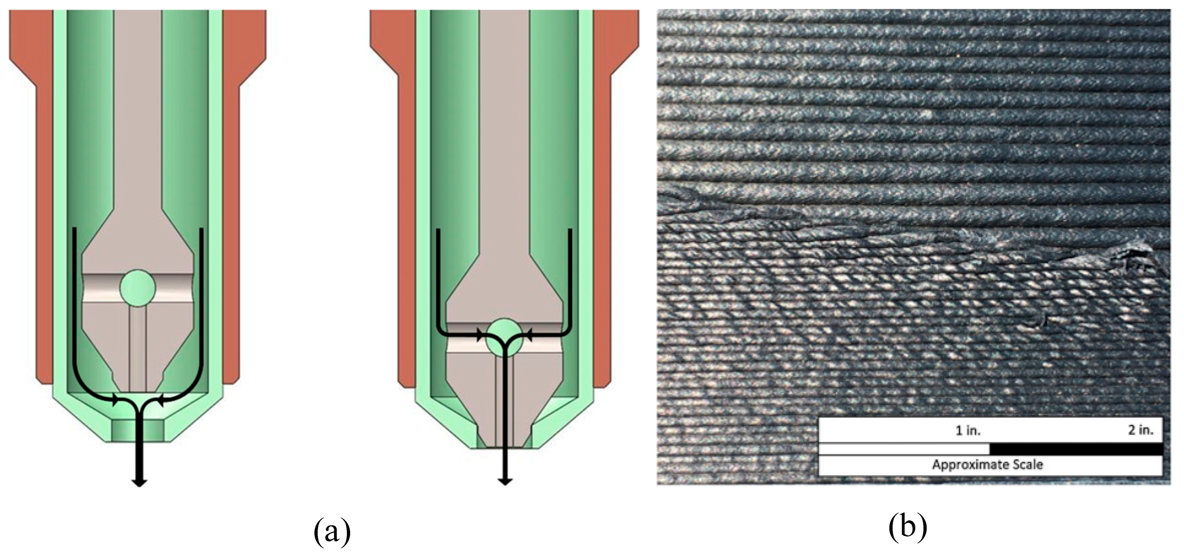
Sietse de Vries et al. [123] developed a novel pressure-sensing nozzle capable of monitoring the internal pressure distribution. Their results showed that melt backflow has a pronounced impact on the pressure drop, and minimizing this drop is essential for stable high-speed extrusion. Excessive pressure drop during high-speed printing can cause extrusion fluctuations, leading to an inconsistent filament diameter and reduced printing accuracy. Tomas Schüller’s team [124], combining computational fluid dynamics (CFDs) simulations with a global optimization algorithm, designed a convergent nozzle geometry to suppress elastic instability vortices. This design reduced the total pressure drop by up to 41%, effectively mitigating backflow effects when printing high-viscosity materials, such as PET–CF, and enabled better flow control at high extrusion speeds. Their study demonstrated that the optimized geometry promotes favorable shear and extensional flow, thereby increasing the material flow rate and supporting higher printing speeds without sacrificing dimensional precision. Chesser et al. [125] implemented a dual-aperture nozzle with switchable diameters in Big Area Additive Manufacturing (BAAM) systems to enhance printing precision, as illustrated in Figure 14. The specific structure of the nozzle is shown in Figure 14a. During printing, it can freely switch between two diameters. The printing effects of the two different diameters are shown in Figure 14b. The larger diameter can be used for rapid prototyping of components, while the smaller nozzle can be switched to for the high-resolution printing of areas requiring greater precision and detail.
Infill density is a key parameter that governs the internal structure of printed parts and directly influences printing efficiency, material consumption, and mechanical performance [126]. It refers to the proportion of the internal volume of a printed part that is filled with material. A lower infill density reduces material usage and shortens the printing time but compromises the overall stiffness and strength of the printed component [127]. The infill pattern denotes the geometric structure within the printed part, with common patterns including Grid, Triangular, Honeycomb, and Gyroid. Among these, the Honeycomb structure exhibits superior mechanical performance [128]. In practical applications, to enhance printing efficiency while maintaining mechanical properties, engineers often employ composite infill structures. By optimizing path planning, infill density, and infill patterns, they achieve an optimal balance between printing speed, material efficiency, and mechanical strength [96]. For the additive manufacturing of continuous fiber-reinforced composites, Li et al. [129] proposed a mapping-based graded infill design method that quantitatively controls infill density according to predefined scalar density fields. Experimental results showed that graded infill structures outperform uniform infill in mechanical properties and stiffness. Their continuous printing path planning algorithm improved printing efficiency and quality across multiple AM processes, though the generated gradient infill structures may not achieve mechanical optimality. Liu et al. [130] developed a stress-driven method for designing infill paths and densities. They introduced a wave projection function to regulate infill morphology, integrating topological optimization to align infill paths with stress distributions, thereby enhancing the mechanical performance. Notably, printing paths determine fiber orientation and melt flow direction. Constant-speed printing tends to cause fiber misalignment at corners, with positioning errors amplified under high-speed conditions. Quan [131] addressed corner deviation in continuous fiber-reinforced thermoplastic composites (CFRTPCs) by proposing a segmented variable-speed printing strategy. Adjusting printing speeds at corners significantly improved surface quality. Similarly, for path planning, Kim [132] developed the Continuous Variable Infill Pattern algorithm. By dynamically rotating infill paths layer-by-layer (incrementing by 10°/20°/30° per layer), this approach demonstrated superior mechanical performance compared to conventional patterns, achieving a 29.37% increase in maximum printing speed and synergistic optimization of speed and strength.

5. Conclusions

Material Extrusion (MEX) technology has emerged as a focal point in additive manufacturing due to its efficiency and cost-effectiveness. This article systematically analyzes the core technical challenges of high-speed MEX printing from multiple dimensions, including high-speed extrusion flow, thermal management, print accuracy, and structural strength. It elucidates the coupled relationships and dynamic competition mechanisms among these factors while exploring potential pathways for technological breakthroughs.
In the realm of high-speed flow control, achieving a dynamic equilibrium between the Material Extrusion rate and printing speed is a prerequisite for efficient forming. While current large-scale industrial MEX equipment boasts sufficient flow rates, consumer-grade desktop MEX printers often suffer from inadequate flow, resulting in excessively prolonged printing times and reduced efficiency. Concurrently, thermal management optimization remains a significant challenge. Uneven temperature gradient distributions within the melt flow channels and fluctuations in chamber temperature under high-speed conditions can lead to degraded interlayer adhesion and the accumulation of residual stresses. Existing research primarily focuses on temperature control for small-scale consumer-grade devices, whereas effective methods for dynamically regulating the global thermal field in large-scale structural components are still lacking. This challenge is particularly pronounced when printing high-shrinkage materials, such as ABS, which are highly sensitive to temperature variations and prone to warping or interlayer defects.
Furthermore, the influence of infill density and infill patterns on printing speed and component strength cannot be overlooked. Although extensive studies have investigated the impact of infill density and patterns on mechanical strength, research on balancing these parameters to simultaneously optimize speed and mechanical performance remains limited. In the future, the development of intelligent control algorithms could enable the dynamic adjustment of infill structures and densities tailored to specific application scenarios, thereby significantly enhancing production efficiency while meeting strength requirements.
In conclusion, the further advancement of high-speed MEX printing technology hinges on overcoming bottlenecks in flow control, thermal management, vibration, and printing parameters. Through multidimensional synergistic optimization—such as improving hot-end designs, developing adaptive temperature control systems, and implementing intelligent infill strategies—FFF technology can achieve a better balance between printing speed, forming quality, and structural performance, paving the way for broader applications in both industrial and consumer-grade contexts.

Author Contributions

Conceptualization, Q.T.; methodology, Q.T.; investigation, B.F.; writing—original draft preparation, B.F. and Q.T.; writing—review and editing, B.F.; supervision, Q.T.; validation, F.Z.; funding acquisition, F.Z. and Q.T. All authors have read and agreed to the published version of the manuscript.

Funding

This research was supported by the Hubei Key Project of Research and Development Plan (2023BAB088), the Scientific Research Program Project of the Education Department of Hubei Province (Q20241401).

Institutional Review Board Statement

Not applicable.

Informed Consent Statement

Not applicable.

Data Availability Statement

No new data were created or analyzed in this study.

Acknowledgments

This work was supported by H.C.T. and J.J. During the preparation of this manuscript, H.C.T. provided equipment in Figure 5. J.J. participated the investigation of literature and collection.

Conflicts of Interest

The authors declare no conflicts of interest.

Abbreviations

The following abbreviations are used in this manuscript:
ABSAcrylonitrile Butadiene Styrene
AMAdditive Manufacturing
ASTMAmerican Society for Testing and Materials
BAAMBig Area Additive Manufacturing
BJTBinder Jetting
CFRPCarbon Fiber Reinforced Polymer
CLIPContinuous Liquid Interface Production
DEDDirected Energy Deposition
FFFFused Filament Fabrication
LQTLinear Quadratic Tracking
MJTMaterial Jetting
MEXMaterial Extrusion
PAPolyamide
PBFPowder Bed Fusion
PCPolycarbonate
PEKKPolyetherketoneketone
PEEKPolyether Ether Ketone
PETGPolyethylene Terephthalate Glycol
PLAPolylactic Acid
PP-MAPolypropylene Grafted with Maleic Anhydride
PPSPolyphenylene Sulfide
SHLSheet Lamination
SWIFTSacrificial Writing into Functional Tissue
TPUThermoplastic Polyurethane
UAVUnmanned Aerial Vehicle
ULTEM9085High-performance Polyetherimide Thermoplastic
VPPVat Photopolymerization Process

References

  1. Bourhis, F.L.; Kerbrat, O.; Hascoet, J.-Y.; Mognol, P. Sustainable Manufacturing: Evaluation and Modeling of Environmental Impacts in Additive Manufacturing. Int. J. Adv. Manuf. Technol. 2013, 69, 1927–1939. [Google Scholar] [CrossRef]
  2. Popov, V.V.; Grilli, M.L.; Koptyug, A.; Jaworska, L.; Katz-Demyanetz, A.; Klobčar, D.; Balos, S.; Postolnyi, B.O.; Goel, S. Powder Bed Fusion Additive Manufacturing Using Critical Raw Materials: A Review. Materials 2021, 14, 909. [Google Scholar] [CrossRef]
  3. Mitra, S.; Rodríguez De Castro, A.; El Mansori, M. On the Rapid Manufacturing Process of Functional 3D Printed Sand Molds. J. Manuf. Process. 2019, 42, 202–212. [Google Scholar] [CrossRef]
  4. Khosravani, M.R.; Ayatollahi, M.R.; Reinicke, T. Effects of Post-Processing Techniques on the Mechanical Characterization of Additively Manufactured Parts. J. Manuf. Process. 2023, 107, 98–114. [Google Scholar] [CrossRef]
  5. Rosli, N.A.; Alkahari, M.R.; Abdollah, M.F.B.; Maidin, S.; Ramli, F.R.; Herawan, S.G. Review on Effect of Heat Input for Wire Arc Additive Manufacturing Process. J. Mater. Res. Technol. 2021, 11, 2127–2145. [Google Scholar] [CrossRef]
  6. Ngo, T.D.; Kashani, A.; Imbalzano, G.; Nguyen, K.T.Q.; Hui, D. Additive Manufacturing (3D Printing): A Review of Materials, Methods, Applications and Challenges. Compos. Part B Eng. 2018, 143, 172–196. [Google Scholar] [CrossRef]
  7. Pokkalla, D.K.; Garg, N.; Paramanathan, M.; Kumar, V.; Rencheck, M.L.; Nandwana, P.; Kunc, V.; Hassen, A.A.; Kim, S. Design Optimization of Lightweight Automotive Seatback through Additive Manufacturing Compression Overmolding of Metal Polymer Composites. Compos. Struct. 2024, 349–350, 118504. [Google Scholar] [CrossRef]
  8. Garmabi, M.M.; Shahi, P.; Tjong, J.; Sain, M. 3D Printing of Polyphenylene Sulfide for Functional Lightweight Automotive Component Manufacturing through Enhancing Interlayer Bonding. Addit. Manuf. 2022, 56, 102780. [Google Scholar] [CrossRef]
  9. Andreozzi, M.; Bianchi, I.; Mancia, T.; Simoncini, M. Investigation on the Mechanical and Environmental Behaviour of 3D-Printed Molds for Manufacturing of CFRP Components. Int. J. Adv. Manuf. Technol. 2024, 135, 4785–4802. [Google Scholar] [CrossRef]
  10. Fedulov, B.; Fedorenko, A.; Khaziev, A.; Antonov, F. Optimization of Parts Manufactured Using Continuous Fiber Three-Dimensional Printing Technology. Compos. Part B Eng. 2021, 227, 109406. [Google Scholar] [CrossRef]
  11. Salmi, M. Additive Manufacturing Processes in Medical Applications. Materials 2021, 14, 191. [Google Scholar] [CrossRef] [PubMed]
  12. Amaya-Rivas, J.L.; Perero, B.S.; Helguero, C.G.; Hurel, J.L.; Peralta, J.M.; Flores, F.A.; Alvarado, J.D. Future Trends of Additive Manufacturing in Medical Applications: An Overview. Heliyon 2024, 10, e26641. [Google Scholar] [CrossRef]
  13. Germaini, M.-M.; Belhabib, S.; Guessasma, S.; Deterre, R.; Corre, P.; Weiss, P. Additive Manufacturing of Biomaterials for Bone Tissue Engineering—A Critical Review of the State of the Art and New Concepts. Prog. Mater. Sci. 2022, 130, 100963. [Google Scholar] [CrossRef]
  14. Culmone, C.; Smit, G.; Breedveld, P. Additive Manufacturing of Medical Instruments: A State-of-the-Art Review. Addit. Manuf. 2019, 27, 461–473. [Google Scholar] [CrossRef]
  15. Fortin, M.-A.; Zekraoui, S.; Lescot, T.; Akbari Taemeh, M. Radiopaque Filaments for Fused Filament Fabrication (Fff) 3D Printing; Elsevier: Amsterdam, The Netherlands, 2025. [Google Scholar]
  16. Niu, C.; Luan, C.; Shen, H.; Song, X.; Fu, J.; Zhang, L.; Sun, Y.; Xu, G.; Ruan, Z. Tunable Soft–Stiff Hybridized Fiber-Reinforced Thermoplastic Composites Using Controllable Multimaterial Additive Manufacturing Technology. Addit. Manuf. 2022, 55, 102836. [Google Scholar] [CrossRef]
  17. Wang, J.; Shao, C.; Wang, Y.; Sun, L.; Zhao, Y. Microfluidics for Medical Additive Manufacturing. Engineering 2020, 6, 1244–1257. [Google Scholar] [CrossRef]
  18. Skylar-Scott, M.A.; Uzel, S.G.M.; Nam, L.L.; Ahrens, J.H.; Truby, R.L.; Damaraju, S.; Lewis, J.A. Biomanufacturing of Organ-Specific Tissues with High Cellular Density and Embedded Vascular Channels. Sci. Adv. 2019, 5, eaaw2459. [Google Scholar] [CrossRef]
  19. Zaharia, S.-M.; Pascariu, I.S.; Chicos, L.-A.; Buican, G.R.; Pop, M.A.; Lancea, C.; Stamate, V.M. Material Extrusion Additive Manufacturing of the Composite UAV Used for Search-and-Rescue Missions. Drones 2023, 7, 602. [Google Scholar] [CrossRef]
  20. Huang, Y.; He, S.; Tian, X.; Li, W.; Mei, Z.; Liu, P.; Kong, W.; Lei, L.; Wang, P.; Li, J.; et al. Multiscale Topology Optimization and 3D Printing of Continuous Carbon Fiber Reinforced Composites Lattice Structure. Compos. Part B Eng. 2025, 304, 112691. [Google Scholar] [CrossRef]
  21. Huang, Y.; Tian, X.; Li, W.; He, S.; Zhao, P.; Hu, H.; Jia, Q.; Luo, M. 3D Printing of Topologically Optimized Wing Spar with Continuous Carbon Fiber Reinforced Composites. Compos. Part B Eng. 2024, 272, 111166. [Google Scholar] [CrossRef]
  22. Kobenko, S.; Dejus, D.; Jātnieks, J.; Pazars, D.; Glaskova-Kuzmina, T. Structural Integrity of the Aircraft Interior Spare Parts Produced by Additive Manufacturing. Polymers 2022, 14, 1538. [Google Scholar] [CrossRef]
  23. Rinaldi, M.; Cecchini, F.; Pigliaru, L.; Ghidini, T.; Lumaca, F.; Nanni, F. Additive Manufacturing of Polyether Ether Ketone (PEEK) for Space Applications: A Nanosat Polymeric Structure. Polymers 2020, 13, 11. [Google Scholar] [CrossRef]
  24. Gosselin, C.; Duballet, R.; Roux, P.; Gaudillière, N.; Dirrenberger, J.; Morel, P. Large-Scale 3D Printing of Ultra-High Performance Concrete—A New Processing Route for Architects and Builders. Mater. Des. 2016, 100, 102–109. [Google Scholar] [CrossRef]
  25. Sakin, M.; Kiroglu, Y.C. 3D Printing of Buildings: Construction of the Sustainable Houses of the Future by BIM. Energy Procedia 2017, 134, 702–711. [Google Scholar] [CrossRef]
  26. Delgado Camacho, D.; Clayton, P.; O’Brien, W.J.; Seepersad, C.; Juenger, M.; Ferron, R.; Salamone, S. Applications of Additive Manufacturing in the Construction Industry—A Forward-Looking Review. Autom. Constr. 2018, 89, 110–119. [Google Scholar] [CrossRef]
  27. Shahrubudin, N.; Lee, T.C.; Ramlan, R. An Overview on 3D Printing Technology: Technological, Materials, and Applications. Procedia Manuf. 2019, 35, 1286–1296. [Google Scholar] [CrossRef]
  28. Srivastava, M.; Rathee, S.; Patel, V.; Kumar, A.; Koppad, P.G. A Review of Various Materials for Additive Manufacturing: Recent Trends and Processing Issues. J. Mater. Res. Technol. 2022, 21, 2612–2641. [Google Scholar] [CrossRef]
  29. Kim, J.; Pinhata-Baptista, O.; Ayres, A.; Da Silva, R.; Lima, J.; Urbano, G.; No-Cortes, J.; Vasques, M.; Cortes, A. Accuracy Comparison among 3D-Printing Technologies to Produce Dental Models. Appl. Sci. 2022, 12, 8425. [Google Scholar] [CrossRef]
  30. Bezek, L.B.; Williams, C.B. Process-Structure-Property Effects of Ultraviolet Curing in Multi-Material Jetting Additive Manufacturing. Addit. Manuf. 2023, 73, 103640. [Google Scholar] [CrossRef]
  31. Mostafaei, A.; Elliott, A.M.; Barnes, J.E.; Li, F.; Tan, W.; Cramer, C.L.; Nandwana, P.; Chmielus, M. Binder Jet 3D Printing—Process Parameters, Materials, Properties, Modeling, and Challenges. Prog. Mater. Sci. 2021, 119, 100707. [Google Scholar] [CrossRef]
  32. Sun, X.; Mazur, M.; Cheng, C.-T. A Review of Void Reduction Strategies in Material Extrusion-Based Additive Manufacturing. Addit. Manuf. 2023, 67, 103463. [Google Scholar] [CrossRef]
  33. Ahn, D.; Kweon, J.-H.; Choi, J.; Lee, S. Quantification of Surface Roughness of Parts Processed by Laminated Object Manufacturing. J. Mater. Process. Technol. 2012, 212, 339–346. [Google Scholar] [CrossRef]
  34. Zhou, Y.; Wang, Z.; Zhao, J.; Jiang, F. Effect of Ultrasonic Amplitude on Interfacial Characteristics and Mechanical Properties of Ti/Al Laminated Metal Composites Fabricated by Ultrasonic Additive Manufacturing. Addit. Manuf. 2023, 74, 103725. [Google Scholar] [CrossRef]
  35. Wei, C.; Li, L. Recent Progress and Scientific Challenges in Multi-Material Additive Manufacturing via Laser-Based Powder Bed Fusion. Virtual Phys. Prototyp. 2021, 16, 347–371. [Google Scholar] [CrossRef]
  36. McAndrew, A.R.; Alvarez Rosales, M.; Colegrove, P.A.; Hönnige, J.R.; Ho, A.; Fayolle, R.; Eyitayo, K.; Stan, I.; Sukrongpang, P.; Crochemore, A.; et al. Interpass Rolling of Ti-6Al-4V Wire + Arc Additively Manufactured Features for Microstructural Refinement. Addit. Manuf. 2018, 21, 340–349. [Google Scholar] [CrossRef]
  37. Khanna, N.; Zadafiya, K.; Patel, T.; Kaynak, Y.; Rahman Rashid, R.A.; Vafadar, A. Review on Machining of Additively Manufactured Nickel and Titanium Alloys. J. Mater. Res. Technol. 2021, 15, 3192–3221. [Google Scholar] [CrossRef]
  38. Tian, X.; Liu, T.; Yang, C.; Wang, Q.; Li, D. Interface and Performance of 3D Printed Continuous Carbon Fiber Reinforced PLA Composites. Compos. Part Appl. Sci. Manuf. 2016, 88, 198–205. [Google Scholar] [CrossRef]
  39. Frunzaverde, D.; Cojocaru, V.; Bacescu, N.; Ciubotariu, C.-R.; Miclosina, C.-O.; Turiac, R.R.; Marginean, G. The Influence of the Layer Height and the Filament Color on the Dimensional Accuracy and the Tensile Strength of FDM-Printed PLA Specimens. Polymers 2023, 15, 2377. [Google Scholar] [CrossRef]
  40. Singhal, I.; Tyagi, B.; Raj, A.; Jain, A.; Kapoor, S.; Sahai, A.; Sharma, R.S. Analysis of Multiple Print-Head Displacement Mechanisms in 3D Space for Material Extrusion Machine. 3D Print. Addit. Manuf. 2024, 11, 1787–1798. [Google Scholar] [CrossRef]
  41. Lhndo GitHub—Lhndo/LH-Stinger: Fast, Precise, Cartesian, FDM 3D Printer. Available online: https://github.com/lhndo/LH-Stinger/tree/main/CAD/Printer (accessed on 15 October 2025).
  42. WillemBoshoff GitHub. WillemBoshoff/circa-3D-Printer: The circa 3D Printer Is an Open Source Polar 3D Printer Designed by and for Artists, Designers and Engineers. Available online: https://github.com/WillemBoshoff/Circa-3D-Printer (accessed on 10 November 2025).
  43. Thingiverse.com. TriNS Delta 3D Printer by Enesyucepur. Available online: https://www.thingiverse.com/thing:6188388 (accessed on 15 October 2025).
  44. VzBoT. Available online: https://github.com/VzBoT3D (accessed on 15 October 2025).
  45. Raj, A.; Tyagi, B.; Kapoor, A.; Parashar, A.; Satsangi, A.; Sahai, A.; Sharma, R.S. Optimization of Cartesian and Polar 3D Printer Structures Using Finite Element Analysis: A Comparative Study on Material Selection and Design Enhancement. Proc. Indian Natl. Sci. Acad. 2025, 91, 804–820. [Google Scholar] [CrossRef]
  46. Zhao, X.; Ma, W.; Aiyiti, W.; Kasimu, A.; Jia, R. Investigation of Influence of Printing Modes on the Quality of 6-PSS FDM 3D Printed Thin-Walled Parts. Results Eng. 2023, 17, 100926. [Google Scholar] [CrossRef]
  47. Ali, M.H.; Kurokawa, S.; Shehab, E.; Mukhtarkhanov, M. Development of a Large-Scale Multi-Extrusion FDM Printer, and Its Challenges. Int. J. Lightweight Mater. Manuf. 2023, 6, 198–213. [Google Scholar] [CrossRef]
  48. Seno Flores, J.D.; De Assis Augusto, T.; Lopes Vieira Cunha, D.A.; Gonçalves Beatrice, C.A.; Henrique Backes, E.; Costa, L.C. Sustainable Polymer Reclamation: Recycling Poly(Ethylene Terephthalate) Glycol (PETG) for 3D Printing Applications. J. Mater. Sci. Mater. Eng. 2024, 19, 16. [Google Scholar] [CrossRef]
  49. Kumar, G.S.P.; Keshavamurthy, R.; Panigrahi, S.P.; Thomas, S.; Hebbar, G.S.; Prasad, C.D.; Aden, A.A. Enhanced Mechanical Properties of CNT/Graphene Reinforced PLA-Based Composites Fabricated via Fused Deposition Modelling. Results Eng. 2025, 25, 104472. [Google Scholar] [CrossRef]
  50. Caminero, M.A.; Chacón, J.M.; García-Moreno, I.; Rodríguez, G.P. Impact Damage Resistance of 3D Printed Continuous Fibre Reinforced Thermoplastic Composites Using Fused Deposition Modelling. Compos. Part B Eng. 2018, 148, 93–103. [Google Scholar] [CrossRef]
  51. Shahdan, D.; Rosli, N.A.; Chen, R.S.; Ahmad, S.; Gan, S. Strategies for Strengthening Toughened Poly(Lactic Acid) Blend via Natural Reinforcement with Enhanced Biodegradability: A Review. Int. J. Biol. Macromol. 2023, 251, 126214. [Google Scholar] [CrossRef]
  52. Fekete, I.; Ronkay, F.; Lendvai, L. Highly Toughened Blends of Poly(Lactic Acid) (PLA) and Natural Rubber (NR) for FDM-Based 3D Printing Applications: The Effect of Composition and Infill Pattern. Polym. Test. 2021, 99, 107205. [Google Scholar] [CrossRef]
  53. Dev, S.; Srivastava, R. Experimental Investigation and Optimization of FDM Process Parameters for Material and Mechanical Strength. Mater. Today Proc. 2020, 26, 1995–1999. [Google Scholar] [CrossRef]
  54. Hibbert, K.; Warner, G.; Brown, C.; Ajide, O.; Owolabi, G.; Azimi, A. The Effects of Build Parameters and Strain Rate on the Mechanical Properties of FDM 3D-Printed Acrylonitrile Butadiene Styrene. Open J. Org. Polym. Mater. 2019, 9, 1–27. [Google Scholar] [CrossRef]
  55. Srinivasan, R.; Prathap, P.; Raj, A.; Aswinth Kannan, S.; Deepak, V. Influence of Fused Deposition Modeling Process Parameters on the Mechanical Properties of PETG Parts. Mater. Today Proc. 2020, 27, 1877–1883. [Google Scholar] [CrossRef]
  56. Bates, S.R.G.; Farrow, I.R.; Trask, R.S. 3D Printed Polyurethane Honeycombs for Repeated Tailored Energy Absorption. Mater. Des. 2016, 112, 172–183. [Google Scholar] [CrossRef]
  57. Su, K.-H.; Su, C.-Y.; Shih, W.-L.; Lee, F.-T. Improvement of the Thermal Conductivity and Mechanical Properties of 3D-Printed Polyurethane Composites by Incorporating Hydroxylated Boron Nitride Functional Fillers. Materials 2022, 16, 356. [Google Scholar] [CrossRef]
  58. Li, Y.; Gancheva, T.; Estakhrianhaghighi, E.; Favis, B.D.; Akbarzadeh, A. Material Extrusion of Quaternary Co-Continuous Biopolymers: A Strategy for Realizing Lightweight Cellular Solids with High Impact Toughness. Addit. Manuf. 2023, 77, 103805. [Google Scholar] [CrossRef]
  59. Tikhani, F.; Gurbin, A.; Hubert, P. Unveiling the Impact of Short Fibre Reinforcement and Extrusion Properties on Microstructure of 3D Printed Polycarbonate Composites. Addit. Manuf. 2024, 93, 104423. [Google Scholar] [CrossRef]
  60. Geng, P.; Zhao, J.; Wu, W.; Ye, W.; Wang, Y.; Wang, S.; Zhang, S. Effects of Extrusion Speed and Printing Speed on the 3D Printing Stability of Extruded PEEK Filament. J. Manuf. Process. 2019, 37, 266–273. [Google Scholar] [CrossRef]
  61. Dua, R.; Rashad, Z.; Spears, J.; Dunn, G.; Maxwell, M. Applications of 3D-Printed PEEK via Fused Filament Fabrication: A Systematic Review. Polymers 2021, 13, 4046. [Google Scholar] [CrossRef] [PubMed]
  62. Rodzeń, K.; Sharma, P.K.; McIlhagger, A.; Mokhtari, M.; Dave, F.; Tormey, D.; Sherlock, R.; Meenan, B.J.; Boyd, A. The Direct 3D Printing of Functional PEEK/Hydroxyapatite Composites via a Fused Filament Fabrication Approach. Polymers 2021, 13, 545. [Google Scholar] [CrossRef]
  63. Rezaeian, P.; Ayatollahi, M.R.; Nabavi-Kivi, A.; Razavi, N. Effect of Printing Speed on Tensile and Fracture Behavior of ABS Specimens Produced by Fused Deposition Modeling. Eng. Fract. Mech. 2022, 266, 108393. [Google Scholar] [CrossRef]
  64. Aliheidari, N.; Tripuraneni, R.; Ameli, A.; Nadimpalli, S. Fracture Resistance Measurement of Fused Deposition Modeling 3D Printed Polymers. Polym. Test. 2017, 60, 94–101. [Google Scholar] [CrossRef]
  65. Subbarao, C.V.; Srinivasa Reddy, Y.; Inturi, V.; Indra Reddy, M. Dynamic Mechanical Analysis of 3D Printed PETG Material. In IOP Conference Series: Materials Science and Engineering; IOP Publishing: Bristol, UK, 2021; Volume 1057, p. 12031. [Google Scholar] [CrossRef]
  66. Lv, Y.; Dejus, D.; Kobenko, S.; Singamneni, S.; Glaskova-Kuzmina, T. Evaluation of the Fire-Retardancy of ULTEM 9085 Polymer Composites Processed by Fused Deposition Modelling. Mater. Sci. 2022, 28, 353–359. [Google Scholar] [CrossRef]
  67. Hernandez, K.M.; O’Brien, S.; Bischoff, A.; Parmigiani, J.; Roach, D.J. Influence of 3D Printing Parameters on ULTEM 9085 Mechanical Properties Using Experimentation and Machine Learning. npj Adv. Manuf. 2025, 2, 41. [Google Scholar] [CrossRef]
  68. Alqurashi, H.; Khurshid, Z.; Syed, A.U.Y.; Rashid Habib, S.; Rokaya, D.; Zafar, M.S. Polyetherketoneketone (PEKK): An Emerging Biomaterial for Oral Implants and Dental Prostheses. J. Adv. Res. 2021, 28, 87–95. [Google Scholar] [CrossRef]
  69. Doyle, L.; García-Molleja, J.; Fernández-Blázquez, J.P.; González, C. Unraveling the Print–Structure–Property Relationships in the FFF of PEEK: A Critical Assessment of Print Parameters. Polymers 2025, 17, 1444. [Google Scholar] [CrossRef] [PubMed]
  70. Ahmad, S.; Ullah, A.; Samreen, A.; Qasim, M.; Nawaz, K.; Ahmad, W.; Alnaser, A.; Kannan, A.M.; Egilmez, M. Hydrogen Production, Storage, Transportation and Utilization for Energy Sector: A Current Status Review. J. Energy Storage 2024, 101, 113733. [Google Scholar] [CrossRef]
  71. Vatandaş, B.B.; Gümrük, R. Additive Manufacturing and Mechanical Performance of Short Fiber Reinforced PEEK (Polyether Ether Ketone) Thermoplastic Composites in a Vacuum Environment. Int. J. Adv. Manuf. Technol. 2024, 134, 1677–1698. [Google Scholar] [CrossRef]
  72. Guo, P.; Wu, J.; An, X.; Zhou, Z.; Yang, D.; Zhang, H. On the Mitigation of the Fiber Breakage in Material Extrusion Based Additive Manufacturing of Carbon Fiber Reinforced Polymer Composites. Addit. Manuf. 2025, 109, 104896. [Google Scholar] [CrossRef]
  73. Zhang, K.; Zhang, W.; Ding, X. Multi-Axis Additive Manufacturing Process for Continuous Fibre Reinforced Composite Parts. Procedia CIRP 2019, 85, 114–120. [Google Scholar] [CrossRef]
  74. Liu, G.; Huang, W.; Wang, Y.; Ren, H.; Zhang, G.; Zhou, L.; Xiong, Y. Stress Field-Aware Infill Toolpath Generation for Additive Manufacturing of Continuous Fiber Reinforced Polymer Composites. Mater. Des. 2024, 239, 112756. [Google Scholar] [CrossRef]
  75. Ray, B.; Oskolkov, B.; Liu, C.; Leblanc, Z.; Tian, W. FFF-Based Metal and Ceramic Additive Manufacturing: Production Scale-up from a Stream of Variation Analysis Perspective. Manuf. Lett. 2023, 35, 811–821. [Google Scholar] [CrossRef]
  76. Rubiano Buitrago, J.D.; Gil Plazas, A.F.; Boyacá Mendivelso, L.A.; Herrera Quintero, L.K. Fused Filament Fabrication of WC-10Co Hardmetals: A Study on Binder Formulations and Printing Variables. J. Manuf. Mater. Process. 2024, 8, 118. [Google Scholar] [CrossRef]
  77. Yi, Z.; Shen, T.; Xiong, H.; Kang, X.; Zhang, L.; Zhou, K. Strong and Densified 3D Metal-Ceramic Composite with Strengthened Layer Structure by Material Extrusion Additive Manufacturing. Addit. Manuf. 2024, 84, 104136. [Google Scholar] [CrossRef]
  78. Kantaros, A.; Katsantoni, M.; Ganetsos, T.; Petrescu, N. The Evolution of Thermoplastic Raw Materials in High-Speed FFF/FDM 3D Printing Era: Challenges and Opportunities. Materials 2025, 18, 1220. [Google Scholar] [CrossRef]
  79. Kruzliak, J.; Morovic, L.; Martinkovic, M.; Sugarova, J. Effect of Selected Parameters on Fdm-High-Speed 3D Printed Specimen Properties. MM Sci. J. 2025, 2025, 8619. [Google Scholar] [CrossRef]
  80. Sadaf, M.; Bragaglia, M.; Slemenik Perše, L.; Nanni, F. Advancements in Metal Additive Manufacturing: A Comprehensive Review of Material Extrusion with Highly Filled Polymers. J. Manuf. Mater. Process. 2024, 8, 14. [Google Scholar] [CrossRef]
  81. PolySonicTM PLA. Available online: https://polymaker.com/product/polysonic-pla/ (accessed on 4 November 2025).
  82. Ultrafuse® PLA PRO1. Available online: https://forward-am.com/material-portfolio/ultrafuse-filaments-for-fused-filaments-fabrication-fff/engineering-filaments/ultrafuse-pla-pro1/ (accessed on 4 November 2025).
  83. PLA Basic. Available online: https://us.store.bambulab.com/products/pla-basic-filament (accessed on 4 November 2025).
  84. eSUN PLA-HS 1.75 mm 3D Filament 1KG. Available online: https://esun3dstore.com/products/epla-hs (accessed on 4 November 2025).
  85. Hyper Speed PLA Filament—Versatile and User-Friendly. Available online: https://www.raise3d.com/materials/hyper-speed-pla/ (accessed on 4 November 2025).
  86. Go, J.; Schiffres, S.N.; Stevens, A.G.; Hart, A.J. Rate Limits of Additive Manufacturing by Fused Filament Fabrication and Guidelines for High-Throughput System Design. Addit. Manuf. 2017, 16, 1–11. [Google Scholar] [CrossRef]
  87. Abbott, A.C.; Tandon, G.P.; Bradford, R.L.; Koerner, H.; Baur, J.W. Process-Structure-Property Effects on ABS Bond Strength in Fused Filament Fabrication. Addit. Manuf. 2018, 19, 29–38. [Google Scholar] [CrossRef]
  88. Riddick, J.C.; Haile, M.A.; Wahlde, R.V.; Cole, D.P.; Bamiduro, O.; Johnson, T.E. Fractographic Analysis of Tensile Failure of Acrylonitrile-Butadiene-Styrene Fabricated by Fused Deposition Modeling. Addit. Manuf. 2016, 11, 49–59. [Google Scholar] [CrossRef]
  89. Shanmugam, V.; Babu, K.; Kannan, G.; Mensah, R.A.; Samantaray, S.K.; Das, O. The Thermal Properties of FDM Printed Polymeric Materials: A Review. Polym. Degrad. Stab. 2024, 228, 110902. [Google Scholar] [CrossRef]
  90. Zavrakli, E.; Parnell, A.; Dickson, A.; Dey, S. Data-Driven Linear Quadratic Tracking Based Temperature Control of a Big Area Additive Manufacturing System. J. Intell. Manuf. 2025, 36, 4549–4565. [Google Scholar] [CrossRef]
  91. Gong, C.; Chen, S.; Han, Y.; Lu, J.; Tang, S.; Fan, H.; Wang, R.; Xiang, Z.; Wang, H.; Xia, Y.; et al. Exploring the Impact of Printing Speed and Ambient Temperature on Support-Free Rod Extrusion. Mater. Today Commun. 2025, 43, 111615. [Google Scholar] [CrossRef]
  92. Ramos-Grez, J.; Sen, M.; Ramos-Cahis, M. Theoretical Study of the Interactions between Vibrations of Large Numbers of FDM 3D Printers. Prog. Addit. Manuf. 2024, 9, 135–149. [Google Scholar] [CrossRef]
  93. Jensen, N.J.; Parker, G.G.; Blough, J.R. Base Vibration Effects on Additive Manufactured Part Quality. Exp. Tech. 2024, 48, 159–170. [Google Scholar] [CrossRef]
  94. Huo, X.; Zhang, B.; Han, Q.; Huang, Y.; Yin, J. Numerical Simulation and Printability Analysis of Fused Deposition Modeling with Dual-Temperature Control. Bio-Des. Manuf. 2023, 6, 174–188. [Google Scholar] [CrossRef]
  95. Heller, B.P.; Smith, D.E.; Jack, D.A. Effects of Extrudate Swell and Nozzle Geometry on Fiber Orientation in Fused Filament Fabrication Nozzle Flow. Addit. Manuf. 2016, 12, 252–264. [Google Scholar] [CrossRef]
  96. Sajjad, R.; Butt, S.U.; Saeed, H.A.; Anwar, M.T.; Rasheed, T. Impact of Multiple Infill Strategy on the Structural Strength of Single Build FDM Printed Parts. J. Manuf. Process. 2023, 89, 105–110. [Google Scholar] [CrossRef]
  97. ELDeeb, I.S.; Esmael, E.; Ebied, S.; Diab, M.R.; Dekis, M.; Petrov, M.A.; Zayed, A.A.; Egiza, M. Optimization of Nozzle Diameter and Printing Speed for Enhanced Tensile Performance of FFF 3D-Printed ABS and PLA. J. Manuf. Mater. Process. 2025, 9, 221. [Google Scholar] [CrossRef]
  98. Le, L.; Rabsatt, M.A.; Eisazadeh, H.; Torabizadeh, M. Reducing Print Time While Minimizing Loss in Mechanical Properties in Consumer FDM Parts. Int. J. Lightweight Mater. Manuf. 2022, 5, 197–212. [Google Scholar] [CrossRef]
  99. Xu, X.; Ren, H.; Chen, S.; Luo, X.; Zhao, F.; Xiong, Y. Review on Melt Flow Simulations for Thermoplastics and Their Fiber Reinforced Composites in Fused Deposition Modeling. J. Manuf. Process. 2023, 92, 272–286. [Google Scholar] [CrossRef]
  100. Zhang, J.; Vasiliauskaite, E.; De Kuyper, A.; De Schryver, C.; Vogeler, F.; Desplentere, F.; Ferraris, E. Temperature Analyses in Fused Filament Fabrication: From Filament Entering the Hot-End to the Printed Parts. 3D Print. Addit. Manuf. 2022, 9, 132–142. [Google Scholar] [CrossRef]
  101. Serdeczny, M.P.; Comminal, R.; Pedersen, D.B.; Spangenberg, J. Experimental and Analytical Study of the Polymer Melt Flow through the Hot-End in Material Extrusion Additive Manufacturing. Addit. Manuf. 2020, 32, 100997. [Google Scholar] [CrossRef]
  102. Owens, J.T.; Das, A.; Bortner, M.J. Accelerating Heat Transfer Modeling in Material Extrusion Additive Manufacturing: From Desktop to Big Area. Addit. Manuf. 2022, 55, 102853. [Google Scholar] [CrossRef]
  103. Billah, K.M.M.; Heineman, J.; Mhatre, P.; Roschli, A.; Post, B.; Kumar, V.; Kim, S.; Haye, G.; Jackson, J.; Skelton, Z.; et al. Large-Scale Additive Manufacturing of Self-Heating Molds. Addit. Manuf. 2021, 47, 102282. [Google Scholar] [CrossRef]
  104. Liu, X.; Chi, B.; Jiao, Z.; Tan, J.; Liu, F.; Yang, W. A Large-Scale Double-Stage-Screw 3D Printer for Fused Deposition of Plastic Pellets. J. Appl. Polym. Sci. 2017, 134, 45147. [Google Scholar] [CrossRef]
  105. Woern, A.L.; Byard, D.J.; Oakley, R.B.; Fiedler, M.J.; Snabes, S.L.; Pearce, J.M. Fused Particle Fabrication 3-D Printing: Recycled Materials’ Optimization and Mechanical Properties. Materials 2018, 11, 1413. [Google Scholar] [CrossRef]
  106. Caltanissetta, F.; Dreifus, G.; Hart, A.J.; Colosimo, B.M. In-Situ Monitoring of Material Extrusion Processes via Thermal Videoimaging with Application to Big Area Additive Manufacturing (BAAM). Addit. Manuf. 2022, 58, 102995. [Google Scholar] [CrossRef]
  107. Long, K. FDM 3D Printer Temperature Control System Based on PID Control. Appl. Comput. Eng. 2023, 28, 72–79. [Google Scholar] [CrossRef]
  108. Liu, B.; Qian, B.; Liang, Y.; Dai, P.; Li, R.; Wei, Q. Fast and Accurate Auto-Disturbances-Rejection Temperature Control System Based on Particle Swarm Optimized Fuzzy Control: Applied for Particle Three-Dimensional (3D) Printing Prosthetic Orthotic Plate. Addit. Manuf. 2025, 101, 104704. [Google Scholar] [CrossRef]
  109. Samy, A.A.; Golbang, A.; Harkin-Jones, E.; Archer, E.; Tormey, D.; McIlhagger, A. Finite Element Analysis of Residual Stress and Warpage in a 3D Printed Semi-Crystalline Polymer: Effect of Ambient Temperature and Nozzle Speed. J. Manuf. Process. 2021, 70, 389–399. [Google Scholar] [CrossRef]
  110. Choi, Y.-H.; Kim, C.-M.; Jeong, H.-S.; Youn, J.-H. Influence of Bed Temperature on Heat Shrinkage Shape Error in FDM Additive Manufacturing of the ABS-Engineering Plastic. World J. Eng. Technol. 2016, 4, 186–192. [Google Scholar] [CrossRef]
  111. Santos, E.C.; Munõz, S.N.M. Control of Temperature Distribution of a Thermal Bed Divided into Resistive Elements for FDM 3D Printers. Int. J. Adv. Manuf. Technol. 2025, 136, 3607–3620. [Google Scholar] [CrossRef]
  112. Cano-Vicent, A.; Tambuwala, M.M.; Hassan, S.S.; Barh, D.; Aljabali, A.A.A.; Birkett, M.; Arjunan, A.; Serrano-Aroca, Á. Fused Deposition Modelling: Current Status, Methodology, Applications and Future Prospects. Addit. Manuf. 2021, 47, 102378. [Google Scholar] [CrossRef]
  113. Zhang, Y.; Wang, X.; Wang, S.; Li, P. Study and Design of FDM 3D Printer Based on Magnetic Refrigeration. China Plast. Ind. 2017, 45, 47–52. [Google Scholar] [CrossRef]
  114. Kam, M.; Saruhan, H.; İPekçi, A. Investigation the Effect of 3D Printer System Vibrations on Surface Roughness of the Printed Products. Düzce Üniversitesi Bilim Teknol. Derg. 2019, 7, 147–157. [Google Scholar] [CrossRef]
  115. Chan, T.-C.; Medarametla, S.V.; Behera, R. Analyzing Positional Accuracy and Structural Efficiency in Additive Manufacturing Systems with Moving Elements. Results Eng. 2024, 23, 102344. [Google Scholar] [CrossRef]
  116. Zhang, D.; Li, Z.; Qin, S.; Han, S. Optimization of Vibration Characteristics of Fused Deposition Modeling Color 3D Printer Based on Modal and Power Spectrum Method. Appl. Sci. 2019, 9, 4154. [Google Scholar] [CrossRef]
  117. Edoimioya, N.; Chou, C.-H.; Okwudire, C.E. Vibration Compensation of Delta 3D Printer with Position-Varying Dynamics Using Filtered B-Splines. Int. J. Adv. Manuf. Technol. 2023, 125, 2851–2868. [Google Scholar] [CrossRef]
  118. Kopets, E.; Karimov, A.; Scalera, L.; Butusov, D. Estimating Natural Frequencies of Cartesian 3D Printer Based on Kinematic Scheme. Appl. Sci. 2022, 12, 4514. [Google Scholar] [CrossRef]
  119. Alhadar, F.; Kessentini, A.; Jamhour, H.; Hadeeyah, A.; Wali, M. Mechanical Properties Investigations of PLA Products Made by FDM under Controlled Vibration. J. Mech. Sci. Technol. 2025, 39, 4009–4016. [Google Scholar] [CrossRef]
  120. Mishra, R.; Powers, W.B.; Kate, K. Comparative Study of Vibration Signatures of FDM 3D Printers. Prog. Addit. Manuf. 2023, 8, 205–209. [Google Scholar] [CrossRef]
  121. Altıparmak, S.C.; Yardley, V.A.; Shi, Z.; Lin, J. Extrusion-Based Additive Manufacturing Technologies: State of the Art and Future Perspectives. J. Manuf. Process. 2022, 83, 607–636. [Google Scholar] [CrossRef]
  122. Osswald, T.A.; Puentes, J.; Kattinger, J. Fused Filament Fabrication Melting Model. Addit. Manuf. 2018, 22, 51–59. [Google Scholar] [CrossRef]
  123. De Vries, S.; Schuller, T.; Galindo-Rosales, F.J.; Fanzio, P. Pressure Drop Non-Linearities in Material Extrusion Additive Manufacturing: A Novel Approach for Pressure Monitoring and Numerical Modeling. Addit. Manuf. 2024, 80, 103966. [Google Scholar] [CrossRef]
  124. Schuller, T.; Jalaal, M.; Fanzio, P.; Galindo-Rosales, F.J. Optimal Shape Design of Printing Nozzles for Extrusion-Based Additive Manufacturing. Addit. Manuf. 2024, 84, 104130. [Google Scholar] [CrossRef]
  125. Chesser, P.; Post, B.; Roschli, A.; Carnal, C.; Lind, R.; Borish, M.; Love, L. Extrusion Control for High Quality Printing on Big Area Additive Manufacturing (BAAM) Systems. Addit. Manuf. 2019, 28, 445–455. [Google Scholar] [CrossRef]
  126. Lubombo, C.; Huneault, M.A. Effect of Infill Patterns on the Mechanical Performance of Lightweight 3D-Printed Cellular PLA Parts. Mater. Today Commun. 2018, 17, 214–228. [Google Scholar] [CrossRef]
  127. Qamar Tanveer, M.; Mishra, G.; Mishra, S.; Sharma, R. Effect of Infill Pattern and Infill Density on Mechanical Behaviour of FDM 3D Printed Parts—A Current Review. Mater. Today Proc. 2022, 62, 100–108. [Google Scholar] [CrossRef]
  128. Kaur, M.; Yun, T.G.; Han, S.M.; Thomas, E.L.; Kim, W.S. 3D Printed Stretching-Dominated Micro-Trusses. Mater. Des. 2017, 134, 272–280. [Google Scholar] [CrossRef]
  129. Li, Y.; Shi, C.; Wang, X.; Yuan, S.; Zhu, J.; Zhang, W. A Mapping-Based Graded Infill Structure Design Method and Continuous Printing Path Planning. Addit. Manuf. 2025, 98, 104639. [Google Scholar] [CrossRef]
  130. Liu, T.; Yuan, S.; Wang, Y.; Xiong, Y.; Zhu, J.; Lu, L.; Tang, Y. Stress-Driven Infill Mapping for 3D-Printed Continuous Fiber Composite with Tunable Infill Density and Morphology. Addit. Manuf. 2023, 62, 103374. [Google Scholar] [CrossRef]
  131. Quan, Z.; Liu, C.; Li, J.; Qin, X.; Yu, J. Fiber Bundle Deposition Model and Variable Speed Printing Strategy for In-Situ Impregnation 3D Printing of Continuous Fiber Reinforced Thermoplastic Composites. Compos. Sci. Technol. 2024, 255, 110723. [Google Scholar] [CrossRef]
  132. Kim, S.; Andreu, A.; Kim, I.; Kim, J.-H.; Lee, J.; Yoon, Y.-J. Continuously Varied Infill Pattern (ConVIP): Improvement of Mechanical Properties and Printing Speed of Fused Filament Fabrication (FFF) 3D Printing. J. Mater. Res. Technol. 2022, 18, 1055–1069. [Google Scholar] [CrossRef]
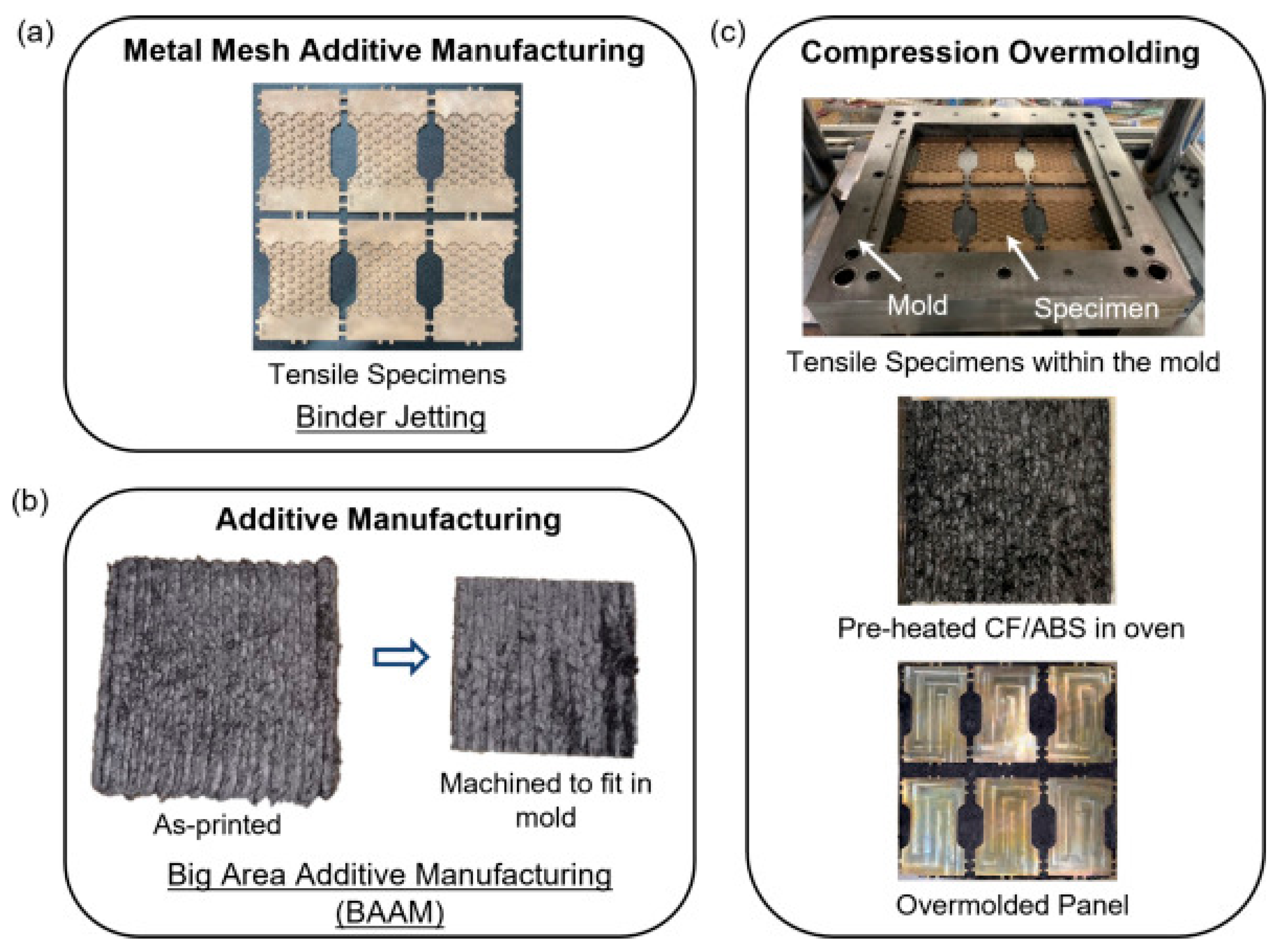
Figure 1. Additive Manufacturing–Compression Overmolding (AM–CM) process route: (a) fabrication of metal inserts using Binder Jetting, (b) production of polymer composite preforms via Material Extrusion (MEX), and (c) heating and compression overmolding of the polymer onto the metal inserts to form a hybrid structure. Reprinted from Pokkalla et al. [7].
Applsci 15 12176 g001
Figure 2. AM technologies in medical applications. (a) Medical models; (b) Implants; (c) Tools, instruments and parts for medical devices; (d) Medical aids, supportive guides, splints and prostheses; (e) Biomanufacturing. Adapted from Salmi M. [11] (CC BY).
Applsci 15 12176 g002
Figure 3. AM technologies in aerospace applications. Additive manufacturing of the fuselage: (a) 3D printing of the stabilizer; (b) stabilizer—elevator assembly; (c) 3D printing of ruder; (d) vertical stabilizer—ruder assembly. Assembling the fuselage sections: (e) initial assembly of the fuselage—rudder—stabilizer; (f) assembling the front sections. Adapted from Zaharia S.M. [19] (CC BY).
Applsci 15 12176 g003
Figure 4. Additive manufacturing technologies in architecture field. Adapted from Zaharia S.M. [24].
Applsci 15 12176 g004
Figure 5. Fused Filament Fabrication (FFF) technology.
Applsci 15 12176 g005
Figure 6. Mechanical structure of fused deposition modeling technology: (a) Gantry Structure(based on LH Stinger open-source design); (b) Polar Coordinate Structure(based on Circa-3D-Printer); (c) Delta Structure(based on TriNS Delta 3D Printer); (d) CoreXY Structure (based on VZBot330 design) [41,42,43,44] (CCBY).
Applsci 15 12176 g006
Figure 7. Comparison of mesostructures: (a) part printed; (b) XZ cross section; and (cf) component cross section diagram. Parameters below: hot-end temperature/print speed/layer height. Scale bar = 1 mm. Reprinted from Abbott [87].
Applsci 15 12176 g007
Figure 8. Thermal management issues in high-speed additive manufacturing.
Applsci 15 12176 g008
Figure 9. Comparison of part surface quality before and after external vibration application. The red dashed circles mark vibration-induced defects—periodic ripples on the vertical walls, layer-to-layer banding, and corner rounding waviness. Reprinted from Jensen [93] (CCBY).
Applsci 15 12176 g009
Figure 10. Factors affecting printing accuracy and mechanical strength.
Applsci 15 12176 g010
Figure 11. Wire co-extrusion system integrated into the BAAM system: (a) Integrated wire coextrusion tool and extruder mounted on BAAM gantry and (b) Schematic of the BAAM single screw extruder with wire co-extrusion system. Reprinted from Billah [103].
Applsci 15 12176 g011
Figure 12. The specific process of optimizing fuzzy PID control by using particle swarm optimization algorithm. Reprinted from Liu [108].
Applsci 15 12176 g012
Figure 13. Multi-color printing vibration optimization. (a,b) comparison of printing accuracy before and after optimization; (c) comparison of natural frequency results before and after optimization; (d) comparison of mode shape displacement results before and after optimization. Adapted from Zhang [116] (CCBY).
Applsci 15 12176 g013
Figure 14. Multi-resolution printing. (a) schematic showing two selectable melt-flow paths: left, flow routed to the large-diameter port for high-throughput; right, flow routed to the small-diameter port for fine features; (b) magnified example of a part printed with a dual-port nozzle. Adapted from Chesser [125].
Applsci 15 12176 g014
Table 1. The categories of additive manufacturing technology.
Main CategorySub-CategoryCharacteristicsApplicable Fields
Vat Photopolymerization (VPP) [29]Stereolithography (SLA)
Digital Light Processing (DLP)
Continuous Liquid Interface Production (CLIP)
High precision and smooth surface but limited to photopolymer resins and high equipment costs.Precision prototypes, dental models, jewelry design, and biomedical scaffolds.
Material Jetting (MJT) [30]PolyJetSupports multi-material/multi-color with superior surface quality but has high material costs and weak mechanical properties.Full-color prototypes, medical models, multi-material composite parts combining soft and rigid regions, and educational models.
Binder Jetting (BJT) [31]Metal Binder JettingCapable of printing large-scale parts, but low part strength.Sand casting molds, architectural structures, and lightweight metal components.
Material Extrusion (MEX) [32]Fused Filament Fabrication (FFF)
Fused Granulate Fabrication (FGF)
Direct Ink Writing (DIW)
Big Area Additive Manufacturing (BAAM)
Low cost and material accessibility, but lower precision and anisotropic mechanical properties.Educational tools, prosthetics, and customized consumer products.
Sheet Lamination (SHL) [33,34]Laminated Object Manufacturing (LOM
Ultrasonic Additive Manufacturing (UAM)
Suitable for low-cost large-scale parts but has weak interlayer bonding and rough surface.Metal laminated parts (electronic packaging), large-scale models, and functionally graded materials.
Powder Bed Fusion (PBF) [35]PBF-LB/P (Laser Beam, Polymers)
PBF-LB/M (Laser Beam, Metals)
PBF-EB/M (Electron Beam, Metals)
Enables fabrication of high-density, geometrically complex metal parts; requires expensive equipment; relatively low powder utilization.Aerospace components (turbine blades), biomedical implants (titanium alloys), high-temperature alloys, and lightweight structures.
Directed Energy Deposition (DED) [36]DED-LB/M (Laser Beam)
DED-EB/M (Electron Beam)
DED-Arc (Arc Energy/Wire Feed)
Suitable for high-speed repair of large parts but requires post-processing due to rough surface and low precision.Large metal part repairs (turbine blades), aerospace structural components, weapon manufacturing, and functionally graded material coatings.
Table 2. Structural characteristics and performance trade-offs of common MEX printer architectures.
ArchitectureMain Advantages Main LimitationsKey Considerations for High-Speed Printing
GantrySimple calibration; low cost; and easy to manufactureLarge bed mass; vibrations likely during high-speed reciprocating motionReduce heated-bed mass; reinforce frame rigidity
PolarSimple mechanism; high precision for rotational and axisymmetric partsLimited precision for fine geometric details due to rotational kinematicsUse lightweight rotating platforms; optimize airflow and structural balance
DeltaLightweight moving mass; independent actuation; and high space utilizationKinematic coupling and dynamic vibration depend on position; calibration complexityIncrease system stiffness; apply vibration compensation techniques
Core XYStable frame; reduced printing-force bias and torsional effects; and well-suited for high-speed operationComplex belt routing may cause diagonal motion errors if misalignedMinimize printhead mass; ensure precise and symmetric belt configuration
Table 3. Different materials for FFF technology.
MaterialPerformance CharacteristicsApplication Fields
PLA (Polylactic Acid)Excellent biodegradability, non-toxic, and low shrinkage rate; poor heat resistance, high brittleness, and low toughness.Educational models, handicrafts, medical applications (e.g., dental molds), and eco-friendly packaging materials [51,52].
ABS (Acrylonitrile Butadiene Styrene)High strength (tensile strength ≥ 30 MPa), impact resistance, and moderate heat resistance; requires high-temperature printing and enclosed chamber.Automotive component prototypes, electronic product housings, tool handles, and drones [53,54].
PETG (Polyethylene Terephthalate Glycol)High transparency, impact resistance, and chemical corrosion resistance.Food packaging containers, industrial protective covers, and consumer electronics housings [55].
TPU (Thermoplastic Polyurethane)The material exhibits softness with high elasticity and excellent wear resistance yet presents high-forming difficulty during printing.Flexible seals, wearable device components, and shock-absorbing structures [56,57].
PA (Polyamide) Superior wear resistance, impact resistance, high strength, and high toughness.Drone propellers, mechanical gears, and high-performance industrial components [58].
PC (Polycarbonate)High-temperature resistance, impact resistance; requires enclosed printing environment.Automotive lamp covers, optical lenses, and protective equipment [59].
PEEK (Polyether Ether Ketone)Ultra-high strength, extreme heat resistance, and biocompatibility; requires specialized high-temperature printers.Orthopedic implants, aerospace engine components, and high-stress industrial parts [60,61,62].
Disclaimer/Publisher’s Note: The statements, opinions and data contained in all publications are solely those of the individual author(s) and contributor(s) and not of MDPI and/or the editor(s). MDPI and/or the editor(s) disclaim responsibility for any injury to people or property resulting from any ideas, methods, instructions or products referred to in the content.