1. Introduction
Hierarchically porous polymers are materials that integrate different scale voids within a single body to unlock exceptional combinations of surface area, mass-transport capability, and mechanical compliance that are central to next-generation catalysts, energy devices, biomedical scaffolds, and lightweight structural lattices [
1,
2,
3,
4].
Traditional foaming with blowing agents, solvent casting, or particulate-leaching routes can create micro- or macropores independently, yet they struggle to orchestrate the full spectrum of pore sizes, orientations, and connectivity demanded by truly multifunctional parts. Additive manufacturing (AM) has therefore attracted intense interest as a route to precise control over architecture [
5,
6]. Among the available AM technologies, Fused Filament Fabrication (FFF) stands out for its low cost, open-hardware ecosystem, and ability to process an ever-expanding palette of thermoplastics and composites [
7,
8,
9,
10,
11,
12].
Recent work shows that shell-lattice and functionally graded unit cell scans endow FFF prints with architected macroporosity while retaining geometric freedom and mechanical integrity [
13,
14,
15,
16]. Nevertheless, extrusion-based deposition alone rarely generates pores less than 100 µm that govern diffusion, acoustic damping, or cell ingrowth. To bridge this gap, researchers have begun to integrate FFF with complementary material chemistries and post-processing steps, filaments pre-loaded with physical [
17,
18] or chemical blowing agents [
19,
20], hollow microspheres [
21,
22], and sacrificial porogens [
23,
24] to enable in situ generation of multiscale porosity.
These functional filaments can be produced using a wide range of polymers driven by the availability of nearly all common thermoplastics in ready-to-print filament form [
25]. At entry level, makers still rely on PLA and ABS, yet enclosed desktop and industrial machines routinely process PETG, nylon, polycarbonate, and TPU, while chambers held above 200 °C extend the palette to PEI and PEEK for aerospace and sterilized medical hardware [
26]. Mechanical test campaigns show that carbon-fiber-reinforced polyamides printed by FFF can exceed 0.5 GPa in ultimate tensile strength [
27]; likewise, conditioned PETG rivals the toughness of molded ABS, and carefully tuned PEEK parameters let printed parts retain more than 80% of the strength of injection-molded counterparts [
28]. Meanwhile, flexible TPU, conductive graphene-loaded blends, and recycled or bio-sourced composites are moving from niche studies into commercial catalogues, signaling a maturation of the filament supply chain [
29]. By combining the aforementioned materials with complementary methods to produce hierarchical porous polymers, the capabilities of FFF expand: the designed lattice defines global geometry and load paths, while microcells within the struts increase surface area and mass transport, allow local tuning of stiffness and energy absorption, and enable functions such as tissue integration, filtration, and thermal or acoustic damping that geometry alone cannot deliver.
This article reviews the various techniques that can be integrated with fused filament fabrication (FFF) to produce polymer components featuring hierarchical porosity. Where previous surveys isolated lattice strategies from foaming approaches, this review article brings them together in a unified analysis. It begins with a brief overview of FFF fundamentals, emphasizing how key printing parameters affect the development of millimeter-scale voids in single-material prints, features that ultimately define the upper bounds of structural porosity. The discussion then shifts to porous polymers and the experimental methods used to characterize porosity. A clear grasp of these metrics is crucial for aligning printing strategies with functional requirements, whether aimed at maximizing lightweight stiffness, enabling fluid transport, or promoting biological integration. The central section of the paper categorizes the design strategies that facilitate multi-scale porosity through the use of functional filaments in FFF. For each strategy, the article details the fabrication process and presents relevant case studies, providing practical guidance for selecting the most appropriate method. A comparative analysis follows, examining performance trade-offs across different approaches. The final section addresses current limitations and highlights emerging solutions, concluding with perspectives on future developments in the field.
2. Fundamentals
2.1. Fused Filament Fabrication (FFF)
Fused Filament Fabrication (FFF) builds three-dimensional parts by extruding a molten thermoplastic filament through a heated nozzle and depositing it layer-by-layer along computer-generated toolpaths [
30]. Since Crump’s pioneering patent in 1992, successive generations of both open-source desktop printers and industrial machines have driven down capital costs and broadened adoption [
31]. Contemporary FFF systems rival other AM modalities with sub-100 µm layer heights, dual- or multi-material co-printing, closed-loop temperature control, and real-time optical/thermal monitoring [
32]. Recent comprehensive reviews highlight the migration of FFF beyond rapid prototyping toward functional production parts, accelerated by emerging variants such as “metal FFF,” where a metal-powder-loaded polymer is printed and subsequently sintered to near-full density [
33]. Market analysts predict that FFF will remain the dominant AM platform through at least 2030, largely because of its low entry barrier, rich ecosystem of third-party filaments, and sustained hardware innovation [
34].
Part quality and performance in FFF are governed by a tightly coupled set of process parameters. Systematic factorial and response-surface studies consistently rank layer thickness, nozzle temperature, bed temperature, and print speed (
Figure 1) as the most influential, jointly dictating bead geometry, inter-road fusion, porosity, and build time [
35]. For PLA and PETG, lowering the layer height to ≤0.2 mm and raising the nozzle temperatures by 10–20 °C typically boost tensile strength by 10–30% owing to improved interlayer diffusion, whereas excessive print speeds (>80 mm s
−1) or large raster angles (≥60°) tend to exacerbate anisotropy and surface roughness [
36]. Multi-objective optimizations that blend design of experiments with machine-learning regression now predict parameter windows that simultaneously minimize warpage and maximize strength, cutting empirical trial-and-error by up to 70% [
37]. Recent work further shows that for high-temperature polymers such as PEEK, maintaining a chamber temperature above the glass-transition temperature and employing slow cooling are essential to suppress shrinkage and maximize crystallinity [
38,
39].
The materials palette available for FFF has expanded dramatically. Commodity PLA and ABS remain popular for low-cost prototyping, but engineering thermoplastics such as PETG, TPU, nylon-6/12, polycarbonate, and aerospace-grade PEI and PEEK are now routinely processed on enclosed-chamber or high-temperature platforms [
40]. In addition, mechanical performance can be elevated through short- or continuous-fiber reinforcement: [
41,
42]. Beyond structural metrics, filament developers are introducing novel functionalities such as electrically conductive graphene blends, recycled or bio-sourced composites, and metal- and ceramic-loaded binders for post-sintering densification and concurrently pursuing greener life-cycle footprints through the use of biobased matrices and closed-loop recycling schemes [
43,
44].
2.2. Porosity Overview
Porosity in polymeric media can be categorized along four complementary descriptors: (i) pore-size, (ii) void (number or volume) density, (iii) connectivity (open, closed, percolating), and (iv) orientation (random vs. designed), as shown in
Figure 2 [
45]. Chemists traditionally adopt the IUPAC gas-adsorption scale [
46] categorizing micropores < 2 nm, mesopores 2–50 nm, and macropores > 50 nm, but a recent terminology survey for polymer systems stresses that these limits shift with mechanical and transport length scales [
47]. General materials-science texts add a geometric division into microporosity and macroporosity [
48]. For the purposes of this review, a pragmatic convention is followed: microporosity spans voids on the micro-scale (sub-100 µm), while macroporosity denotes architected or stochastic pores visible at the macro-scale (>100 µm).
For quantifying porosity in polymers, the simplest route is a gravimetric weight-to-volume balance such as the Archimedes buoyancy for bulk density or helium/gas pycnometry for skeletal density, which show total (open and closed) porosity when coupled to nominal sample dimensions [
49]. Nondestructive imaging, notably X-ray micro-computed tomography (µCT), now resolves 3-D pore morphologies to below 1 µm, enabling voxel-based statistics of size, connectivity, and orientation with recent threshold-free segmentation algorithms pushing accuracy <2% porosity error [
50]. Complementary SEM correlative workflows extend this reach to the nano-regime and allow direct validation of mathematical cellular-solid models and percolation simulations that relate porosity to stiffness and permeability [
51,
52].
For the conventional fabrication of porous polymers, industrial and biomedical platforms rely on a toolkit of thermodynamic or kinetic phase-separation routes: solvent casting/particulate (salt or sugar) leaching, thermally induced phase separation, super- or sub-critical CO
2 gas foaming, ice/solvent freeze-drying (lyophilization), and high-internal-phase emulsion (HIPE) polymerization [
53,
54]. Electrospinning and centrifugal spinning create interconnected fibrous macro-/microporosity with tunable orientation, whereas additive-manufacturing strategies offer control over pore architecture and density [
55]. Process-structure studies show that reducing porogen size or increasing saturation pressure narrows cell distribution and raises compressive strength, while bimodal micro-/macroporous scaffolds fabricated via combined gas-foaming–particulate-leaching routes deliver superior nutrient transport for tissue engineering [
56,
57].
3. Strategies for Creating Hierarchical Porous Structures in FFF
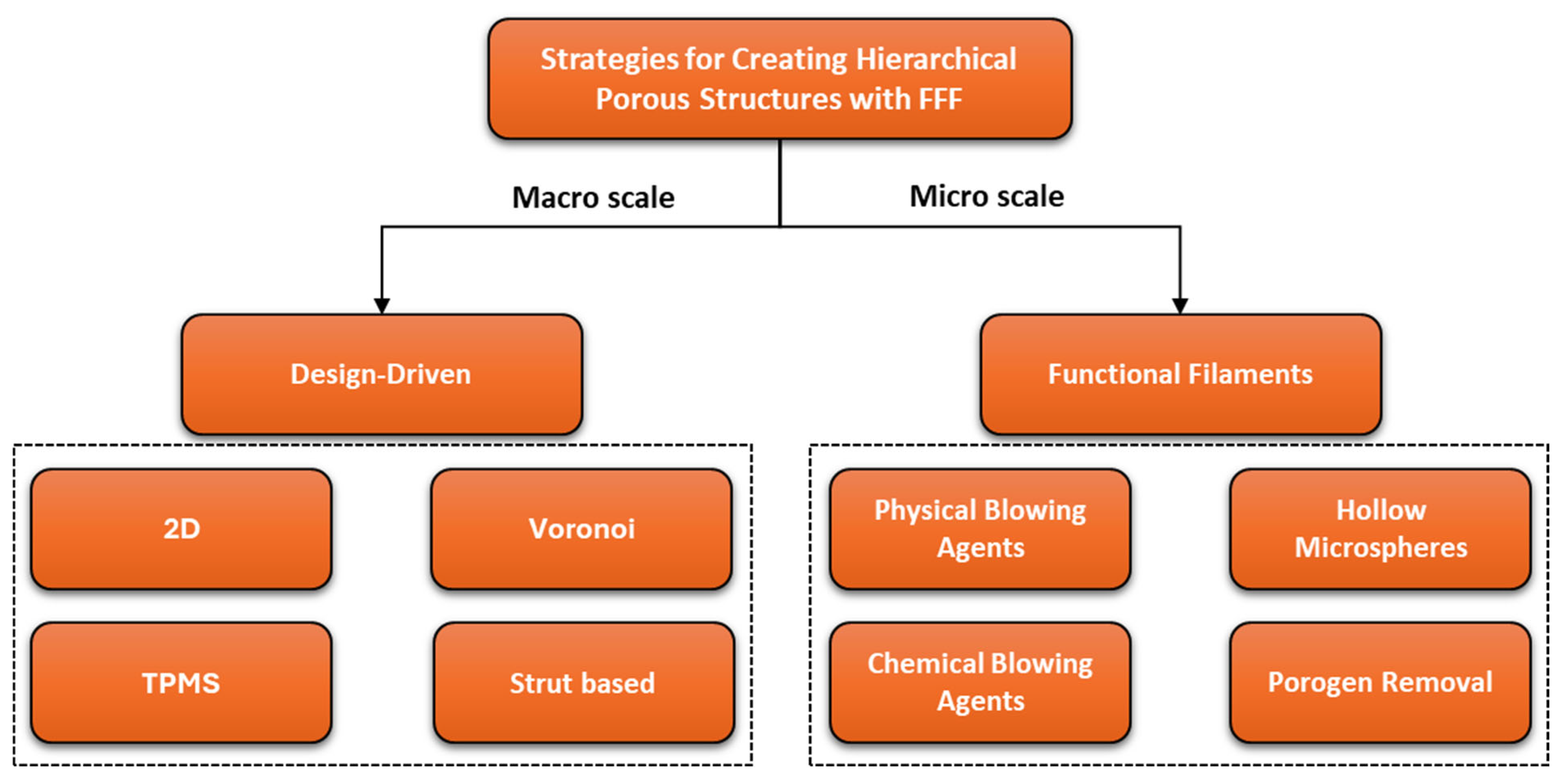
There are multiple methods to create porosity with varying sizes, shapes, and degrees of interconnectivity. Some of these techniques can generate multi-scale porosity simultaneously. When two or more methods are combined, they can also produce hierarchical porosity, with each technique contributing distinct structural features. This study outlines the various approaches for creating hierarchical porosity with fused-filament fabrication (FFF), as presented in
Figure 3. Design-driven approaches create pores by prescribing toolpaths that place material only where needed, leaving voids elsewhere. In contrast, functional-filament approaches use specialty materials that either already contain pores or generate randomly distributed porosity during or after printing. At the millimeter scale, FFF can deliberately introduce pores in a range of predefined architectures, while functional filaments make it possible to incorporate micron-scale porosity. The subsections that follow describe first, the design-based techniques for generating porosity, and second, the functional filaments that can be paired with those techniques.
3.1. Design-Driven FFF Strategies
3.1.1. Porous Designs via FFF
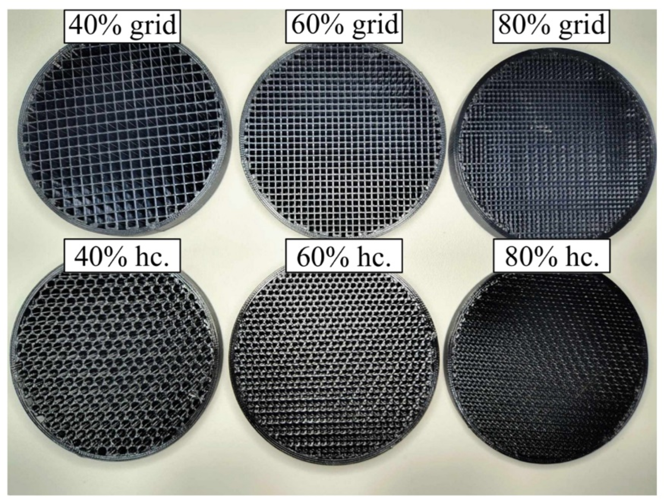
On a typical desktop FFF printer, porosity can be created by replacing solid regions with planar (2D) infill patterns. For example, patterns like hexagonal honeycombs, re-entrant auxetics, sinusoidal/curvilinear paths, or triangular grids can be utilized [
58,
59]. The extruder lays continuous filament paths that form cell walls. The gaps between adjacent roads become macro-scale pores. Pore size is mainly governed by nozzle diameter/line width, line spacing, and layer height, along with infill density/pattern, so open porosity can be raised without sacrificing geometric fidelity. Representative FFF samples with different infill densities and infill patterns (grid and honeycomb) are shown in
Figure 4.
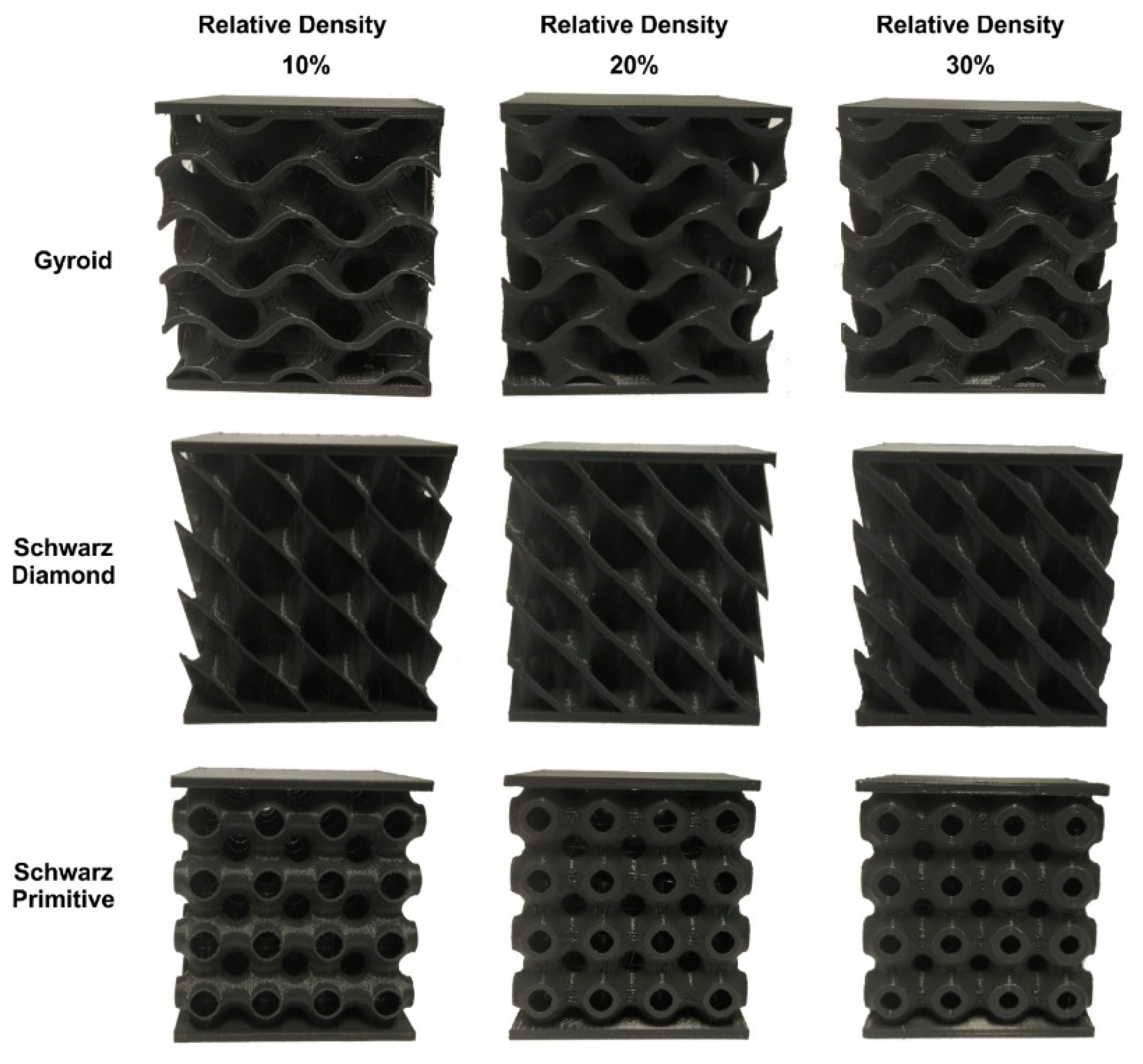
Triply Periodic Minimal Surfaces (TPMS), such as Gyroid, Schwarz-P, and Diamond, provide a fully 3D route to porosity. They are defined by implicit equations; porosity is tuned via wall thickness and unit-cell size [
61,
62]. TPMS generally print well by FFF, but local overhangs and orientation can dictate support needs and performance differences among sheet vs. skeletal variants. Representative FFF samples with different infill densities and different TPMS infill patterns (grid and honeycomb) are shown in
Figure 5.
Alternatively, porosity can be achieved using regular strut-based lattices like cubic, body-centered cubic (BCC), face-centered cubic (FCC), octet truss, and Kelvin structures [
64,
65]. In these, straight struts connect at nodes, and porosity is tuned by modifying strut thickness and unit cell size. Their manufacturability using FFF also depends on structural complexity and the need for support during printing. Representative FFF samples with different strut-based lattices are shown in
Figure 6.
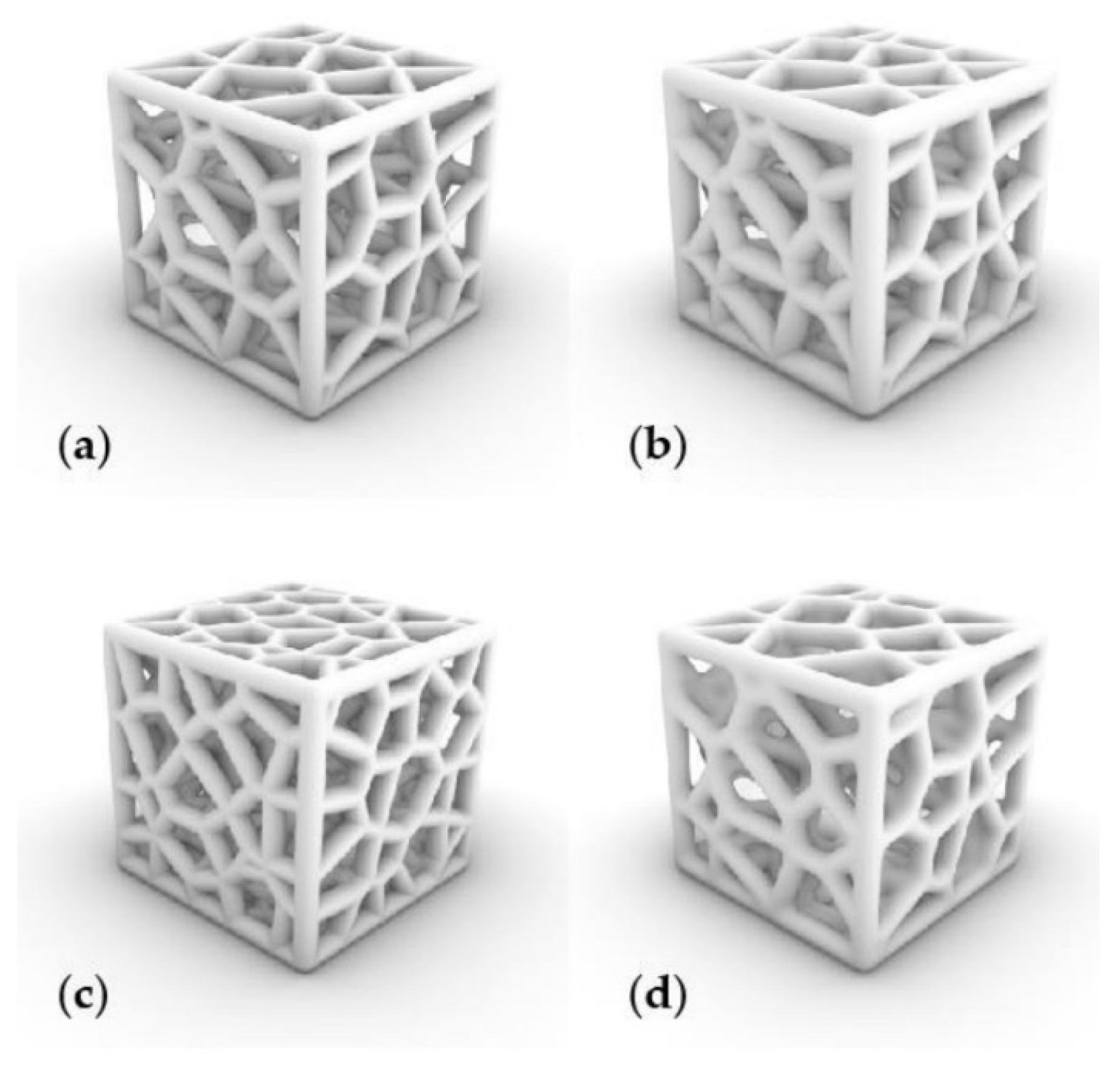
A more irregular but design-driven option involves generating Voronoi-based structures. By placing seed points and tessellating the space, the resulting Voronoi edges form a network of struts [
67]. While inherently random, these structures offer tunable porosity by adjusting the density of seed points and the thickness of connecting struts, making them well-suited for custom, FFF-compatible porous designs [
68].
Figure 7 shows representative Voronoi models printable by FFF, generated with varying parameter sets.
Table 1 summarizes the design-driven FFF strategies alongside their representative geometries. For each approach, key parameters governing porosity are listed. Brief printability notes are also provided, highlighting overhang constraints, support needs, and orientation effects.
3.1.2. Achieving Hierarchical Porosity Solely via FFF
Hierarchical porous structures spanning several length scales can be fabricated with Fused Filament Fabrication alone, relying on a single standard thermoplastic and no specialized functional filaments. By adjusting printing parameters, such as infill density, pattern, layer height, nozzle diameter, and extrusion rate porosity can be spatially varied within a part without altering the base material. This makes FFF especially useful for applications requiring functionally graded materials or site-specific mechanical performance. Buj-Corral et al. [
69] demonstrated how varying nozzle diameter and infill percentage significantly affects porosity and pore size in rectilinear PLA lattices, with results confirmed via X-ray microtomography. Palić et al. [
70] further explored functionally graded porous structures by dynamically changing infill and extrusion parameters during printing, producing PLA discs with gradual porosity transitions. Lalegani Dezaki et al. [
71] compared CAD-defined and slicer-generated infill patterns, showing that geometric design choices strongly influence internal porosity and mechanical properties. Aboelella et al. [
72] investigated the effect of layering different infill patterns and densities within PLA parts, demonstrating how combined pattern orientation and density modulation can control porosity distribution and interlayer bonding.
Figure 8 clearly illustrates that PLA samples produced via 3D printing can have distinct infill regions isolated through this approach, leading to structures that combine pores with multiple sets of predefined characteristics [
73]. These studies confirm that multi-scale porosity in FFF can be engineered through design and process control alone, enabling material-efficient structures with tailored performance using a single polymer system.
Nonetheless, there is a fundamental constraint on the minimum pore size attainable with this method. Because the strands are laid down through a nozzle whose diameter, extrusion swell, layer height, and thermal bonding all impose geometric limits, pores much below roughly 150–200 µm either fuse closed or lose dimensional accuracy, even when using the smallest practical nozzles and finely tuned print parameters. Consequently, FFF on its own excels at generating millimeter- and sub-millimeter-scale porosity, but it cannot reliably enter the true microporous regime.
3.2. Functional Filaments
Beyond geometric control, hierarchical porosity can be achieved in Fused Filament Fabrication (FFF) through the use of functional filaments containing porosity-inducing additives. These additives generate microporosity during the extrusion and deposition phases of FFF or afterwords through a postprocess method, as shown in
Figure 9. Micropores from these additives arise from how the filament heats, flows, and cools. In addition, bubbles may form or fillers may be removed later, which sets pore size and connectivity. Moreover, toolpaths and layer lines guide micropore alignment, so properties depend on orientation. When combined with macroporosity introduced via design (e.g., lattice structures, low infill), the result is a multi-scale porous architecture generated in a single-step or multi-step process. The following sections outline how each additive category is integrated with FFF to enable hierarchical porosity.
3.2.1. Filaments with Chemical Blowing Agents
CBAs are thermally activated compounds that decompose during extrusion to release gases, typically CO
2 or N
2, resulting in the formation of microbubbles within the extruded filament strand. In the context of FFF, CBAs are incorporated into the thermoplastic feedstock through melt compounding, followed by filament extrusion. During printing, the thermal environment within the nozzle triggers gas release, leading to in situ foam formation. When combined with infill-based macroporosity, CBA-induced foaming provides a secondary level of porosity within each extruded bead. Damanpack et al. [
74] successfully produced foamed PLA scaffolds by varying print temperature and flow rate to modulate pore morphology. Similarly, Kalia et al. [
75] reported that increasing the CBA content and using slower deposition speeds resulted in more uniform pore structures. Tammaro et al. [
76] highlighted the importance of nozzle residence time and temperature gradients for stable foam generation. Honari et al. [
77] used CBA to simultaneously 4D print and in situ foam PLA for tailoring shape memory behaviors. These studies demonstrate that with proper process control, CBAs can be effectively combined with FFF to generate hierarchical pore networks within printed structures.
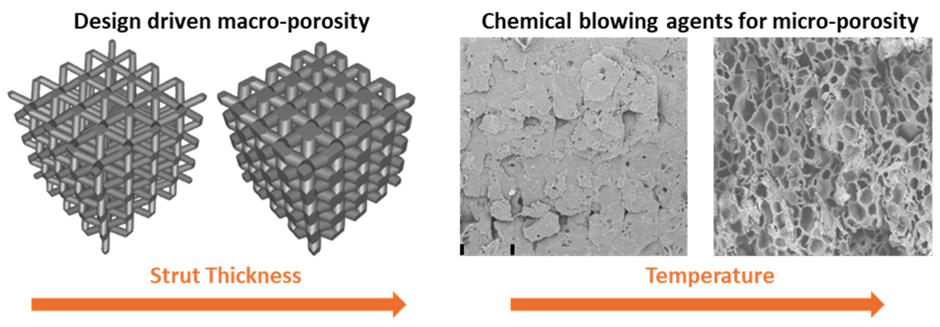
Figure 10 illustrates that raising the nozzle temperature activates a chemical-blowing-agent filament to generate micropores and shows how this effect can be paired with a body-centered-cubic lattice whose strut thickness is varied to tailor the macroporous framework [
78].
3.2.2. Filaments with Physical Blowing Agents
PBAs such as supercritical CO
2 or N
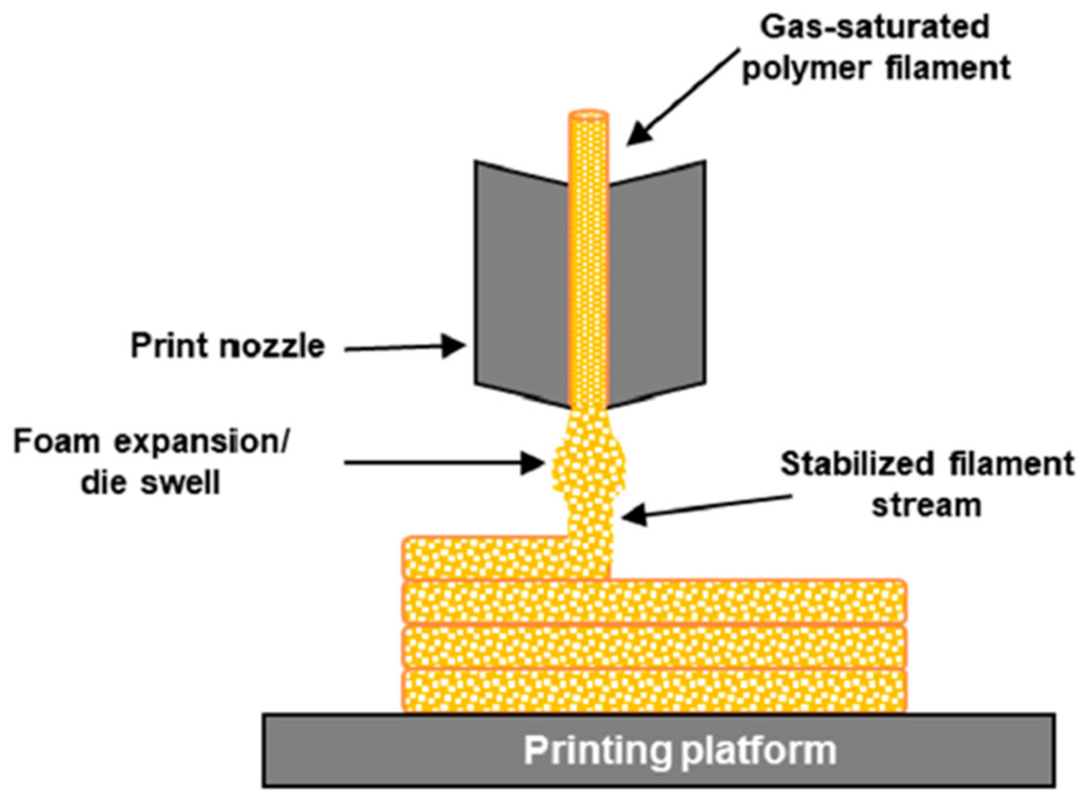
2 can be used to impregnate polymer filaments with gas under high pressure prior to printing. During FFF, the rapid pressure drop in the heated nozzle causes the gas to expand and nucleate bubbles, creating microporosity. This process is illustrated in
Figure 11 [
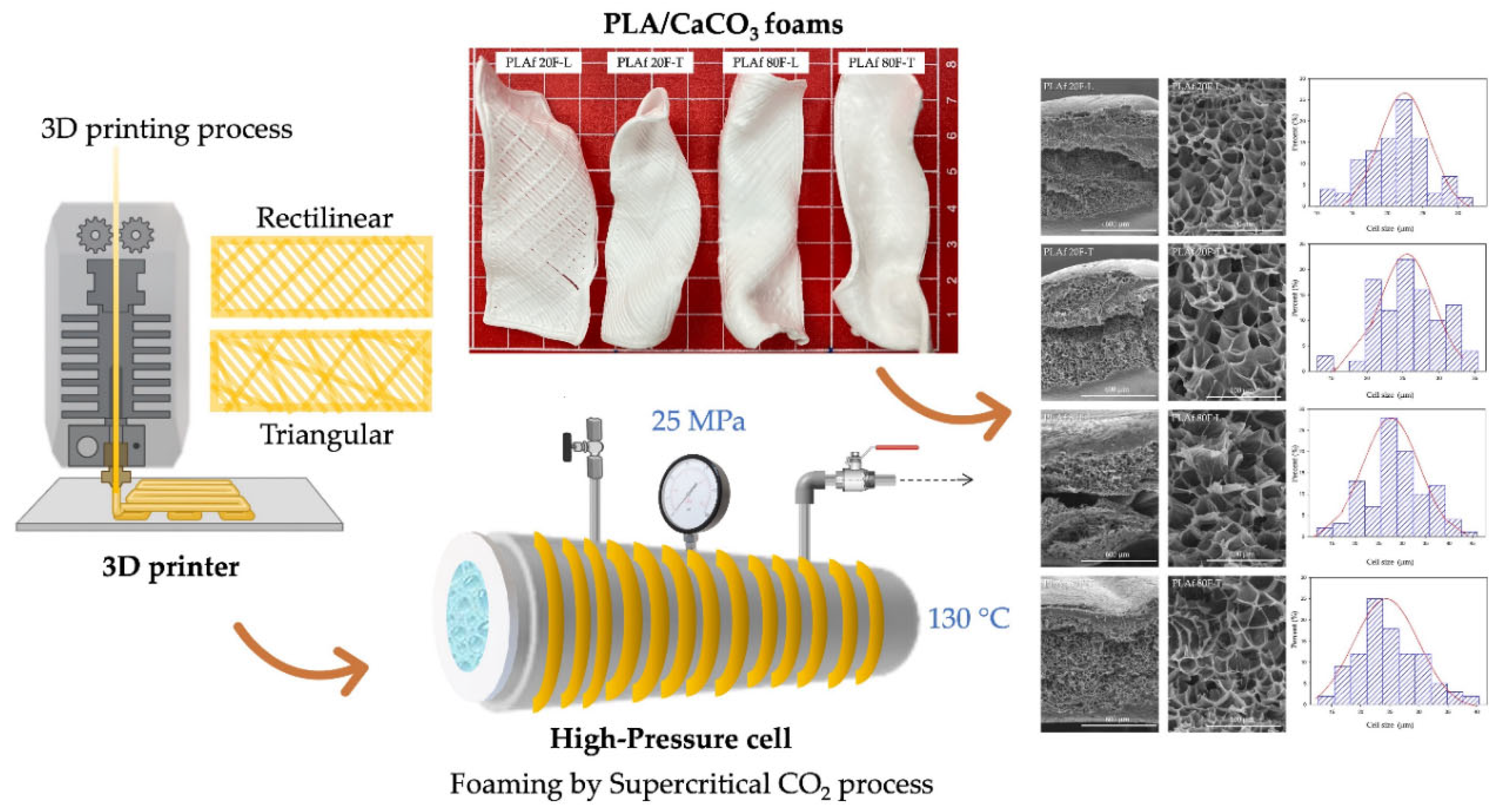
79]. This process requires pre-treatment of filaments using gas-loading chambers or continuous saturation systems. Another less popular route is to print parts from standard, non-foaming filaments and then create porosity afterward by placing the prints in a high-pressure gas chamber as shown in
Figure 12 [
80].
In batch chambers, the material is held under CO2 or N2 at elevated pressure and controlled temperature so gas dissolves into the polymer, with the required time set by polymer chemistry and filament diameter. After saturation, the vessel is depressurized in a controlled way to retain dissolved gas and avoid premature foaming. In continuous systems, the filament passes through a pressurized and temperature-controlled tunnel that maintains steady gas uptake and then feeds directly to the printer. Bubble nucleation during FFF depends on dissolved gas content, the pressure drops from chamber to nozzle, the temperature profile in the nozzle, shear and residence time, and the cooling rate after deposition.
Zhai et al. [
81] reported CO
2-saturated PEI filaments enabling in-situ foaming FDM of honeycomb structures. Radhakrishna et al. [
82] utilized CO
2-gas-saturated PLA filament to FDM-print honeycomb parts that exhibited microcellular porosity. These studies confirm that PBAs can effectively introduce micro-scale pores during FFF, contributing to hierarchical porosity when used in tandem with macro-structural design.
Thermally expandable microspheres (TEMs) can also be considered PBAs. They are incorporated into filaments as a masterbatch. Upon reaching a threshold temperature in the printer nozzle, these microspheres expand, creating uniform microcellular pores in the extrudate. TEMs expand only during the printing process, requiring precise thermal control. Kalia et al. [
83] produced PLA microcellular structures by FFF using filaments pre-loaded with thermally expandable microspheres (TEMs); the in-situ expansion created foamed struts while preserving the designed part geometry, and by varying TEM content and nozzle temperature they tuned foam density. Andersson et al. [
84] presented this technique as a scalable option for creating lightweight components without secondary processing. Nofar et al. [
85] emphasized that process variables such as print speed, nozzle diameter, and layer time significantly affect foam morphology. When used alongside standard slicing strategies for structural design, in situ TEM expansion allows the fabrication of truly hierarchical porous architectures within the FFF framework.
3.2.3. Filaments with Hollow Microspheres
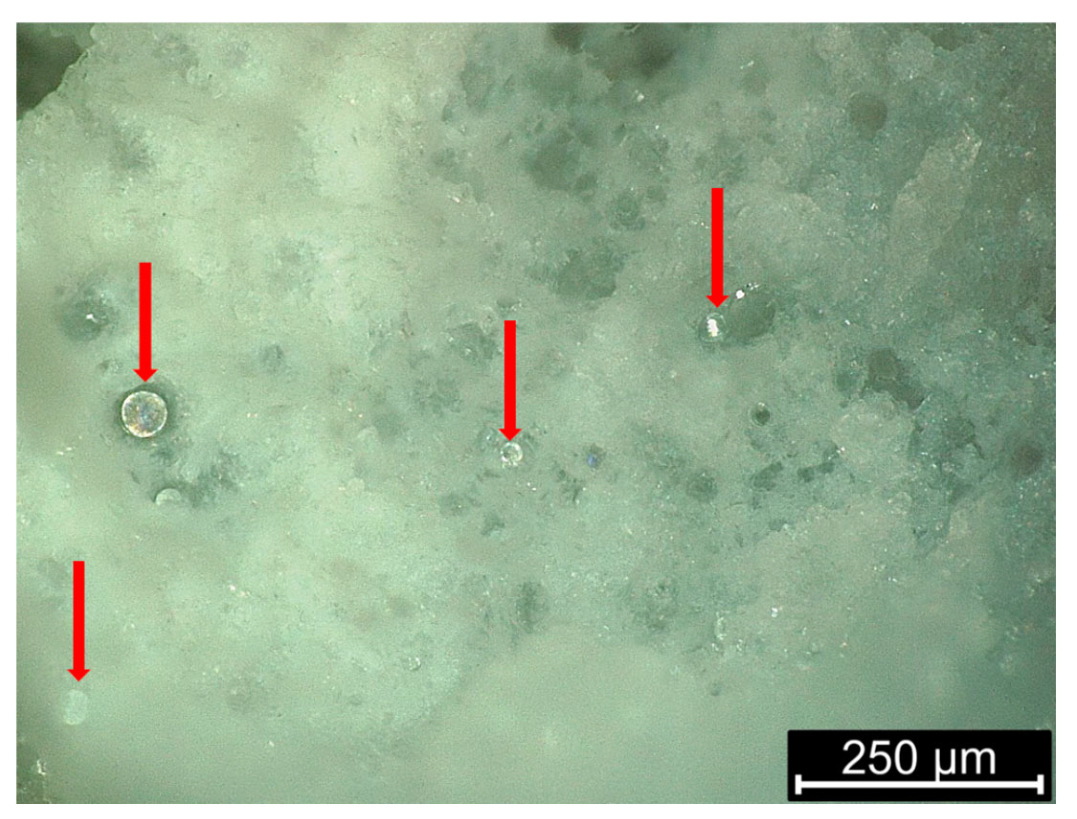
Hollow microspheres can be mixed into the polymer matrix prior to filament extrusion. During FFF, the microspheres remain intact within the polymer melt and are embedded into the extruded strands, contributing microporosity based on particle size and volume fraction. Bharath et al. [
86] developed HDPE filaments filled with up to 60 vol% glass microballoons, observing significant reductions in part density with minimal loss in mechanical integrity.
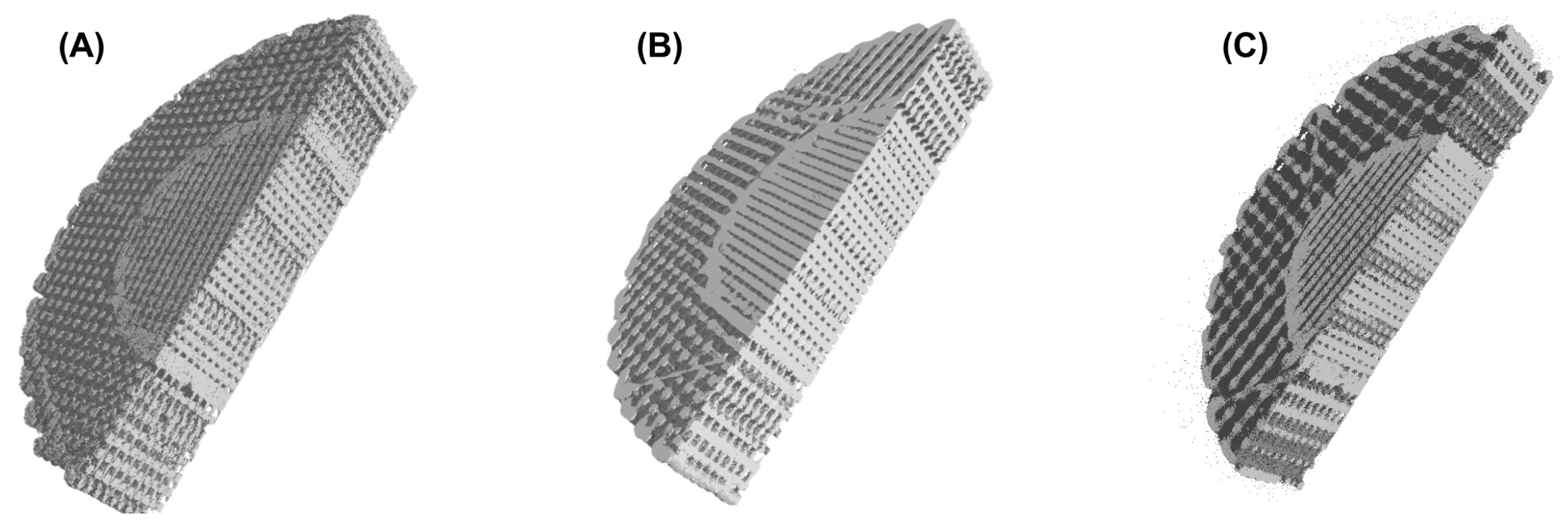
Figure 13 presents an example of a PCL filament loaded with hollow glass microspheres [
87]. In all cases, the microspheres complement design-driven porosity by filling the printed strands with discrete internal voids, adding another hierarchical level to the structure.
3.2.4. Filaments with Porogens
Porogen removal is a post-processing strategy in which sacrificial materials are embedded into a polymer matrix during filament preparation or printing and subsequently removed to generate pores. In the context of FFF, this technique allows for the controlled formation of micropores within parts that already possess macro-scale architecture defined by the print design. Porogens can be organic or inorganic and are typically leached out after printing via water immersion, solvent washing, or thermal decomposition. To integrate porogen removal with FFF, the porogen is first physically mixed or melt-blended with the base polymer to produce a composite filament. The resulting filament is printed using standard FFF parameters, during which the porogen remains dispersed but inactive. After printing, the structure undergoes selective removal of the porogen. For instance, Podgórski et al. [
88] compounded PEG into FFF feedstock and then water-leached PEG after printing, yielding micrometer-scale surface/strut pores without sacrificing scaffold geometry. The effectiveness of porogen removal depends on the compatibility of the porogen with the polymer, the porogen loading, and the leaching conditions (time, temperature, solvent type). Wang et al. [
89] combined 3D printing scaffolds with freeze-cast gelatin matrices, achieving microscale pores that enhanced cell culture.
Figure 14 shows the micro-CT analysis on hierarchical porous PCL structures fabricated by combining FFF with salt leaching [
90]. These methods enable functional zoning, where different regions of the part exhibit tailored pore architecture based on their biological or mechanical roles.
4. Comparative Evaluation
There are various approaches to creating structures that integrate both microporosity and macroporosity. This section aims to compare these methods in terms of how feasible they are to manufacturability.
Table 2 outlines the key advantages and disadvantages of each strategy. Starting with design-driven lattices leverage the printer’s toolpath to sculpt macroporosity, giving clear, simulation-friendly geometries and requiring only standard filaments. They excel when structural load paths, airflow, or fluid channels in the millimeter range dominate performance. Their limitation is the nozzle diameter since pores rarely dip below about 150 µm, leaving diffusion, capillarity, or cell-ingrowth functions underserved. However, this method allows for tailoring specific regions with different pore sizes or even achieving gradient porosity, as the design process offers full control over pore size and morphology.
Material-driven routes flip the paradigm. By embedding foaming agents, microspheres, or removable porogens in the filament, they introduce tens-of-microns pores inside each extruded road without altering the visible lattice. These chemistries yield low density and huge internal surface area but demand tighter thermal control, may introduce harmful byproducts or post-process steps, and can erode dimensional accuracy if foaming is not well tuned.
Within the material-driven family, each strategy offers a different balance of processing complexity, pore quality, and downstream impact. Chemical blowing agents (CBAs) are inexpensive masterbatches that foam vigorously with only a modest temperature bump, so they retrofit easily to any FFF machine; however, they leave gaseous byproducts that can embrittle hygroscopic polymers, and their reaction kinetics are sensitive to residence time, which narrows the printable window. Physical blowing agents (PBAs) introduce no chemical residues and let designers tune cell size simply by adjusting saturation pressure and print speed, yet they demand pressurized impregnation hardware and tight storage protocols to prevent premature gas loss. Thermally expandable microspheres (TEMs) expand sharply at a preset temperature, producing highly uniform, spherical cells without aggressive foaming gases; the trade-off is that microspheres must be well dispersed during compounding, and the resulting structure tends to be closed-cell, limiting permeability. Hollow microsphere fillers lower density independent of print temperature and add damping or insulation, but they create mostly isolated pores and can reduce filament toughness if the glass transition of the shell is approached during extrusion. Finally, sacrificial porogens yield fully open, interconnected micro-channels with precise size control, making them ideal for tissue-engineering scaffolds; their drawbacks are the extra leaching or burnout step, potential solvent use, and high shrinkage that must be compensated in the CAD model. Selecting among these options therefore hinges on whether the priority lies in single-step build speed (favoring CBAs or TEMs), cleanliness and residue-free chemistry (PBAs), mechanical damping (hollow spheres), or maximized permeability and bioactivity (porogens).
In practice, the most potentially capable hierarchical parts couple the two philosophies: a lattice sets the macroporous framework for mechanical integrity and flow, while porosity on a lower scale increases other properties such as surface area, damping, or biological affinity. Selecting the optimum mix depends on the dominant functional requirement such as load bearing, transport, and bioactivity as well as equipment constraints and finally regulatory environment and sustainability targets.
5. Challenges, Limitations, and Future Perspectives
Despite impressive progress, the hybrid manufacturing of hierarchically porous polymers via FFF still faces several materials-centered obstacles. Highly filled or foaming filaments demand specific viscosities to avoid nozzle clogging, yet the particles, blowing agents, and plasticizers often push viscosity far higher [
91,
92,
93]. Thermal gradients intrinsic to open-frame printers accentuate this problem by causing premature gas expansion or crystallization. Moreover, chemical blowing agents release moisture, acids, or CO
2 [
94] that can embrittle hygroscopic matrices such as PA-12, shortening filament shelf-life to mere weeks unless stored under vacuum.
A process-integration bottleneck arises when architected macroporous lattices are combined with in situ foaming. The exothermic decomposition of blowing agents raises the local melt temperature, altering bead width and jeopardizing dimensional accuracy; compensation strategies (real-time nozzle temperature modulation, dynamic flow-rate control) [
81]. Post-print debinding or porogen-leaching steps introduce additional shrinkage and often require toxic solvents [
95]. Finally, porosity quantification lacks standardization: density methods capture total void volume but miss connectivity; µCT struggles with nanoscale pores, while BET overlooks closed macro cells, yielding datasets that are difficult to compare across studies [
46].
Looking forward, digital and sustainable innovations promise to mitigate these hurdles. Physics-informed machine-learning models [
96] could predict melt-foaming behavior from rheology and thermal data,. Coupling such models with closed-loop infrared or acoustic monitoring [
97] could auto-correct extrusion parameters in milliseconds, taming stochastic pore growth. Gradient-extrusion print heads capable of on-the-fly filament compounding hint at single-step fabrication of lattices whose struts transition from solid to micro-cellular foam, could unlock unprecedented mechanical meta-properties [
98]. Considering all the above, a practical next step is to pair foaming with simple gradient infills to tune stiffness without complex chemistry. The main limitation is keeping pores uniform across layers, since small changes in heat or speed still have a big effect. A short set of shared benchmarks on a few test parts would make comparisons fair and speed progress. Moreover, in industrial settings, machine learning approaches can help with monitoring chamber temperature, nozzle temperature, melt pressure, or part weight to flag drift and gently adjust speed or heat within limits.
6. Conclusions
This review has provided a comprehensive overview of the strategies for fabricating hierarchically porous polymer structures by integrating fused filament fabrication (FFF) with complementary design and material-based methods. The combination of macroporosity introduced through geometric control (e.g., lattice infill, TPMS, Voronoi designs) and microporosity generated via functional filaments (e.g., chemical/physical blowing agents, microspheres, sacrificial porogens) enables the creation of complex, multi-scale architectures that surpass the limitations of traditional manufacturing approaches.
Multiple routes can create hierarchical porosity, but the most effective couples design-defined macropores with filament-induced micropores. Infill patterns and lattices set the millimeter to sub-millimeter framework, while chemical and physical blowing agents (including TEMs), hollow microspheres, and leachable porogens add pores at micron scales and smaller. This synergy bypasses the geometric lower bound of FFF alone and enables tunable gradients in size, connectivity, and orientation to match the target function. The key tradeoff is permeability and surface area versus interlayer bonding and strength, which can be managed through careful thermal control, toolpath planning, and post-processing. With thoughtful integration, these methods yield reproducible, application-specific porous parts on standard FFF equipment. Comparative analysis reveals that each approach carries distinct advantages and trade-offs. Design-driven lattices offer precise, simulation-friendly structures but are constrained by the nozzle’s geometric resolution. In contrast, material-driven strategies unlock finer pore scales and internal surface area but demand tighter process control and often involve additional post-processing. The most effective solutions combine both approaches, tailoring porosity at multiple scales to meet application-specific requirements in lightweight structures, biomedical scaffolds, and energy devices.
Despite recent advancements, several challenges remain, including viscosity management, foaming control, and the lack of standardized porosity characterization. However, emerging technologies—such as machine-learning-assisted process control, sustainable filament development, and hybrid printhead systems—show promise in overcoming these barriers. Continued research at the intersection of materials science, design engineering, and process optimization will be key to fully realizing the potential of FFF in fabricating hierarchical porous polymer structures.
Author Contributions
Conceptualization, S.K.; methodology, S.K.; software, S.K.; validation, S.K.; formal analysis, S.K.; investigation, S.K.; resources, S.K. and D.T.; data curation, S.K.; writing—original draft preparation, S.K.; writing—review and editing, S.K. and D.T.; visualization, S.K.; supervision, D.T.; project administration, D.T.; funding acquisition, D.T. All authors have read and agreed to the published version of the manuscript.
Funding
This research received no external funding.
Data Availability Statement
No new data were created or analyzed in this study. Data sharing is not applicable to this article.
Conflicts of Interest
The authors declare no conflict of interest.
References
- Romero, C.; Liu, Z.; Wei, Z.; Fei, L. A review of hierarchical porous carbon derived from various 3D printing techniques. Nanoscale 2024, 16, 12274–12286. [Google Scholar] [CrossRef]
- Ingram, M.; Campbell, E.; Molotnikov, A.; Feih, S.; Zhong, Y.L. Recent advances in multifunctional polymer/2D nanocomposite development for fused filament fabrication and direct ink writing of electrically and thermally conductive components. Adv. Nanocompos. 2024, 1, 157–170. [Google Scholar] [CrossRef]
- Cuan-Urquizo, E.; Silva, R.G. Fused filament fabrication of cellular, lattice and porous mechanical metamaterials: A review. Virtual Phys. Prototyp. 2023, 18, e2224300. [Google Scholar] [CrossRef]
- Koltsakidis, S.; Tsongas, K.; Tzetzis, D. Robocasting of Hierarchical Porous Al2O3 Structures: A Computational and Experimental Methodology for Porosity Estimation and its Effect. J. Mater. Eng. Perform. 2024, 34, 16284–16296. [Google Scholar] [CrossRef]
- Spadaccini, C.M. Additive manufacturing and processing of architected materials. MRS Bull. 2019, 44, 782–788. [Google Scholar] [CrossRef]
- Tao, W.; Ming, C.L. Design of lattice structure for additive manufacturing. In Proceedings of the 2016 International Symposium on Flexible Automation (ISFA), Cleveland, OH, USA, 1–3 August 2016. [Google Scholar]
- Singh, S.; Singh, G.; Prakash, C.; Ramakrishna, S. Current status and future directions of fused filament fabrication. J. Manuf. Process. 2020, 55, 288–306. [Google Scholar] [CrossRef]
- Dey, A.; Eagle, I.N.R.; Yodo, N. A review on filament materials for fused filament fabrication. J. Manuf. Mater. Process. 2021, 5, 69. [Google Scholar] [CrossRef]
- Kumar, S.; Singh, R.; Singh, T.P.; Batish, A. Fused filament fabrication: A comprehensive review. J. Thermoplast. Compos. Mater. 2023, 36, 794–814. [Google Scholar] [CrossRef]
- Yadav, A.; Rohru, P.; Babbar, A.; Kumar, R.; Ranjan, N.; Chohan, J.S.; Kumar, R.; Gupta, M. Fused filament fabrication: A state-of-the-art review of the technology, materials, properties and defects. Int. J. Interact. Des. Manuf. (IJIDeM) 2023, 17, 2867–2889. [Google Scholar] [CrossRef]
- Zirak, N.; Shirinbayan, M.; Deligant, M.; Tcharkhtchi, A. Toward polymeric and polymer composites impeller fabrication. Polymers 2021, 14, 97. [Google Scholar] [CrossRef]
- Ahmadifar, M.; Benfriha, K.; Shirinbayan, M.; Fitoussi, J.; Tcharkhtchi, A. Mechanical behavior of polymer-based composites using fused filament fabrication under monotonic and fatigue loadings. Polym. Polym. Compos. 2022, 30, 09673911221082480. [Google Scholar] [CrossRef]
- Wang, Y.; Zhang, L.; Daynes, S.; Zhang, H.; Feih, S.; Wang, M.Y. Design of graded lattice structure with optimized mesostructures for additive manufacturing. Mater. Des. 2018, 142, 114–123. [Google Scholar] [CrossRef]
- Shojaee, M.; Valizadeh, I.; Klein, D.K.; Sharifi, P.; Weeger, O. Multiscale modeling of functionally graded shell lattice metamaterials for additive manufacturing. Eng. Comput. 2024, 40, 2019–2036. [Google Scholar] [CrossRef]
- Dey, A.; Ramoni, M.; Yodo, N. A Survey on Fused Filament Fabrication to Produce Functionally Gradient Materials. Materials 2024, 17, 3675. [Google Scholar] [CrossRef] [PubMed]
- Fico, D.; Rizzo, D.; Casciaro, R.; Esposito Corcione, C. A review of polymer-based materials for fused filament fabrication (FFF): Focus on sustainability and recycled materials. Polymers 2022, 14, 465. [Google Scholar] [CrossRef] [PubMed]
- Coste, G.; Negrell, C.; Caillol, S. From gas release to foam synthesis, the second breath of blowing agents. Eur. Polym. J. 2020, 140, 110029. [Google Scholar] [CrossRef]
- Pantani, R.; Volpe, V.; Titomanlio, G. Foam injection molding of poly (lactic acid) with environmentally friendly physical blowing agents. J. Mater. Process. Technol. 2014, 214, 3098–3107. [Google Scholar] [CrossRef]
- Reglero Ruiz, J.A.; Vincent, M.; Agassant, J.F.; Sadik, T.; Pillon, C.; Carrot, C. Polymer foaming with chemical blowing agents: Experiment and modeling. Polym. Eng. Sci. 2015, 55, 2018–2029. [Google Scholar] [CrossRef]
- Wypych, G. Handbook of Foaming and Blowing Agents; Elsevier: Toronto, Canda, 2022. [Google Scholar]
- Ramli, R.A. Hollow polymer particles: A review. RSC Adv. 2017, 7, 52632–52650. [Google Scholar] [CrossRef]
- Wang, X.; Feng, J.I.; Bai, Y.; Zhang, Q.; Yin, Y. Synthesis, properties, and applications of hollow micro-/nanostructures. Chem. Rev. 2016, 116, 10983–11060. [Google Scholar] [CrossRef]
- Lakshmi, D.S.; Radha, K.S.; Castro-Muñoz, R. Emerging trends in porogens toward material fabrication: Recent progresses and challenges. Polymers 2022, 14, 5209. [Google Scholar] [CrossRef]
- Mansour, F.R.; Waheed, S.; Paull, B.; Maya, F. Porogens and porogen selection in the preparation of porous polymer monoliths. J. Sep. Sci. 2020, 43, 56–69. [Google Scholar] [CrossRef] [PubMed]
- Enriconi, M.; Rodriguez, R.; Araújo, M.; Rocha, J.; García-Martín, R.; Ribeiro, J.; Pisonero, J.; Rodríguez-Martín, M. A Comprehensive Review of Fused Filament Fabrication: Numerical Modeling Approaches and Emerging Trends. Appl. Sci. 2025, 15, 6696. [Google Scholar] [CrossRef]
- Vassoler dos Santos, J.V.; Santos Lauers, J.; Marques, A.; Maziero, R.; de Sousa Galdino, A.G. 3D Printing Parameters and Mechanical Properties of PETG by FFF. Rev. Iberoam. Polím. 2024, 25, 184–194. [Google Scholar]
- Dimitrellou, S.; Iakovidis, I.; Psarianos, D.-R. Mechanical Characterization of Polylactic Acid, Polycarbonate, and Carbon Fiber-Reinforced Polyamide Specimens Fabricated by Fused Deposition Modeling. J. Mater. Eng. Perform. 2024, 33, 3613–3626. [Google Scholar] [CrossRef]
- Doyle, L.; García-Molleja, J.; Fernández-Blázquez, J.P.; González, C. Unraveling the Print–Structure–Property Relationships in the FFF of PEEK: A Critical Assessment of Print Parameters. Polymers 2025, 17, 1444. [Google Scholar] [CrossRef]
- Chadha, C.; Olaivar, G.; Mahrous, M.A.; Jasiuk, I.; Patterson, A.E. Size Effects in Polycarbonate and TPU 3D-Printed via Fused Filament Fabrication. Preprints 2024, 2024041649. [Google Scholar] [CrossRef]
- Shaqour, B.; Abuabiah, M.; Abdel-Fattah, S.; Juaidi, A.; Abdallah, R.; Abuzaina, W.; Qarout, M.; Verleije, B.; Cos, P. Gaining a better understanding of the extrusion process in fused filament fabrication 3D printing: A review. Int. J. Adv. Manuf. Technol. 2021, 114, 1279–1291. [Google Scholar] [CrossRef]
- Crump, S.S. Apparatus and Method for Creating Three-Dimensional Objects. U.S. Patent 5,121,329, 9 June 1992. [Google Scholar]
- Gibson, I.; Rosen, D.W.; Stucker, B. Additive Manufacturing Technologies, 3rd ed.; Springer: Cham, Switzerland, 2021. [Google Scholar]
- Fosdal, T. A Review of Fused Filament Fabrication of Metal Parts (Metal FFF): Current Developments and Future Challenges. Technologies 2024, 12, 267. [Google Scholar] [CrossRef]
- Wohlers Associates. Wohlers Report 2024: 3D Printing and Additive Manufacturing State of the Industry; Wohlers Associates, Inc.: Fort Collins, CO, USA, 2024. [Google Scholar]
- Gajjar, T.; Yang, R.C.; Ye, L.; Zhang, Y.X. Effects of Key Process Parameters on Tensile Properties and Interlayer Bonding Behavior of 3D-Printed PLA Using FFF. Prog. Addit. Manuf. 2025, 10, 1261–1280. [Google Scholar] [CrossRef]
- Vălean, C.; Baban, M.; Rajak, D.K.; Linul, E. Effect of Multiple Process Parameters on Optimizing Tensile Properties for Material-Extrusion-Based AM. Constr. Build. Mater. 2024, 414, 135015. [Google Scholar] [CrossRef]
- Alzyod, H.; Ficzere, P. Optimizing fused filament fabrication process parameters for quality enhancement of PA12 parts using numerical modeling and taguchi method. Heliyon 2023, 9, e14445. [Google Scholar] [CrossRef]
- Gao, G.; Xu, F.; Xu, J.; Tang, G.; Liu, Z. A survey of the influence of process parameters on mechanical properties of fused deposition modeling parts. Micromachines 2022, 13, 553. [Google Scholar] [CrossRef]
- Quelho de Macedo, R.; Ferreira, R.T.L.; Jayachandran, K. Determination of mechanical properties of FFF 3D printed material by assessing void volume fraction, cooling rate and residual thermal stresses. Rapid Prototyp. J. 2019, 25, 1661–1683. [Google Scholar] [CrossRef]
- El Magri, A.; Vanaei, S.; Vaudreuil, S. An overview on the influence of process parameters through the characteristic of 3D-printed PEEK and PEI parts. High Perform. Polym. 2021, 33, 862–880. [Google Scholar] [CrossRef]
- Pratama, J.; Cahyono, S.I.; Suyitno, S.; Muflikhun, M.A.; Salim, U.A.; Mahardika, M.; Arifvianto, B. A review on reinforcement methods for polymeric materials processed using fused filament fabrication (FFF). Polymers 2021, 13, 4022. [Google Scholar] [CrossRef]
- Wu, Y.; Wang, K.; Neto, V.; Peng, Y.; Valente, R.; Ahzi, S. Interfacial behaviors of continuous carbon fiber reinforced polymers manufactured by fused filament fabrication: A review and prospect. Int. J. Mater. Form. 2022, 15, 18. [Google Scholar] [CrossRef]
- Kalinke, C.; Crapnell, R.D.; de Oliveira, P.R.; Janegitz, B.C.; Bonacin, J.A.; Banks, C.E. How to improve sustainability in Fused Filament Fabrication (3D Printing) research? Glob. Chall. 2024, 8, 2300408. [Google Scholar] [CrossRef]
- Pakkanen, J.; Manfredi, D.; Minetola, P.; Iuliano, L. About the use of recycled or biodegradable filaments for sustainability of 3D printing: State of the art and research opportunities. In International Conference on Sustainable Design and Manufacturing; Springer International Publishing: Berlin/Heidelberg, Germany, 2017; pp. 776–785. [Google Scholar]
- Porex Corp. Introduction to Pore Size and Flow in Porous Media. Tech. Article. 2024. Available online: https://www.porex.com/resource-type/articles/introduction-to-pore-size-flow-in-porous-media/ (accessed on 14 July 2025).
- Thommes, M.; Kaneko, K.; Neimark, A.V.; Olivier, J.P.; Rodriguez-Reinoso, F.; Rouquerol, J.; Sing, K.S.W. Physisorption of gases, with special reference to the evaluation of surface area and pore size distribution (IUPAC Technical Report). Pure Appl. Chem. 2015, 87, 1051–1069. [Google Scholar] [CrossRef]
- Szewczykowski, P.; Bieliński, M. Terminology Relating to Nano-, Micro- and Macroporous Polymer Materials—An Overview. Polimery 2024, 69, 3–10. [Google Scholar] [CrossRef]
- Zdravkov, B.; Čermák, J.; Šefara, M.; Janků, J. Pore Classification in the Characterization of Porous Materials: A Perspective. Open Chem. 2007, 5, 385–395. [Google Scholar] [CrossRef]
- Anovitz, L.M.; Cole, D.R. Characterization and analysis of porosity and pore structures. Rev. Mineral. Geochem. 2015, 80, 61–164. [Google Scholar] [CrossRef]
- Prokop, J.; Švéda, L.; Jančárek, A.; Pína, L. Porosity Measurement Method by X-Ray Computed Tomography. Key Eng. Mater. 2009, 409, 402–405. [Google Scholar] [CrossRef]
- Taud, T.H.; Martinez-Angeles, R.; Parrot, J.F.; Hernandez-Escobedo, L. Porosity Estimation Method by X-Ray Computed Tomography. J. Pet. Sci. Eng. 2005, 47, 209–217. [Google Scholar] [CrossRef]
- Blunt, M.J.; Bijeljic, B.; Dong, H.; Gharbi, O.; Iglauer, S.; Mostaghimi, P.; Paluszny, A.; Pentland, C. Pore-Scale Imaging and Modelling. Adv. Water Resour. 2013, 51, 197–216. [Google Scholar] [CrossRef]
- Wu, D.; Xu, F.; Sun, B.; Fu, R.; He, H.; Matyjaszewski, K. Design and preparation of porous polymers. Chem. Rev. 2012, 112, 3959–4015. [Google Scholar] [CrossRef] [PubMed]
- Liu, Q.; Xiong, J.; Lin, W.; Liu, J.; Wan, Y.; Guo, C.F.; Wang, Q.; Liu, Z. Porous polymers: Structure, fabrication and application. Mater. Horiz. 2025, 12, 2436–2466. [Google Scholar] [CrossRef]
- Teo, W.E.; Ramakrishna, S. A review on electrospinning design and nanofibre assemblies. Nanotechnology 2006, 17, R89. [Google Scholar] [CrossRef]
- Suamte, L.; Tirkey, A.; Barman, J.; Babu, P.J. Various manufacturing methods and ideal properties of scaffolds for tissue engineering applications. Smart Mater. Manuf. 2023, 1, 100011. [Google Scholar] [CrossRef]
- De Carolis, S.; Putignano, C.; Soria, L.; Carbone, G. Effect of porosity and pore size distribution on elastic modulus of foams. Int. J. Mech. Sci. 2024, 261, 108661. [Google Scholar] [CrossRef]
- Martín, M.J.; Auñón, J.A.; Martín, F. Influence of infill pattern on mechanical behavior of polymeric and composites specimens manufactured using fused filament fabrication technology. Polymers 2021, 13, 2934. [Google Scholar] [CrossRef]
- ELDeeb, I.S.; Esmael, E.; Ebied, S.; Diab, M.R.; Dekis, M.; Petrov, M.A.; Zayed, A.; Egiza, M. Optimization of Nozzle Diameter and Printing Speed for Enhanced Tensile Performance of FFF 3D-Printed ABS and PLA. J. Manuf. Mater. Process. 2025, 9, 221. [Google Scholar] [CrossRef]
- Tychanicz-Kwiecień, M.; Grosicki, S.; Markowicz, M. Experimental Investigation of Thermal Conductivity of Selected 3D-Printed Materials. Materials 2025, 18, 3950. [Google Scholar] [CrossRef]
- Saleh, M.; Anwar, S.; Al-Ahmari, A.M.; Alfaify, A. Compression performance and failure analysis of 3D-printed carbon fiber/PLA composite TPMS lattice structures. Polymers 2022, 14, 4595. [Google Scholar] [CrossRef] [PubMed]
- Beer, M.; Rybár, R. Optimisation of Heat Exchanger Performance Using Modified Gyroid-Based TPMS Structures. Processes 2024, 12, 2943. [Google Scholar] [CrossRef]
- Kladovasilakis, N.; Tsongas, K.; Tzetzis, D. Mechanical and FEA-assisted characterization of fused filament fabricated triply periodic minimal surface structures. J. Compos. Sci. 2021, 5, 58. [Google Scholar] [CrossRef]
- Bhat, C.; Prajapati, M.J.; Kumar, A.; Jeng, J.Y. Additive manufacturing-enabled advanced design and process strategies for multi-functional lattice structures. Materials 2024, 17, 3398. [Google Scholar] [CrossRef]
- Poddar, P.; Olles, M.; Cormier, D. Mechanical response of carbon composite octet truss structures produced via axial lattice extrusion. Polymers 2022, 14, 3553. [Google Scholar] [CrossRef]
- Guerra Silva, R.; Torres, M.J.; Zahr Viñuela, J.; Zamora, A.G. Manufacturing and characterization of 3D miniature polymer lattice structures using fused filament fabrication. Polymers 2021, 13, 635. [Google Scholar] [CrossRef]
- Bernadi-Forteza, A.; Mallon, M.; Velasco-Gallego, C.; Cubo-Mateo, N. A systematic review on the generation of organic structures through additive manufacturing techniques. Polymers 2024, 16, 2027. [Google Scholar] [CrossRef]
- Efstathiadis, A.; Symeonidou, I.; Tsongas, K.; Tzimtzimis, E.K.; Tzetzis, D. Parametric design and mechanical characterization of 3D-printed PLA composite biomimetic voronoi lattices inspired by the stereom of sea urchins. J. Compos. Sci. 2022, 7, 3. [Google Scholar] [CrossRef]
- Buj-Corral, I.; Bagheri, A.; Domínguez-Fernández, A.; Casado-López, R. Influence of infill and nozzle diameter on porosity of FDM printed parts with rectilinear grid pattern. Procedia Manuf. 2019, 41, 288–295. [Google Scholar] [CrossRef]
- Palić, N.; Živić, F.; Slavković, V.; Grujović, N. Fabrication of the porous structures with gradient thickness of the struts, by using FDM 3D printing with dynamically changed parameters during the printing. Mater. Sci. Non-Equilib. Phase Transform. 2021, 96, 96–99. [Google Scholar]
- Lalegani Dezaki, M.; Ariffin, M.K.A.M.; Serjouei, A.; Zolfagharian, A.; Hatami, S.; Bodaghi, M. Influence of infill patterns generated by CAD and FDM 3D printer on surface roughness and tensile strength properties. Appl. Sci. 2021, 11, 7272. [Google Scholar] [CrossRef]
- Aboelella, M.G.; Ebeid, S.J.; Sayed, M.M. Layer combination of similar infill patterns on the tensile and compression behavior of 3D printed PLA. Sci. Rep. 2025, 15, 11759. [Google Scholar] [CrossRef] [PubMed]
- Maszybrocka, J.; Dworak, M.; Nowakowska, G.; Osak, P.; Łosiewicz, B. The influence of the gradient infill of PLA samples produced with the FDM technique on their mechanical properties. Materials 2022, 15, 1304. [Google Scholar] [CrossRef]
- Damanpack, A.R.; Sousa, A.; Bodaghi, M. Porous PLAs with controllable density by FDM 3D printing and chemical foaming agent. Micromachines 2021, 12, 866. [Google Scholar] [CrossRef]
- Kalia, K.; Amirkhizi, A.; Ameli, A. The effect of melt flow rate and print speed on the density and microcellular structure of 3D printed polylactic acid foams. In AIP Conference Proceedings; AIP Publishing LLC: Melville, NY, USA, 2023; Volume 2884, No. 1; p. 140003. [Google Scholar]
- Tammaro, D.; Villone, M.M.; Maffettone, P.L. Microfoamed strands by 3D foam printing. Polymers 2022, 14, 3214. [Google Scholar] [CrossRef]
- Honari, P.; Rahmatabadi, D.; Bayati, A.; Rassi, E.; Ghasemi, I.; Baniassadi, M.; Bodaghi, M.; Baghani, M. Simultaneous 4D printing and In-Situ foaming for tailoring shape memory behaviors in polylactic acid foams. Manuf. Lett. 2025, 43, 33–36. [Google Scholar] [CrossRef]
- Koltsakidis, S.; Tsongas, K.; Tzetzis, D. Combining Micro and Macro Relative Density: An Experimental and Computational Study on Hierarchical Porous 3D-Printed Polylactic Acid Structures. Adv. Eng. Mater. 2024, 26, 2402012. [Google Scholar] [CrossRef]
- Gonçalves, L.F.; Reis, R.L.; Fernandes, E.M. Forefront research of foaming strategies on biodegradable polymers and their composites by thermal or melt-based processing technologies: Advances and perspectives. Polymers 2024, 16, 1286. [Google Scholar] [CrossRef]
- Faba, S.; Agüero, Á.; Arrieta, M.P.; Martínez, S.; Romero, J.; Torres, A.; Galotto, M.J. Foaming of 3D-printed PLA/CaCO3 composites by supercritical CO2 process for sustainable food contact materials. Polymers 2024, 16, 798. [Google Scholar] [CrossRef] [PubMed]
- Zhai, W.; Hu, B.; Li, M.; Jiang, J.; Zhou, M. Dimensional accuracy control and compressive property of microcellular polyetherimide honeycomb foams manufactured by an in situ foaming fused deposition modeling technology. Adv. Eng. Mater. 2021, 23, 2001449. [Google Scholar] [CrossRef]
- Radhakrishna, G.; Dugad, R.; Gandhi, A. Morphological evaluation of microcellular foamed composites developed through gas batch foaming integrating Fused Deposition Modeling (FDM) 3D printing technique. Cell. Polym. 2021, 40, 244–266. [Google Scholar] [CrossRef]
- Kalia, K.; Francoeur, B.; Amirkhizi, A.; Ameli, A. In situ foam 3D printing of microcellular structures using material extrusion additive manufacturing. ACS Appl. Mater. Interfaces 2022, 14, 22454–22465. [Google Scholar] [CrossRef]
- Andersson, H.; Örtegren, J.; Zhang, R.; Grauers, M.; Olin, H. Variable low-density polylactic acid and microsphere composite material for additive manufacturing. Addit. Manuf. 2021, 40, 101925. [Google Scholar] [CrossRef]
- Nofar, M.; Utz, J.; Geis, N.; Altstädt, V.; Ruckdäschel, H. Foam 3D printing of thermoplastics: A symbiosis of additive manufacturing and foaming technology. Adv. Sci. 2022, 9, 2105701. [Google Scholar] [CrossRef]
- HS, B.; Bonthu, D.; Prabhakar, P.; Doddamani, M. Three-dimensional printed lightweight composite foams. ACS Omega 2020, 5, 22536–22550. [Google Scholar] [CrossRef]
- Kováčová, M.; Vykydalová, A.; Špitálský, Z. Polycaprolactone with glass beads for 3D printing filaments. Processes 2023, 11, 395. [Google Scholar] [CrossRef]
- Podgórski, R.; Wojasiński, M.; Małolepszy, A.; Jaroszewicz, J.; Ciach, T. Fabrication of 3D-printed scaffolds with multiscale porosity. ACS Omega 2024, 9, 29186–29204. [Google Scholar] [CrossRef]
- Wang, Z.; Florczyk, S.J. Freeze-FRESH: A 3D printing technique to produce biomaterial scaffolds with hierarchical porosity. Materials 2020, 13, 354. [Google Scholar] [CrossRef]
- González-Henríquez, C.M.; Rodríguez-Umanzor, F.E.; Acuña-Ruiz, N.F.; Vera-Rojas, G.E.; Terraza-Inostroza, C.; Cohn-Inostroza, N.A.; Utrera, A.; Sarabia-Vallejos, M.A.; Rodríguez-Hernández, J. Fabrication and testing of multi-hierarchical porous scaffolds designed for bone regeneration via additive manufacturing processes. Polymers 2022, 14, 4041. [Google Scholar] [CrossRef] [PubMed]
- Acierno, D.; Patti, A. Fused deposition modelling (FDM) of thermoplastic-based filaments: Process and rheological properties—An overview. Materials 2023, 16, 7664. [Google Scholar] [CrossRef] [PubMed]
- Gilmer, E.L.; Miller, D.; Chatham, C.A.; Zawaski, C.; Fallon, J.J.; Pekkanen, A.; Long, T.E.; Williams, C.B.; Bortner, M.J. Model analysis of feedstock behavior in fused filament fabrication: Enabling rapid materials screening. Polymer 2018, 152, 51–61. [Google Scholar] [CrossRef]
- Beran, T.; Mulholland, T.; Henning, F.; Rudolph, N.; Osswald, T.A. Nozzle clogging factors during fused filament fabrication of spherical particle filled polymers. Addit. Manuf. 2018, 23, 206–214. [Google Scholar] [CrossRef]
- Kmetty, Á.; Litauszki, K.; Réti, D. Characterization of different chemical blowing agents and their applicability to produce poly (lactic acid) foams by extrusion. Appl. Sci. 2018, 8, 1960. [Google Scholar] [CrossRef]
- Chia, H.N.; Wu, B.M. High-resolution direct 3D printed PLGA scaffolds: Print and shrink. Biofabrication 2014, 7, 015002. [Google Scholar] [CrossRef]
- Kapusuzoglu, B.; Mahadevan, S. Physics-informed and hybrid machine learning in additive manufacturing: Application to fused filament fabrication. JOM 2020, 72, 4695–4705. [Google Scholar] [CrossRef]
- Fang, Q.; Xiong, G.; Zhou, M.C.; Tamir, T.S.; Yan, C.B.; Wu, H.; Shen, Z.; Wang, F.Y. Process monitoring, diagnosis and control of additive manufacturing. IEEE Trans. Autom. Sci. Eng. 2022, 21, 1041–1067. [Google Scholar] [CrossRef]
- Song, H.; Martínez, J.; Bedell, P.; Vennin, N.; Lefebvre, S. Colored fused filament fabrication. ACM Trans. Graph. (TOG) 2019, 38, 1–11. [Google Scholar] [CrossRef]
| Disclaimer/Publisher’s Note: The statements, opinions and data contained in all publications are solely those of the individual author(s) and contributor(s) and not of MDPI and/or the editor(s). MDPI and/or the editor(s) disclaim responsibility for any injury to people or property resulting from any ideas, methods, instructions or products referred to in the content. |
© 2025 by the authors. Licensee MDPI, Basel, Switzerland. This article is an open access article distributed under the terms and conditions of the Creative Commons Attribution (CC BY) license (https://creativecommons.org/licenses/by/4.0/).


