Article

Prefabricated Reinforced Guide Walls for Mountainous River Locks: Numerical Analysis and Performance Evaluation

1
Sichuan Communication Surveying Design Institute Co., Ltd., Chengdu 610065, China
2
State Key Laboratory of Hydraulics and Mountain River Engineering, College of Hydraulic and Hydroelectric Engineering, Sichuan University, Chengdu 610065, China
*
Author to whom correspondence should be addressed.
Appl. Sci. 2025, 15(22), 12083; https://doi.org/10.3390/app152212083 (registering DOI)
Submission received: 22 September 2025 / Revised: 31 October 2025 / Accepted: 12 November 2025 / Published: 13 November 2025

Abstract

In the field of shipping engineering, guide walls serve as core flow-guiding structures for river regulation and waterway maintenance. Their structural stability, construction efficiency, and maintainability directly determine shipping safety and construction costs. Currently, guide walls in mountainous rivers predominantly utilize cast-in-place monolithic structures, which suffer from issues such as complicated construction, high cement consumption, and poor adaptability. This study proposes a novel prefabricated reinforced guide wall, consisting of a base plate, prefabricated concrete units, intra-layer bolts, and inter-layer reinforcement bars, and develops a nonlinear numerical framework, integrating contact mechanics, metal plasticity, and finite element analysis to investigate the mechanical behavior of the proposed wall structure under hydraulic loads. The results show that the prefabricated reinforced guide wall exhibits stable stress and deformation responses and maintains reliable inter-layer stability. Benefiting from its hollow prefabricated configuration, which replaces part of the concrete with rockfill, the proposed system substantially reduces cement demand and supports low-carbon and sustainable construction. This study provides both theoretical insights and engineering evidence for the safe, efficient, and sustainable application of prefabricated reinforced guide walls in mountainous river locks.

1. Introduction

In the field of shipping engineering, guide walls serve as core flow-guiding structures for river regulation and waterway maintenance. Their structural stability, construction efficiency, and maintainability directly govern shipping safety and construction costs. However, most existing guide walls are still constructed as cast-in-place monolithic systems, facing significant limitations [1,2,3]: (1) complicated procedures, such as large-scale formwork support, layered pouring, and long-term curing; (2) excessive cement consumption and temperature control problems; and (3) complex maintenance and affected shipping when damaged. These limitations conflict with the current trend of green, low-carbon, and efficient waterway infrastructure, highlighting the urgent need for novel guide wall systems that integrate rapid construction, sustainability, adaptability, and maintainability.
In recent years, prefabricated and modular structures have been increasingly applied in civil and hydraulic engineering. Zhao et al. [4] proposed a method using TRNSYS modeling and MATLAB genetic algorithm to optimize the insulation thickness of exterior walls and roofs in prefabricated houses to address the problem of low indoor temperature and high heating energy consumption caused by low temperature and strong solar radiation in winter. Yang et al. [5] proposed a centroid tracking pre-tensioning load algorithm to address the issues of low longitudinal tensioning efficiency and insufficient assembly accuracy in prefabricated underground station components, significantly improving construction quality. Yang & Lin [6] studied and applied key technologies for prefabricated subway stations to address the construction constraints faced in cold regions during winter. The results showed that this technology is efficient, safe, and environmentally friendly, suitable for various underground structures, and yields significant benefits. Ma et al. [7] proposed a fully prefabricated pile-wall composite structure for open-cut tunnels, and research has shown that this scheme can effectively exert the retaining effect of prefabricated piles and control deformation. Chen et al. [8] conducted an earthquake vulnerability analysis of prefabricated cantilever subgrade structures, and the results indicated that PSA is the optimal earthquake intensity index. The foundation end is most vulnerable to damage, while the anchored steel bars remain largely elastic. Huang & Yang [9] conducted a vibration characteristic analysis to address the insufficient research on the vibration response of prefabricated frame structures in subway environments. The results showed that the column section and plate thickness are more sensitive to the response, and increasing the total number of spans is more effective in reducing vibration than increasing the number of floors, with a significant edge effect. Overall, existing research on prefabricated structures has mainly focused on building engineering and urban infrastructure [10], providing valuable references for the development of prefabricated structures. However, the guide walls of river locks in mountainous areas exhibit more complex mechanical and environmental characteristics, posing higher demands on structural safety and adaptability. Therefore, it is important to propose a novel prefabricated reinforced guide wall to enhance structural performance and achieve efficient, low-carbon construction.
To address the aforementioned limitations of traditional monolithic guide walls, this paper proposes a novel prefabricated reinforced guide wall structure and its assembly method. The wall system comprises structural components, including a concrete base plate, prefabricated concrete units, intra-layer connecting bolts, and inter-layer reinforcement bars. A nonlinear numerical analysis method for investigating the mechanical behavior of the wall was established by integrating a nonlinear contact model, a metal plasticity model, and a finite element (FE) analysis approach focusing on stress, deformation, and stability. Through a comprehensive analysis of the mechanical behavior of the proposed prefabricated reinforced guide wall, this study demonstrates that the novel structure offers advantages of structural safety, rapid construction, and economic and environmental benefits. These findings provide both theoretical and practical value for the design of guide walls.

2. Design and Assembly of the Prefabricated Reinforced Guide Wall

Addressing the limitations of traditional monolithic guide walls and the characteristics of mountainous river locks, this paper proposes a novel prefabricated reinforced guide wall structure and its assembly method. To enhance adaptability to complex riverbed conditions, facilitate construction, control navigation alignment, and improve inter-layer stability, the proposed prefabricated wall system comprises the concrete base plate, precast concrete units, intra-layer connecting bolts, inter-layer reinforcement bars, and rockfill in the concrete units. The guide wall is assembled by multiple layers of concrete units placed on the base plate in intra-layer and inter-layer order. The concrete units within each layer are connected by bolts, and the interior of the concrete units is filled with waste rock. The upper concrete unit and the lower concrete unit are connected through a reserved protrusion-groove structure, with rebar holes pre-set in the protrusions and grooves. Since the concrete units are convenient for mass production and on-site hoisting instead of casting, the construction period is significantly shortened.
Each concrete unit is a bottomed but non-topped cuboid precast structure, with the width set as half of the length to facilitate staggered assembly. The top of the concrete unit is provided with 12 protrusions, and the bottom is correspondingly provided with 12 grooves. During assembly, the protrusions of the lower concrete unit are inserted into the grooves of the upper concrete unit to improve the inter-layer shear resistance. Thickening is set at the corners of the four side walls and the middle of the two side walls (the side walls where length and height are located) to enhance the overall strength of the concrete unit. Meanwhile, bolt holes are reserved on the peripheral side walls of the concrete unit: 1 bolt hole is set at the center of the side wall where height and width are located (small face), and 3 bolt holes are set on the side wall where length and height are located (large face), respectively, at the center of the left half side wall, the center of the entire side wall, and the center of the right half side wall. The geometry of the concrete unit is shown in Figure 1a. During assembly, each layer of concrete units is arranged by attaching a small face to a small face, a large face to a large face, or a large face to two small faces, and bolts are installed correspondingly. Then, rocks are filled into each concrete unit to increase the self-weight of the guide wall and maintain stability. The rockfills can be obtained locally near the river channel, reducing cement consumption and construction costs. The assembly sequence of the guide wall system is as follows:
  • Carry out river channel foundation treatment, pour the concrete base plate, and reserve rebar holes during pouring. The distribution of rebar holes must be consistent with the positions of the rebar holes in the first layer of concrete units, and appropriate tolerance should be considered to ensure alignment accuracy during assembly.
  • According to the positions of the rebar holes reserved in Step 1, hoist and install the first layer of concrete units in sequence, making different concrete units arranged in a staggered manner. Install connecting bolts on the concrete units to enhance the intra-layer integrity.
  • Fill rocks into each concrete unit and make the rocks flush with the top of the concrete unit. On this basis, hoist and install the second layer of concrete units, so that the protrusions on the top of the first layer of concrete units are inserted into the grooves at the bottom of the second layer.
  • Repeat Steps 2 and 3 until the guide wall reaches the designed cross-section and height. The stepped backfill area is formed between the wall and the shore.
  • Place rebars downward from the reserved rebar holes at the top protrusions of each concrete unit in the uppermost layer, and penetrate them into the rebar holes reserved in the base plate in Step 1 to form the main body of the guide wall.
  • Depending on actual usage requirements, waste rockfill can be filled into the backfill area between the guide wall and the shore in Step 4 to perform the functions of soil retaining and slope protection.
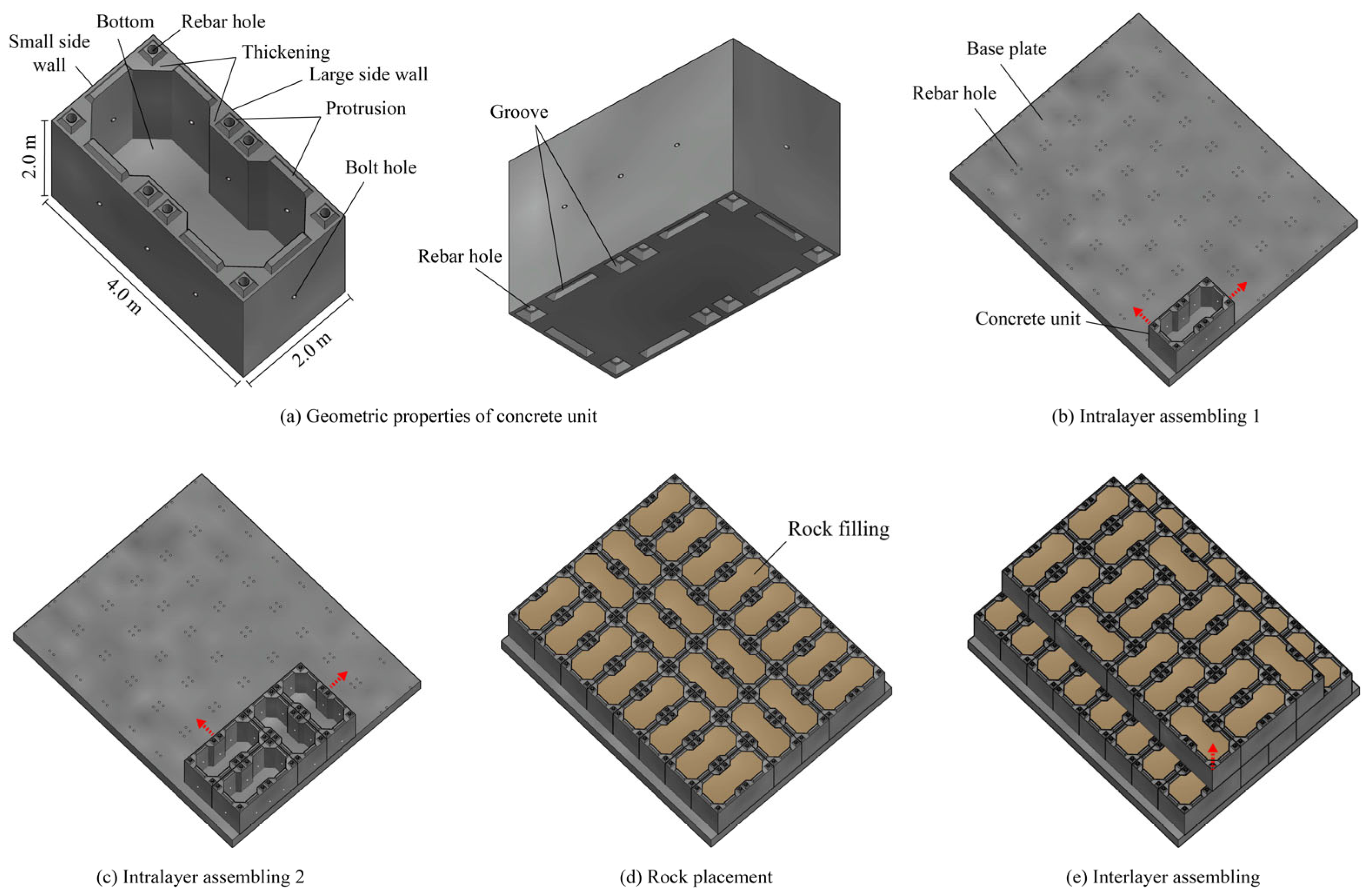
The schematic diagram of the above assembly process is shown in Figure 1.
Figure 1. Prefabricated reinforced guide wall structure and its assembly method.
Applsci 15 12083 g001

3. Methodology

To reasonably evaluate the structural performance, this paper uses a nonlinear contact model to describe the spatial contact mechanical behavior between concrete units, a metal plasticity model to characterize the possible plastic behavior of bolts and rebars, and combines FE analysis methods for stress, deformation, and stability to form a nonlinear numerical analysis method for the mechanical behavior of the guide wall.

3.1. Nonlinear Contact Model and Metal Plasticity Model

The prefabricated reinforced guide wall exhibits nonlinear contact behavior between concrete units, with complex spatial morphology of contact surfaces. When two surfaces come into contact and generate relative sliding or a tendency to slide, the contact surface transmits not only normal stress but also tangential friction forces along the contact surface, affecting the movement of concrete units and the stability of the wall [11]. The Coulomb model is often used to describe the interaction between contact surfaces, which employs the friction coefficient to characterize the frictional behavior between two surfaces [12,13]. In addition, the exponential model [14] for soft contact is the common model describing the normal behavior of contact surfaces. Therefore, the Coulomb model for tangential behavior and the exponential model for normal behavior are jointly employed in this study. A schematic of the adopted nonlinear contact model is shown in Figure 2 (Note: τcrit is the critical shear stress value, c0 and p0 are the initial contact distance and initial contact pressure, respectively).
When relative movement or a tendency for movement occurs between units within a layer or between layers, the bolts and reinforcement bars exhibit elastoplastic behavior. In particular, when the frictional resistance between standard units or between the base plate and the units is insufficient, or when the cross-sectional area of the reinforcement bars is relatively small, localized yielding of the reinforcement may occur, leading to evident elastoplastic behavior [15,16,17]. Considering the complexity of experimental stress–strain curves of metallic materials, a commonly used two-stage model is applied to represent the stress–strain relationship of bolts and rebars for numerical implementation [18,19,20].

3.2. Analysis Method of Structural Stress–Deformation–Stability

When employing a numerical simulation approach based on the FE method, the structure must first be discretized into FE meshes according to its geometry. Subsequently, interactions such as surface contact and embedding are introduced to connect the concrete units, bolts, reinforcement bars, and the concrete base plate, forming an integrated three-dimensional FE model of the guide wall [21,22,23]. In this study, all numerical simulations are conducted using ABAQUS 6.11, a widely recognized commercial finite element software capable of accurately modeling nonlinear contact behavior and material plasticity [24]. This software is particularly suitable for the multi-body contact and elastoplastic problems involved in the prefabricated reinforced guide wall, widely used in stress and deformation analysis of prefabricated structures [25,26,27].
For the guide wall described in this paper, its inter-layer stability can be judged by the slip amount of the inter-layer contact surface and whether the rebars yield. Within the FEM framework, this safety factor is typically calculated as the ratio of the algebraic sums of the resisting and driving stresses, which provides the foundation for the subsequent analysis of the mechanical performance and influencing factors of the prefabricated reinforced guide wall.

4. Analysis of the Performance and Its Influencing Factors of the Prefabricated Reinforced Guide Wall

4.1. Structural Geometry and Configuration

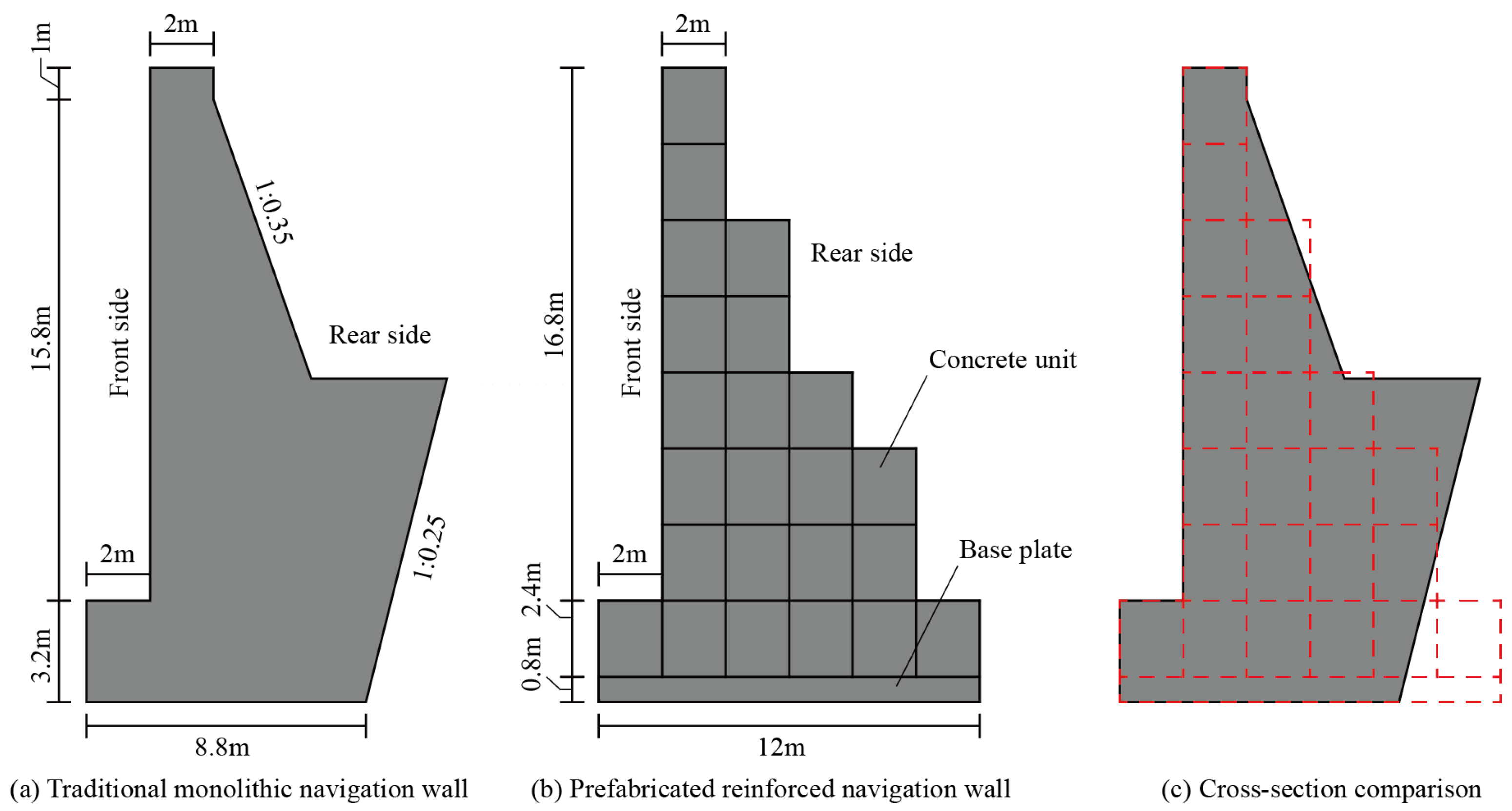
A representative engineering case located in a river reach with both shipping and hydropower functions is selected to evaluate the mechanical behavior of the proposed guide wall. As a key hydraulic structure, the guide wall ensures shipping safety and hydraulic stability during operation. According to the design specifications, the foundation elevation of the wall is 332.8 m. When constructed using the conventional monolithic structure, the cross-section fulfilling the structural requirements features: a top width of 2.0 m, a height of 20.0 m, a base width of 9.10 m, and back slope gradients of 1:0.35 and 1:0.25. The corresponding cross-section is illustrated in Figure 3a. Among them, there is backfill and water in front of and behind the wall, and the water level depends on the project’s operational conditions and shipping requirements. Table 1 presents four typical loading scenarios for the guide wall.
Based on the cross-section of the monolithic structure, the proposed prefabricated reinforced guide wall can be designed with a cross-section as shown in Figure 3b. Utilizing the assembly method described in Section 1, the lowest part of the wall is a 0.8 m-thick concrete base plate. Above this, layers 1 to 8 consist of standard precast concrete units: 12, 8, 8, 6, 4, 4, 2, and 2 units per layer, respectively. These eight layers incorporate a total of 56 connecting bolts. The corresponding assembly sequence is schematically depicted in Figure 4. To enhance inter-layer stability, longitudinal reinforcement bundles are placed through pre-formed rebar holes within the concrete units, connecting the layers to form an integrated structure. The simulated typical structural segment contains 96 such reinforcement bundles (each bundle comprising 3 rebars). As evident from Figure 3c, the precast units effectively replicate the cross-section of the traditional monolithic guide wall. The cross-sectional areas of the proposed prefabricated reinforced wall and the monolithic wall are 120.00 m2 and 121.92 m2, respectively. This indicates that the prefabricated reinforced guide wall can effectively fulfill the function of the monolithic wall while maintaining structural safety.
The main loads acting on the guide wall include hydrostatic pressure in front of and behind the wall, earth pressure (above and below water level) in front of and behind the wall, uplift pressure at the foundation, and self-weight. Among these, the self-weight is applied as a body force, whereas the hydrostatic pressure, earth pressure, and uplift pressure are applied as surface pressures. It should be noted that earth pressure is calculated separately for the portions above and below the water level, with the submerged earth pressure determined based on the saturated unit weight of the soil. In addition, the earth pressure on vertical wall surfaces is calculated using the Rankine theory, whereas for non-vertical wall surfaces, earth pressure is obtained based on the failure-surface theory [28,29]. Under these loads, stress concentrations may occur at specific critical points, potentially leading to local failure. Furthermore, founded on a silty sandstone foundation, the wall may experience global sliding relative to the foundation under load. For the prefabricated reinforced guide wall, in addition to concerns regarding local failure and global stability (base plate relative to foundation), it is essential to ensure inter-layer stability. This means stability must be maintained between the base plate and the bottommost units, as well as between successive upper layers of units.

4.2. Model and Parameters

According to the typical structural segment in Figure 4, the base plate, concrete units, bolts, and rebars were discretized into meshes to establish a three-dimensional FE model of the prefabricated reinforced guide wall for the mentioned project. The FE mesh of the concrete base plate includes 1377 nodes and 832 three-dimensional 8-node solid elements. Each concrete unit’s FE mesh contains 694 nodes and 328 three-dimensional 8-node solid elements. Common two-node truss elements were used to model bolts and rebars, forming 224 and 2400 truss elements, respectively, with their spatial layout shown in Figure 5a,b. The final three-dimensional FE model of the guide wall, illustrated in Figure 5c, comprises a total of 18,544 elements (combining solid and truss elements).
Contact interactions were defined between adjacent concrete units, between the bottommost units and the concrete base plate, and between the base plate and the foundation. Complex interactions between these components were simulated by establishing contact pairs and applying nonlinear contact models. The spatial configuration of the defined contact surfaces is presented in Figure 5d. Furthermore, bolts and reinforcement bars are embedded within the concrete units. Embedded region constraints were applied to model the interaction between the bolts/reinforcement and the surrounding concrete elements. The materials and computational parameters used in the FE analysis are summarized in Table 2.

4.3. Mechanical Behavior Analysis

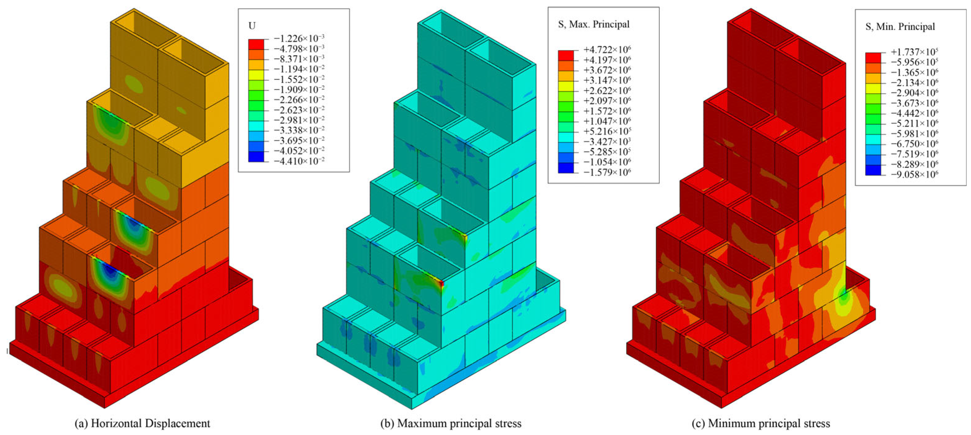
Taking typical condition 1 (high water level) from Table 1 as an example, an in-depth analysis of the mechanical performance of the prefabricated reinforced guide wall is conducted. The horizontal displacement contour of the guide wall is shown in Figure 6a, while the distributions of the maximum and minimum principal stresses are presented in Figure 6b and Figure 6c, respectively. As shown in Figure 6a, the guide wall exhibits a deformation pattern inclined toward the upstream (water-facing) side. This behavior is primarily attributed to the significantly higher elevation of the backfill behind the wall compared with the front side, resulting in a resultant active earth pressure acting toward the water side. The horizontal displacement gradually decreases from 11.49 mm at the top of the wall to 3.17 mm at the bottom, which is consistent with the typical cantilever deformation characteristics of gravity retaining structures, indicating a coordinated global deformation pattern. It is worth noting that the displacement at the top of the wall (11.49 mm) is slightly larger than that of the conventional monolithic wall (8.29 mm). This difference is mainly due to the prefabricated configuration, in which discrete concrete units are assembled, and then small, non-continuous deformations accumulate at the joints. However, the magnitude of displacement remains well within acceptable limits and does not affect the structural stability or service performance.
As seen in Figure 6b,c, the stress levels in the concrete units and the base plate are generally low, and the entire structure remains in a compressive state. This reflects the advantage of the working mechanism of the prefabricated guide wall, where the self-weight of the concrete units and internal rockfill effectively resists external loads. On the water-facing side, both the maximum and minimum principal stresses are compressive, ranging from −1.58 to −0.73 MPa and −9.06 to −0.63 MPa, respectively. Most regions on the land-facing side also experience compression, with only localized low tensile stresses of 0.25 to 0.50 MPa, far below the tensile strength of concrete, indicating that the concrete material remains safe. Compared with the traditional monolithic guide wall (maximum compressive stress of −0.39 MPa), the compressive stress levels of the prefabricated structure are slightly higher but still within the allowable strength range. The overall stress distribution is uniform, demonstrating the effectiveness of load transfer within the prefabricated system.
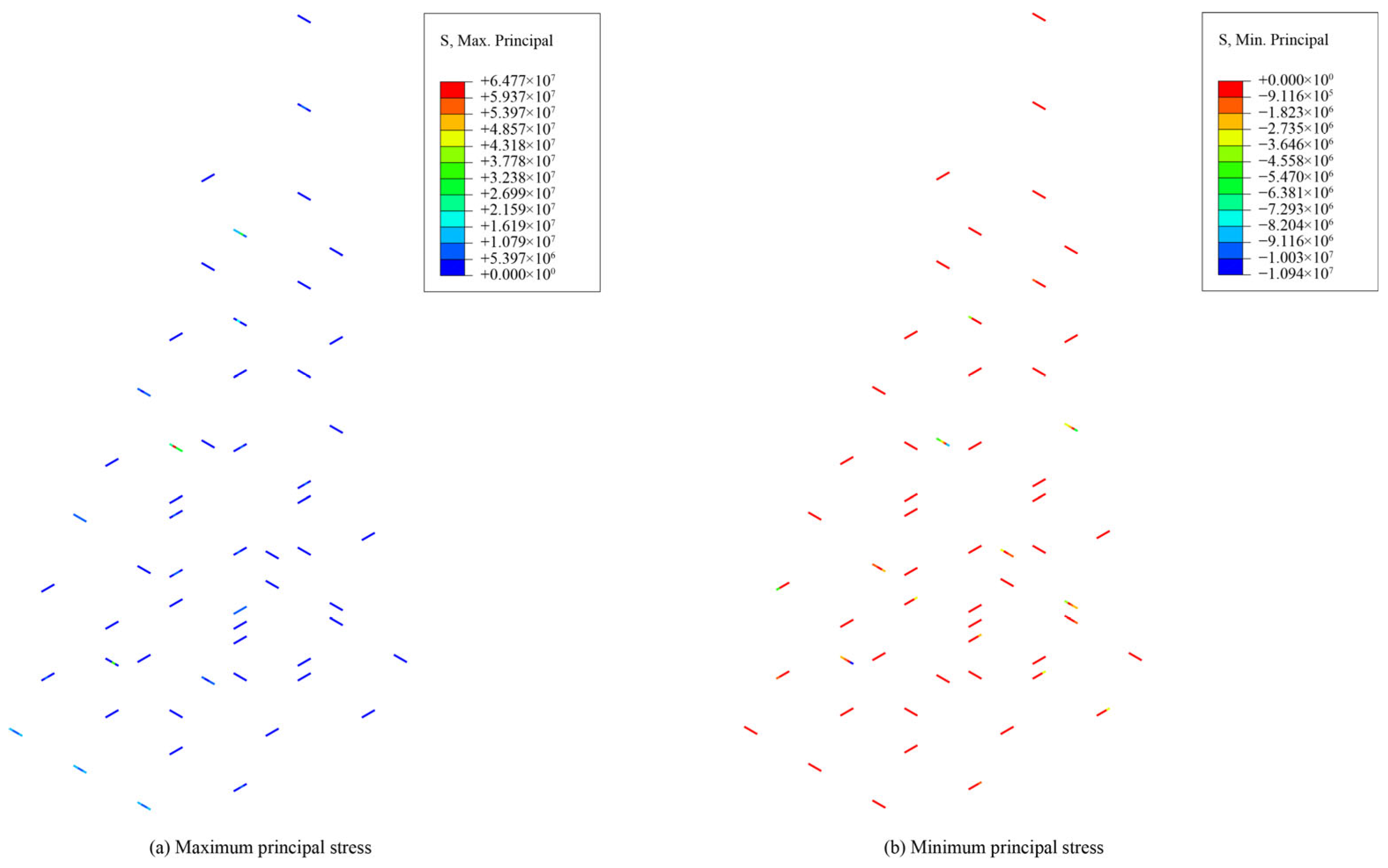
The mechanical behavior of the connectors is critical for evaluating the performance of the prefabricated structure. The stress levels of the bolts are generally low (mostly within 20 MPa, far below the yield strength of 320 MPa, as seen in Figure 7), indicating that their primary role in the current design is to ensure the integrity and cooperative action of units within the same layer rather than to carry major loads. All bolts remain in the linear elastic range, demonstrating reliable connections. In contrast, the stress response of the vertical reinforcement bars reveals the key mechanism governing inter-layer interaction.
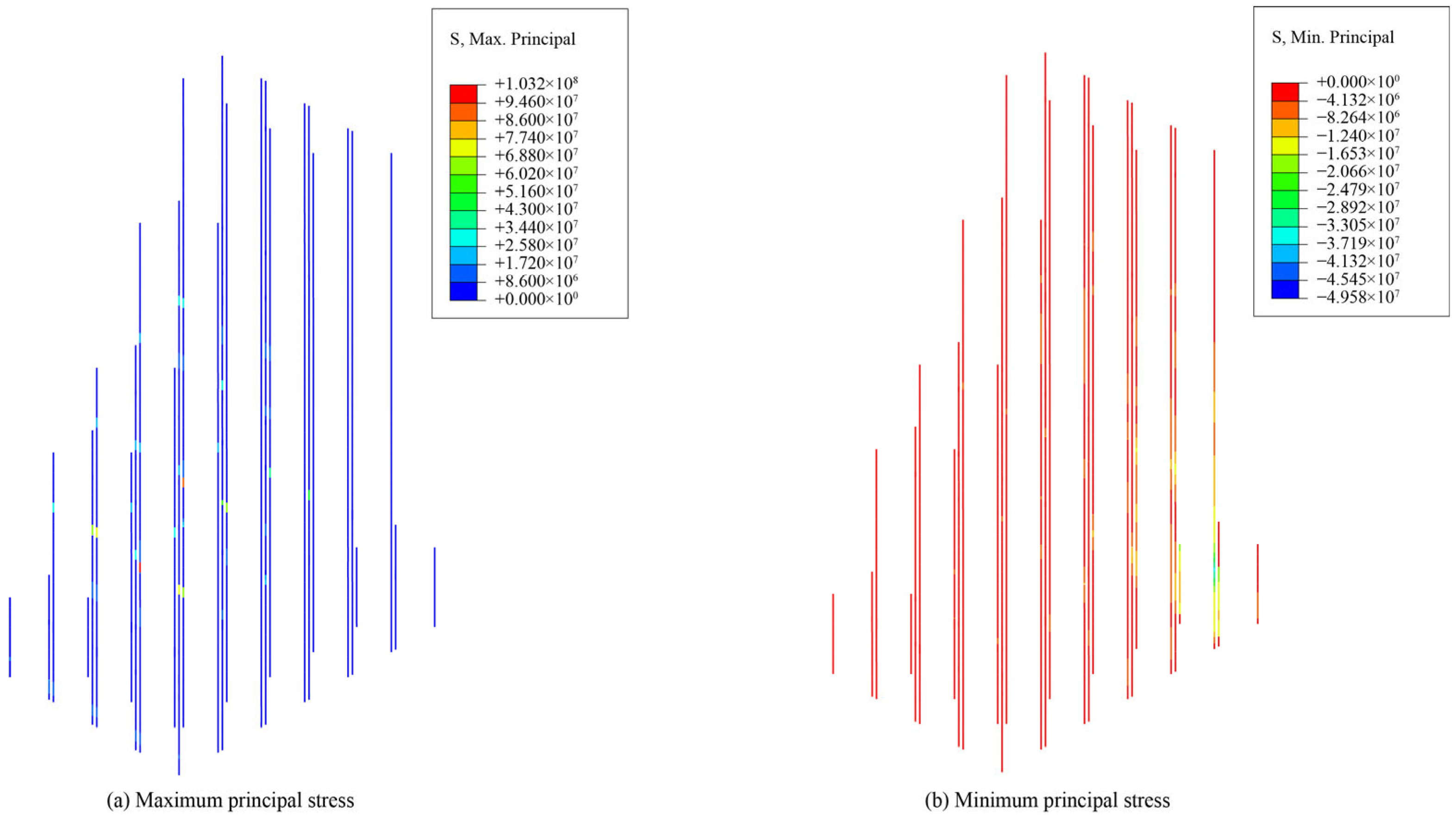
As shown in Figure 8, the noticeable stress concentrations occur between the 2nd–3rd layers and 3rd–4th layers on the land-facing side of the wall, with peak values reaching 103.24 MPa and 86.26 MPa, respectively. This indicates that these inter-layer contact interfaces act as critical shear planes resisting overall overturning and sliding of the structure. Under horizontal loading, relative sliding tends to occur between adjacent concrete units at these locations, while the vertical reinforcement bars effectively suppress such movement through their tensile and shear capacity, making it a core component for maintaining inter-layer stability. The current stress levels remain well below the yield strength of the reinforcement bars, and no plastic zones are observed, demonstrating the reliability of the design. Meanwhile, these observations also highlight the importance of paying particular attention to these critical regions in future design optimization. Finally, the analysis of inter-layer slip further verifies the effectiveness of the adopted nonlinear contact model. The slip between layers remains very small (0 to 1.06 mm), and the slip between the base plate and the foundation is 1.24 mm. This indicates that, under the combined action of the reinforcement bars and the self-weight of structures, the contact interfaces maintain continuous contact and structural stability throughout the loading process. These results confirm that the developed numerical model can accurately capture the complex spatial contact behavior and mechanical response of the prefabricated structure.
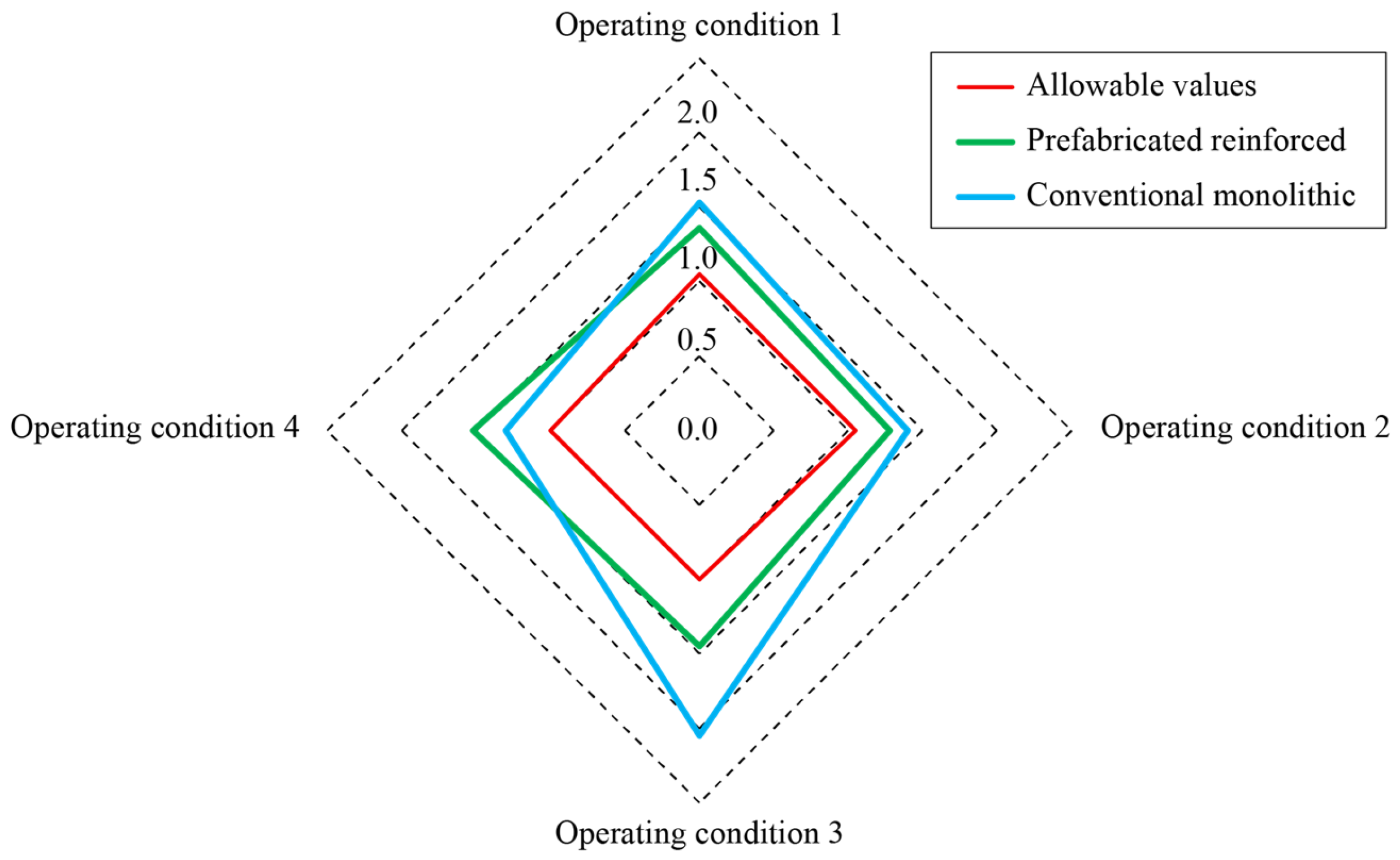
For typical operating conditions 2 to 4, fluctuations in the upstream and downstream water levels cause corresponding variations in the displacement and stress values of the prefabricated reinforced guide wall compared to condition 1. However, the overall deformation characteristics and stress distribution patterns remain similar to those under condition 1, with most regions staying in compression and only minor tensile stresses appearing locally, while the inter-layer stability is maintained. The stability safety factors for both the prefabricated and the monolithic wall under typical conditions are compared in Figure 9. The results indicate that the overall stability safety factors of the proposed prefabricated wall are comparable to those of the traditional monolithic wall and all exceed the required specification limits. This demonstrates that the prefabricated reinforced guide wall can maintain both inter-layer and global stability under different operating conditions. Furthermore, as rockfill is used as infill within the prefabricated units during assembly, the total concrete volume of the standard segment is significantly lower than that of the traditional monolithic guide wall, demonstrating advantages in efficient construction and environmental sustainability.
It should be noted that, compared with the traditional monolithic guide wall, the rear face of the prefabricated reinforced guide wall is simplified. This simplification is intentionally introduced to standardize the geometry of prefabricated concrete units and to facilitate modular assembly, transportation, and on-site installation. The simplification has no significant effect on the overall functional performance of the guide wall because the rear face mainly interfaces with the backfill and is not directly exposed to the flow field, while the front flow-guiding surface retains the same profile as the traditional structure. What’s more, the results further indicate that the safety factors of the prefabricated guide wall under several typical operating conditions meet the requirements, confirming that the simplified geometry does not compromise flow-guiding efficiency or structural stability.

4.4. Analysis of the Impact of Different Design Schemes

4.4.1. Influence of Bolt and Rebar Configurations

Bolts contribute to enhancing the integrity of the concrete units within each layer. Previous analyses indicated that under the 30 mm diameter bolt configuration, bolt stresses in all typical conditions remained well below the yield strength. To further quantify the influence of bolt configuration on the mechanical behavior of the guide wall, the following three comparative bolt configuration schemes are established:
Configuration ①: No bolts are installed between layers.
Configuration ②: Bolt installation method unchanged, diameter = 20 mm, yield strength = 320 MPa.
Configuration ③: Bolt installation method unchanged, diameter = 30 mm, yield strength = 320 MPa.
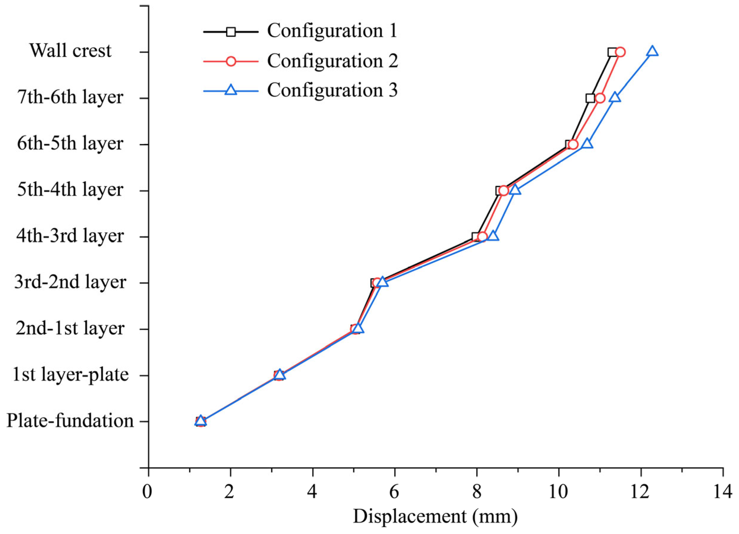
From the results of different bolt configuration schemes, bolts have little influence on the stress and deformation of the guide wall. Taking the most intuitive horizontal displacement as an example, the wall deforms toward the front of the wall under Configuration ① (without bolts). The horizontal displacement at the wall top is 11.36 mm, and the horizontal displacements of the concrete units from the 7th to 1st layers are 10.87 mm, 10.17 mm, 8.63 mm, 8.13 mm, 5.55 mm, 5.04 mm, and 3.16 mm, respectively. The horizontal displacement of the bottom concrete unit relative to the base plate is 1.26 mm. The displacement values are almost identical to those observed under Configuration ② and Configuration ③, indicating that the role of in-layer bolts is relatively limited. The stability of the prefabricated reinforced guide wall is controlled by the self-weight of the wall and the shear resistance of the longitudinal rebars.
To further quantify the influence of rebar configuration on the mechanical behavior of the wall, the following four comparative reinforcement configuration schemes are compared:
Configuration ①: Rebar installation method unchanged, diameter = 32 mm, yield strength = 300 MPa.
Configuration ②: Rebar installation method unchanged, diameter = 28 mm, yield strength = 300 MPa.
Configuration ③: Rebar installation method unchanged, diameter = 25 mm, yield strength = 300 MPa.
Configuration ④: Rebar installation method unchanged, diameter = 22 mm, yield strength = 300 MPa.
A comparison of horizontal displacements for guide walls under Configurations ① to ③ is shown in Figure 10. For Configuration ④, it should be noted that due to insufficient diameter, excessive plastic deformation occurs under shear action, which further leads to excessive sliding of the interlayer standard components, ultimately resulting in interlayer instability and failing to converge. If only the linear elastic model is used, although the stress has exceeded the yield strength, the resulting elastic deformation is significantly lower than the plastic deformation, which may lead to a misjudgment of the overall stability of the wall. This implies that for precast units with embedded reinforcement, longitudinal reinforcement with a diameter not less than 25 mm and a yield strength not less than 300 MPa is required to maintain inter-layer stability.
Results from Configurations ① to ③ demonstrate that increasing the reinforcement diameter has a significant effect on the guide wall’s mechanical behavior. For instance, the horizontal displacement at the wall top under Configuration ① (32 mm diameter, 300 MPa yield strength) is 11.30 mm, which is lower than the 11.49 mm under Configuration ② and the 12.28 mm under Configuration ③.
The locations of high-stress zones in the rebar did not change across different reinforcement diameters and yield strengths; they consistently occurred at the interfaces between the 2nd and 3rd concrete layers, and between the 3rd and 4th concrete layers. This indicates that for the project utilizing the prefabricated reinforced guide wall, the inter-layer stability between layers 2–3 and layers 3–4 requires particular attention.

4.4.2. Influence of Contact Surface Friction Coefficient

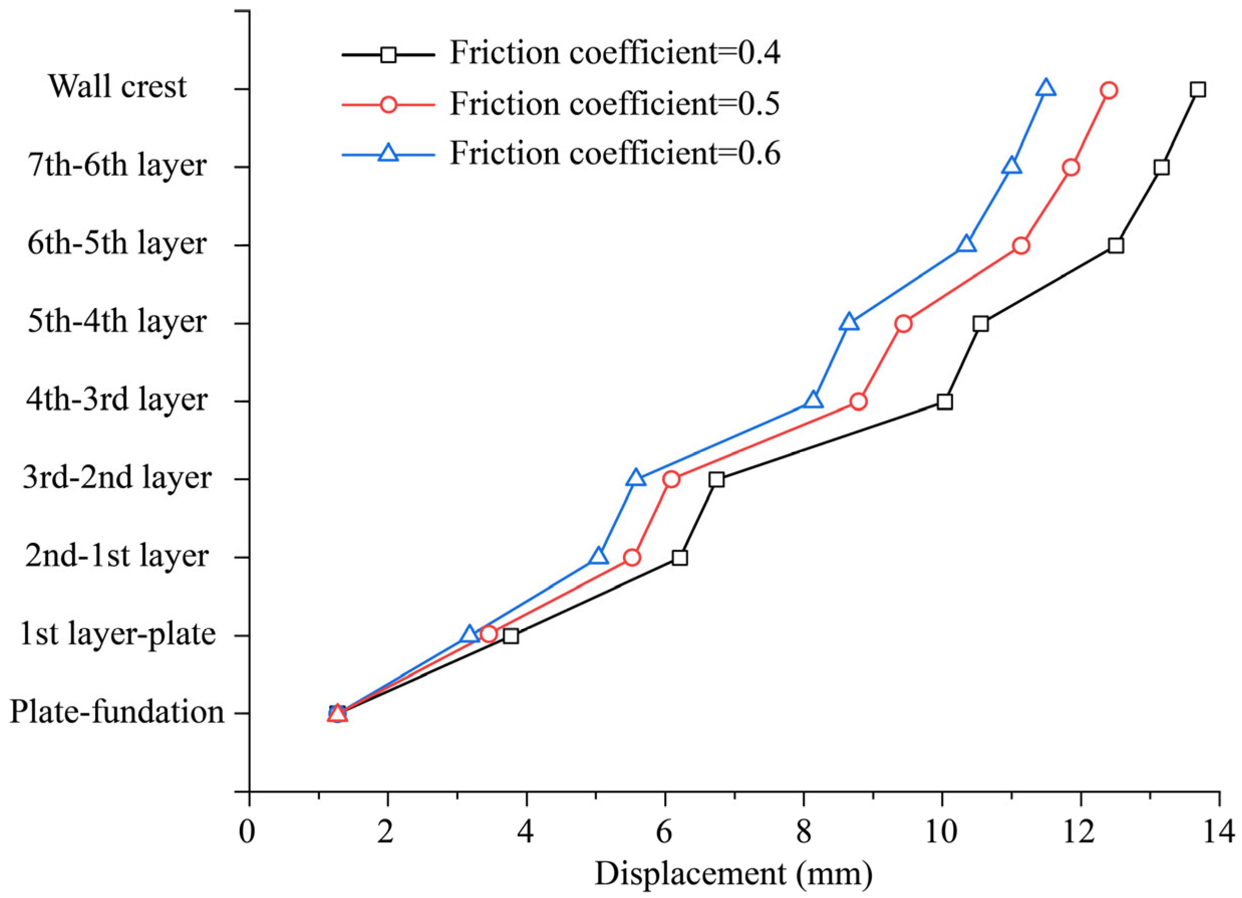
Three comparison cases of friction coefficients for concrete unit contact surfaces are set up here: Case ① with the friction coefficient reduced to 0.4, Case ② with the friction coefficient reduced to 0.5, and Case ③ with the friction coefficient taken as 0.6. The horizontal displacements of the guide wall under the three friction coefficients are shown in Figure 11.
Taking Case ① (friction coefficient 0.4) as an example, the horizontal displacement at the wall top is 13.69 mm, and the horizontal displacements of the units from the 7th to 1st layers are 13.17 mm, 12.51 mm, 10.55 mm, 10.04 mm, 6.74 mm, 6.21 mm, and 3.78 mm, respectively. The horizontal displacement of the bottom concrete unit relative to the base plate is 1.27 mm, which is overall higher than that in Case ② (wall top horizontal displacement of 12.41 mm) and Case ③ (wall top horizontal displacement of 11.49 mm). The results show that when the contact surface friction coefficient decreases, although the guide wall can maintain inter-layer stability under the action of rebars and self-weight, the weakening of shear resistance leads to a significant increase in wall displacement. The high-stress regions of rebars under different friction coefficients do not change, all located between the 2nd and 3rd layers and the 3rd and 4th layers of concrete units. In addition, after the friction coefficient decreases, the shear effect on rebars is further enhanced, and the stress values of rebars increase to a certain extent. For example, when the friction coefficient between units decreases from 0.6 to 0.5 and 0.4, the maximum principal stress of rebars increases from 204.11 MPa to 207.39 MPa and 211.88 MPa, respectively. However, the increased stress values are still within the yield strength of rebars, and the guide wall remains in a stable state.

4.4.3. Discussion on Bottomless Concrete Units

Previous analyses demonstrated that the prefabricated reinforced guide wall, incorporating waste rock fill within the concrete units and configured with appropriate longitudinal reinforcement bundles, can maintain both inter-layer and global stability under the action of water pressure, self-weight, and earth pressure. In such a configuration, the primary role of the rockfill is to increase the overall self-weight of the wall to enhance stability. Due to settlement or construction disturbance, the lower-layer rockfill may easily separate from the underside of the upper concrete unit, and the friction between the rockfill and the base slab is not explicitly considered. To simplify the concrete unit structure for standardized production, this section explores the feasibility of forming a guide wall using bottomless concrete units. In this configuration, each concrete module retains only the surrounding sidewalls, and waste rockfill is placed inside each layer during assembly. In addition to friction between adjacent concrete units, the interlayer rockfill also contributes to shear resistance through its integrated behavior across layers. Therefore, a preliminary study is conducted to examine whether a prefabricated guide wall can be formed using bottomless units without longitudinal reinforcement bars. Here, an equivalent inter-layer friction coefficient is introduced to represent the combined shear-transfer capacity resulting from (a) contact friction between the top surface of a lower unit and the bottom surface of an upper unit, and (b) the shear resistance provided by the interlayer rockfill. This modeling strategy is adopted because the mechanical interaction between rockfill and concrete units, as well as the interaction among rockfill layers, is highly complex, making continuum-based numerical modeling extremely difficult. Considering that rockfill typically exhibits negligible cohesion and primarily mobilizes frictional resistance, an area-weighted equivalent friction coefficient can theoretically capture the inter-layer shear contribution of the bottomless concrete units. Therefore, the equivalent friction coefficient fe is calculated using the area-weighted method:
f e = f c A c + f r A r / A c + A r
where fc is the friction coefficient between the concrete at the bottom of the upper unit and the top of the lower unit; Ac is the area of the concrete-to-concrete contact surface; fr is the friction coefficient of the rockfill (related to its friction angle φ, typically fr = tanφ); Ar is the cross-sectional area of the rockfill between the upper and lower units.
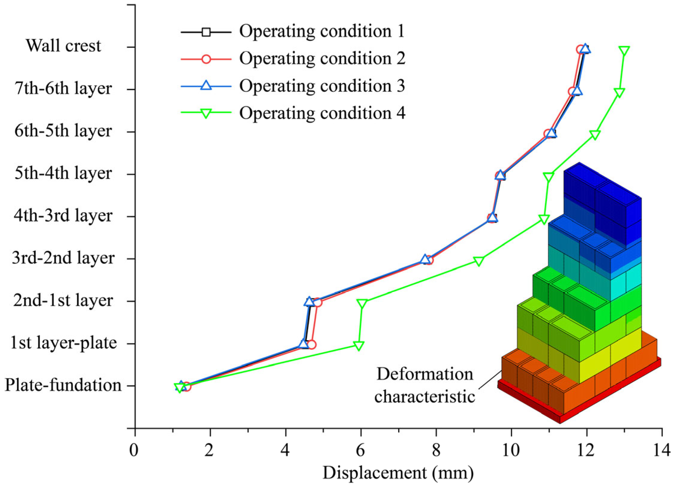
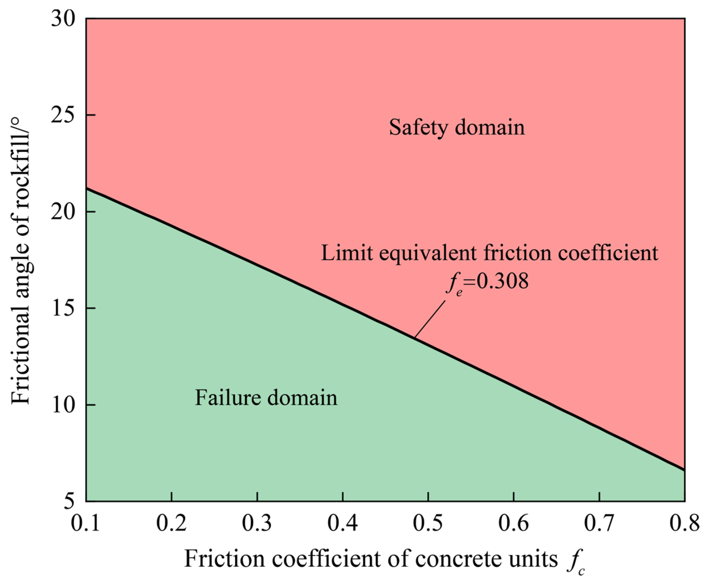
Based on the four typical operating conditions listed in Table 1, the binary search method was employed to determine the critical equivalent friction coefficient for inter-layer stability under each condition. Taking condition 1 as an example, the search revealed a critical equivalent inter-layer friction coefficient of 0.306. At this state, the guide wall displacements lean towards the front side of the wall. The horizontal displacement at the wall top is 11.82 mm. The horizontal displacements from layer 7 down to layer 1 of the units are 11.58 mm, 10.95 mm, 9.60 mm, 9.37 mm, 7.64 mm, 4.52 mm, and 4.37 mm, respectively. The horizontal displacement of the bottommost units relative to the base plate is 1.13 mm. This implies that any further reduction in the unit–unit friction coefficient or the rockfill friction angle would lead to inter-layer instability. To identify the controlling equivalent friction coefficient across all conditions, the binary search method was continued for conditions 2, 3, and 4, yielding critical equivalent friction coefficients of 0.308, 0.285, and 0.283, respectively. The corresponding limiting deformations and distribution characteristics for all four conditions are shown in Figure 12. The results indicate that condition 2 imposes the highest demand on the equivalent friction coefficient (0.308), making it the controlling condition for inter-layer stability in the bottomless unit scheme. Combining Equation (1), the feasible region for the rockfill friction angle φ and the unit–unit friction coefficient fc can be defined, as illustrated in Figure 13. That is, when the combination of φ and fc lies above the line in Figure 13, the prefabricated guide wall formed by bottomless concrete units without reinforcement bundles can maintain inter-layer stability under different operating conditions. Otherwise, inter-layer instability will occur in the prefabricated guide wall. This feasible region can provide references for applying the proposed prefabricated guide wall concept in other similar projects.

5. Future Work

In this study, the deformation, stress response, and stability performance of the prefabricated guide wall have been investigated and compared with those of the traditional monolithic guide wall under typical operating conditions. However, the cracking behavior of guide wall structures under more complex service conditions (e.g., temperature stress, ship collision, and ice floe impact) still requires further investigation. Future research will perform comparative studies between prefabricated and monolithic systems to evaluate their crack-resistance performance, damage evolution, and energy-dissipation capacity under such extreme environments using the nonlinear concrete constitutive models and cracking/damage mechanisms, thereby extending the applicability of the proposed system to demanding navigation conditions.
Although this study establishes a sophisticated nonlinear finite-element model and provides detailed insights into inter-layer slip, reinforcement bars behavior, and contact response, the current findings rely solely on numerical simulations. Future research will conduct the scaled physical models to validate the FE analysis results. The experimental data will help us further calibrate parameters of FE analysis, optimize relevant details, and enhance the accuracy, reliability, and engineering applicability of the proposed prefabricated navigation wall design framework.

6. Conclusions

Conventional construction of guide walls faces multiple challenges, including complicated construction, high cement consumption, cracking risks, and limited adaptability, which hinder their application in mountainous river locks. To address these problems, this study proposes a novel prefabricated reinforced guide wall, composed of a concrete base plate, prefabricated units, intra-layer bolts, and inter-layer reinforcement bars. A nonlinear numerical framework, integrating contact mechanics, metal plasticity, and finite element analysis, is established to simulate the mechanical behavior under hydraulic and impact loads, enabling a comprehensive assessment of stress, deformation, and inter-layer stability.
Numerical analysis results demonstrate that the prefabricated reinforced guide wall exhibits safe stress distribution, stable deformation, and reliable inter-layer stability. Owing to the hollow prefabricated configuration that replaces a portion of the concrete with rockfill, the proposed system effectively reduces cement usage and supports low-carbon and sustainable development. These findings confirm the feasibility and advantages of the proposed design, providing theoretical insights and engineering references for the sustainable application of prefabricated reinforced guide walls in mountainous river locks.

Author Contributions

Conceptualization, L.W. and Y.L.; Methodology, L.W. and Y.L., X.L. and Z.W.; Formal analysis, Y.L. and X.L.; Writing—original draft, L.W.; Writing—review & editing, Y.L.; Project administration, Y.L. and Z.W.; Funding acquisition, X.L. All authors have read and agreed to the published version of the manuscript.

Funding

This research was supported by the Supported by The Sichuan Communication Surveying & Design institute Co., Ltd. (232022017), the Natural Science Foundation of Sichuan Province (2025ZNSFSC0414) and the National Natural Science Foundation of China (No. 52309162).

Institutional Review Board Statement

Not applicable.

Informed Consent Statement

Not applicable.

Data Availability Statement

The raw data supporting the conclusions of this article will be made available by the authors on request.

Acknowledgments

Thank you Yanling Li for her guidance during the project research and paper writing process.

Conflicts of Interest

Authors Liguo Wu and Yonglong Li were employed by the company Sichuan Communication Surveying Design Institute Co., Ltd. The remaining authors declare that the research was conducted in the absence of any commercial or financial relationships that could be construed as a potential conflict of interest.

References

  1. Hulagabali, A.; Solanki, C.; Dodagoudar, G.; Anitha. Finite Element Analysis of Segmental Precast Concrete Panel Reinforced Earth Retaining Wall. Jordan J. Civ. Eng. 2023, 17, 582–597. [Google Scholar] [CrossRef]
  2. Ferdous, W.; Bai, Y.; Almutairi, A.D.; Satasivam, S.; Jeske, J. Modular Assembly of Water-Retaining Walls Using GFRP Hollow Profiles: Components and Connection Performance. Compos. Struct. 2018, 194, 1–11. [Google Scholar] [CrossRef]
  3. Yu, X.; Cheng, J. Prefabricated Reinforced Concrete Wall Protection. In Lecture Notes in Civil Engineering, Proceedings of the 2nd International Conference on Advanced Civil Engineering and Smart Structures, Chengdu, China, 25–26 November 2023; Springer: Singapore, 2024; pp. 303–308. [Google Scholar]
  4. Zhao, J.; Liu, R.; Zhou, B.; Fu, Y.; Li, Y.; Zhang, W. Thermal performance and passive energy saving optimization of prefabricated houses in Xinjiang region. Case Stud. Therm. Eng. 2025, 70, 106082. [Google Scholar] [CrossRef]
  5. Yang, X.; Huang, M.; Peng, Z.; Lin, F. Calculation of dynamic assembly and tensioning loads at multiple points of prefabricated structure. Tunn. Undergr. Space Technol. 2022, 126, 104564. [Google Scholar] [CrossRef]
  6. Yang, X.; Lin, F. Research on prefabricated metro station structure and key assembly technologies. Tunn. Undergr. Space Technol. 2024, 153, 106029. [Google Scholar] [CrossRef]
  7. Ma, S.; Li, Z.; Fu, R. A Fully Prefabricated Pile-Wall Composite Scheme of Open-Cut Tunnel and the Mechanical Behavior of the Composite Structure during Construction. Buildings 2024, 14, 1693. [Google Scholar] [CrossRef]
  8. Chen, L.; Xie, H.; Xiang, N.; Zhang, K.; Yang, S.; Hu, Z. Optimized evaluation of ground motion intensity measures for the prefabricated cantilevered roadbed structure in mountainous areas. Structures 2024, 70, 107701. [Google Scholar] [CrossRef]
  9. Huang, Z.; Yang, Y. Vibration Response Characteristics of Prefabricated Frame Structures Around the Subway. Appl. Sci. 2025, 15, 6419. [Google Scholar] [CrossRef]
  10. Wang, X.; Zhu, C.; Diao, H.; Ning, Y. Structural Behavior of Prefabricated Ecological Grid Retaining Walls and Application in a Highway in China. Symmetry 2021, 13, 746. [Google Scholar] [CrossRef]
  11. Wang, Z.; Hu, C. Examining Pipe-Borehole Wall Contact and Pullback Loads for Horizontal Directional Drilling. Appl. Sci. 2024, 14, 8841. [Google Scholar] [CrossRef]
  12. Borekci, M. Influence of Friction Models on the Seismic Response of Box-Girder RC Bridges with Double Concave Friction Pendulum Bearings under Varying Deck Aspect and Mass Ratios. Buildings 2025, 15, 556. [Google Scholar] [CrossRef]
  13. Fan, X.; Wang, T. Formulation and Implementation of a Hypoplastic Constitutive Model for Interface Behavior of Mechanical Joints. Mech. Syst. Signal Process. 2023, 204, 110735. [Google Scholar] [CrossRef]
  14. Wang, G.; Wang, Y.; Lu, W.; Yu, M.; Wang, C. Deterministic 3D Seismic Damage Analysis of Guandi Concrete Gravity Dam: A Case Study. Eng. Struct. 2017, 148, 263–276. [Google Scholar] [CrossRef]
  15. Zhang, A.; Ma, L.; Liu, X.; Jiang, Z. Finite Element Analysis on Mechanical Performance of Steel Frame Structure with Prefabricated External Wall Panel. J. Build. Struct. 2016, 37, 152–157. [Google Scholar] [CrossRef]
  16. Li, W.; Jing, Y.; Xing, G.; Ma, Z. A Lode-Dependent Plasticity Model for High-Strength Structural Steel. J. Constr. Steel Res. 2023, 211, 108202. [Google Scholar] [CrossRef]
  17. Mohsenali, S.; Pouria, Z.; Parsa Jelokhani, N.; Eskandari, A. Force-Displacement Relation for Lumped Plasticity Model of Compact Square Concrete-Filled Steel Tube Columns. Results Eng. 2024, 23, 102619. [Google Scholar]
  18. Moallemi, M.; Kim, S.; Abbas, Z.; Farabi, E. Strain Hardening Analysis and Deformation Micromechanisms in High Strength-High Ductility Metastable Duplex Stainless Steels: Role of Sustained Stacking Faults in the Work Hardening. Mater. Charact. 2023, 197, 112662. [Google Scholar] [CrossRef]
  19. Syroka-Korol, E.; Tejchman, J.; Mróz, Z. FE Analysis of Size Effects in Reinforced Concrete Beams without Shear Reinforcement Based on Stochastic Elasto-Plasticity with Non-Local Softening. Finite Elem. Anal. Des. 2014, 88, 25–41. [Google Scholar] [CrossRef]
  20. Li, S.; Ding, W.; Zhang, Q. Development of a New Temperature-Dependent Yield Criterion for Stainless and High-Strength Alloy Steels in Construction Engineering. Case Stud. Constr. Mater. 2023, 18, e02149. [Google Scholar] [CrossRef]
  21. Koksal, H.; Doran, B.; Kuruscu, A.; Kocak, A. Elastoplastic Finite Element Analysis of Masonry Shear Walls. KSCE J. Civ. Eng. 2015, 20, 784–791. [Google Scholar] [CrossRef]
  22. Keawsawasvong, S.; Ukritchon, B. Finite Element Analysis of Undrained Stability of Cantilever Flood Walls. Int. J. Geotech. Eng. 2016, 11, 355–367. [Google Scholar] [CrossRef]
  23. Li, Z.; Wu, Z.; Chen, J.; Li, Y.; Huang, H.; Lu, Y.; Lu, X.; Li, J. Inverse Analysis of Deformation Moduli for High Arch Dams Using the Displacement Reconstruction Technique and Multi-Objective Optimization. Comput. Aided Civ. Infrastruct. Eng. 2023, 39, 1507–1529. [Google Scholar] [CrossRef]
  24. Xue, J.; Zhang, P.; Li, J.; Lu, X.; Li, Z.; Li, Y.; Chen, J.; Kuang, C. A deep learning methodology for rapid identification of slab damage in concrete face rockfill dams. Comput. Aided Civ. Infrastruct. Eng. 2025, online. [Google Scholar] [CrossRef]
  25. Lu, Z.; Fan, Q.; Tian, W.; Li, J. Seismic Performance Analysis of Steel Frame Installed with Prefabricated External Walls and New Connection Type. J. Build. Eng. 2024, 84, 108471. [Google Scholar] [CrossRef]
  26. Liu, J.; Bao, Y.; Qin, K. Experimental and Finite Element Analysis on the Structural Performance of Lightweight Hollow Slab Prefabricated Staircases. Buildings 2025, 15, 245. [Google Scholar] [CrossRef]
  27. Zhang, L.; Liu, G.; Liu, G.; Xin, H.; Cai, J.; Satyanaga, A.; Zhang, R.; Dai, G. Seismic Behavior of Cluster-Connected Prefabricated Shear Walls under Different Axial Compression Ratios. Buildings 2024, 14, 2768. [Google Scholar] [CrossRef]
  28. Greco, V. Active thrust on retaining walls of narrow backfill width. Comput. Geotech. 2013, 50, 66–78. [Google Scholar] [CrossRef]
  29. Shi, H.; Gong, J.; Zhang, Y. Earth pressure of layered soil on retaining structures. Soil Dyn. Earthq. Eng. 2016, 83, 33–52. [Google Scholar] [CrossRef]
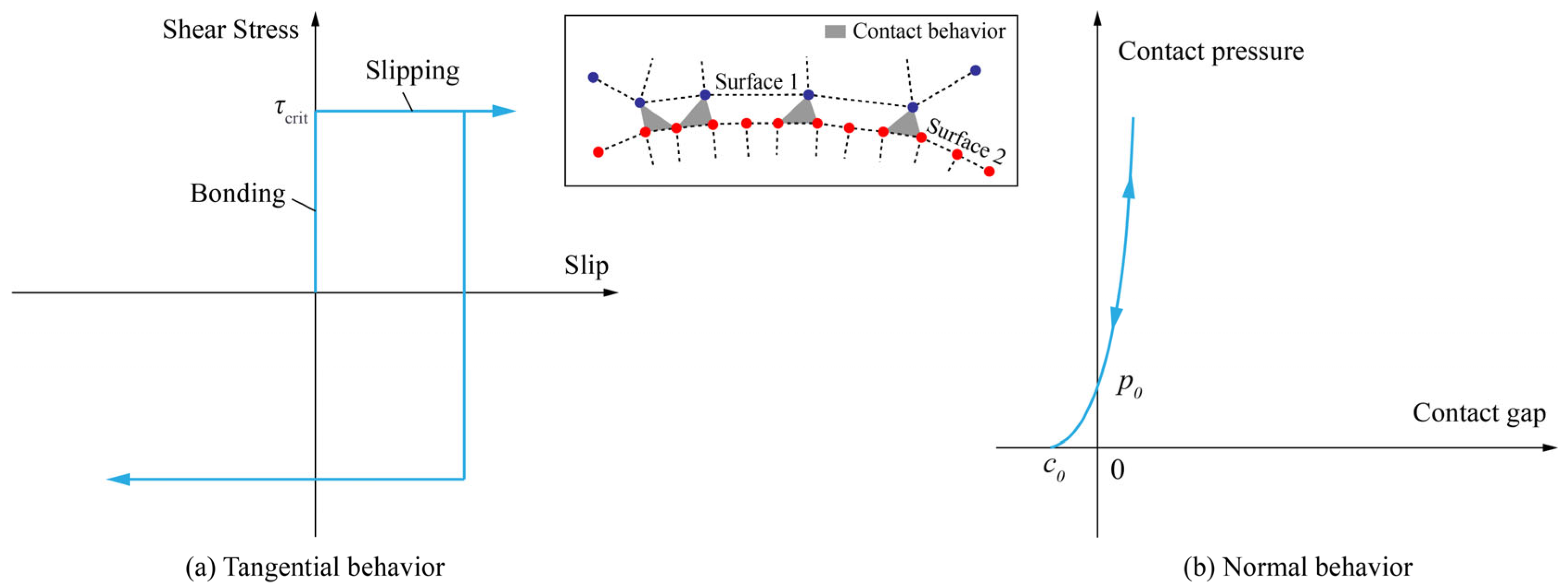
Figure 2. Nonlinear contact model for prefabricated reinforced guide wall.
Applsci 15 12083 g002
Figure 3. The cross-section of the traditional monolithic and prefabricated reinforced guide wall. (Note: The red dashed line in (c) is a virtual representation of (b) overlaid on (a)).
Applsci 15 12083 g003
Figure 4. The assembly process of the prefabricated reinforced guide wall.
Applsci 15 12083 g004
Figure 5. Finite element model of the prefabricated reinforced guide wall.
Applsci 15 12083 g005
Figure 6. Stress and deformation characteristics of the wall under typical operating condition 1.
Applsci 15 12083 g006
Figure 7. The maximum and minimum principal stresses of the bolt under typical operating condition 1.
Applsci 15 12083 g007
Figure 8. The maximum and minimum principal stresses of the rebars under typical operating condition 1.
Applsci 15 12083 g008
Figure 9. The global stability safety factors of prefabricated and monolithic guide walls under four typical operating conditions.
Applsci 15 12083 g009
Figure 10. Displacement of the guide wall under different rebar configurations in operating condition 1.
Applsci 15 12083 g010
Figure 11. Displacement of the guide wall under different concrete unit friction coefficients in operating condition 1.
Applsci 15 12083 g011
Figure 12. The limiting deformation of the guide wall under four operating conditions with bottomless concrete units.
Applsci 15 12083 g012
Figure 13. Feasible regions of fc and φ under bottomless concrete units.
Applsci 15 12083 g013
Table 1. Typical operating conditions of the project.
ConditionScenarioWater Level (Front)/mWater Level
(Behind)/m
Backfill Elevation (Front)/mBackfill Elevation (Behind)/m
1High water level346.44346.94338.00350.00
2Low water level340.5342.5338.00350.00
3Final Constructed//338.00350.00
4Check water level353.99353.99338.00350.00
Table 2. Finite element model parameters of the prefabricated reinforced guide wall.
NumberMaterial or Contact SurfaceParameterValue
1Concrete unitElastic modulus (GPa)30
Density (kg/m3)2380
Poisson’s ratio0.167
Tensile strength (MPa)2.2
Compressive strength (MPa)23.4
2Concrete base plateElastic modulus (GPa)28
Density (kg/m3)2380
Poisson’s ratio0.167
Tensile strength (MPa)1.78
Compressive strength (MPa)16.7
3Bolts and rebarsElastic modulus (GPa)210
Density (kg/m3)7850
Poisson’s ratio0.258
Yield strength (MPa)320 (Bolts)/300 (Rebars)
4RockfillDensity (kg/m3)7850
Friction angle (°)2000
5Unit–unitFriction coefficient0.6
6Unit–plateFriction coefficient0.6
7Plate–foundationFriction coefficient0.4
Disclaimer/Publisher’s Note: The statements, opinions and data contained in all publications are solely those of the individual author(s) and contributor(s) and not of MDPI and/or the editor(s). MDPI and/or the editor(s) disclaim responsibility for any injury to people or property resulting from any ideas, methods, instructions or products referred to in the content.