You are currently viewing a new version of our website. To view the old version click .
Applied Sciences
  • Article
  • Open Access

12 November 2025

Design and Experimental Validation of a Unidirectional Cable-Driven Exoskeleton for Upper Limb Rehabilitation

,
,
,
,
,
,
,
and
DIMEG—Department of Mechanical, Energy and Management Engineering, University of Calabria, 87036 Rende, Italy
*
Author to whom correspondence should be addressed.
This article belongs to the Special Issue Recent Developments in Exoskeletons

Abstract

Upper limb disabilities resulting from stroke affect millions worldwide, yet current rehabilitation systems face limitations in portability, cost-effectiveness, and multi-joint integration. This study presents a cable-driven parallel exoskeleton integrating elbow, wrist, and finger assistance into a single portable device. The design strategically separates actuation components, housing all motors in a backpack unit, while limb-mounted modules serve as cable routing guides, achieving seven degrees of freedom within practical constraints of portability (1.2–1.5 kg) and cost-effectiveness (3D-printed components). The device incorporates seven servo motors controlled via Arduino with IMU feedback and PID algorithms. Kinematic and dynamic analyses informed mechanical design, while ARMAX system identification enabled controller optimization achieving 87.96% model fit. Experimental validation with eight healthy participants performing four upper limb exercises demonstrated consistent trends toward reduced activation in four monitored agonist muscles with exoskeleton assistance (21.3% average reduction, p = 0.087), with moderate effect sizes for proximal muscles (Cohen’s d = 0.70–0.79) and significant reductions in brachioradialis during radial/ulnar deviation (23.4%, p = 0.045). These findings provide preliminary evidence of the device’s potential to reduce muscular effort during assisted movements, warranting further clinical validation with patient populations.

1. Introduction

Upper limb disabilities significantly impact the quality of life of millions worldwide, with stroke being a primary cause of long-term motor impairments affecting approximately 80% of survivors [,]. The complex biomechanics of the upper limb, encompassing multiple degrees of freedom from shoulder to fingers, present substantial rehabilitation challenges [,,]. Traditional manual therapy faces limitations including therapist availability, inconsistent delivery, and high costs, particularly amid an aging population and increasing stroke incidence [,]. Robotic rehabilitation systems have transformed upper limb recovery by providing intensive, consistent, and standardized therapeutic interventions [,], with neurophysiological studies demonstrating measurable impacts on motor system reorganization and functional recovery [].
Exoskeletons enable direct human–limb interaction while supporting natural movement patterns, with robot-assisted therapy demonstrating effectiveness comparable to or exceeding conventional therapy in functional outcomes [,,]. The development of effective rehabilitation exoskeletons requires systematic integration of biomechanical analysis [,], mechatronic design principles [], and intelligent control strategies [,,].
Cable-driven parallel robots (CDPRs) offer unique rehabilitation advantages, including simplified assembly, reconfigurability, light weight, and large workspaces [,]. Benefits include reduced inertia, high workspace-to-footprint ratios, and improved safety due to cable forces [,]. Recent developments include reconfigurable planar CDPRs [], variable stiffness actuation facilitating natural interaction through impedance control [], and robust control strategies ensuring safety during cable failure []. While these CDPR characteristics provide theoretical advantages for rehabilitation, translating them into practical, accessible devices for upper limb therapy remains challenging [].
Despite these advances, widespread adoption of robotic rehabilitation is limited by high costs, low portability, and the complexity of integrating multiple joints [,]. A significant gap remains in aiding multiple upper limb joints (elbow, wrist, fingers) within a single device that is simultaneously portable, cost-effective, and sufficiently capable of meaningful therapy. Existing systems address this challenge through three main approaches: (1) end-effector devices, which provide task-oriented training but lack joint-specific control; (2) rigid exoskeletons, offering precise joint control but often heavy (2–5 kg for multi-joint systems) due to motors distributed across joints [,,]; and (3) cable-driven systems, focusing on single joint complexes to manage mechanical and control complexity [,,]. Each approach involves trade-offs between comprehensiveness, portability, and accessibility, limiting clinical translation and home use, where device weight, ease of donning/doffing, cost, and user acceptance are critical factors [,].
This study addresses these gaps by presenting the design, development, and validation of a cable-driven parallel exoskeleton that integrates elbow, wrist, and finger rehabilitation into a single portable platform. The fundamental challenge lies in aiding multiple joint complexes spanning the upper limb while maintaining portability, cost-effectiveness, and ease of use necessary for widespread clinical adoption and home-based therapy. Our work addresses this challenge through systematic design decisions informed by biomechanical analysis, dynamic modeling, and practical rehabilitation constraints. The proposed system provides coordinated assistance across seven degrees of freedom through an integrated multi-joint architecture. Unlike previous approaches that either focus on single joints [,] or distribute motors along the kinematic chain [,], the design consolidates all actuation in a backpack unit, minimizing limb-mounted inertia to 80–150 g per module while maintaining comprehensive rehabilitation capability.
Dynamic simulations incorporating anthropometric data and literature-derived joint stiffnesses [,] established force requirements ranging from 10 to 20 N for wrist movements to 146 N peak for elbow flexion, guiding selection of commercially available servo motors with appropriate safety factors. Cable attachment coordinates were optimized to reduce required forces by 15–20%, enabling the use of lower-cost, lighter actuators while maintaining therapeutic effectiveness. The accessible fabrication approach employs exclusively 3D printing with PLA for structural components and TPU for flexible elements, enabling rapid customization and decentralized manufacturing. Control implementation integrates ARMAX system identification with PID controllers and IMU feedback, enabling closed-loop control across all seven degrees of freedom. System identification procedures achieved 87.96% model fit, informing controller optimization through Simulink-based parameter tuning. Experimental validation employed systematic electromyographic assessment comparing powered versus unpowered assistance across four functional exercises and four muscle groups. Results demonstrated consistent trends toward reduced activation in monitored agonist muscles (21.3% average reduction, p = 0.087) with moderate effect sizes for proximal muscles (Cohen’s d = 0.70–0.79) and significant reduction in brachioradialis during radial/ulnar deviation (23.4%, p = 0.045). While limited to healthy participants and agonist muscles, this validation establishes preliminary evidence of the device’s ability to reduce muscular effort during assisted movements.
This integrated approach represents a step toward accessible, comprehensive upper limb rehabilitation technology suitable for both clinical settings and home-based therapy.

2. Preliminary Analysis and Project Requirements

The development of a cable-based exoskeleton for upper limb rehabilitation requires a systematic approach integrating functional requirements analysis, technology evaluation, and biomechanical understanding. This preliminary phase establishes the foundation for subsequent design decisions and determines overall device effectiveness.

2.1. Anatomy and Movements of the Upper Limb

The upper limb presents a complex kinematic chain with multiple degrees of freedom from shoulder to fingertips. For rehabilitation purposes, this work focuses on three primary joint complexes: wrist, fingers, and elbow.
The human wrist provides two principal degrees of freedom connecting hand to forearm. As illustrated in Figure 1, the key movements include flexion–extension in the sagittal plane (Figure 1a), radial–ulnar deviation in the frontal plane (Figure 1b), and pronation–supination through the radioulnar articulations (Figure 1c). Motor control involves six principal muscles: flexor carpi radialis (FCR), flexor carpi ulnaris (FCU), and palmaris longus (PL) for flexion; extensor carpi radialis longus/brevis (ECRL/ECRB) and extensor carpi ulnaris (ECU) for extension [,].
Figure 1. Schematic representation of wrist and forearm movements: (a) flexion–extension; (b) radial–ulnar deviation; (c) pronation–supination.
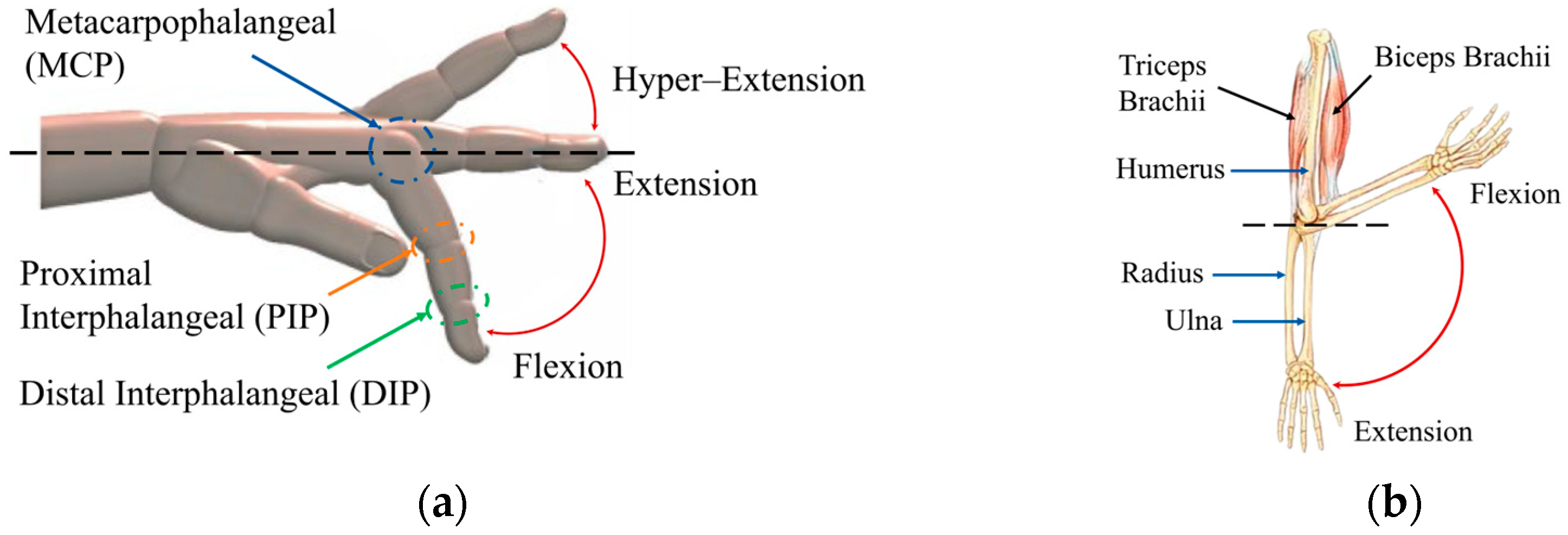
Human fingers complete the functional system of the distal upper limb, representing an essential component for fine object manipulation. Each finger (excluding thumb) comprises three phalanges interconnected by metacarpophalangeal (MCP), proximal interphalangeal (PIP), and distal interphalangeal (DIP) joints, as shown in Figure 2a. Flexion–extension movements are fundamental for rehabilitation therapies. The thumb’s two-phalanx structure and characteristic inclination require specific design considerations.
Figure 2. Schematic representation of finger and elbow movements: (a) flexion–extension of the fingers with main joints; (b) flexion–extension of the elbow showing the muscles and bones involved.
The elbow joint is a crucial component of the upper limb kinematic chain, enabling precise hand positioning and efficient force transmission during manipulation tasks. It consists of the humeroulnar, humeroradial, and proximal radioulnar joints enclosed within a common capsule []. As illustrated in Figure 2b, flexion and extension, primarily driven by the biceps brachii and triceps brachii, respectively, occur along a uniaxial path ranging from 0° to 145°.
Clinical impairments affecting these joints, from trauma, neurological disorders, or post-surgical conditions, significantly compromise functional autonomy. The proposed exoskeleton specifically targets coordinated recovery of all three joint systems through active or passive assistance strategies.

2.2. Kinematic and Dynamic Analysis of the System

Comprehensive kinematic and dynamic analyses were conducted to determine geometric relationships, force requirements, and actuator specifications for each subsystem. The dynamic simulations presented in this section were performed using MATLAB Simscape Multibody (R2025a, MathWorks, Natick, MA, USA), a multibody dynamics simulation toolbox. Anthropometric parameters including segment masses, lengths, centers of mass, and moments of inertia were obtained from standardized databases for the 50th percentile male [,]. Joint stiffness values representing passive elastic resistance were derived from experimental literature [,]. The models employed rigid body dynamics with the following key assumptions: (1) frictionless revolute joints for finger, wrist, and elbow articulations; (2) massless, inextensible cables with contact friction coefficient μ = 0.15 at pulley interfaces; (3) quasi-static analysis for wrist and finger systems where inertial forces are negligible compared to elastic resistance; (4) dynamic analysis for elbow system to capture inertial effects during movement initiation. Contact between cables and mechanical stops was modeled using penalty-based formulations with stiffness k = 1000 N/m and damping c = 10 Ns/m. Gravitational acceleration was set to 9.81 m/s2 in the vertical direction.
The finger actuation system has been designed to replicate the natural flexion and extension movements through a cable-driven mechanism that employs mechanical stops to ensure the correct joint configuration. Each finger was modeled as a serial kinematic chain with three degrees of freedom. The forward kinematics are defined by
x = L 1 + L 2 cos θ 1 + L 3 cos ( θ 1 + θ 2 ) + L 4 cos ( θ 1 + θ 2 + θ 3 )
y = L 2 sin θ 1 + L 3 sin ( θ 1 + θ 2 ) + L 4 sin ( θ 1 + θ 2 + θ 3 )
where L 1 , L 2 , L 3 , L 4 represent the phalangeal segment lengths, and θ 1 , θ 2 , θ 3 are the relative joint angles of the metacarpophalangeal (MCP), proximal interphalangeal (PIP), and distal interphalangeal (DIP) joints, respectively.
The system employs mechanical stops positioned on phalanges to achieve desired configurations without direct joint actuation. Optimal stop positioning follows geometric relationships ensuring sequential contact. For a generic segment with desired angle β , the stop height b and cable shortening a satisfy
α = 180 ° β 2 ,     a = c · cos α ,     b = c · s i n ( α )
where c is the distance between rotation centers.
For the thumb with initial inclination γ :
α = 180 ° θ γ 2
Dynamic analysis using multibody models with anthropometric data and literature-derived joint stiffnesses [] indicated that average forces of 10 N move the index finger.
The wrist employs a parallel cable-driven robot (CDPR) configuration enabling three degrees of freedom: flexion–extension α , radial–ulnar deviation β , and pronation–supination γ . For each cable i , the position vector b i represents the connection point on the end-effector. The transformed position in the fixed frame is
r i = R ( α , β , γ ) · b i
where the rotation matrix R α , β , γ incorporates sequential rotations.
The length of each cable is calculated as
L i = A i B i
Cable attachment coordinates were parametrized based on average anthropometric dimensions from standardized databases [], as detailed in Table 1. The strategic positioning of attachment points at specific percentages of hand and forearm length ensures optimal force transmission while accommodating anatomical variations. Optimization of these attachment positions significantly reduced required forces.
Table 1. Coordinates of the attachment points, reported as percentages relative to the total length of the corresponding body segment.
Dynamic simulations of the wrist system revealed force requirements and cable displacements in Table 2. These values, from the optimal attachment configuration in Table 1, informed the selection of appropriate servo motors for wrist actuation.
Table 2. Maximum forces and cable shortening for wrist movements, obtained from multibody simulations using the optimal attachment configuration.
The elbow system utilizes a single-cable mechanism with fixed shoulder anchor point (Figure 3). The kinematic model considers the forearm (link L 2 ) rotating about the elbow joint, with the biceps (link L 1 ) fixed. The kinematic equations of the system are
x a = x 0 + L 1 c o s ( q 1 ) + L 2 cos ( q 1 + q 2 ) y a = y 0 + L 1 s i n ( q 1 ) + L 2 sin ( q 1 + q 2 )
with L 1 fixed, only q 2 (forearm rotation angle) remains as the control variable.
Figure 3. Two-dimensional scheme of the prototype for the implementation of the elbow: (a) kinematic diagram; (b) initial and final configuration of the mechanism; (c) trend of cable tension over time.
The dynamic simulation from a near-singular configuration (Figure 3a,b) showed an initial peak tension of 146 N to overcome forearm inertia, later stabilizing at lower values during motion (Figure 3c). This was expected, as the system first must overcome static inertia. Considering a 16 mm pulley radius and friction losses along the cable path, this corresponds to about 24 kgfcm torque. An INJORA servomotor with 35 kgfcm stall torque was chosen, providing a 1.45 safety factor for reliable operation.
The force requirements derived from dynamic analyses guided actuator selection and cable configuration. A single-cable approach was adopted for each degree of freedom, reflecting the assistive nature of the device. In rehabilitation applications, exoskeleton provides supplementary forces that reduce muscular effort while allowing patients to retain control and voluntary participation. Unlike fully actuated systems that generate movement independently, the device delivers only the assistance necessary to achieve measurable reductions in muscle activation: approximately 10–20 N for wrist movements and up to 146 N initial peak for the elbow, as confirmed by EMG analysis (Section 6).
Antagonistic cable pairs were avoided to minimize mechanical complexity, simplify routing, and reduce the number of actuators, thereby lowering weight and cost. Movement reversal is achieved through natural return forces from gravity, tissue elasticity, and residual muscle activity, while cable assistance supports the primary movement directions where weakness is most pronounced. This strategy, validated in previous cable-driven rehabilitation devices [,], aligns with motor learning principles emphasizing that active patient involvement, rather than passive motion, promotes neuroplasticity and functional recovery.

2.3. Product Design Specifications (PDS)

The PDS synthesize all technical, functional, and operational requirements derived from preliminary analyses, comparative evaluations, and kinematic/dynamic studies. Table 3 presents the comprehensive PDS that guided prototype development.
Table 3. Product Design Specification (PDS) of the developed device.
The PDS validation through prototype construction confirmed the correctness of design choices and methodological effectiveness, ensuring that all specified requirements were met while maintaining portability, cost-effectiveness, and clinical applicability. Similar systematic design methodologies for multi-DOF rehabilitation exoskeletons have demonstrated the importance of integrating fabrication constraints, control considerations, and kinematic analysis from the early design phase [,].

3. System Design and Modelling

The cable-driven parallel exoskeleton development required a comprehensive design approach addressing multiple engineering challenges while maintaining clinical effectiveness, portability, and cost-efficiency. The system architecture overcomes limitations of existing rehabilitation devices by integrating multiple degrees of freedom into a single modular platform simultaneously addressing elbow, wrist, and finger rehabilitation.
The design philosophy focuses on separating the actuation system from limb-mounted components, minimizing weight on the patient’s arm while maximizing therapeutic effectiveness. This resulted in a dual-component system: a lightweight limb-mounted module and a backpack-mounted motor unit.
Figure 4 illustrates the complete system architecture. The modular design comprises five distinct limb-mounted modules strategically placed along the upper limb, while all motors, control electronics, and power systems are housed in a dedicated backpack unit constructed with a flexible TPU base plate. The limb-mounted components, fabricated using 3D printing with PLA material, serve exclusively as cable routing guides and attachment points, connected via a pulley transmission system mounted on a breadboard.
Figure 4. Complete CAD model of the cable exoskeleton, showing the general layout of the system.

3.1. Design Philosophy and Innovation

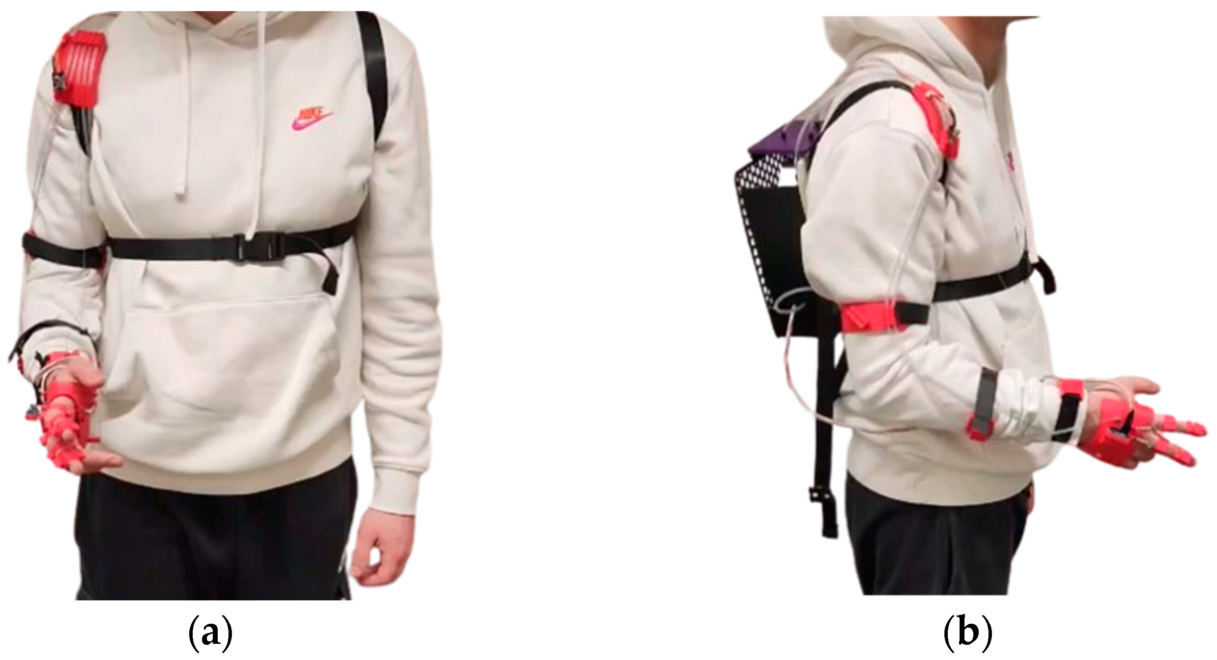
The developed exoskeleton embodies a design philosophy prioritizing portability, user comfort, and therapeutic effectiveness through strategic architectural decisions that distinguish it from conventional rehabilitation devices. Figure 5 illustrates the physical prototype in the worn configuration, demonstrating the practical implementation of the modular design concept.
Figure 5. Physical prototype of the cable-actuated exoskeleton: (a) front view of the worn system; (b) side view of the worn system.
The cable-driven architecture represents a deliberate design choice balancing biomechanical requirements with practical rehabilitation constraints. The 7-cable system provides unidirectional assistive forces along primary movement directions (elbow flexion, wrist flexion/extension, radial/ulnar deviation, pronation/supination, and finger flexion) without antagonistic cable pairs. This approach is justified for rehabilitation applications where patients retain residual voluntary motor control, gravity and elastic tissue provide natural return forces, and mechanical simplicity reduces control complexity and device weight. The unidirectional assistance paradigm has demonstrated effectiveness in previous cable-driven rehabilitation systems [,,,] and aligns with understanding that motor recovery is optimized when patients actively participate in movement generation [].
The fundamental innovation is the complete separation of actuation mass from the patient’s limb. Unlike traditional exoskeletons that distribute motors along the kinematic chain [,], all actuators are consolidated within a backpack unit, greatly reducing limb-mounted inertia (80–150 g per module vs. 300–800 g), simplifying the mechanical design, and improving thermal management and maintainability. Thermal performance under extended operation is discussed in Section 6.4. Cable routing was optimized to maintain wrap angles of 90–150° at attachment points, minimizing friction losses. The unidirectional cable forces inherently provide a fail-safe mechanism: cable breakage results in loss of assistance rather than resistive forces that could injure the patient.
Material selection reflects the accessibility-focused design philosophy. Exclusive use of 3D-printed PLA for structural components and TPU for the flexible backpack plate enables rapid customization and decentralized manufacturing. The modular architecture allows individual component replacement without system-wide disassembly. Key design refinements include single-cable spring-return mechanisms for fingers, IMU sensors for closed-loop feedback, and optimized cable attachment geometry (Table 1 and Table 2) reducing required forces by 15–20%.

3.2. Modular Architecture and Component Design

The modular architecture comprises five distinct limb-mounted modules, each optimized for specific functional requirements while maintaining minimal weight and ergonomic comfort. Figure 6 presents detailed views of all individual modules.
Figure 6. Detailed view of the 3D models of the individual modules: (a) wrist module; (b) forearm module; (c) biceps module; (d) shoulder module; (e) glove; (f) finger rings.
The wrist module (Figure 6a) incorporates a cable attachment point for elbow actuation and houses the primary IMU sensor for real-time motion detection. The forearm module (Figure 6b) functions as an intermediate cable guidance system, ensuring proper routing and maintaining system stability during movement. Its anatomically optimized geometry provides secure fit without compromising limb movement patterns.
The biceps module (Figure 6c) represents the most complex limb-mounted component, incorporating multiple cable routing channels. Vertical channels guide wrist movement cables, while lateral passages house finger actuation cables, creating optimal angular configurations for effective multi-degree-of-freedom control. The shoulder module (Figure 6d) ensures proper cable route from limb to backpack while housing the infrared sensor for remote system control.
The manual interface consists of a custom-designed glove (Figure 6e) incorporating cable attachment points and spring-return mechanisms. Unlike previous implementations requiring dual-cable systems, the current design employs a single-cable approach with mechanical springs providing return force, reducing complexity while improving motor efficiency. The glove integrates the primary IMU sensor and provides secure mounting points for finger fastening rings (Figure 6f), individually sized for optimal fit.

3.3. Backpack Unit and Actuation System

The backpack structural support is fabricated from flexible TPU, chosen for anatomical adaptability and mechanical resistance. Figure 7a shows the base plate design featuring an integrated honeycomb pattern optimizing the lightness-strength ratio while improving ventilation and contributing to thermal dissipation of electronic components. The plate dimensions (256 × 256 mm) ensure compatibility with common 3D printing equipment while providing sufficient mounting area. The fastening system integrates adjustable straps with upper/lower buckles for load distribution, while additional chest straps with quick-release mechanisms ensure secure anchorage and dynamic stability.
Figure 7. Detailed view of the 3D backpack model: (a) CAD of the flexible TPU plate with honeycomb cover; (b) housing of individual motor modules with functional division highlighted—elbow motor in yellow, finger motors in blue, wrist motors in green.
PLA was selected for structural components and TPU for the flexible backpack plate due to their availability, well-established 3D printing parameters, and suitable mechanical properties for the expected loads. PLA offers sufficient tensile strength (50–70 MPa) and elastic modulus (2–3 GPa) for cable routing modules and attachment points subjected to forces of 10–20 N during typical rehabilitation exercises. TPU, with its flexibility (Shore 85–95 A) and tear resistance, is appropriate for the backpack interface, ensuring conformal contact with different body shapes. The prototype includes safety factors of 1.5–2.0 based on static loading analysis (Section 2.2). However, fatigue testing under cyclic loads representative of intensive rehabilitation use (thousands of movement cycles) is still pending.
The motor unit (Figure 7b) incorporates seven servomotors distributed according to functional criteria: four DS04-NFC continuous rotation servos (18 kgfcm each) dedicated to wrist movements, two AS3103PG servos (15 kgfcm) for finger actuation, and one high-torque INJORA servo (35 kgfcm) for elbow flexion–extension. This distribution enables differential control of primary degrees of freedom while maintaining balance between dynamic performance, energy efficiency, and compactness. Motors are arranged in compact, stackable configurations on dedicated PLA supports, allowing independent positioning that optimizes cable routing while ensuring robustness and modularity.
Motion transmission is achieved through a cable system with dedicated pulleys for each motor. Figure 8 shows the pulley assembly, integrated into motor supports with an external diameter of 35 mm. The pulleys (Figure 8a) include cable attachment points, manual tensioning mechanisms operated by dedicated keys (Figure 8b), and anti-unwinding systems (Figure 8c). This integration reduces assembly tolerances, simplifies adjustments, and maintains proper alignment during operation. Cable layout optimization ensures correct trajectories and pulls angles. Cables connected to the upper glove sections pass through forearm modules to produce coordinated movements, while those attached to lower sections bypass them to create alternative angular configurations, enabling three-dimensional wrist control. The single-cable configuration for each movement direction, instead of antagonistic pairs, reflects the assistive design philosophy: the device provides unidirectional forces that reduce muscular effort during voluntary motion, while gravity, tissue elasticity, and residual muscle activity enable movement reversal. This approach lowers mechanical complexity, reduces the number of actuators (and overall weight from about 2.5–3.0 kg to 1.2–1.5 kg), and simplifies control algorithms while maintaining therapeutic effectiveness for patients with partial motor function. Cable routing geometry was refined iteratively to maintain wrap angles between 90° and 150° at pulley contact points, minimizing friction and preventing slippage. PLA covers protect the cables from interference and preserve system alignment despite 3D printing tolerances.
Figure 8. Three-dimensional models of the power transmission system: (a) front and rear views of the pulleys; (b) manual tensioning tool; (c) pulley anti-unwind mechanisms.
The cable transmission system is affected by non-ideal factors influencing control accuracy. Cable slack is minimized through manual pre-tensioning (2–5 N) and routing with 90–150° pulley wrap angles. Friction losses (μ ≈ 0.10–0.15, nylon on PLA) are offset by motor safety factors (1.45–1.8×) and IMU-based feedback. Cable elasticity (~4–5 GPa) and 3D-printing backlash (±0.2–0.3 mm) add compliance that enhances safety but limits bandwidth. The PID controller compensates for deviations by adapting motor output to maintain target joint angles.
In summary, the system design achieves portability (1.2–1.5 kg total), multi-degree-of-freedom integration, and cost-effectiveness through strategic separation of actuation from limb-mounted structures. The modular architecture, comprising wrist, forearm, biceps, shoulder, and hand modules integrated with the backpack motor unit, offers a flexible and effective solution for comprehensive upper limb rehabilitation, suitable for both clinical and home-based applications.

4. Control Architecture and Implementation

Control architecture represents a fundamental component ensuring both efficiency and safety during rehabilitation exercises. The primary design objective implements a responsive control system with real-time monitoring capabilities, allowing immediate pause or emergency shutdown to maintain patient safety.
The system facilitates assisted movements of three main joint groups: elbow, wrist, and fingers. Specifically, the system enables forearm excursion along the sagittal plane (elbow flexion/extension), hand movement along sagittal, transverse, and frontal axes (wrist movements), and index/middle finger opening and closing motions.

4.1. Hardware Components and System Architecture

The control system core is based on an Arduino Mega 2560 Rev3 microcontroller board, selected for adequate computational capacity, multiple I/O ports, and proven reliability in mechatronic applications. Real-time position and orientation feedback is provided by an Inertial Measurement Unit (IMU) sensor (MPU-9250/6500), incorporating accelerometer and gyroscope capabilities enabling continuous monitoring of joint angles and angular velocities essential for closed-loop control.
The human–machine interface consists of a Keyes infrared remote control communicating with an infrared receiver (VS1838B), allowing users to select specific movement patterns, activate standby mode, trigger emergency shutdown, and pause operations. Mechanical actuation is achieved through distributed servo motor configuration: one continuous rotation servo (INJS035-360, 35 kgfcm) for forearm movement, four continuous rotation servos (DS04-NFC) for wrist articulation, and two continuous rotation servos (AS3103PG) for finger movements. Power distribution is managed through a 7.4 V LiPo battery system. Figure 9 illustrates complete control of architecture.
Figure 9. Block diagram of the exoskeleton control system architecture.

4.2. Sensor Calibration and System Identification

Accurate sensor calibration is essential for reliable control performance. The IMU calibration process addresses systematic errors including bias, drift, and noise significantly impacting measurement accuracy [].
Accelerometer calibration follows a systematic six-position procedure where the sensor is positioned to measure gravity along each axis. Bias values are estimated as
a b x 1 n x i = 1 n x a x , i g ,     a b y 1 n y i = 1 n y a y , i g ,     a b z 1 n z i = 1 n z ( a z , i g )
Gyroscope bias estimation employs a Kalman filter approach. The state vector includes angular velocity and bias: x k = ω   ω b T , with system matrices A = I 2 × 2 and measurement matrix C = 1   1 . Process and measurement noise covariance matrices are
W = 0.001 0 0 0.01 ,     V = 0.01
The process noise covariance matrix W and measurement noise covariance matrix V were empirically tuned from IMU specifications and preliminary tests. The diagonal structure of W assumes independent noise in angular velocity (0.001) and bias (0.01) states, with the larger bias variance reflecting greater uncertainty in drift. The measurement noise variance V = 0.01 was derived from MPU-9250/6500 datasheet data (noise density ≈ 0.005 °/s/√Hz) and confirmed through static noise floor tests. These values yielded satisfactory results in experiments, though further optimization using adaptive or maximum-likelihood estimation could enhance filter performance, especially during high-acceleration movements. Table 4 presents calibrated bias values.
Table 4. Calibrated bias values for accelerometer and gyroscope.
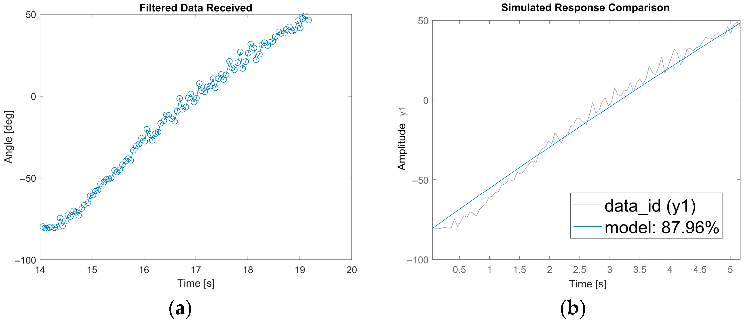
System identification was implemented to develop accurate mathematical models for PID controller tuning. Real-time angle measurements were collected with IMU positioned between elbow and hand during constant motor input (30 rpm). Data acquisition utilized serial communication (115200 baud) to transfer measurements to MATLAB (R2025a, MathWorks, Natick, MA, USA) for ARMAX model identification. The resulting discrete transfer function model is
A z y t = B z u t + C z e ( t )
where A ( z )   =   1     0.9987 z 1 , B ( z )   =   0.04317 z 1 , C ( z )   =   1     0.5612 z 1 .
Figure 10 shows experimental angle measurements and model validation achieving 87.96% fit, confirming model accuracy for controller design.
Figure 10. Experimental results: (a) trend of angles measured as a function of time; (b) validation of the ARMA model by comparing experimental data and simulated output (fit = 87.96%).
Based on the identified model, PID controller parameters were optimized using Simulink for elbow control. Wrist control employed empirical tuning to avoid multi-input system complexity. Finger movement control uses offline-calculated strategy based on experimental timing measurements. Table 5 summarizes the optimized parameters.
Table 5. PID controller parameters for different joint controls.
Closed-loop performance was evaluated experimentally via step responses. For elbow control, a 45° step produced a rise time (10–90%) of ~2.8 s, settling time (±2°) of 4.5 s, steady-state error <2°, and ~8% overshoot. Wrist pronation/supination with a 30° step yielded a rise time of 2.1 s, settling time of 3.8 s, steady-state error <2°, and 5% overshoot. These conservative responses reflect moderate controller gains (Kp = 0.9–1.2, Ki = 0.2–0.3, Kd = 0) prioritizing smooth, stable movements for rehabilitation. The absence of derivative action reduces high-frequency noise sensitivity, while small integral gains limit windup and overshoot. Robustness was verified across eight participants with varying limb lengths, weights, and joint stiffnesses, showing consistent tracking without individual tuning. Moderate gains provide sufficient stability margins for inter-subject variability. Formal robustness analysis was not performed. Estimated closed-loop bandwidth (~0.3–0.4 Hz) is adequate for slow rehabilitation cycles (5–8 s) but may be insufficient for rapid movements or high-frequency disturbance rejection.

4.3. Control Logic and Safety Implementation

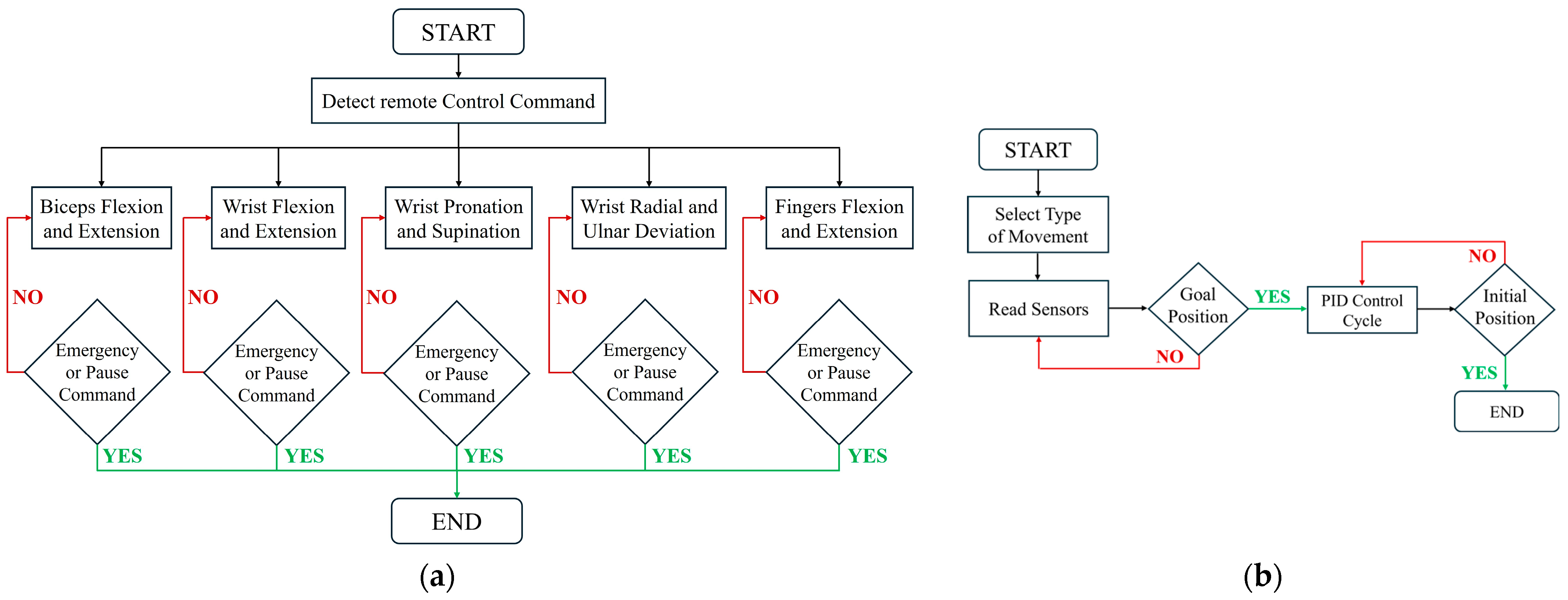
The control system implements a state-machine architecture initiated by infrared remote command detection. Upon command recognition, the corresponding movement pattern executes continuously until “Pause” or “Emergency” commands are received. Pitch and roll angles derived from accelerometer and gyroscope data are filtered using Kalman filtering to minimize noise and provide smooth control signals.
Figure 11a shows the master control flowchart for five movements: elbow flexion/extension via PID, wrist flexion/extension and finger movements through timed sequences, wrist pronation/supination under PID, and radial/ulnar deviation regulated by PID.
Figure 11. Control architecture: (a) Master control flowchart; (b) Flowchart showing the operational sequence of the exoskeleton’s five primary movements: elbow flexion/extension, wrist movements, and finger actuation.
Figure 11b presents the general execution logic. For closed-loop movements (elbow, wrist pronation/supination, radial/ulnar deviation), the system continuously reads IMU sensors, checks goal positions within ±2° tolerance, and updates commands at 100 Hz until the target is reached or interrupted. Open-loop movements (wrist flexion/extension, fingers) follow predefined timed sequences with periodic emergency or pause checks.
The control system has multiple safety layers: (1) a pause function with a 500 ms deceleration ramp, (2) an emergency stop disabling motors within 50 ms, (3) real-time IMU monitoring at 100 Hz, and (4) software limits keeping joints within safe ranges (Table 2). The control loop responds in under 100 ms, with PID-controlled movements accurate to ±2°, reliable emergency stops, and Kalman-filtered feedback. A hybrid approach uses PID for the elbow and wrist and open-loop control for the fingers, saving resources while ensuring effective rehabilitation. The modular design allows joints to operate independently while coordinating, supporting varied upper-limb exercises. PID controllers (Table 5) use a PI structure (Kd = 0) with small integral gains (Ki = 0.2–0.3) to reduce windup. Limited motion exercises with frequent reversals naturally limit integral buildup. Motor saturation is rare due to conservative actuator sizing (safety factors 1.45–1.8) and moderate speeds. Future versions should add explicit anti-windup methods to maintain performance under spasticity or unexpected resistance.

5. Experimental Validation

The experimental validation phase assessed exoskeleton effectiveness through comprehensive electromyographic analysis, quantifying muscle activation reduction during assisted rehabilitation exercises to establish therapeutic potential. The validation protocol incorporated standardized procedures for participant selection, instrumentation setup, data acquisition, and analysis, ensuring reproducible and clinically meaningful results.

5.1. Experimental Setup and Protocol

Eight healthy male participants were recruited for this study (age 26.88 ± 3.72 years, body weight 71.56 ± 8.91 kg, height 1.76 ± 0.05 m, mean ± SD). Detailed anthropometric measurements are presented in Table 6. Inclusion criteria require no history of musculoskeletal or neurological disorders affecting the upper limb, normal joint range of motion, and adequate muscle strength. Verbally informed consent was obtained from all participants prior to participation. The study was conducted in accordance with the principles of the Declaration of Helsinki [].
Table 6. Participant characteristics and anthropometric measurements.
The experiment employed a within-subjects design with repeated measurements. Participants performed four functional upper limb exercises under two conditions: (1) Exo Off, exoskeleton worn but unpowered (passive condition), and (2) Exo On, exoskeleton powered and actively assisting movements. The exercise order was randomized using a Latin square design to control order effects. Each condition was separated by a 25 min rest period to minimize carryover and fatigue effects. All exercises were performed at a self-selected comfortable speed without external load. Table 7 summarizes the standardized exercise protocol used to assess exoskeleton performance across different movement patterns and joint combinations.
Table 7. Experimental protocol specifications for the four functional upper limb exercises performed under Exo Off and Exo On conditions.
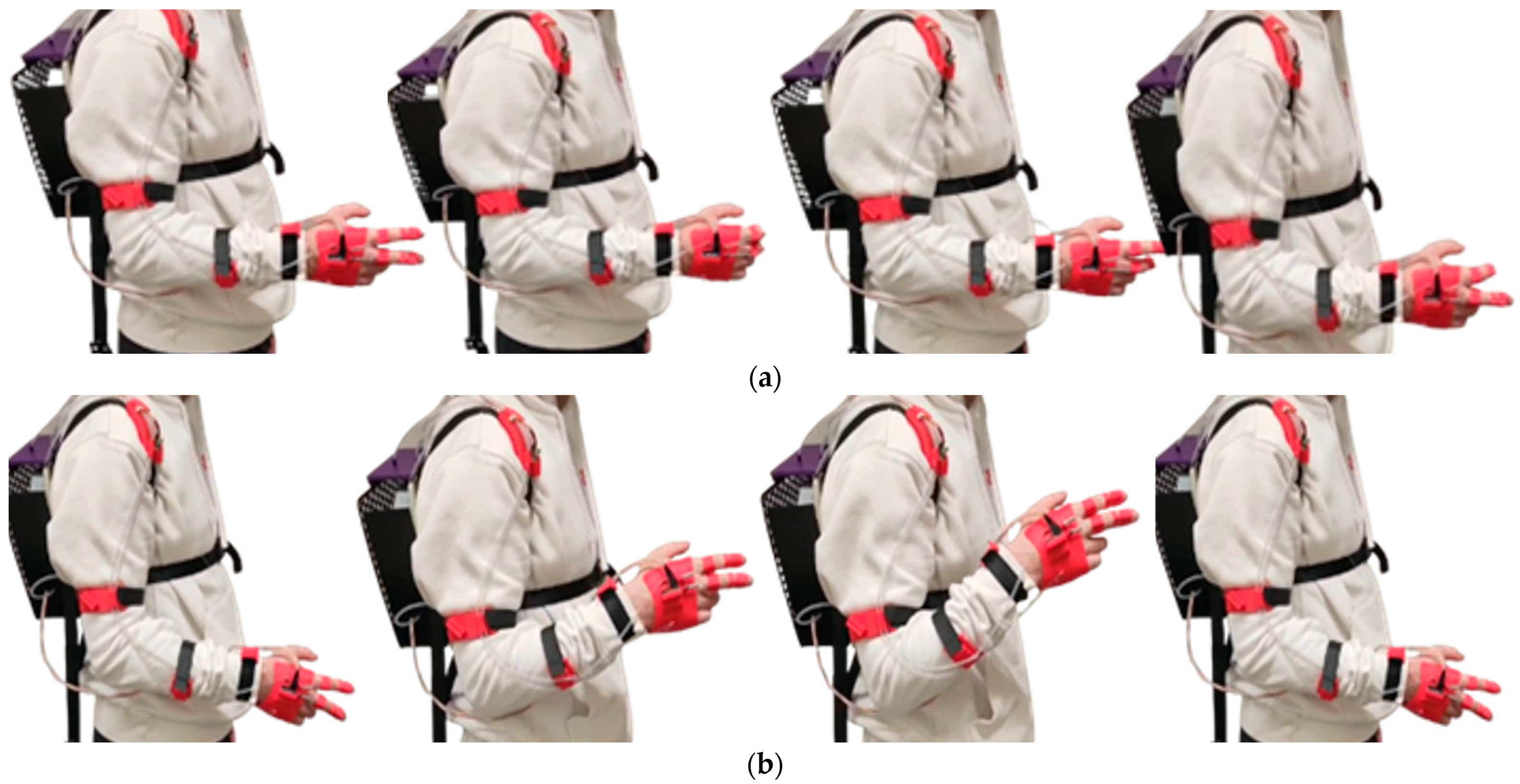
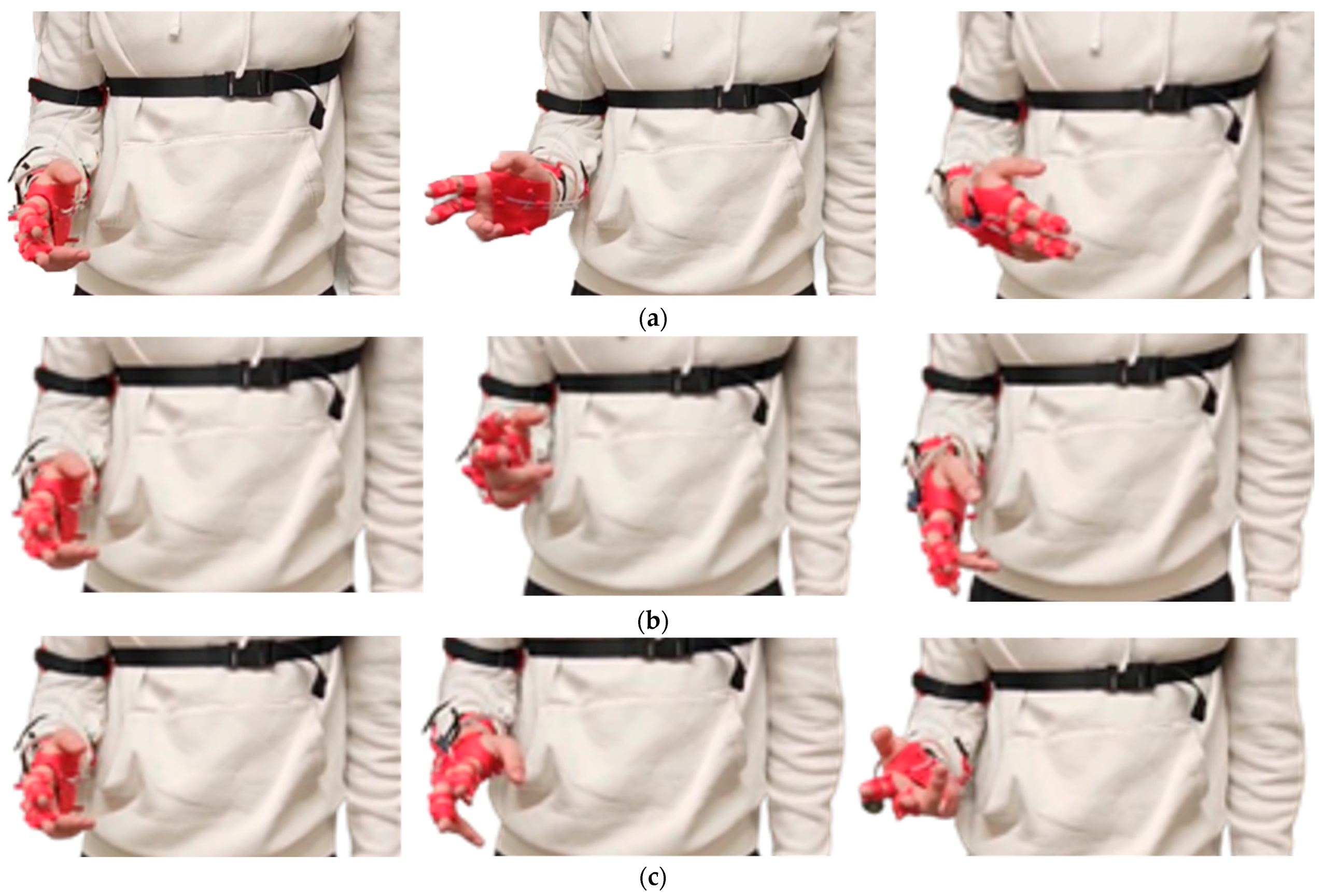
Figure 12 and Figure 13 illustrate the complete experimental protocol implementation, showing participants performing all four exercise categories under powered exoskeleton conditions. The image sequences demonstrate the system’s capability to assist multi-planar movements across different joint complexes while maintaining ergonomic fit and cable routing integrity throughout complete range-of-motion cycles.
Figure 12. Execution of motor sequences during the experimental tests: (a) finger flexion and extension; (b) biceps brachii flexion and extension.
Figure 13. Execution of motor sequences during the experimental tests: (a) wrist flexion and extension; (b) radial and ulnar deviation of the wrist; (c) wrist pronation and supination.

5.2. EMG Data Acquisition and Processing

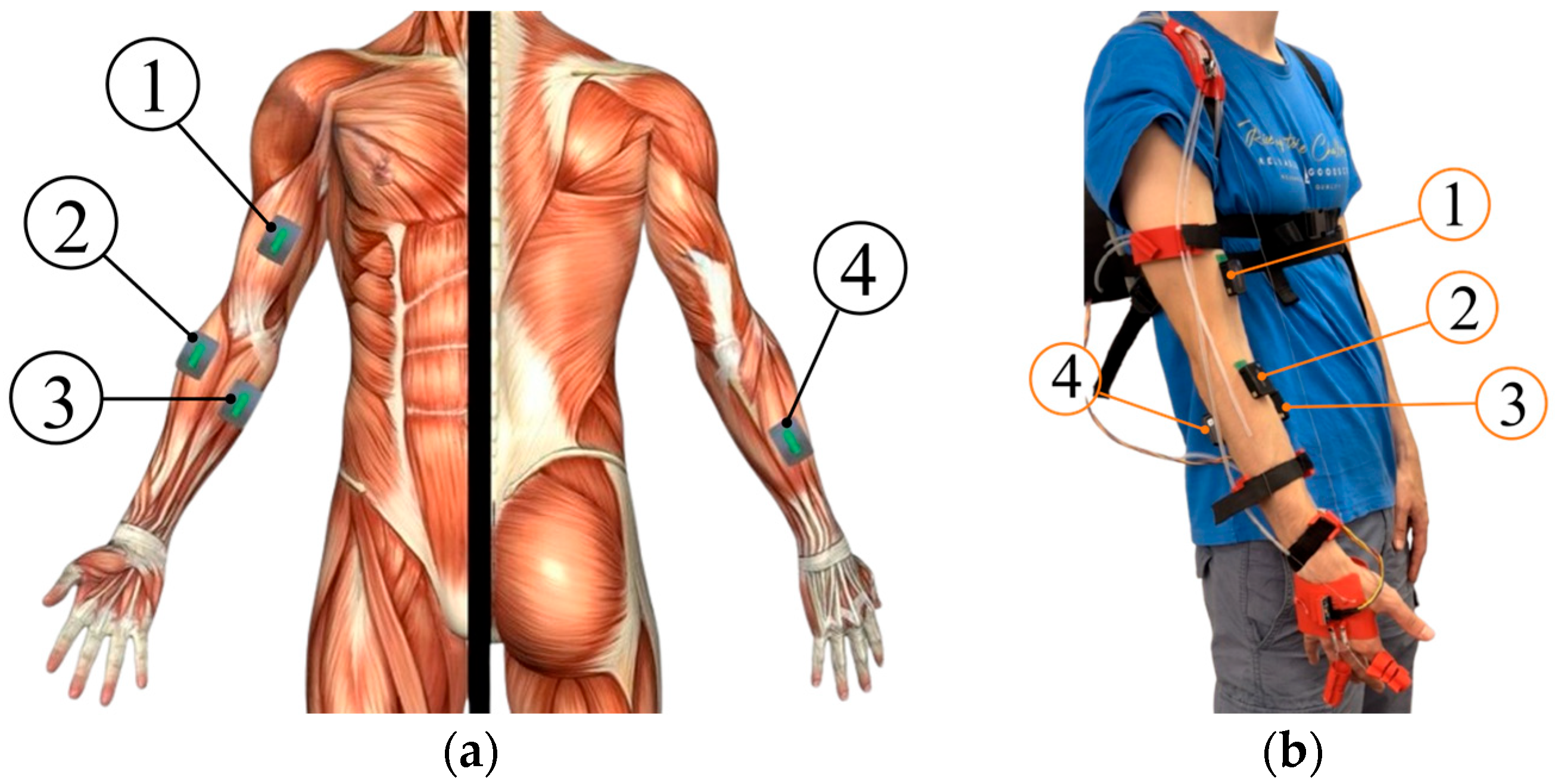
Surface electromyography (EMG) was recorded using a wireless multichannel EMG system (Delsys Trigno, Natick, MA, USA) with a sampling rate of 1000 Hz. Four bipolar surface electrodes were placed following the SENIAM guidelines [] on the dominant arm, as shown in Figure 14, monitoring the four main effector muscles of the myoelectric activity associated with these motor gestures (Table 8).
Figure 14. EMG sensor placement: (a) Anatomical location of acquisition points; (b) Practical application of EMG sensors on the subject (① Biceps Brachii, ② Brachioradialis, ③ Flexor Digitorum Profundus, ④ Extensor Digitorum Communis).
Table 8. Overview of monitored muscles and their biomechanical functions: BB (Biceps Brachii), BR (Brachioradialis), FDP (Flexor Digitorum Profundus), and EDC (Extensor Digitorum Communis).
Electrode placement followed standardized SENIAM recommendations [] to ensure reproducibility. The skin was prepared by shaving, light abrasion with sandpaper, and cleaning with 70% isopropyl alcohol to reduce impedance below 10 kΩ. All electrodes were oriented parallel to the presumed muscle fiber direction to optimize signal quality. Inter-electrode distance was maintained at 20 mm (fixed by the Trigno sensor geometry).
Before testing, maximum voluntary contraction (MVC) data were collected for EMG normalization following standard protocols []. Participants executed three 5 s maximal isometric contractions per muscle, with 2 min rest intervals between trials to prevent fatigue. The MVC protocol consisted of resisted elbow flexion at 90° with the forearm supinated for BB; resisted elbow flexion at 90° with the forearm in neutral position for BR; resisted finger flexion with the wrist stabilized in neutral position for FDP; and resisted finger extension with the wrist stabilized in neutral position for EDC. The highest root mean square (RMS) value obtained across the three trials was used as the 100% MVC reference for subsequent normalization.
Raw EMG data were processed offline in MATLAB (R2025a, MathWorks, Natick, MA, USA) using a standardized pipeline. First, motion artifact removal was performed using an adaptive thresholding technique that removed samples exceeding 4× the standard deviation of the baseline signal. Second, a 4th-order Butterworth bandpass filter (20–450 Hz) was applied to remove movement artifacts and high-frequency noise. Third, the filtered signal was rectified through full-wave rectification. Fourth, a moving average filter with a 50 ms window was applied to create a linear envelope. Finally, the smoothed RMS values were normalized to the maximum RMS value obtained during MVC trials, expressed as percentage of MVC (%MVC):
E M G n o r m a l i z e d = R M S T A S K / R M S M V C × 100
Muscle activation onset and offset were detected using a threshold-based algorithm. The smoothed EMG signal was considered “active” when it exceeded the baseline mean +2 standard deviations for a minimum duration of 100 ms. RMS values were calculated over the active portions of each movement cycle and averaged across all repetitions within a set, then across the three sets, yielding one representative value per participant.
All EMG recordings were visually inspected for artifacts, baseline drift, and signal saturation. A total of 8 participants × 4 exercises × 2 conditions × 3 sets = 192 trials were collected, with 4 trials (<2.1%) excluded due to electrode displacement during movement.

5.3. Statistical Analysis Framework

For each muscle-exercise combination, mean RMS values and standard deviations were calculated across all repetitions and sets. Data were aggregated at the participant level to avoid pseudo-replication, with each participant’s mean serving as the statistical unit (n = 8). Data normality was assessed using the Shapiro–Wilk test (α = 0.05) for each muscle-conditioning combination. All datasets passed the normality assumption (p > 0.05 for all comparisons), confirming the appropriateness of parametric statistical tests.
Given the within-subjects design, paired t-tests were conducted to evaluate differences between Exo Off and Exo On conditions for each muscle independently. To assess overall system effectiveness across all muscles simultaneously, a two-way repeated measures ANOVA was conducted with Factor 1 (Condition): Exo Off vs. Exo On (within-subjects), Factor 2 (Muscle): BB, BR, FDP, EDC (within-subjects), and dependent variable: RMS (%MVC). Effect sizes were quantified using Cohen’s d for paired samples:
d = x ¯ d i f f s d i f f
where x ¯ d i f f is the mean difference between conditions (Exo Off—Exo On) and s d i f f is the standard deviation of differences. Effect sizes were interpreted as: small (d = 0.2), medium (d = 0.5), or large (d = 0.8) according to Cohen’s conventions.
For the 16 individual muscle–exercise combinations, p-values were adjusted using the Benjamini–Hochberg procedure with a target FDR of 0.05. All statistical analyses were performed using MATLAB (R2025a). Statistical significance was set at α = 0.05. Results are reported as mean ± SD. The sample size of n = 8 provides 80% power to detect a medium-to-large effect size (d = 0.75) at α = 0.05 in paired comparisons. While this represents pilot validation with healthy participants, the consistent direction of effects across participants provides preliminary evidence supporting the device’s therapeutic potential.

6. Results and Performance Evaluation

The experimental validation provided comprehensive quantitative evidence of exoskeleton effectiveness in reducing muscle activation during upper limb rehabilitation exercises. Results demonstrate both global trends and muscle-specific patterns informing therapeutic potential and optimization strategies for the device.

6.1. Overall System Performance

Across all muscles and exercises, the exoskeleton showed a trend toward reduced muscle activation when powered on (Exo On) versus unpowered (Exo Off), though this was not statistically significant (p = 0.087, two-way repeated measures ANOVA, Figure 15). Mean RMS values were 10.40 ± 5.24%MVC for Exo On and 12.62 ± 5.91%MVC for Exo Off, representing a 2.22%MVC (21.3%) reduction with assistance.
Figure 15. Global comparison of muscle activation across all exercises. Box plots show RMS distributions for Exo Off vs. Exo On conditions. Boxes represent the 25th–75th percentiles, whiskers extend to 1.5 × IQR, circles denote individual participant means, and diamonds indicate group means (n = 128 per condition; 8 participants × 4 muscles × 4 exercises).
ANOVA revealed a significant main effect of Muscle (p = 0.020), indicating baseline differences among muscles, while no Condition × Muscle interaction (p > 0.05) suggested the exoskeleton’s effect was consistent across muscle groups.
The repeated measures ANOVA was used to maximize statistical power by accounting for within-subject correlations, addressing the limited sample size (n = 8). Despite this approach, the main effect of Condition approached but did not reach significance. The observed effect sizes (d = 0.70–0.79) were close to the detection threshold from the power analysis (d = 0.75), suggesting the study was slightly underpowered. A larger sample (n ≈ 12–15) would likely achieve statistical significance for the group-level effects.

6.2. Muscle-Specific Activation Patterns

Individual muscle responses to exoskeleton assistance exhibited moderate variability across participants, with effect sizes ranging from small to medium. Overall, muscle activation tended to decrease under the Exo On condition, although differences did not reach statistical significance. Table 9 summarizes the statistical results.
Table 9. Statistical summary of muscle-specific effects with values expressed as mean ± SD (n = 8).
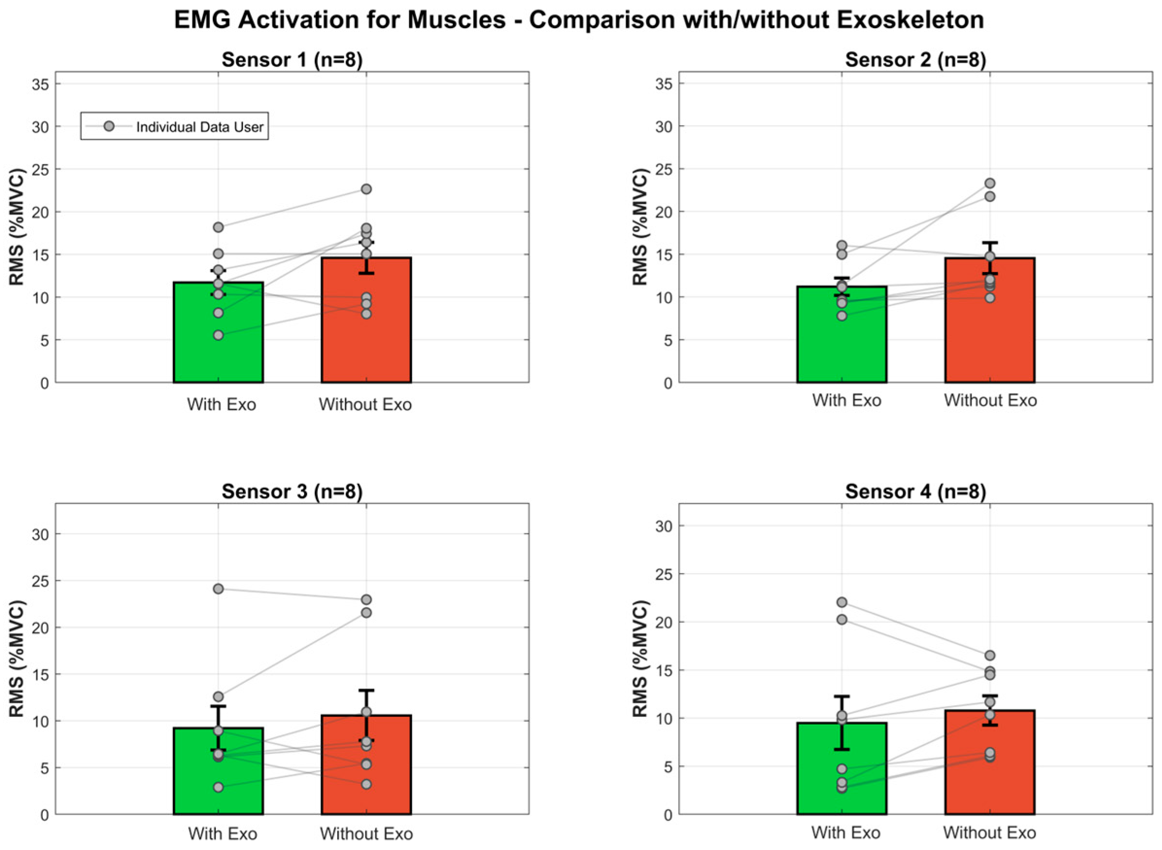
The biceps brachii (BB) showed mean activation of 11.70 ± 3.93%MVC with the exoskeleton powered on (Exo On) compared to 14.60 ± 5.10%MVC when unpowered (Exo Off), representing a 2.90%MVC (24.8%) reduction. These decreases approached statistical significance (t7 = 1.966, p = 0.090) with a moderate effect size (Cohen’s d = 0.695).
The brachioradialis (BR) exhibited a similar pattern, with activation decreasing from 14.54 ± 5.13%MVC (Exo Off) to 11.20 ± 2.89%MVC (Exo On), corresponding to a 3.34%MVC (29.8%) reduction (t7 = 2.222, p = 0.062, Cohen’s d = 0.786).
In contrast, the flexor digitorum profundus (FDP) and extensor digitorum communis (EDC) showed smaller, non-significant reductions. FDP activation decreased by 1.35%MVC (14.7%, p = 0.387, Cohen’s d = 0.326), while EDC decreased by 1.29%MVC (13.6%, p = 0.441, Cohen’s d = 0.289).
The biomechanical mechanism underlying these activation reductions can be understood through force equilibrium. When the exoskeleton provides assistive forces, it contributes to the joint torque required for movement, reducing the torque needed from muscles. The observed 24.8% reduction in biceps brachii activation indicates that exoskeleton assistance reduced muscular torque requirements by approximately one-quarter, consistent with designed assistance levels (Section 2.2). The moderate effect sizes (Cohen’s d = 0.70–0.79) for proximal muscles indicate clinically meaningful reductions in effort. Individual participant data showed substantial variability. For biceps brachii and brachioradialis, 6 of 8 participants (75%) demonstrated reduced activation, with reductions ranging from 5 to 30% of baseline. This variability was more pronounced for the digital muscles.
Figure 16 provides visual comparison of muscle activation patterns.
Figure 16. Muscle activation comparison between Exo Off and Exo On conditions. Bar plots show mean RMS values (±SE) normalized to MVC for the four monitored muscles. Points represent participant means connected by lines to illustrate within-subject changes.
An important consideration is that only agonist muscles were monitored in this study. The observed reductions in primary movers reflect decreased effort consistent with the exoskeleton’s assistive function. However, antagonist muscles such as the triceps brachii were not monitored. While the cable driven design facilitates agonist function without resisting antagonists, we cannot exclude potential contributions from altered co contraction patterns. Future studies should monitor both agonist and antagonist muscle groups to fully characterize neuromuscular effects.

6.3. Exercise-Dependent Effects

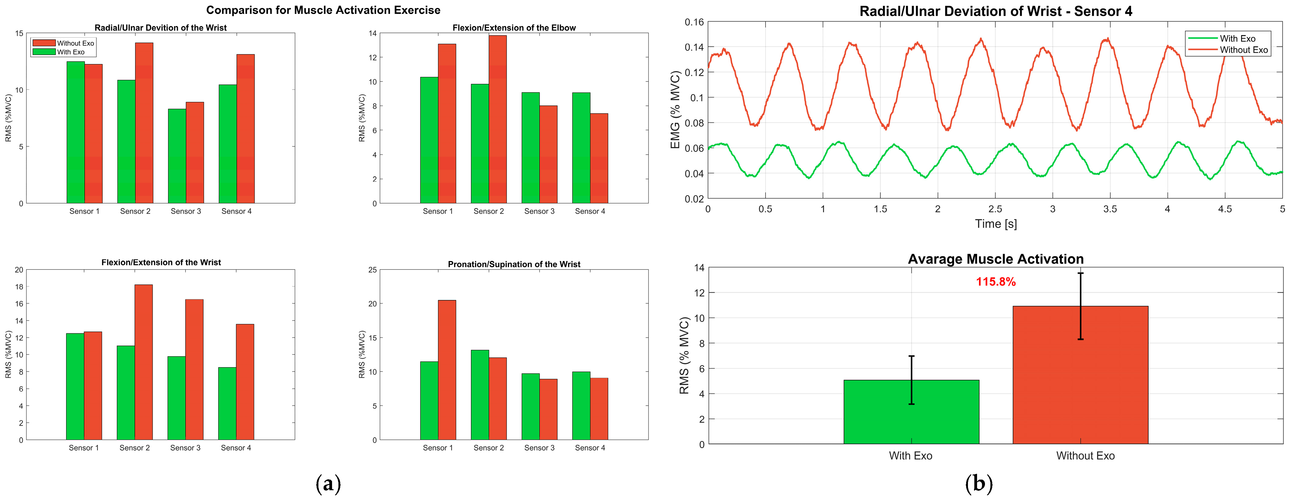
Analysis of muscle activation patterns across the four exercises revealed task-dependent variation in exoskeleton effectiveness, as shown in Figure 17a and Table 10. Across sixteen pairwise comparisons (4 muscles × 4 exercises), only one reached statistical significance: brachioradialis during radial/ulnar wrist deviation (p = 0.045).
Figure 17. Muscle activity during exercises: (a) Mean RMS values of the four muscles across the four exercises, with bars grouped by condition (Exo Off vs. Exo On); (b) EMG temporal analysis during a representative radial/ulnar deviation test, showing five consecutive repetitions (Rep 1–Rep 5) of the filtered signals of the four monitored muscles.
Table 10. Muscle activation by exercise and condition: positive Δ values indicate reduced activation with exoskeleton (Exo Off—Exo On).
Radial/Ulnar Deviation showed the most consistent benefit (Figure 17a, top-left). Brachioradialis activation significantly decreased from 14.1%MVC (Exo Off) to 10.8%MVC (Exo On), a 3.3%MVC reduction (23.4%, p = 0.045, d = 0.86). Biceps brachii showed minimal change, while digital muscles exhibited non-significant increases (Table 10).
Elbow Flexion/Extension produced mixed results (Figure 17a, top-right). Brachioradialis showed the largest reduction (4.0%MVC, 40.8%), approaching significance (p = 0.074), while biceps brachii demonstrated a moderate decrease (2.7%MVC, 26.2%, p = 0.213). Both digital muscles showed minor reductions (Table 10).
Wrist Flexion/Extension elicited the largest activation reductions, averaging 4.8%MVC across muscles (Figure 17a, bottom-left), though high variability prevented significance. Brachioradialis showed the greatest reduction (7.2%MVC, 65.5%, p = 0.193), followed by FDP (6.7%MVC, 68.4%, p = 0.087) and EDC (5.1%MVC, 60.0%, p = 0.074). Biceps brachii changed minimally (0.2%MVC, p = 0.901). Temporal EMG patterns (Figure 17b) showed consistent amplitude reductions throughout movement cycles.
Pronation/Supination produced variable responses (Figure 17a, bottom-right). Biceps brachii showed a substantial increase (9.0%MVC, 78.3%, p = 0.055), possibly reflecting counteraction of supination torque, while other muscles exhibited small, non-significant reductions.
When ranking exercises by average muscle activation reduction across all muscles, wrist flexion/extension showed the greatest potential benefit (mean Δ = 4.8%MVC), followed by pronation/supination (3.0%MVC), elbow flexion/extension (2.4%MVC), and radial/ulnar deviation (1.7%MVC). These findings suggest exoskeleton provides most effective assistance during wrist movements involving multiple degrees of freedom, particularly in the sagittal plane. The significant result for brachioradialis during radial/ulnar deviation indicates that frontal plane wrist control is reliably enhanced by the cable driven mechanism. However, substantial inter-individual variability across all exercises (coefficient of variation typically 30–60%) suggests that personalized control strategies may be necessary to achieve consistent benefits across diverse patient populations.

6.4. Study Limitations and Future Directions

While this study demonstrates the feasibility and potential effectiveness of the cable driven exoskeleton, several limitations warrant consideration. The experimental validation involved a small sample (n = 8) of healthy participants, limiting statistical power and generalizability. The substantial inter-individual variability (60–75% of participants showing activation reductions) highlights the importance of personalized control strategies and extended familiarization protocols to distinguish device effects from learning adaptations.
The cable driven architecture with unidirectional assistance represents a design trade-off prioritizing practical usability over biomimetic completeness []. While the human musculoskeletal system employs antagonistic muscle pairs, our 7-cable configuration assists only with primary movement directions, relying on gravity, tissue elasticity, and residual patient activity for movement reversal [,]. This approach reduces mechanical complexity and weight (from 2.5–3.0 kg to 1.2–1.5 kg) while maintaining therapeutic effectiveness. However, this may not optimally support patients with severe weaknesses requiring bidirectional assistance or tasks demanding high precision stabilization. Future iterations could investigate hybrid approaches combining unidirectional assistance with selective antagonistic actuation for enhanced stability.
A critical limitation is the restricted EMG monitoring scope, focusing exclusively on four agonist muscles without assessing antagonist activity. The triceps brachii, crucial for elbow stabilization, was not monitored. While the cable driven architecture facilitates agonist function without actively resisting antagonists (suggesting observed effects primarily reflect direct mechanical support), we cannot exclude altered co-contraction contributions [,,]. Comprehensive monitoring of agonist-antagonist muscle pairs is essential for future validation. Using healthy participants, while appropriate for initial validation, precludes direct conclusions about clinical effectiveness. Stroke patients exhibit altered activation patterns, spasticity, and motor control deficits that may respond differently to robotic assistance. Clinical trials across different recovery stages are essential to establish therapeutic efficacy and determine whether reduced activation translates into functional improvements and motor learning benefits.
The current control architecture employs timing-based strategies for fingers and fixed parameter PID control for other joints. Integrating closed loop EMG based control or adaptive algorithms that adjust parameters based on real-time performance could enhance effectiveness and comfort across diverse patient populations.
Technical refinements for clinical applicability include (1) individual digit actuation for task-specific grasp training, (2) force/torque sensors for impedance-based control enabling compliant interaction and quantification of human–robot interaction forces [,], (3) real-time biofeedback displays, and (4) wireless connectivity for tele-rehabilitation. The 3D printed PLA/TPU construction requires validation for long-term durability under intensive rehabilitation protocols through material fatigue testing and accelerated aging studies. Motor thermal performance under continuous operation represents another technical consideration requiring validation. While the backpack architecture consolidates actuators in a well-ventilated configuration and motor selection incorporated safety factors (1.45–1.8×) based on peak torque requirements, thermal derating effects during prolonged rehabilitation sessions (>30 min of continuous use) were not characterized. Thermal imaging assessments during extended operation cycles would verify sustained performance and establish duty cycle limits for intensive clinical protocols, important for applications requiring multiple consecutive therapy sessions.
The study compared powered versus unpowered conditions but did not examine long term training effects or optimal assistance-effort balance for motor learning. Excessive assistance may compromise neuroplasticity by reducing motor challenge, while insufficient assistance may fail to enable adequate movement repetition. Future research should investigate assistance modulation strategies (e.g., progressive reduction, assistance as needed algorithms) and conduct longitudinal assessments using clinical outcome measures such as Fugl-Meyer Assessment and ADL scales.

7. Conclusions

This study successfully demonstrates the feasibility and therapeutic potential of a novel cable-driven parallel exoskeleton for comprehensive upper limb rehabilitation. The device integrates elbow, wrist, and finger assistance into a portable platform (1.2–1.5 kg) through strategic separation of actuation from limb-mounted structures, with all motors housed in a backpack unit while lightweight modules serve as cable routing guides.
The presented exoskeleton advances the state-of-the-art through three key innovations: (1) integrated multi-joint assistance (seven degrees of freedom) in a single portable device, overcoming the typical trade-off between comprehensive rehabilitation capabilities and practical portability that limits existing systems; (2) optimized weight distribution via backpack architecture that minimizes limb-mounted inertia (80–150 g per module) compared to conventional designs embedding actuators within joint structures (300–800 g per unit); and (3) cost-effective modular design utilizing accessible 3D printing technology, enabling rapid customization for individual patient anatomy and supporting widespread clinical adoption. The mechanical design achieved appropriate force requirements through systematic kinematic and dynamic analyses, while the Arduino-based control system with IMU feedback and PID algorithms demonstrated real-time operation with sub-100ms response times and ±2° accuracy. Experimental validation through electromyographic analysis revealed consistent trends toward reduced muscle activation with exoskeleton assistance (21.3% average reduction), with moderate effect sizes for proximal muscles (Cohen’s d = 0.70–0.79) and statistically significant reductions in brachioradialis during radial/ulnar deviation (23.4%, p = 0.045).
The systematic design methodology and experimental validation contribute to advancing upper limb rehabilitation technology toward more accessible and patient-centered solutions. While the current findings are based on healthy participants with monitoring limited to primary agonist muscles, the consistent trends toward reduced muscular effort during assisted movements provide preliminary evidence supporting the device’s assistive function. Future clinical validation with patient populations, comprehensive monitoring of agonist-antagonist muscle pairs, integration of adaptive control strategies, and longitudinal assessment of functional outcomes will establish the system’s therapeutic efficacy and optimize its role in both clinical settings and home-based rehabilitation applications.

Author Contributions

Conceptualization, S.L., F.L., G.L., F.P.M., F.S., A.T., D.A. and J.M.N.A.; methodology, S.L., F.L., G.L., F.P.M., F.S., A.T., D.A., J.M.N.A. and G.C.; formal analysis, S.L., F.L., G.L., F.P.M., F.S., A.T., D.A. and J.M.N.A.; investigation, G.L., F.P.M., F.S., A.T., D.A. and J.M.N.A.; resources, G.L., F.P.M., F.S., A.T., D.A. and J.M.N.A.; writing—original draft preparation, S.L. and F.L.; writing—review and editing, S.L. and F.L.; supervision, G.C.; funding acquisition G.C. All authors have read and agreed to the published version of the manuscript.

Funding

This research was funded by the Italian Ministry of University and Research (MUR) under the National Recovery and Resilience Plan (PNRR), grant numbers CUP H23C22000860006 (FAIR project: “Development of green-aware methodologies for the design and use of innovative robots”) and CUP H23C22000870006 (Age-It project, Task 3.4 Spoke 9, ECS_00000015).

Institutional Review Board Statement

Ethical review and approval were waived for this study because the research involved only non-invasive biomechanical measurements with healthy adult volunteers who provided informed consent. No vulnerable populations were involved, no sensitive personal data were collected, and the experimental procedures posed minimal risk to participants.

Data Availability Statement

The data presented in this study are available on request from the corresponding author. The data are not publicly available due to privacy concerns regarding participant information.

Conflicts of Interest

The authors declare no conflicts of interest.

References

  1. WHO. Tracking Universal Health Coverage: 2023 Global Monitoring Report; World Health Organization: Geneva, Switzerland, 2023.
  2. Bonilla, D.; Bravo, M.; Bonilla, S.P.; Iragorri, A.M.; Mendez, D.; Mondragon, I.F.; Alvarado-Rojas, C.; Colorado, J.D. Progressive rehabilitation based on emg gesture classification and an MPC-driven exoskeleton. Bioengineering 2023, 10, 770. [Google Scholar] [CrossRef]
  3. Ning, Y.; Sang, L.; Wang, H.; Wang, Q.; Vladareanu, L.; Niu, J. Upper limb exoskeleton rehabilitation robot inverse kinematics modeling and solution method based on multi-objective optimization. Sci. Rep. 2024, 14, 25476. [Google Scholar] [CrossRef]
  4. Garcia, G.F.; Gonçalves, R.S.; Carbone, G. A review of wrist rehabilitation robots and highlights needed for new devices. Machines 2024, 12, 315. [Google Scholar] [CrossRef]
  5. Alcid, J.G.; Ahmad, C.S.; Lee, T.Q. Elbow anatomy and structural biomechanics. Clin. Sports Med. 2004, 23, 503–517. [Google Scholar] [CrossRef]
  6. Zhao, Y.; Wu, H.; Zhang, M.; Mao, J.; Todoh, M. Design methodology of portable upper limb exoskeletons for people with strokes. Front. Neurosci. 2023, 17, 1128332. [Google Scholar] [CrossRef] [PubMed]
  7. Maciejasz, P.; Eschweiler, J.; Gerlach-Hahn, K.; Jansen-Troy, A.; Leonhardt, S. A survey on robotic devices for upper limb rehabilitation. J. Neuroeng. Rehabil. 2014, 11, 3. [Google Scholar] [CrossRef] [PubMed]
  8. Tseng, K.C.; Wang, L.; Hsieh, C.; Wong, A.M. Portable robots for upper-limb rehabilitation after stroke: A systematic review and meta-analysis. Ann. Med. 2024, 56, 2337735. [Google Scholar] [CrossRef]
  9. Wang, W.; Ren, H.; Ci, Z.; Yuan, X.; Zhang, P.; Wang, C. Control Method of Upper Limb Rehabilitation Exoskeleton for Better Assistance: A Comprehensive Review. J. Field Robot. 2025, 42, 1373–1387. [Google Scholar] [CrossRef]
  10. Major, Z.Z.; Vaida, C.; Major, K.A.; Tucan, P.; Simori, G.; Banica, A.; Brusturean, E.; Burz, A.; Craciunas, R.; Ulinici, I.; et al. The impact of robotic rehabilitation on the motor system in neurological diseases: A multimodal neurophysiological approach. Int. J. Environ. Res. Public Health 2020, 17, 6557. [Google Scholar] [CrossRef]
  11. Herr, H. Exoskeletons and orthoses: Classification, design challenges and future directions. J. Neuroeng. Rehabil. 2009, 6, 21. [Google Scholar] [CrossRef]
  12. Chen, Z.-J.; He, C.; Xu, J.; Zheng, C.-J.; Wu, J.; Xia, N.; Hua, Q.; Xia, W.-G.; Xiong, C.-H.; Huang, X.-L. Exoskeleton-assisted anthropomorphic movement training for the upper limb after stroke: The EAMT randomized trial. Stroke 2023, 54, 1464–1473. [Google Scholar] [CrossRef]
  13. Proietti, T.; O’neill, C.; Gerez, L.; Cole, T.; Mendelowitz, S.; Nuckols, K.; Hohimer, C.; Lin, D.; Paganoni, S.; Walsh, C. Restoring arm function with a soft robotic wearable for individuals with amyotrophic lateral sclerosis. Sci. Transl. Med. 2023, 15, eadd1504. [Google Scholar] [CrossRef]
  14. Leone, S.; Laribi, M.A.; Castillo-Castaneda, E.; Carbone, G. Interactive mechatronic system for improving upper limb rehabilitation. Robotica 2025, 1–27. [Google Scholar] [CrossRef]
  15. Abdallah, I.B.; Bouteraa, Y. An optimized stimulation control system for upper limb exoskeleton robot-assisted rehabilitation using a fuzzy logic-based pain detection approach. Sensors 2024, 24, 1047. [Google Scholar] [CrossRef]
  16. Lee, J.; Kwon, K.; Soltis, I.; Matthews, J.; Lee, Y.J.; Kim, H.; Romero, L.; Zavanelli, N.; Kwon, Y.; Kwon, S.; et al. Intelligent upper-limb exoskeleton integrated with soft bioelectronics and deep learning for intention-driven augmentation. npj Flex. Electron. 2024, 8, 11. [Google Scholar] [CrossRef]
  17. Wang, W.; Zhang, J.; Wang, X.; Yuan, X.; Zhang, P. Motion intensity modeling and trajectory control of upper limb rehabilitation exoskeleton robot based on multi-modal information. Complex Intell. Syst. 2022, 8, 2091–2103. [Google Scholar] [CrossRef]
  18. Mihelj, M.; Nef, T.; Riener, R. ARMin II-7 DoF rehabilitation robot: Mechanics and kinematics. In Proceedings of the 2007 IEEE International Conference on Robotics and Automation, Rome, Italy, 10–14 April 2007; IEEE: New York, NY, USA, 2007; pp. 4120–4125. [Google Scholar]
  19. Mao, Y.; Jin, X.; Dutta, G.G.; Scholz, J.P.; Agrawal, S.K. Human movement training with a cable driven arm exoskeleton (CAREX). IEEE Trans. Neural Syst. Rehabil. Eng. 2015, 23, 84–92. [Google Scholar] [CrossRef] [PubMed]
  20. Huang, R.; Cheng, H.; Guo, H.; Lin, X.; Zhang, J. Hierarchical learning control with physical human-exoskeleton interaction. Inf. Sci. 2018, 432, 584–595. [Google Scholar] [CrossRef]
  21. Zhang, Z.; Shao, Z.; You, Z.; Tang, X.; Zi, B.; Yang, G.; Gosselin, C.; Caro, S. State-of-the-art on theories and applications of cable-driven parallel robots. Front. Mech. Eng. 2022, 17, 37. [Google Scholar] [CrossRef]
  22. Perrelli, M.; Lago, F.; Garofalo, S.; Bruno, L.; Mundo, D.; Carbone, G. A critical review and systematic design approach for innovative upper-limb rehabilitation devices. Robot. Auton. Syst. 2025, 183, 104835. [Google Scholar] [CrossRef]
  23. Oyman, E.L.; Korkut, M.Y.; Yilmaz, C.; Bayraktaroglu, Z.Y.; Arslan, M.S. Design and control of a cable-driven rehabilitation robot for upper and lower limbs—ERRATUM. Robotica 2023, 41, 2249. [Google Scholar] [CrossRef]
  24. Yang, L.; Zhang, F.; Fu, Y. A cable-driven elbow exoskeleton with variable stiffness actuator for upper limb rehabilitation. Robotica 2025, 43, 662–679. [Google Scholar] [CrossRef]
  25. Raman, A.; Walker, I.; Krovi, V.; Schmid, M. A failure identification and recovery framework for a planar reconfigurable cable driven parallel robot. IFAC-PapersOnLine 2022, 55, 369–375. [Google Scholar] [CrossRef]
  26. Zou, Y.; Pan, K.; Wang, M.; Lai, X.; Lan, T.; Zhou, Z.; Li, C. Accurate kinematic and stiffness analysis of a parallel cable-driven upper limb rehabilitation robot with spherical guide wheel cable-guiding mechanism. Robotica 2025, 43, 793–815. [Google Scholar] [CrossRef]
  27. Girard, V.; Bellavance-Tremblay, H.; Gaudet-Drouin, G.; Lessard, G.; Dupont, M.; Gagnon, M.-A.; Ngueleu, A.M.; Mandigout, S.; Batcho, C.S. Cardiorespiratory strain during stroke rehabilitation: Are patients trained enough? A systematic review. Ann. Phys. Rehabil. Med. 2021, 64, 101443. [Google Scholar] [CrossRef]
  28. Norouzi-Gheidari, N.; Archambault, P.S.; Fung, J. Effects of robot-assisted therapy on stroke rehabilitation in upper limbs: Systematic review and meta-analysis of the literature. J. Rehabil. Res. Dev. 2012, 49, 479–496. [Google Scholar] [CrossRef]
  29. Manna, S.K.; Dubey, V.N. Comparative study of actuation systems for portable upper limb exoskeletons. Med. Eng. Phys. 2018, 60, 1–13. [Google Scholar] [CrossRef]
  30. Menezes, J.V.L.; Tran, J.; Garcia, G.F.; Kishi, M.S.; Gonçalves, R.S. Effects of a protocol using a robotic device in the rehabilitation of wrist function in adults with stroke sequelae: Pilot study. Robotica 2025, 43, 2546–2564. [Google Scholar] [CrossRef]
  31. Tiboni, M.; Borboni, A.; Vérité, F.; Bregoli, C.; Amici, C. Sensors and actuation technologies in exoskeletons: A review. Sensors 2022, 22, 884. [Google Scholar] [CrossRef]
  32. Xu, K.; Zhu, Y.; Zhang, X. Design and kinematic analysis of a cable-driven upper limb exoskeleton for rehabilitation training. Robot. Auton. Syst. 2021, 138, 103714. [Google Scholar]
  33. Standring, S. (Ed.) Gray’s Anatomy E-Book: Gray’s Anatomy E-Book; Elsevier Health Sciences: Amsterdam, The Netherlands, 2021. [Google Scholar]
  34. Morrey, B.F.; Sanchez-Sotelo, J. The Elbow and Its Disorders, 4th ed.; Saunders/Elsevier: Amsterdam, The Netherlands, 2008. [Google Scholar]
  35. Ni, P.; Sun, J.; Dong, J. Design and Control of an Upper Limb Bionic Exoskeleton Rehabilitation Device Based on Tensegrity Structure. Appl. Bionics Biomech. 2024, 2024, 5905225. [Google Scholar] [CrossRef] [PubMed]
  36. Mathew, M.; Kishore, S.; Sekhar, C.S.A.; Pankaj, V.; Sudheer, A.P. Design, fabrication, and control techniques of a four-DOF robotic wrist-hand exoskeleton. Robotica 2025, 43, 2913–2931. [Google Scholar] [CrossRef]
  37. Vélez-Guerrero, M.A.; Callejas-Cuervo, M.; Mazzoleni, S. Artificial intelligence-based wearable robotic exoskeletons for upper limb rehabilitation: A review. Sensors 2021, 21, 2146. [Google Scholar] [CrossRef]
  38. Zhang, Z.; Wu, J.; Huang, Z.; Yang, Z. An improved calibration method for the IMU biases utilizing KF-based AdaGrad algorithm. Sensors 2020, 20, 5744. [Google Scholar]
  39. World Medical Association. WMA Declaration of Helsinki—Ethical principles for medical research involving human subjects. In Proceedings of the 64th WMA General Assembly, Fortaleza, Brazil, 19–22 October 2013; World Medical Association: Ferney-Voltaire, France, 2018. [Google Scholar]
  40. Campanini, I.; Disselhorst-Klug, C.; Rymer, W.Z.; Merletti, R. Surface EMG in clinical assessment and neurorehabilitation: Barriers limiting its use. Front. Neurol. 2020, 11, 934. [Google Scholar] [CrossRef]
  41. Besomi, M.; Hodges, P.W.; Clancy, E.A.; Van Dieën, J.; Hug, F.; Lowery, M.; Merletti, R.; Søgaard, K.; Wrigley, T.; Besier, T.; et al. Consensus for experimental design in electromyography (CEDE) project: Amplitude normalization matrix. J. Electromyogr. Kinesiol. 2020, 53, 102438. [Google Scholar] [CrossRef]
  42. Zou, Y.; Wu, X.; Zhang, B.; Zhang, Q.; Zhang, A.; Qin, T. Stiffness analysis of parallel cable-driven upper limb rehabilitation robot. Micromachines 2022, 13, 253. [Google Scholar] [CrossRef]
  43. Jiménez, U.C.; Martínez-García, E.A. EMG model calibration and trajectory tracking of rehabilitation exoskeleton by asynchronous tele-training. Inst. Ing. Y Tecnol. 2024, 12, 2401376. [Google Scholar] [CrossRef]
  44. Cisnal, A.; Gordaliza, P.; Turiel, J.P.; Fraile, J.C. Interaction with a hand rehabilitation exoskeleton in EMG-driven bilateral therapy: Influence of visual biofeedback on the users’ performance. Sensors 2023, 23, 2048. [Google Scholar] [CrossRef] [PubMed]
  45. Trigili, E.; Grazi, L.; Crea, S.; Accogli, A.; Carpaneto, J.; Micera, S.; Vitiello, N.; Panarese, A. Detection of movement onset using EMG signals for upper-limb exoskeletons in reaching tasks. J. Neuroeng. Rehabil. 2019, 16, 45. [Google Scholar] [CrossRef]
  46. Villani, M.; Avaltroni, P.; Scordo, G.; Rubeca, D.; Kreynin, P.; Bereziy, E.; Berger, D.; Cappellini, G.; Sylos-Labini, F.; Lacquaniti, F.; et al. Evaluation of EMG patterns in children during assisted walking in the exoskeleton. Front. Neurosci. 2024, 18, 1461323. [Google Scholar] [CrossRef] [PubMed]
  47. Cao, Q.; Li, L.; Li, J.; Li, R.; Wang, X. A methodology to quantify human-robot interaction forces: A case study of a 4-DOF upper extremity rehabilitation robot. Robotica 2025, 43, 1469–1490. [Google Scholar] [CrossRef]
  48. Gasperina, S.D.; Roveda, L.; Pedrocchi, A.; Braghin, F.; Gandolla, M. Review on patient-cooperative control strategies for upper-limb rehabilitation exoskeletons. Front. Robot. AI 2021, 8, 745018. [Google Scholar] [CrossRef] [PubMed]
Disclaimer/Publisher’s Note: The statements, opinions and data contained in all publications are solely those of the individual author(s) and contributor(s) and not of MDPI and/or the editor(s). MDPI and/or the editor(s) disclaim responsibility for any injury to people or property resulting from any ideas, methods, instructions or products referred to in the content.

Article Metrics

Citations

Article Access Statistics

Article metric data becomes available approximately 24 hours after publication online.