Abstract
The rapid expansion of Low Earth Orbit (LEO) satellite constellations necessitates the development of multi-band antennas that are not only high-performing but also low-cost, lightweight, and highly reliable for mass production. This paper addresses this need by proposing a novel shared-aperture reflectarray antenna for simultaneous S-band and X-band operation. The design is based on a single-layer architecture that co-integrates two electromagnetically distinct resonant elements—a cross-dipole for the S-band and a diamond-ring slotted patch for the X-band—onto a single 1.52 mm thick Rogers RO3003 substrate. This approach achieves a high frequency ratio of 4:1 while ensuring independent phase control and high isolation for each band through an optimized geometry, circumventing the complexity and reliability issues of conventional multilayer systems. A prototype with dimensions of 260 × 364 mm2 was fabricated and experimentally validated in an anechoic chamber. It achieved a measured peak gain of 7.99 dBi at 1.996 GHz for the S-band and 17.99 dBi at 7.94 GHz for the X-band, respectively. The results confirm the viability of the proposed design, demonstrating a structurally simple, easily manufacturable, and cost-effective alternative to complex multilayer systems, making it a promising candidate for next-generation LEO satellite communication platforms.
1. Introduction
The proliferation of Low Earth Orbit (LEO) satellite constellations, exemplified by massive-scale systems like Starlink, OneWeb, and Telesat, is fundamentally reshaping the landscape of global telecommunications, remote sensing, and Earth observation. Unlike traditional geostationary satellites, which operate as single, large platforms, LEO systems depend on the coordinated operation of thousands of smaller, more agile, and mass-produced satellites [,,,,,,,]. This paradigm shift from bespoke, high-cost satellites to large-volume manufacturing imposes a unique and stringent set of demands on all subsystems, particularly antennas [,,,]. These components must not only deliver the requisite high gain and directivity for reliable communication links but also strictly adhere to aggressive constraints on size, weight, power, and cost (SWaP-C). These factors are critical for ensuring the commercial viability of launching and deploying such vast constellations [,,,,,]. Furthermore, the operational complexity of modern satellites, which must handle diverse mission requirements ranging from essential command links to high-speed data downlinks, increasingly necessitates multi-band capabilities integrated within a single, compact aperture to conserve valuable space and mass [,,,,,].
Within the crowded satellite communications spectrum, different frequency bands are allocated for distinct, critical functions. The S-band (2–4 GHz) is predominantly utilized for telemetry, tracking, and command (TT&C), as well as for navigation and broadcasting services. Its lower frequency provides robust propagation characteristics, making it highly resilient to atmospheric effects like rain fade, which is vital for maintaining reliable control links with the satellite [,,,,]. In stark contrast, the X-band (8–12 GHz) is essential for high-throughput applications that demand significantly wider bandwidths, such as high-resolution synthetic aperture radar (SAR) imaging and secure military communications [,,,,,]. An antenna system capable of seamlessly operating across both disparate bands from a shared physical aperture offers profound system-level benefits. It directly leads to a reduction in the overall payload mass and a smaller antenna footprint, which are premium resources on any satellite, thereby decreasing system complexity, integration challenges, and ultimately, total mission cost [,,].
Historically, parabolic reflectors have been the gold standard for high-gain satellite antennas, valued for their high efficiency and performance. However, their inherent bulk, reliance on complex deployment mechanisms, and high manufacturing costs make them increasingly unsuitable for the compact, cost-sensitive platforms that define LEO constellations [,,,,,]. As a compelling alternative, reflectarray antennas have emerged, ingeniously synergizing the high-gain performance of parabolic reflectors with the low-profile, lightweight, and planar form factor of microstrip arrays. A reflectarray operates as a planar metasurface, where an array of unit cells is meticulously engineered. Each cell imparts a specific, calculated phase shift upon an incident wave from a feed source, thereby transforming the spherical wavefront into a reflected, collimated field that forms a highly directive beam, mimicking the function of a curved reflector but in a flat, easily fabricated package [,,].
Despite their advantages, a central and persistent challenge in contemporary reflectarray design is achieving efficient, independently controllable dual-band operation, especially for bands with a large frequency separation like S and X-band. A significant portion of previous research efforts has relied on multilayer structures or intricate, multi-resonant unit cells to achieve this functionality. However, these multilayer configurations introduce their own set of substantial drawbacks []. They inherently increase the antenna’s mass, thickness, and manufacturing complexity, often requiring precise alignment and bonding processes that drive up costs and production time. More critically, such designs introduce a significant reliability risk in the harsh environment of space: delamination. The extreme thermal cycling experienced in orbit, with temperature swings of hundreds of degrees, can induce mechanical stress at the interfaces between layers, potentially leading to separation and catastrophic failure of the antenna []. Consequently, developing a robust reflectarray architecture that delivers high-performance dual-band capability within a compact, reliable, single-layer footprint remains a highly sought-after and critical objective for the LEO satellite industry [,,,,,].
This paper directly addresses this critical technological gap by presenting the comprehensive design, detailed analysis, and experimental verification of a novel single-layer, dual-band reflectarray for simultaneous S- and X-band operation. The key and defining contribution of this work is the development of an innovative shared-aperture unit cell that successfully achieves a very high frequency ratio of 4:1. By optimizing the reflectarray spacing and unit cell design—specifically featuring the cross-dipole and diamond-ring slot elements—we successfully demonstrated a single-substrate antenna capable of dual-band operation with a high 1:4 frequency ratio. This design effectively decouples the two operational bands on a single, 1.52 mm thick substrate, allowing for independent control. This approach achieves a high frequency ratio of 4:1 on a single-layer architecture, which eliminates the structural complexity and catastrophic delamination risk associated with conventional multilayer designs required for high-ratio operation.
2. Reflectarray Unit-Cell Design and Analysis
The foundational element of the entire reflectarray system is the unit cell, which must be meticulously engineered to provide a comprehensive reflection phase range, ideally approaching 360°, alongside linear phase control and minimal reflection loss at each designated operational frequency. The electromagnetic analysis and parametric optimization of this unit cell were performed using the High-Frequency Structure Simulator (HFSS) software (version 2023).
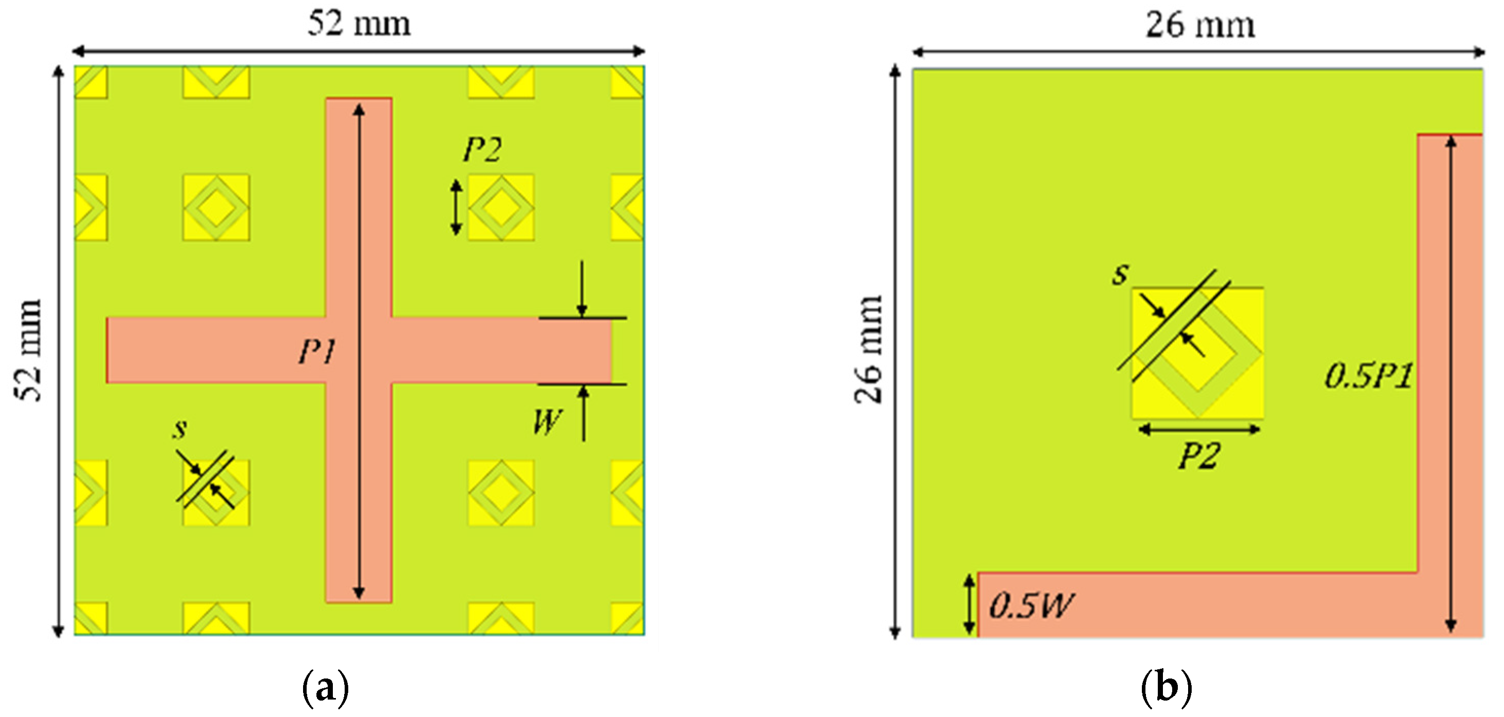
The proposed unit cell, designed for robust dual-band operation and depicted in Figure 1, ingeniously integrates two physically distinct resonant elements onto a single Rogers RO3003 substrate. The substrate is specified by a dielectric constant , a loss tangent which, it must be noted, is the manufacturer-provided value measured at 10 GHz, and a thickness h = 1.52 mm. In the visualization, both radiating elements (for S-band and X-band) are made of 0.5 oz-thick copper. The S-band element is shown in red, and the X-band element in yellow, while the green area indicates the dielectric substrate. The selection of this specific substrate was a deliberate engineering choice; its low dielectric loss is critical for minimizing ohmic losses within the material, thereby maximizing the antenna’s overall radiation efficiency. Simultaneously, its substantial thickness of 1.52 mm, which is equal to 0.01 λ0 for S-band and 0.04 λ0 for X-band, provides the necessary mechanical rigidity to maintain planarity across a large aperture, which is essential for preventing phase errors and ensuring the structural integrity of the antenna during launch and in-orbit operation.
Figure 1.
Configuration of the proposed unit-cell for (a) S-band and (b) X-band GHz.
The S-band radiator is realized as a classic cross-dipole patch, a structure well-suited for this frequency range, with a unit cell periodicity of 52 mm. This dimension corresponds to approximately 0.35 λ0 at the S-band center frequency of 2.0 GHz, a spacing chosen to prevent the emergence of grating lobes in the visible space. The reflection phase at this frequency is precisely and independently controlled by systematically varying the resonant length, P1, of the cross-dipole arms. For the X-band, functionality is achieved through a more intricate arrangement of four diamond-ring slotted patches that encircle the central cross-dipole. These elements are arranged with a much smaller periodicity of 13 mm, equivalent to approximately 0.35 λ0 at the X-band center frequency of 8.0 GHz.
This diamond-ring geometry, an evolution of our prior work, was specifically selected for its inherent capability to provide an exceptionally broad and linear phase response. This linearity is a critical attribute for minimizing phase quantization errors across the array, which in turn leads to higher gain and lower sidelobe levels.
The slot width, s, is intricately coupled to the patch length P2 through the empirical relationship defined in Equation (1), which was derived from extensive parametric simulations to optimize performance.
From a fundamental electromagnetic perspective, achieving a high degree of band isolation is the most critical challenge in any shared-aperture design, and the proposed configuration accomplishes this with remarkable elegance through a clever exploitation of geometric scale and impedance mismatch.
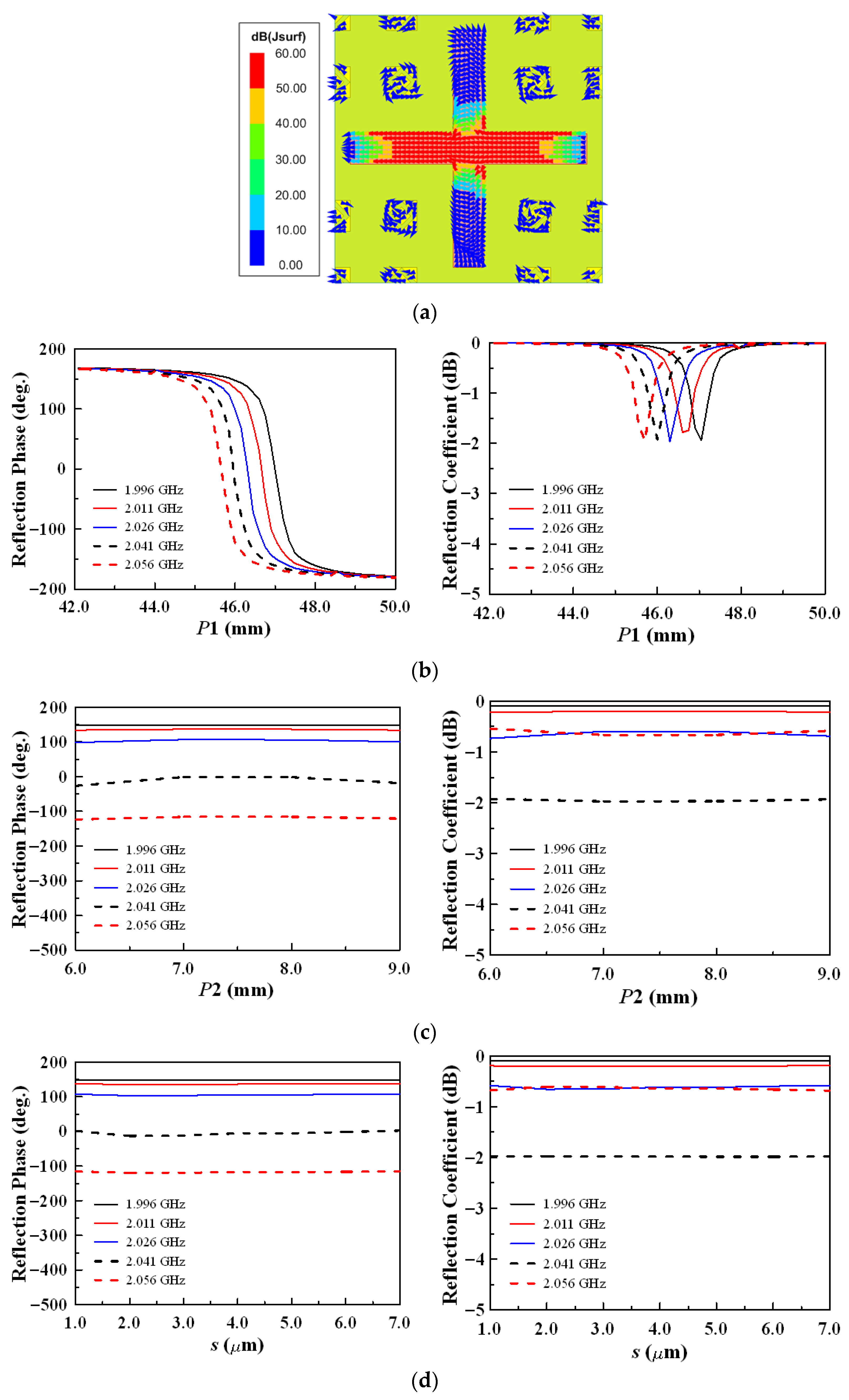
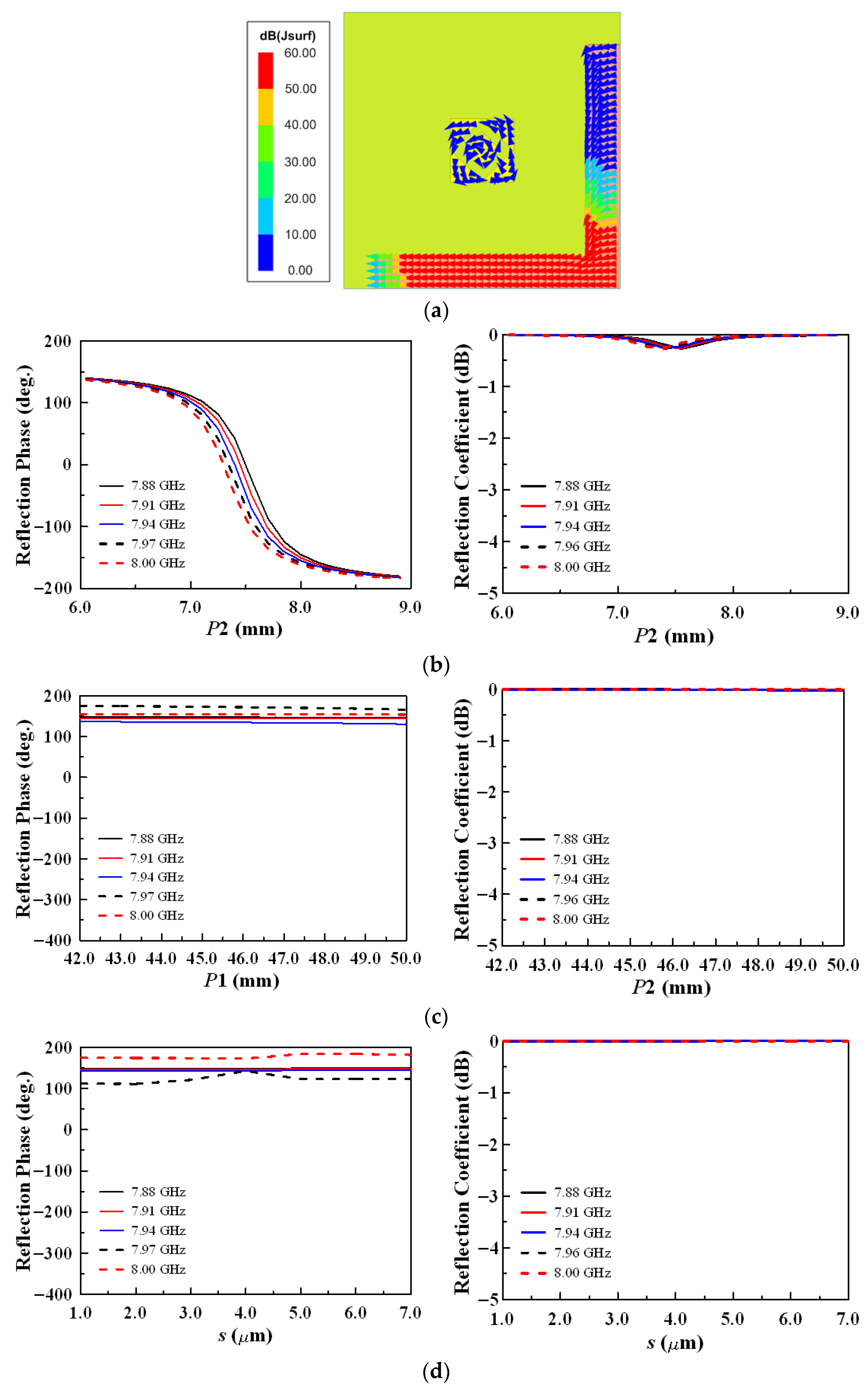
The simulated surface current distributions, vividly illustrated in Figure 2a and Figure 3a, provide compelling visual evidence of this effective decoupling. At the S-band frequency of 2.0 GHz, the X-band diamond-ring elements are electrically diminutive, with physical dimensions corresponding to only about λS-Band/12. This small electrical size ensures they are far from resonance, presenting a very high impedance to the incident electromagnetic field. This high-impedance state effectively creates an open-circuit condition, which minimizes the induction of currents on the X-band elements and renders them electromagnetically “invisible” to the S-band waves. Conversely, at the much higher X-band frequency of 8.0 GHz, the S-band cross-dipole becomes electrically large, approximately 1.4 λX-Band in size. In this state, it operates far from its fundamental resonance, resulting in a significant impedance mismatch that effectively precludes any efficient energy coupling from the incident X-band field. This inherent, passive isolation mechanism is the cornerstone of the design, allowing for the completely independent phase tuning of each band. Consequently, the S-band phase is governed exclusively by the length P1 of the cross-dipole, while the X-band phase is controlled solely by the dimensions (P2 and s) of the diamond-ring slots.
Figure 2.
Simulated results: (a) Surface current distribution, reflection phase response, and reflection magnitude response for (b) P1 variation, (c) P2 variation, and (d) s variation at S-band unit-cell.
Figure 3.
Simulated results: (a) Surface current distribution, reflection phase response, and reflection magnitude response for (b) P2 variation, (c) P1 variation, and (d) s variation at X-band unit-cell.
As comprehensively demonstrated by the simulation results in Figure 2 and Figure 3, the unit cell exhibits excellent reflection characteristics across both operational bands. At the S-band frequency of 1.996 GHz, a substantial reflection phase range of 321.92° is achieved, with a corresponding reflection loss that remains below 1.93 dB across the entire tuning range. This indicates that over 64% of the incident power is reflected efficiently. At the X-band frequency of 7.94 GHz, the performance approaches an almost lossless condition, with a minimal reflection loss of only 0.27 dB (meaning over 94% of the power is reflected) and a phase range that comfortably exceeds 320°. This near-complete phase coverage in both bands is a crucial prerequisite for accurate beamforming, as it allows the array to precisely shape the wavefront with minimal quantization loss, thereby maximizing the achievable gain. It is important to emphasize that this wide phase range is not an artifact of inter-band coupling but stems directly from the intrinsic resonant properties of each distinct radiating structure. This confirms the robustness and efficacy of the design strategy, which successfully achieves independent and comprehensive phase control without resorting to a more complex, costly, and less reliable multilayer architecture.
3. Reflectarray System Design and Measurement
3.1. Feed Antenna Design
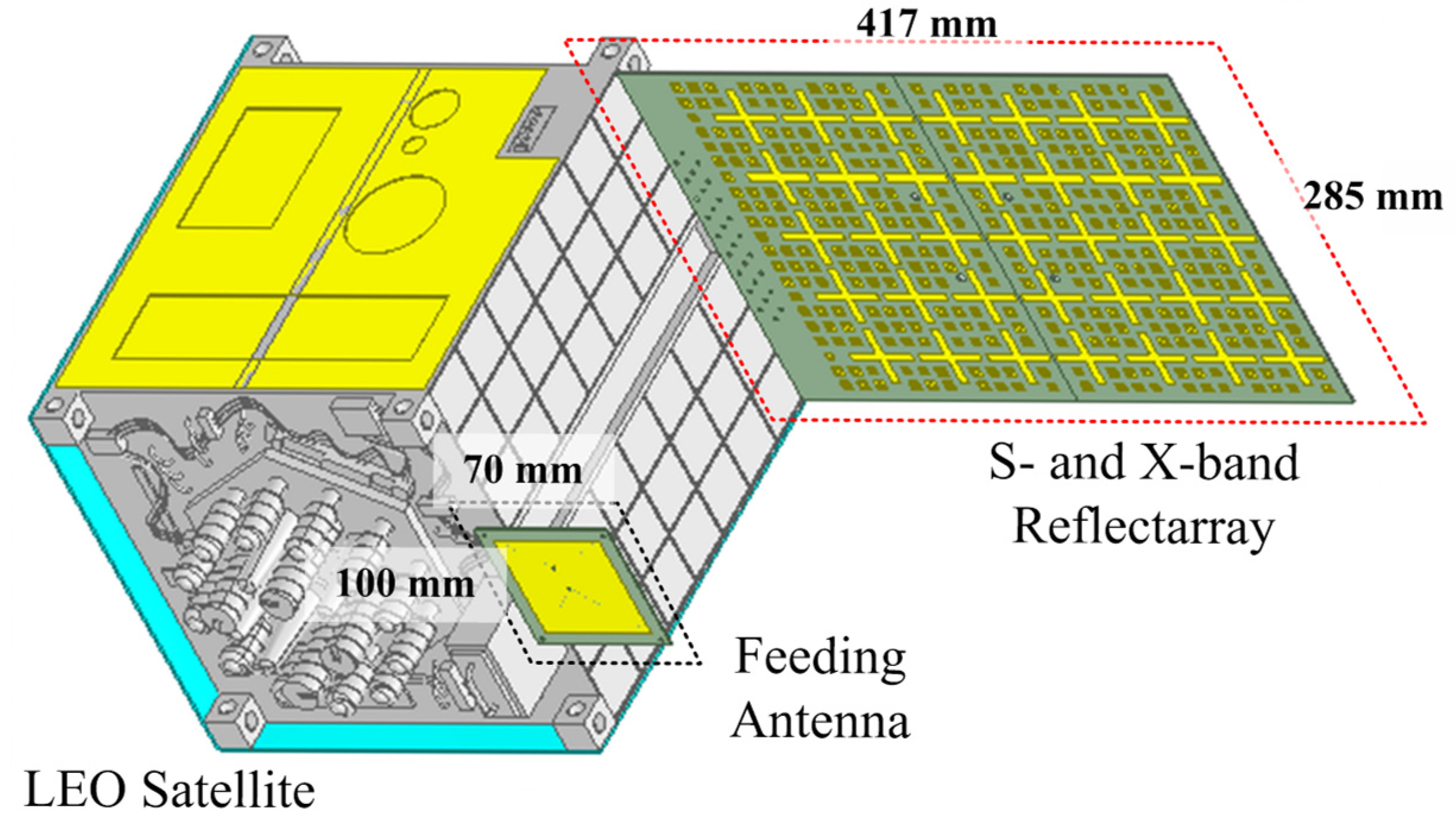
The complete reflectarray system, illustrated schematically in the overview of Figure 4, is an integrated assembly comprising two primary components: the large, planar reflecting surface populated with the unit cells described previously, and an offset dual-band microstrip patch antenna that serves as the illuminating feed.
Figure 4.
System overview of the proposed reflectarray antenna.
The selection of a microstrip patch feed is particularly advantageous for LEO satellite applications, as it inherently maintains a low profile and is exceptionally lightweight. This design choice stands in stark contrast to traditionally bulky and heavy horn antennas, which are often impractical for the stringent mass and volume constraints of modern satellite platforms. The use of a planar feed contributes significantly to the overall compactness and reduced mass of the entire antenna system.
The feed antenna is precisely positioned at the focal point of the reflectarray with a focal length (F) of 190 mm. To eliminate the detrimental effects of feed blockage, which can severely degrade gain and increase sidelobe levels, an offset configuration is employed. The feed is displaced by 118.6 mm from the geometric center of the aperture. The tilt and offset distance were optimized to achieve an illumination taper of approximately 10-dB at the aperture edges. The resulting radiation pattern asymmetry and elevated SLL observed in Section 4.1 are an intentional engineering trade-off resulting from this offset-feed configuration, which is necessary to eliminate aperture blockage for high-reliability LEO applications.
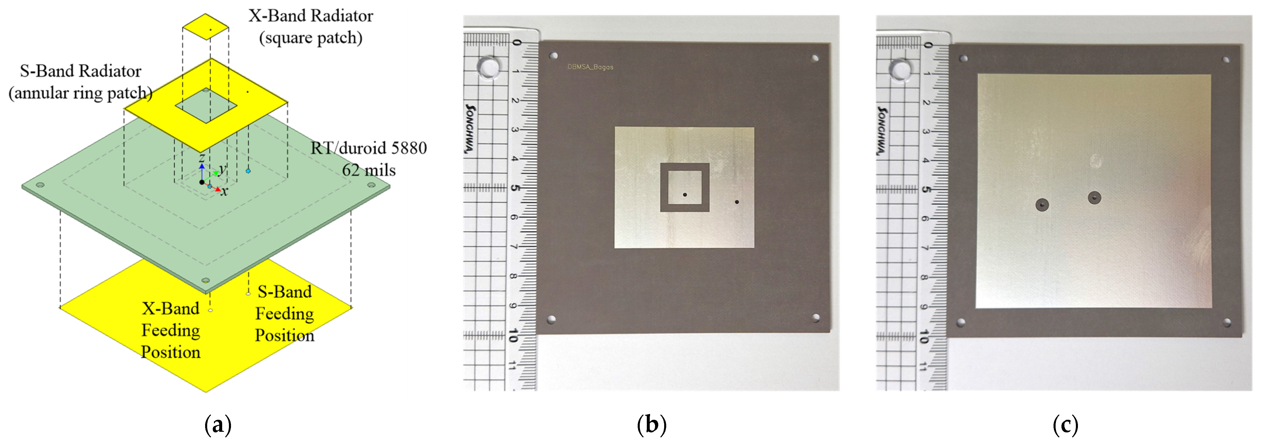
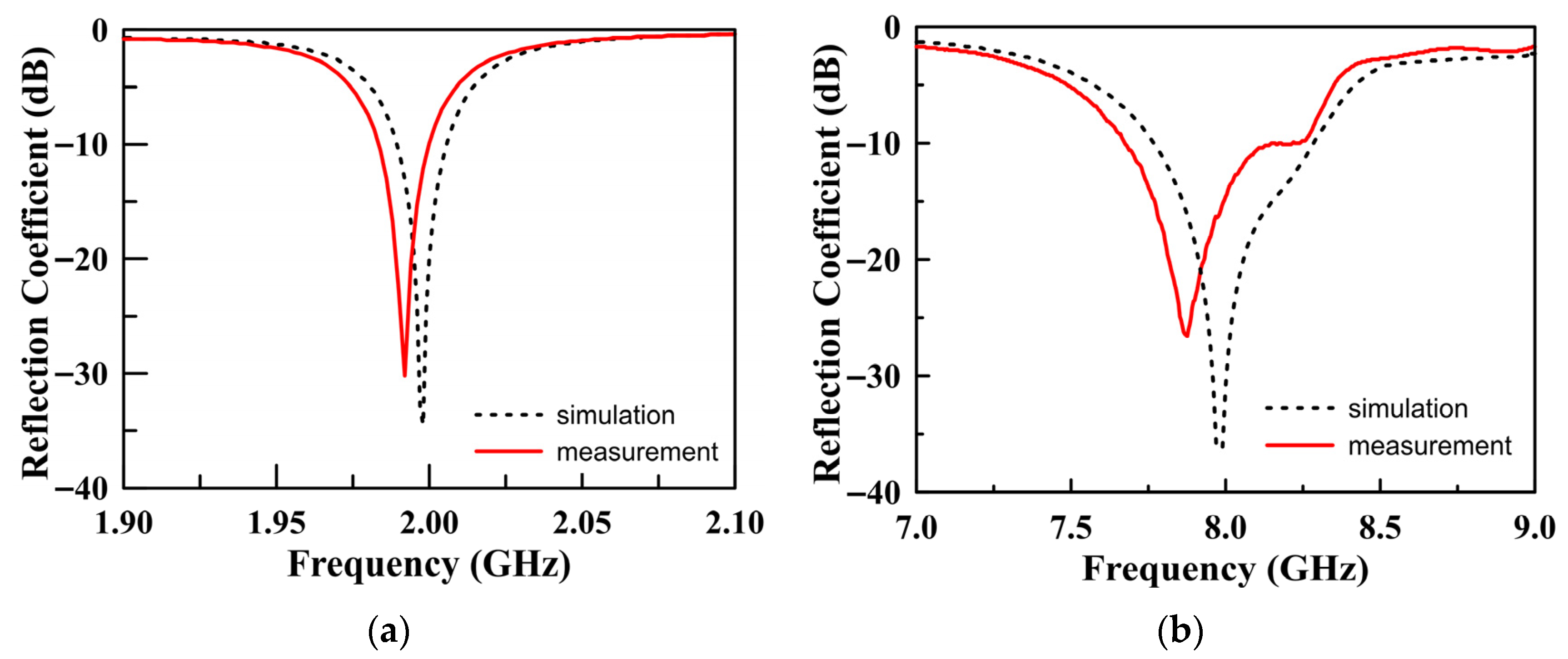
This specific angle directs the peak of the feed’s radiation pattern towards the center of the reflectarray, maximizing the energy captured by the aperture and minimizing spillover loss. The meticulously designed and subsequently fabricated feed antenna is shown in detail in Figure 5. A thorough performance characterization of the feed, presented in Figure 6, confirms its excellent dual-band operational capabilities. The measured impedance bandwidths, defined by the condition ∣S11∣ < −10 dB, comfortably cover the required frequency ranges of 1.98–2.00 GHz for the S-band and 7.67–8.24 GHz for the X-band. The usable frequency range is approximately 1% for the S-band and 7.2% for the X-band. The narrow bandwidth is an inherent limitation of using single-resonance unit cells, a necessary trade-off for achieving the 4:1 ratio on a single layer. However, this 1% bandwidth may be expanded using a horn-type wideband feed structure for low-data-rate Telemetry and Telecommand (TT&C) links.
Figure 5.
Dual-band feed antenna: (a) 3D prospective view, (b) top view photo of the implemented feed antenna, and (c) bottom view photo of the implemented feed antenna.
Figure 6.
Reflection coefficients of the feed microstrip antenna; (a) S-Band and (b) X-band.
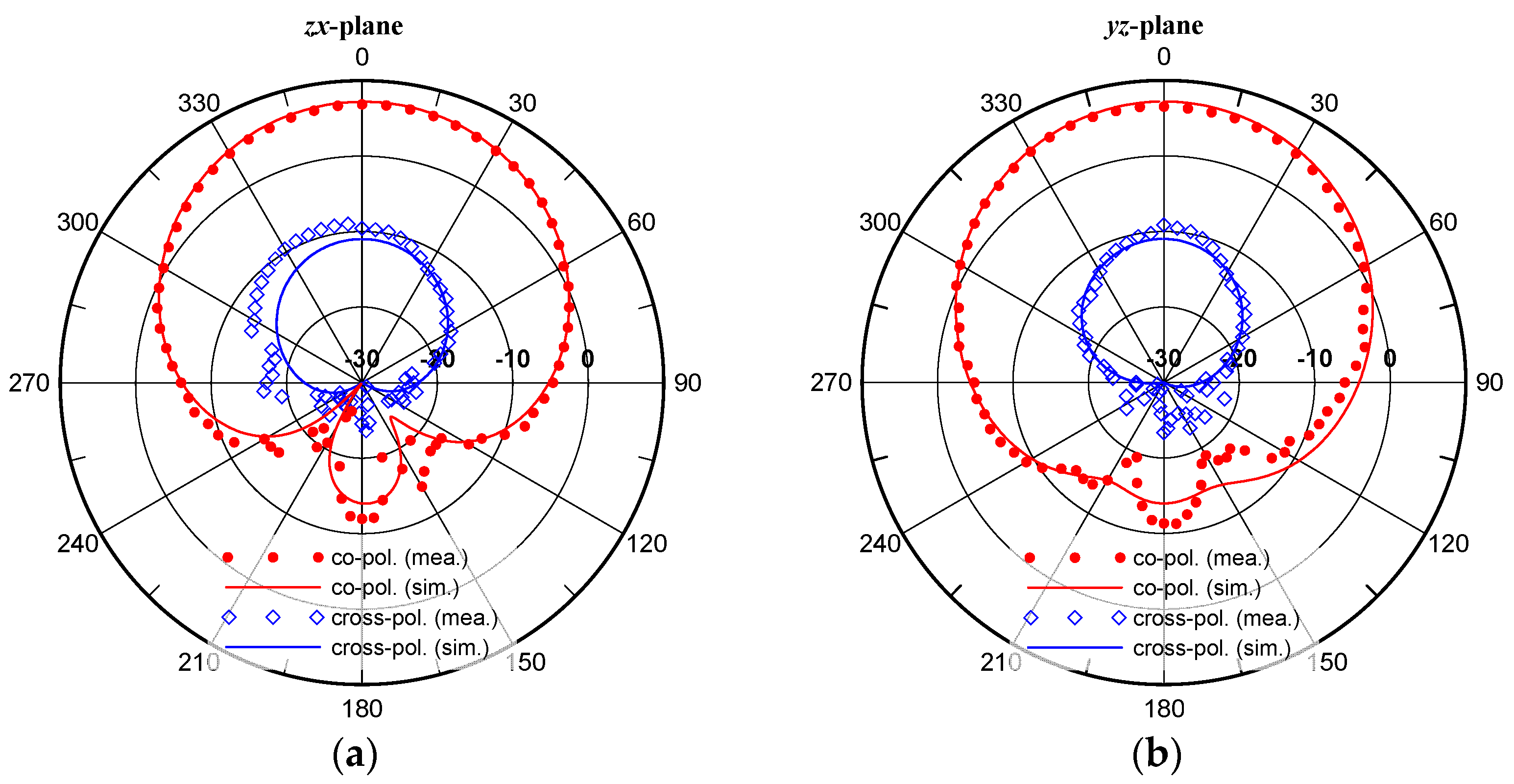
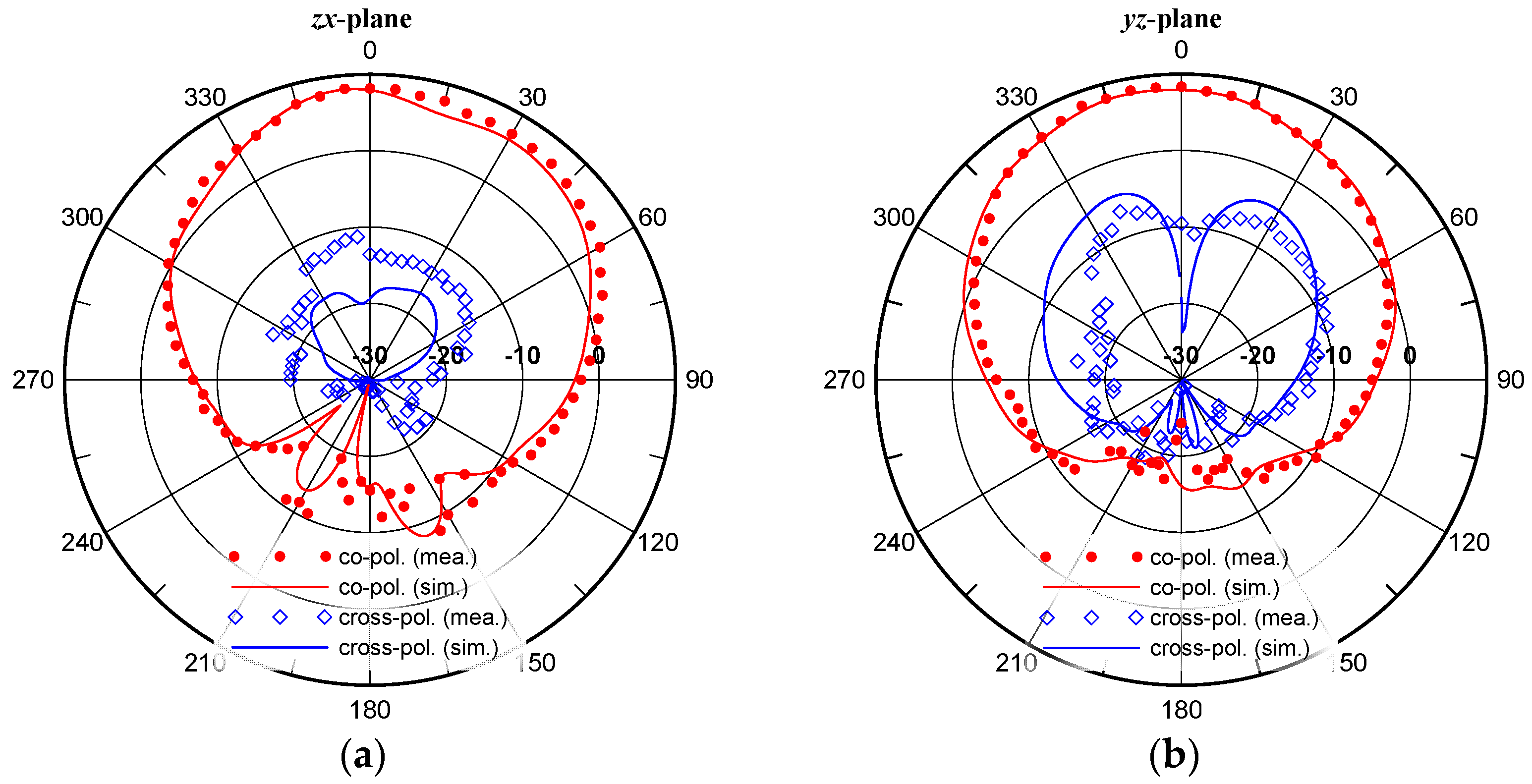
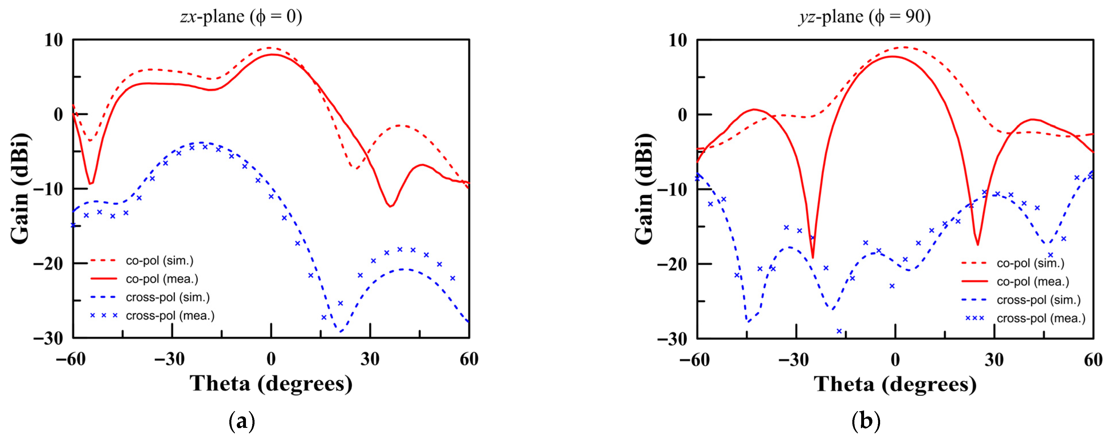
Furthermore, the simulated and measured radiation patterns, compared in Figure 7 and Figure 8, exhibit a half-power beamwidth (HPBW) of 76.7° at 1.996 GHz and 101.2° at 7.94 GHz. These beamwidths are well-suited to provide appropriate illumination across the entire reflectarray surface, tapering the field at the edges to reduce sidelobes while maintaining high aperture efficiency. The exceptionally strong correlation observed between the simulated predictions and the measured data serves to validate the accuracy of the feed antenna design and its fabrication process. The simulated and measured radiation patterns in Figure 7 and Figure 8 show a half-power beamwidth (HPBW) of 76.7° at 1.996 GHz and 101.2° at 7.94 GHz. The strong correlation between simulated and measured data validates the feed antenna design.
Figure 7.
Radiation pattern of the feed microstrip antenna at S-band of 1.996 GHz: (a) zx-plane, (b) yz-plane.
Figure 8.
Radiation pattern of the feed microstrip antenna at X-band of 7.94 GHz: (a) zx-plane, (b) yz-plane.
3.2. Reflectarray Design and Fabrication
To generate a highly collimated beam directed normal to the aperture plane (i.e., broadside radiation at (θ0 = 0°, ϕ0 = 0°), the required phase shift, ϕRA, imparted by each individual unit cell at its specific position (xi, yi) must precisely compensate for the spatial phase delay incurred by the wave traveling from the feed antenna. This compensatory phase is calculated for every element across the array using the standard reflectarray phase equation, a cornerstone of reflectarray theory:
In this fundamental equation, k0 represents the free-space wave number (2π/λ0), and Ri is the physical distance from the feed’s phase center to the center of the i-th element on the array surface. For the specific case of a broadside beam where the desired pointing angle θ0 is 0°, the equation simplifies considerably to ϕRA (xi, yi) = k0 Ri.
The resulting continuous phase distributions required for both the S- and X-bands are calculated using this formula and are then mapped to the corresponding physical unit-cell dimensions (P1 for S-band and P2 for X-band) based on the pre-calculated phase response curves shown in Figure 2 and Figure 3. This mapping process effectively translates the required phase shift at each point into a specific geometric structure.
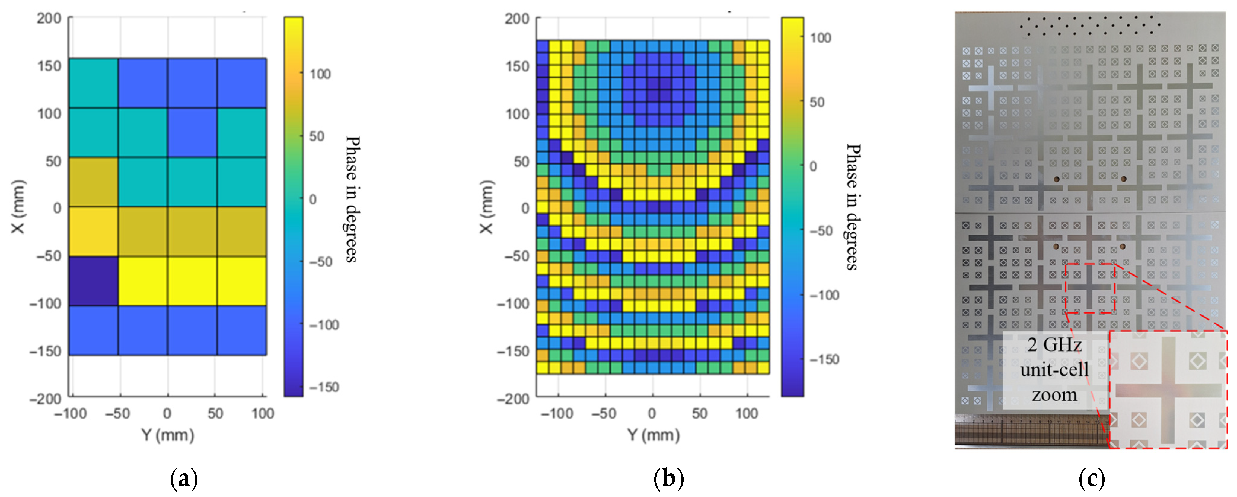
The final, quantized phase distributions across the entire aperture are visualized in Figure 9a,b. The complete reflectarray prototype, with overall physical dimensions of 260 × 364 mm2, was fabricated using standard printed circuit board (PCB) photolithography and etching techniques on the selected Rogers RO3003 substrate, as shown in the photograph in Figure 9c. The final array comprises a total of 35 elements (arranged in a 5 × 7 grid) for the S-band and a much denser grid of 341 elements for the X-band, reflecting the different wavelengths.
Figure 9.
Phase distribution of the proposed dual-band reflectarray antenna for (a) S-band and (b) X-band, and (c) top side photograph of the fabricated reflectarray surface.
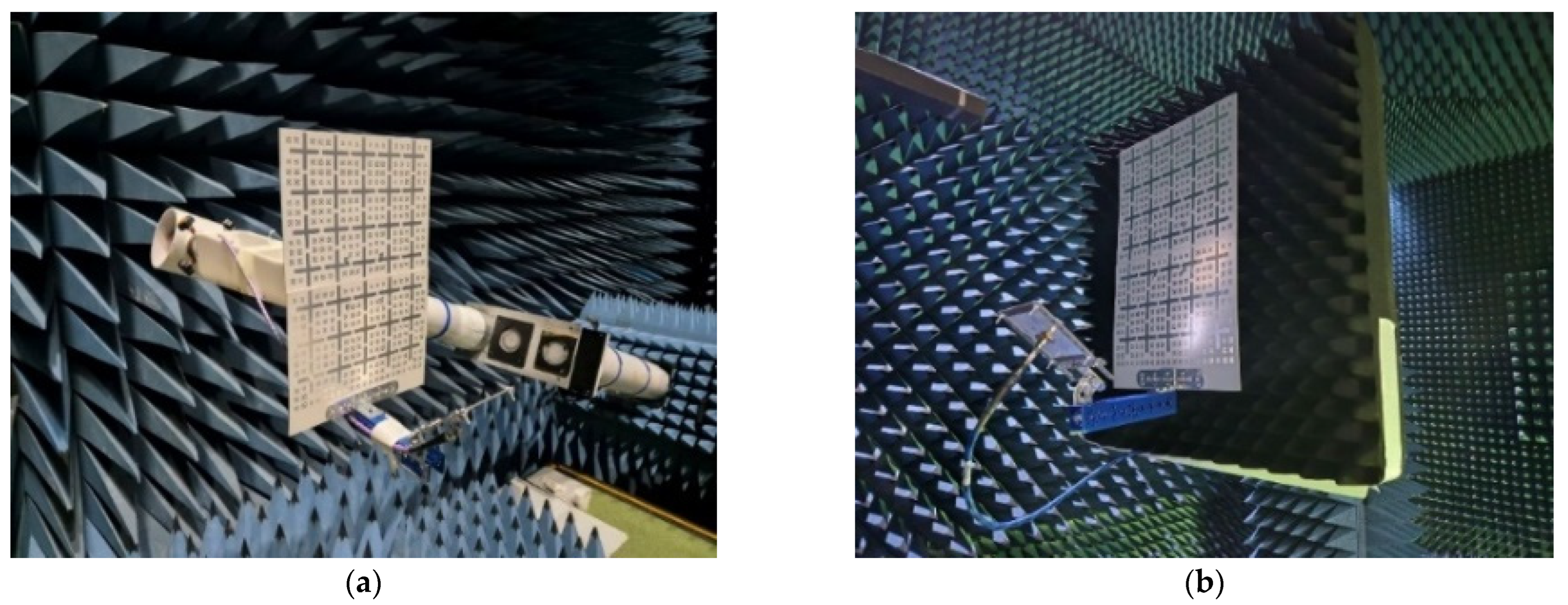
To experimentally verify the performance of the fabricated antenna, its radiation characteristics were meticulously measured in a far-field anechoic chamber. This specialized facility, depicted in Figure 10, is designed to absorb electromagnetic reflections, thereby simulating a free-space environment and enabling highly accurate measurements of the antenna’s radiation patterns and gain without interference from the surroundings.
Figure 10.
Fabricated reflectarray antenna and measurement test set-up for (a) S-band and (b) X-band.
4. Results and Discussion
4.1. Radiation Pattern Measurements
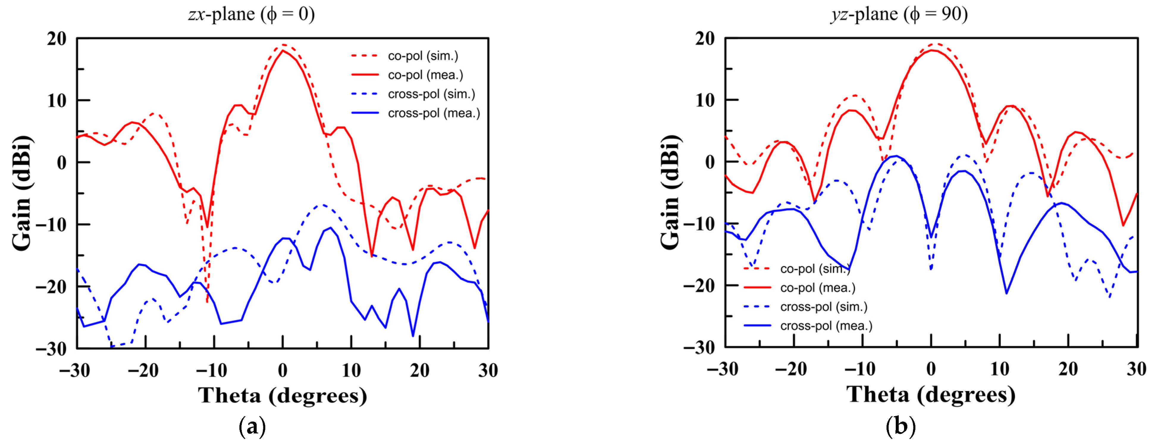
The measured and simulated far-field radiation patterns, which are fundamental indicators of antenna performance, are presented for direct comparison in Figure 11 and Figure 12. At the S-band center frequency of 1.996 GHz, the antenna achieved a measured peak gain of 7.99 dBi, with a corresponding half-power beamwidth (HPBW) in the yz-plane of 22.86°. This experimental result compares reasonably well with the simulated prediction, which anticipated a slightly higher gain of 8.83 dBi and a wider HPBW of 26.11°. The minor discrepancies are attributable to the factors that will be discussed in the loss budget analysis. At the X-band center frequency of 7.94 GHz, the antenna’s performance is significantly more directive due to the larger electrical aperture.
Figure 11.
Radiation patterns of the proposed antenna at 1.996 GHz for (a) zx-plane and (b) yz-plane.
Figure 12.
Radiation patterns of the proposed antenna at 7.94 GHz for (a) zx-plane and (b) yz-plane.
The measured gain was a substantial 17.99 dBi, with a narrow HPBW of 6.71° and a commendable side lobe level (SLL) of −13.42 dB relative to the main beam.
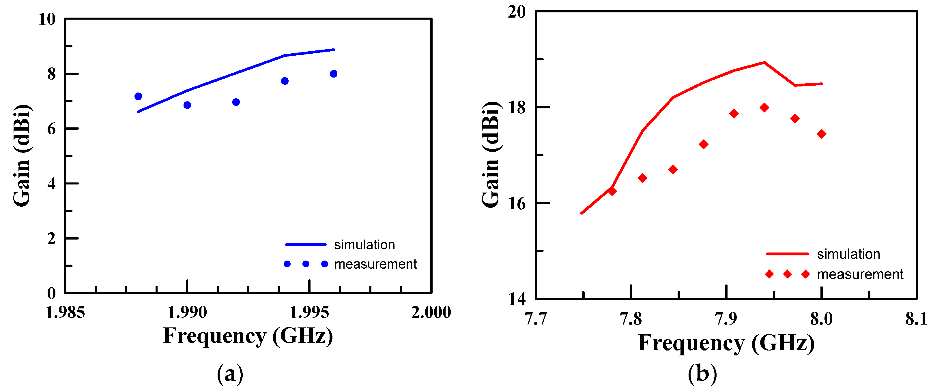
These results are in strong agreement with the simulated performance, which predicted a gain of 18.93 dBi and an HPBW of 6.61°. The gain as a function of frequency across both operating bands is plotted in Figure 13. This data clearly confirms that the antenna’s performance is optimized around the intended design center frequencies, with gain values peaking as expected.
Figure 13.
Antenna gain over the operating frequency for (a) S-band and (b) X-band.
4.2. Discussion and Performance Comparison
The experimental results validate the dual-band functionality of the proposed single-layer reflectarray. A critical analysis of these results in the context of existing literature highlights the novelty and practical advantages of our approach.
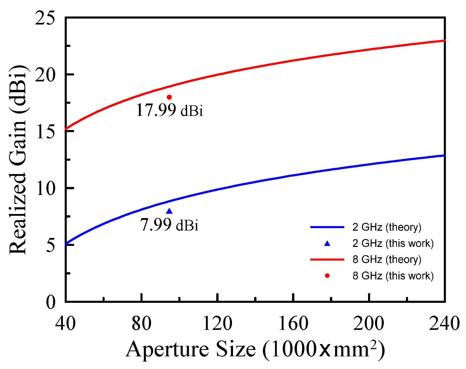
Table 1 provides a direct comparison of key structural and operational parameters with other dual-band reflectarray designs. It is important to note that a direct comparison of gain values can be misleading, as gain is inherently linked to the electrical size of the aperture, as shown in Figure 14.
Table 1.
Performance Comparison of Dual-Band Reflectarray Antennas.
Figure 14.
Aperture size impacts the antenna gain.
To provide a more objective performance metric that normalizes the gain to the physical size, the Aperture Efficiency () was calculated for both bands:
where is measured realized gain, A is the physical aperture area, and λ0 is the free-space wavelength at the center frequency. The calculated aperture efficiencies are 18.4% for the S-band and 39.7% for the X-band.
As shown in Table 1, the principal innovation of this work is clearly highlighted: achieving a record-breaking frequency ratio of 4.00 on a simple, single-layer structure. Our X-band aperture efficiency of 39.7% is considered highly competitive when benchmarked specifically against other single-layer designs, particularly given the severe 4:1 ratio. This is a significant leap compared to other single-layer designs, which typically operate with frequency ratios around 2.2 or less. Even complex double-layer structures, such as the one presented by [], achieve a much smaller frequency ratio of 1.50. While other works report higher gain values, they do so with significantly larger electrical apertures. For instance, the design by [] has an aperture diameter of 9.7 λlow, whereas our design has a much more compact aperture of 1.7 × 2.4 λlow. The lower gain of our antenna is a direct consequence of this smaller electrical size. Furthermore, when compared to multilayer structures in [], which achieve high gain at the cost of increased mass, complexity, and the critical risk of delamination in a space environment, the advantage of our approach for LEO applications becomes evident.
Furthermore, a consistent discrepancy of approximately 1 dB exists between simulated and measured gain across both bands. This difference is not negligible and can be attributed to a combination of real-world factors that are not fully captured in the simulation.
5. Conclusions
This paper has successfully presented the comprehensive design, meticulous fabrication, and thorough experimental measurement of a novel dual-band, single-layer reflectarray antenna operating concurrently at S- and X-bands, specifically tailored for the demanding requirements of modern LEO satellite applications. By employing an innovative shared-aperture unit cell that integrates electromagnetically isolated resonant elements, fully independent and precise phase control for each frequency band was successfully achieved on a single, monolithic substrate. The key and most significant achievement of this work is the unambiguous demonstration of a very high frequency ratio (4:1) within a remarkably simple, low-profile, and planar architecture. This accomplishment directly addresses the critical and persistent need for highly reliable, lightweight, and mass-producible antenna components within the rapidly expanding LEO satellite industry.
The fabricated prototype, constructed on a standard 1.52 mm thick Rogers RO3003 substrate, yielded a measured peak gain of 7.99 dBi at 1.996 GHz and 17.99 dBi at 7.94 GHz, results that align well with theoretical predictions once real-world loss mechanisms are considered. The subsequent analysis of aperture efficiency and a detailed loss budget provided a comprehensive and transparent understanding of the antenna’s real-world performance characteristics and limitations. Ultimately, the profound structural simplicity of the proposed reflectarray, which eliminates the delamination risk and significantly reduces the manufacturing complexity and cost associated with multilayer designs, establishes it as a viable, compelling, and highly promising candidate for the next generation of cost-effective, low-profile antenna systems in advanced LEO satellite communication networks. This work paves the way for more scalable and robust satellite hardware, facilitating the continued growth of global connectivity.
Author Contributions
Conceptualization, T.-H.L. and S.P.; Methodology, B.S., T.-H.L. and S.P.; Software, S.P.; Validation, B.S., T.-H.L. and S.P.; Formal analysis, B.S.; Investigation, T.-H.L. and S.P.; Resources, S.P.; Data curation, B.S.; Writing—original draft, B.S. and S.S.; Writing—review & editing, S.S., T.-H.L. and S.P.; Visualization, S.P.; Supervision, S.P.; Project administration, S.P.; Funding acquisition, S.P. All authors have read and agreed to the published version of the manuscript.
Funding
This research was supported by the Korea Research Institute for defense Technology planning and Advancement (KRIT) grant funded by the Korea government, DAPA (Defense Acquisition Program Administration) (KRIT-CT-22-047), and was also supported by the National Research Foundation of Korea (NRF) grant funded by the Korea government (MSIT) (RS-2025-00556690).
Institutional Review Board Statement
Not applicable.
Informed Consent Statement
Not applicable.
Data Availability Statement
The original contributions presented in this study are included in the article. Further inquiries can be directed to the corresponding author.
Conflicts of Interest
The authors declare no conflict of interest.
References
- Hong, Y.P.; Kim, J.M.; Jeong, S.C.; Kim, D.H.; Choi, M.H.; Lee, Y.; Yook, J.G. S-band dual-path dual-polarized antenna system for satellite digital audio radio service (SDARS) application. IEEE Trans. Microw. Theory Tech. 2006, 54, 1569–1575. [Google Scholar] [CrossRef]
- Choi, E.C.; Lee, J.W.; Lee, T.K.; Lee, W.K. Circularly polarized S-band satellite antenna with parasitic elements and its arrays. IEEE Antennas Wirel. Propag. Lett. 2014, 13, 1689–1692. [Google Scholar] [CrossRef]
- Elahi, M.; Trinh-Van, S.; Yang, Y.; Lee, K.-Y.; Hwang, K.-C. Compact and High Gain 4 × 4 Circularly Polarized Microstrip Patch Antenna Array for Next Generation Small Satellite. Appl. Sci. 2021, 11, 8869. [Google Scholar] [CrossRef]
- Tayyab, U.; Kumar, A.; Petry, H.-P.; Asghar, M.E.; Hein, M.A. Dual-Band Nested Circularly Polarized Antenna Array for 5G Automotive Satellite Communications. Appl. Sci. 2023, 13, 11915. [Google Scholar] [CrossRef]
- Pavone, S.C.; Mauro, G.S.; Donato, L.D.; Sorbello, G. Design of Dual Circularly Polarized Sequentially-Fed Patch Antennas for Satellite Applications. Appl. Sci. 2020, 10, 2107. [Google Scholar] [CrossRef]
- J, A.J.; Palaniswamy, S.K.; Kumar, S.; Kanagasabai, M.; Matekovits, L. Design and analysis of wideband single-layer reflectarray antenna for remote sensing and environmental monitoring. Sensors 2025, 25, 954. [Google Scholar] [CrossRef] [PubMed]
- Zhou, M.; Nicolaci, P.G.; Marote, D.; Herreros, J.; Vesterdal, N.; Palvig, M.F.; Sørensen, S.B.; Toso, G. High resolution synthetic aperture radar based on multiple reflectarray apertures. Electronics 2025, 14, 3832. [Google Scholar] [CrossRef]
- Kusnins, R.; Cirjulina, D.; Eidaks, J.; Gailis, K.; Babajans, R.; Litvinenko, A.; Kolosovs, D.; Pikulins, D. A study on a compact double layer sub-GHz reflectarray design suitable for wireless power transfer. Electronics 2024, 13, 2754. [Google Scholar] [CrossRef]
- Nascetti, A.; Pittella, E.; Teofilatto, P.; Pisa, S. High-gain S-band patch antenna system for earth-observation CubeSat satellites. IEEE Antennas Wirel. Propag. Lett. 2015, 14, 434–437. [Google Scholar] [CrossRef]
- Abdullah, H.H.; Elboushi, A.; Gohar, A.E.; Abdallah, E.A. An improved S-band CubeSat communication subsystem design and implementation. IEEE Access 2021, 9, 45123–45136. [Google Scholar] [CrossRef]
- Vazquez-Sogorb, C.; Montoya-Roca, R.; Addamo, G.; Peverini, O.A.; Virone, G. Ridged Apertures for LEO Direct Radiating Arrays in Ka-Band. Appl. Sci. 2024, 14, 7825. [Google Scholar] [CrossRef]
- Encinar, J.A.; Arrebola, M.; de la Fuente, L.F.; Toso, G. A transmit-receive reflectarray antenna for direct broadcast satellite applications. IEEE Trans. Antennas Propag. 2011, 59, 3255–3264. [Google Scholar] [CrossRef]
- Jung, E.Y.; Lee, J.W.; Lee, T.K.; Lee, W.K. SIW-based array antennas with sequential feeding for X-band satellite communication. IEEE Trans. Antennas Propag. 2012, 60, 3632–3639. [Google Scholar] [CrossRef]
- Rengarajan, S.R. Reflectarrays of rectangular microstrip patches for dual-polarization dual-beam radar interferometers. Prog. Electromagn. Res. 2013, 133, 1–15. [Google Scholar] [CrossRef]
- Anim, K.; Shin, G.H.; Jung, Y.B. Dual-resonant stacked linear array of cross-slotted patches for small SAR satellites. IEEE Trans. Antennas Propag. 2021, 69, 3584–3587. [Google Scholar] [CrossRef]
- Herraiz Tirado, D.; Fernandez, M.D.; Herraiz-Zanon, D.; Carballo, I.G.; Alomainy, A.; Belenguer, A. Innovative Integration of High-Performance Floating Patch Antennas in Empty Substrate Integrated Waveguides. Appl. Sci. 2025, 15, 4549. [Google Scholar] [CrossRef]
- Rao, S.K. Advanced antenna technologies for satellite communications payloads. IEEE Trans. Antennas Propag. 2015, 63, 1205–1217. [Google Scholar] [CrossRef]
- Rebollo, A.; Vaquero, Á.F.; Arrebola, M.; Pino, M.R. 3D-printed dual-reflector antenna with self-supported dielectric subreflector. IEEE Access 2020, 8, 209091–209100. [Google Scholar] [CrossRef]
- Osaretin, I.A.; Shields, M.W.; Lorenzo, J.A.M.; Blackwell, W.J. A compact 118-GHz radiometer antenna for the micro-sized microwave atmospheric satellite. IEEE Antennas Wirel. Propag. Lett. 2014, 13, 1533–1536. [Google Scholar] [CrossRef]
- Zhang, H.; Chen, X.; Wang, Z.; Ge, Y.; Pu, J. A 1-bit electronically reconfigurable reflectarray antenna in X band. IEEE Access 2019, 7, 66567–66575. [Google Scholar] [CrossRef]
- Yang, H.; Yang, F.; Cao, X.; Xu, S.; Gao, J.; Chen, X.; Li, M.; Li, T. A 1600-element dual-frequency electronically reconfigurable reflectarray at X/Ku-band. IEEE Trans. Antennas Propag. 2017, 65, 3024–3032. [Google Scholar] [CrossRef]
- Prado, D.R.; Lopez-Fernandez, J.A.; Barquero, G.; Arrebola, M.; Las-Heras, F. Fast and accurate modeling of dual-polarized reflectarray unit cells using support vector machines. IEEE Trans. Antennas Propag. 2018, 66, 1258–1270. [Google Scholar] [CrossRef]
- Kiris, O.; Topalli, K.; Unlu, M. A reflectarray antenna using hexagonal lattice with enhanced beam steering capability. IEEE Access 2019, 7, 45526–45532. [Google Scholar] [CrossRef]
- Yu, H.; Guo, L. Broadband single-layer reflectarray antenna employing circular ring elements dented with sectorial slits. IEEE Access 2019, 7, 165814–165819. [Google Scholar] [CrossRef]
- You, B.-Q.; Liu, Y.-X.; Zhou, J.-H.; Chou, H.-T. Numerical synthesis of dual-band reflectarray antenna for optimum near-field radiation. IEEE Antennas Wirel. Propag. Lett. 2012, 11, 760–762. [Google Scholar] [CrossRef]
- Lu, S.; Qu, S.-W. Low-profile dual-band reflector antenna for high-frequency applications. Sensors 2023, 23, 5781. [Google Scholar] [CrossRef]
- Khan, S.; Malik, B.T.; Koziel, S. Highly compact dual-band frequency selective surface for path-loss and coverage improvement in millimeter-wave advanced wireless applications. Sci. Rep. 2025, 15, 7029. [Google Scholar] [CrossRef] [PubMed]
- Guo, L.; Tan, P.K.; Chio, T.H. Single-layered broadband dual-band reflectarray with linear orthogonal polarizations. IEEE Trans. Antennas Propag. 2016, 64, 4064–4068. [Google Scholar] [CrossRef]
- Kong, G.; Li, X.; Wang, Q.; Zhang, J. A dual-band circularly polarized elliptical patch reflectarray antenna for high-power microwave applications. IEEE Access 2021, 9, 74522–74530. [Google Scholar] [CrossRef]
- Han, C.; Rodenbeck, C.; Huang, J.; Chang, K. A C/Ka dual frequency dual layer circularly polarized reflectarray antenna with microstrip ring elements. IEEE Trans. Antennas Propag. 2004, 52, 2871–2876. [Google Scholar] [CrossRef]
- Liu, Y.; Cheng, Y.J.; Zhao, M.H.; Fan, Y. Dual-band shared-aperture high-efficiency reflectarray antenna based on structure-reuse technique. IEEE Antennas Wirel. Propag. Lett. 2021, 20, 366–370. [Google Scholar] [CrossRef]
- Nayeri, P.; Yang, F.; Elsherbeni, A.Z. Reflectarray Antennas: Theory, Designs, and Applications; Wiley-IEEE Press: Piscataway, NJ, USA, 2018. [Google Scholar] [CrossRef]
- Huang, J.; Encinar, J.A. Reflectarray Antennas; John Wiley & Sons: Hoboken, NJ, USA, 2007; Volume 30. [Google Scholar] [CrossRef]
- Tienda, C.; Encinar, J.A.; Barba, M.; Arrebola, M. Dual-polarization Ku-band compact spaceborne antenna based on dual-reflectarray optics. Sensors 2018, 18, 1100. [Google Scholar] [CrossRef] [PubMed]
- Li, S.; Cai, Y.; Ma, H.; Bu, L.; Qi, S.; Cao, Y.; Wu, T. A novel broadband reflectarray antenna employing equivalent magnetic dipole elements. Sci. Rep. 2025, 15, 10771. [Google Scholar] [CrossRef]
- Satriyotomo, B.; Pyo, S. A reflectarray antenna based on diamond-ring slotted elements with enhanced reflection phase. In Proceedings of the 2022 IEEE International Conference on Aerospace Electronics and Remote Sensing Technology (ICARES), Yogyakarta, Indonesia, 26–27 October 2022; pp. 1–4. [Google Scholar] [CrossRef]
- Ajitesh; Srivastava, S.K.; Singh, A.; Bharati, R.; Sharma, A.K.; Meshram, M.K. A single layer dual band reflectarray antenna for millimeter-wave application. In Proceedings of the 2022 IEEE Microwave, Antennas and Propagation Conference (MAPCON), Bangalore, India, 12–15 December 2022. [Google Scholar] [CrossRef]
- Gülseren, A.H.; Alparslan, A.; Türker Tokan, N. Dual-Band Frequency Selective Surface-Backed Reflectarray for High-Speed Ka-Band Satellites. Appl. Sci. 2024, 14, 2928. [Google Scholar] [CrossRef]
- Pozar, D.M.; Targonski, S.D.; Syrigos, H.D. Design of millimeter wave microstrip reflectarrays. IEEE Trans. Antennas Propag. 1999, 45, 287–296. [Google Scholar] [CrossRef]
- Encinar, J.A. Design of two-layer printed reflectarrays using patches of variable size. IEEE Trans. Antennas Propag. 2001, 49, 1403–1410. [Google Scholar] [CrossRef]
- Chaharmir, M.R.; Shaker, J.; Cuhaci, M.; Ittipiboon, A. A Broadband Reflectarray Antenna With Double Square Rings As The Cell Elements. In Proceedings of the 2006 First European Conference on Antennas and Propagation, Nice, France, 6–10 November 2006; pp. 1–4. [Google Scholar] [CrossRef]
- Dores, G.; Dinis, H.; Baptista, D.; Mendes, P.M. Performance Assessment of a GNSS Antenna Array with Digital Beamforming Supported by an FPGA Platform. Appl. Sci. 2025, 15, 5811. [Google Scholar] [CrossRef]
- Malfajani, R.S.; Arand, B.A. Dual-band orthogonally polarized single-layer reflectarray antenna. IEEE Trans. Antennas Propag. 2017, 65, 6145–6150. [Google Scholar] [CrossRef]
- Li, X.; Li, X.; Yang, L. Single-layer dual-band wide band-ratio reflectarray with orthogonal linear polarization. IEEE Access 2020, 8, 93586–93593. [Google Scholar] [CrossRef]
- Su, T.; Yi, X.; Wu, B. X/Ku dual-band single-layer reflectarray antenna. IEEE Antennas Wirel. Propag. Lett. 2019, 18, 338–342. [Google Scholar] [CrossRef]
- Narayanasamy, K.; Alsath, M.G.; Savarimuthu, K. Design and Analysis of Single Layer Ku/K Band Integrated Element Reflectarray Antenna. Int. J. Microw. Wirel. Technol. 2023, 15, 1424–1433. [Google Scholar] [CrossRef]
- Costanzo, S.; Venneri, F.; Borgia, A.; Di Massa, G. Dual-band dual-linear polarization reflectarray for mmWaves/5G applications. IEEE Access 2020, 8, 78183–78192. [Google Scholar] [CrossRef]
- Yobuamalan, V.Y.; Subramaniam, R.; Kumar, S.S.S.; Sivathanu, C. Dual Band Reflect Array for Tx/Rx Ground Station Drone Tracking Applications. Inf. Midem-J. Microelectron. Electron. Compon. Mater. 2025, 55, 115–125. [Google Scholar] [CrossRef]
- Deng, R.; Yang, F.; Xu, S.; Li, M. An FSS-backed 20/30-GHz dual-band circularly polarized reflectarray with suppressed mutual coupling and enhanced performance. IEEE Trans. Antennas Propag. 2017, 65, 926–931. [Google Scholar] [CrossRef]
Disclaimer/Publisher’s Note: The statements, opinions and data contained in all publications are solely those of the individual author(s) and contributor(s) and not of MDPI and/or the editor(s). MDPI and/or the editor(s) disclaim responsibility for any injury to people or property resulting from any ideas, methods, instructions or products referred to in the content. |
© 2025 by the authors. Licensee MDPI, Basel, Switzerland. This article is an open access article distributed under the terms and conditions of the Creative Commons Attribution (CC BY) license (https://creativecommons.org/licenses/by/4.0/).