Research on In-Cylinder Pressure Monitoring Method of Diesel Engine Based on LSTM
Abstract
1. Introduction
2. Establishment of Diesel Engine Test Bench and One-Dimensional Simulation Model
3. Establishment of Diesel Engine In-Cylinder Pressure Monitoring Model
4. Experiment and Result Analysis
5. Conclusions
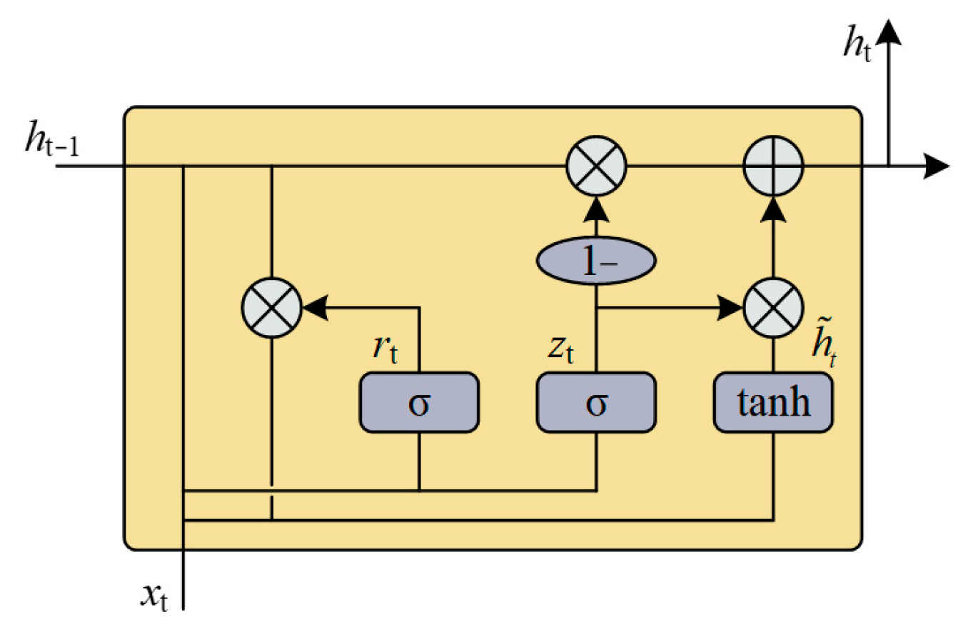
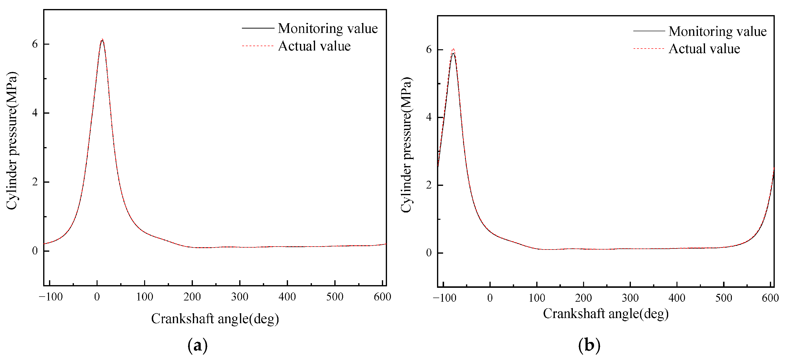
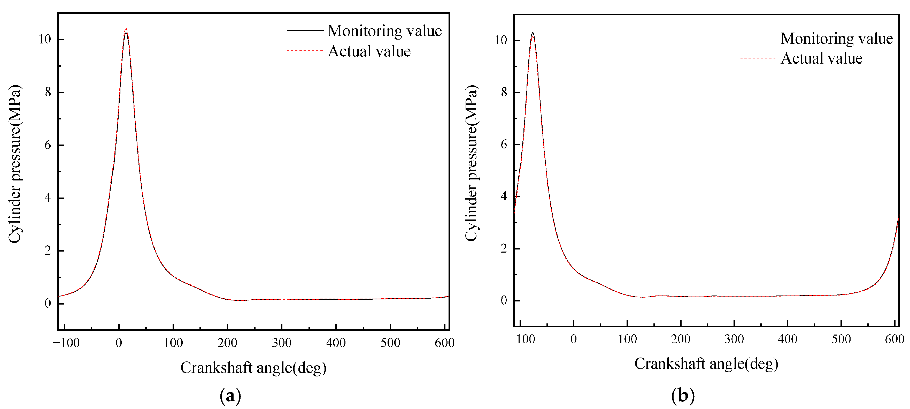
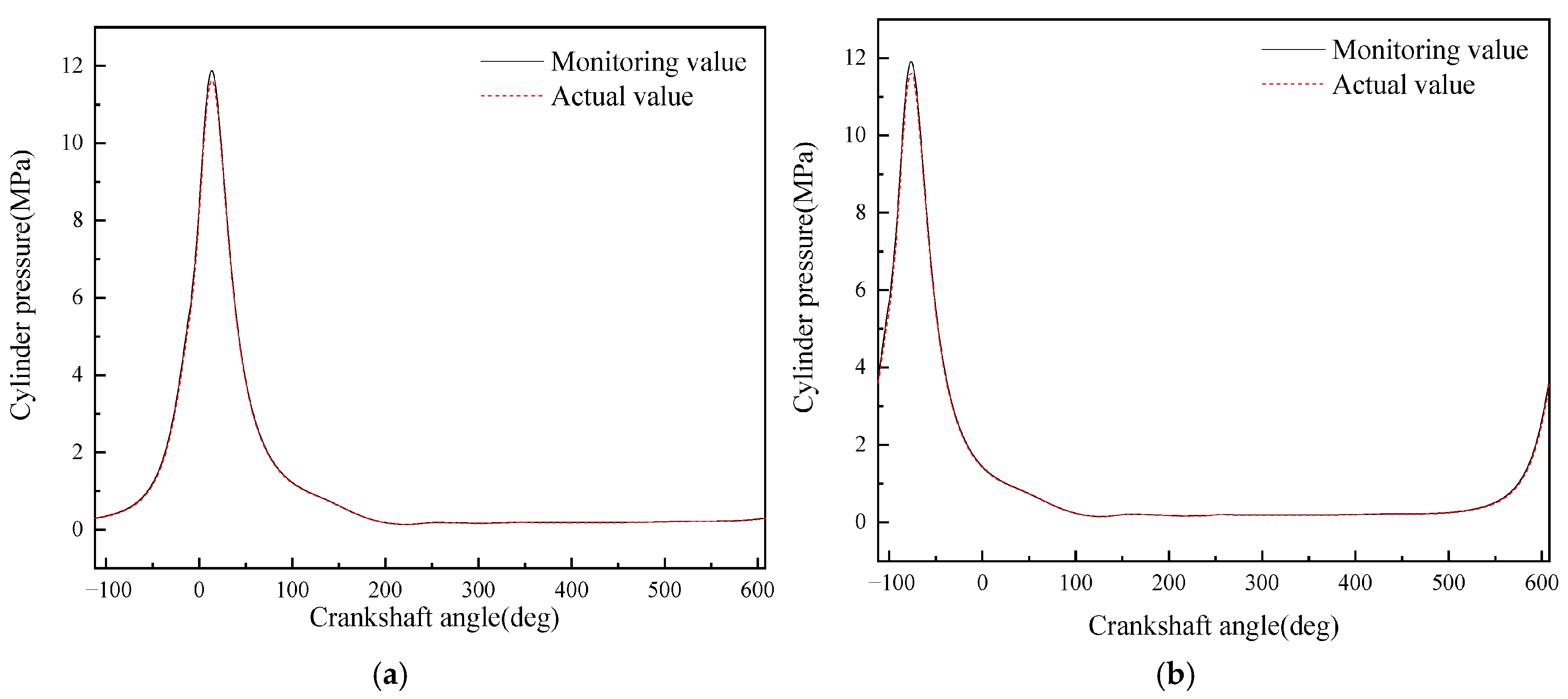
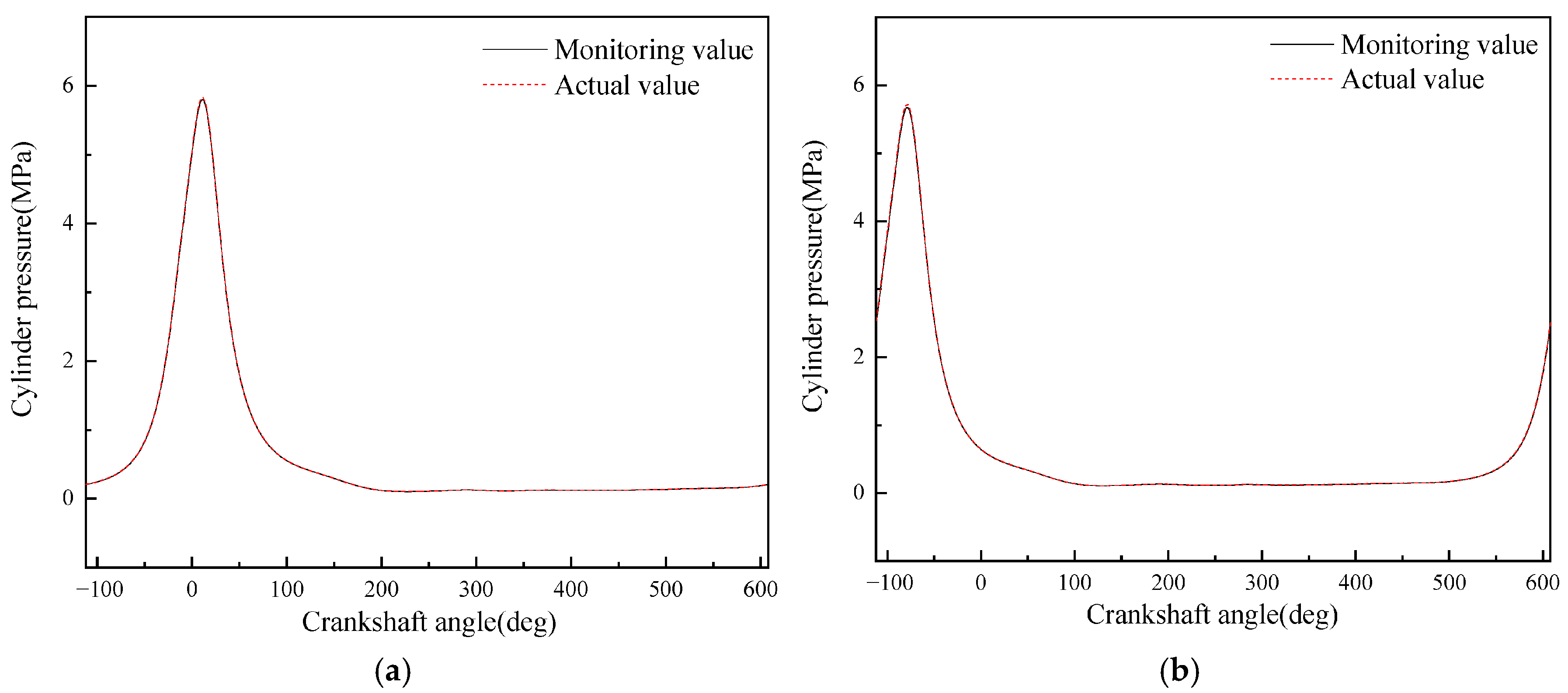
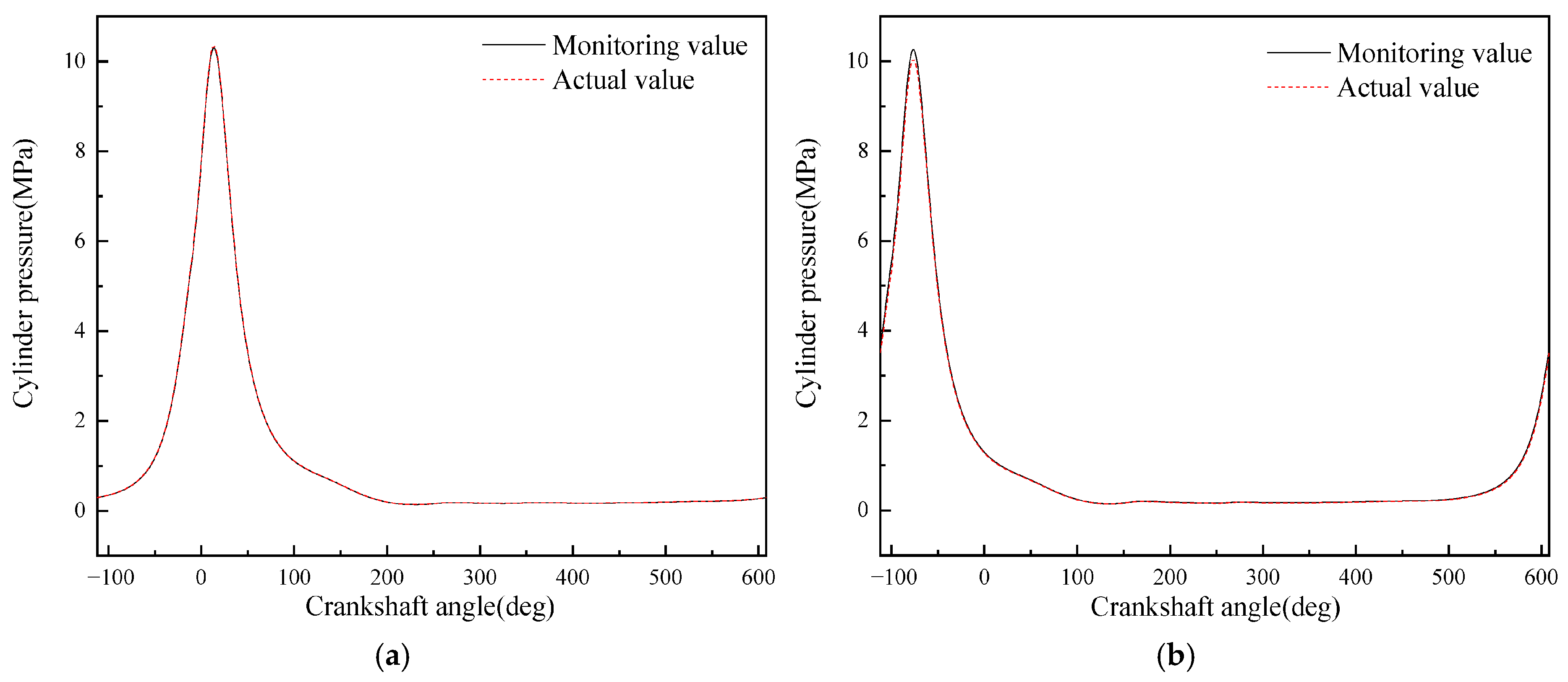
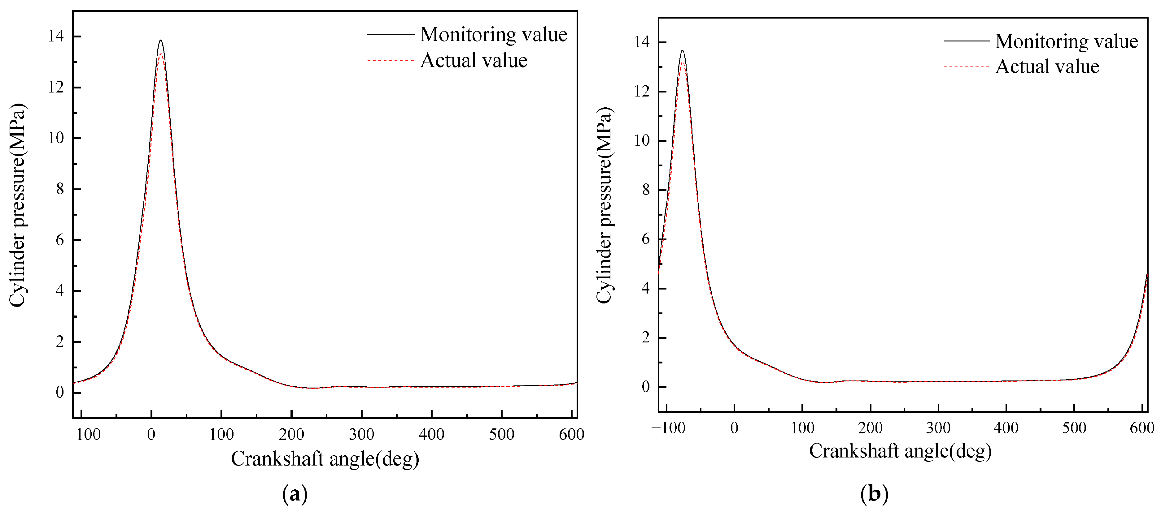
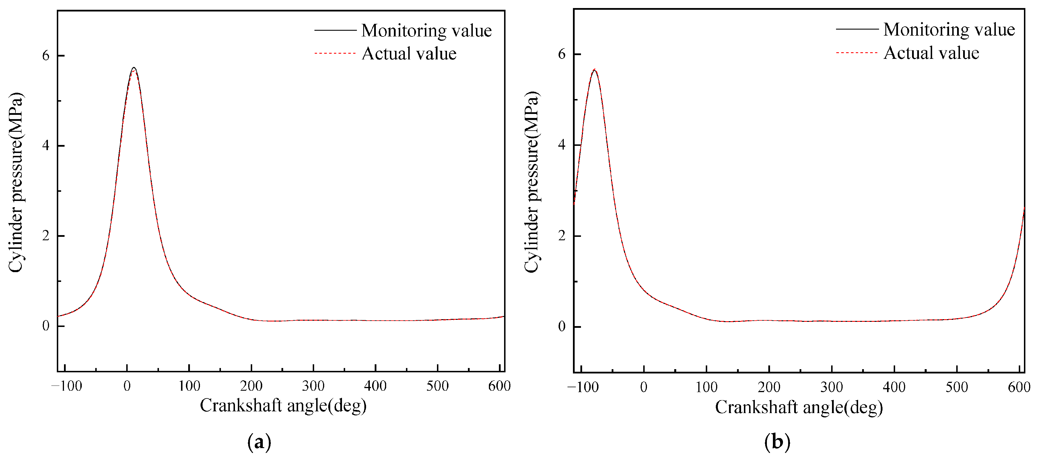
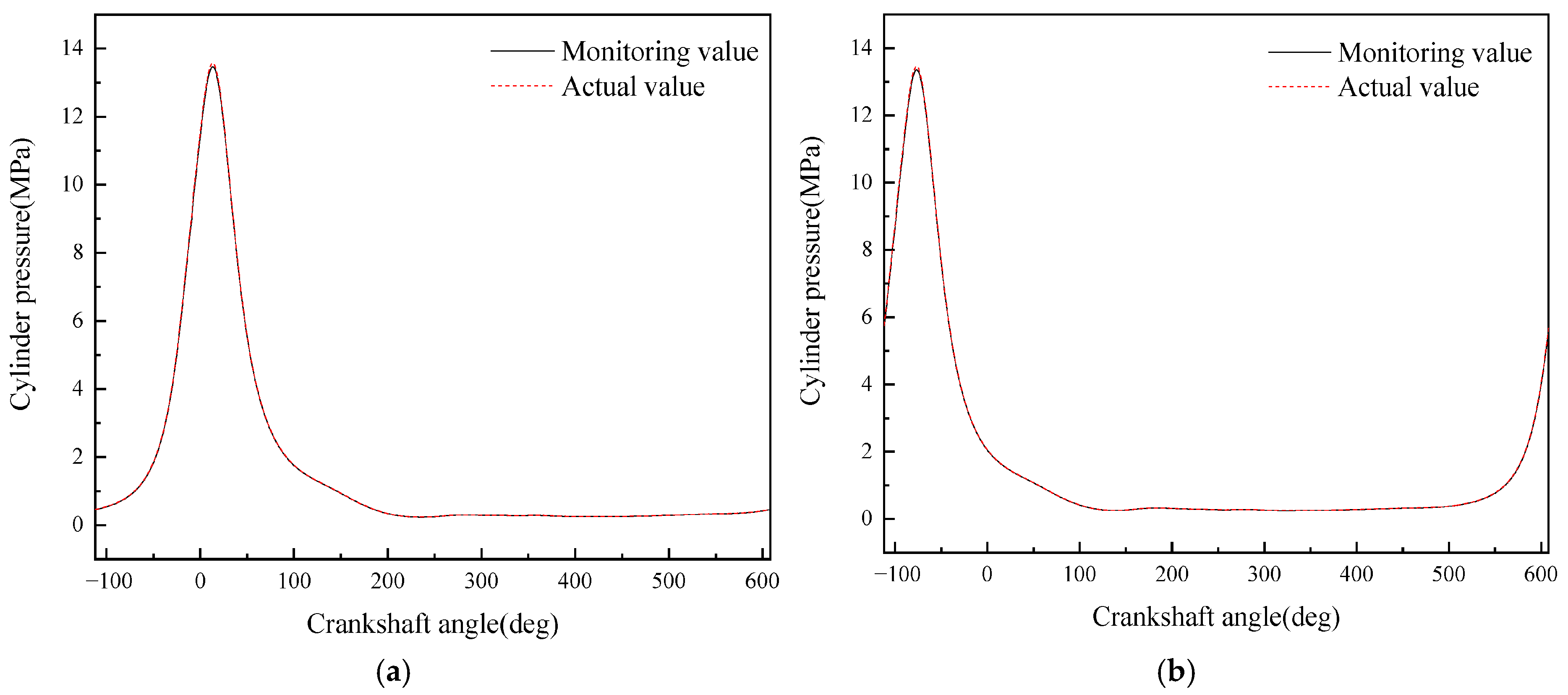
- A diesel engine in-cylinder pressure monitoring model based on GRU is established in this paper. With sufficient training data, the observation accuracy of the in-cylinder pressure curve under different operating conditions is high. After verification under nine operating conditions (three speeds: 1600 rpm, 1800 rpm, 2000 rpm; three loads: 25%, 75%, 100% for each speed), it is found that the average error in the moment when the in-cylinder pressure reaches the maximum value of the monitoring model proposed in this paper is 0 degrees, the maximum difference in the maximum in-cylinder pressure is 0.4826 MPa, and the maximum average in-cylinder pressure error in one working cycle is 8.05%. Moreover, the error is mainly concentrated in the compression process rather than the combustion process. In summary, the in-cylinder pressure monitoring model proposed in this paper has good accuracy.
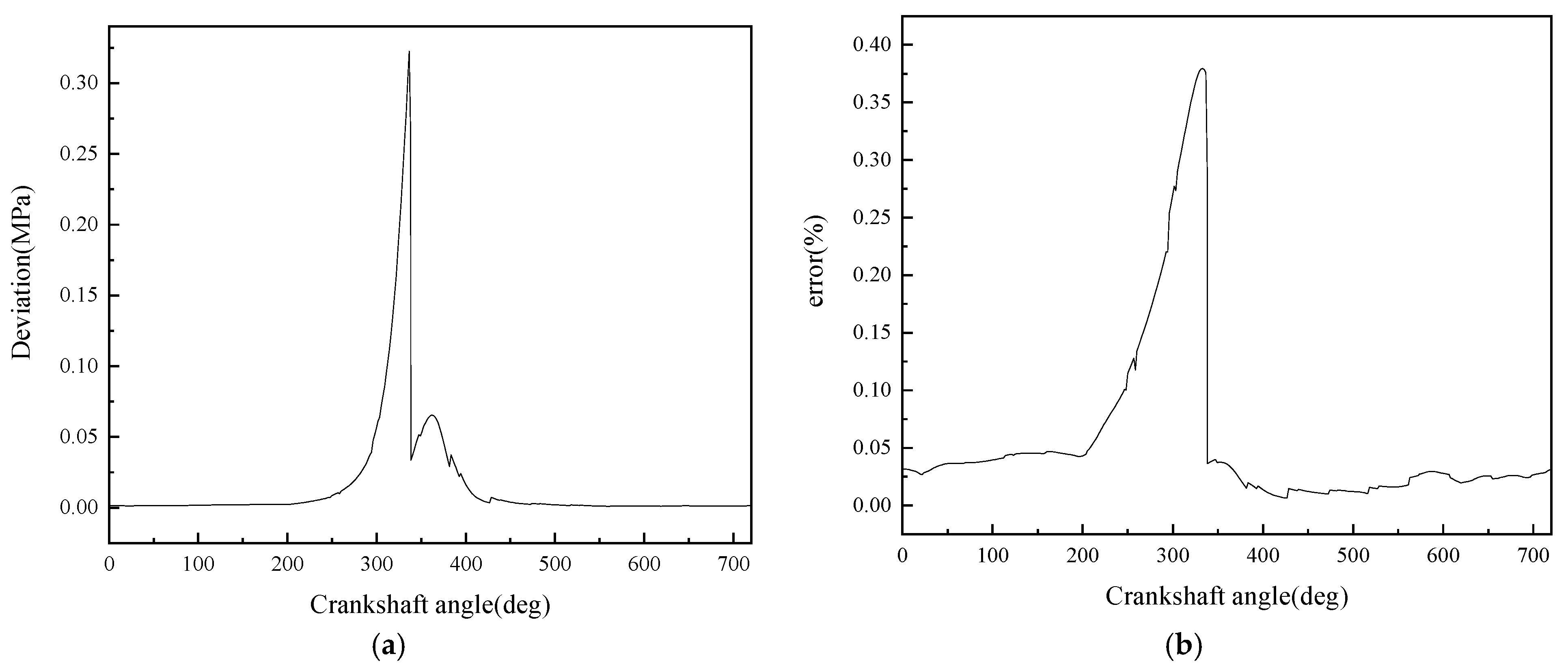
- Although the average in-cylinder pressure error of the monitoring model proposed in this paper increases with the increase in the maximum in-cylinder pressure, the error of the maximum in-cylinder pressure does not change significantly. This is because the error mainly occurs in the range of crankshaft angle from 290° to 340°, i.e., the compression stroke; while when the crankshaft angle is in the range of 360° to 450°, i.e., the power stroke, the error is small.
- It can be seen from the comparison in this paper that the combined use of artificial neural network and torque signal to monitor engine in-cylinder pressure changes has two advantages over other methods: good timeliness and high monitoring accuracy. In terms of timeliness, on the same computing platform, compared with traditional monitoring methods using simulation models, the average computation time of the monitoring model established in this paper is only 0.0109 s, while the average computation time using simulation models is 3271.11 s. This greatly improves monitoring efficiency and makes real-time monitoring of the overall operating state of the engine possible. In terms of monitoring accuracy, compared with using vibration signals as the data source, the monitoring model using torque signals has absolute advantages in average in-cylinder pressure error and maximum in-cylinder pressure error, which are reduced by 82.1% and 59.4%, respectively. Moreover, it can even achieve zero error in monitoring the difference in the occurrence time of the maximum in-cylinder pressure.
Author Contributions
Funding
Data Availability Statement
Conflicts of Interest
Appendix A
| Type | Parameter Input | Parameter Unit | Data Value |
|---|---|---|---|
| Overall Parameters | Diesel Engine Type | —— | Four-stroke diesel engine |
| Rated Speed | r/min | 2000 | |
| Cylinder Arrangement | —— | V-type 90° | |
| Cylinder Numbering Sequence | —— | Flywheel end, left (Bank A) and right (Bank B) in sequence | |
| Crankshaft Rotation Direction (viewed from power output end) | —— | Counterclockwise | |
| Cylinder Firing Order | —— | A1B5A3A5B2B8A2A8B3A7B4B6A4A6B1B7 | |
| Interval Angle | °CA | 45 | |
| Average Mechanical Loss Pressure | —— | 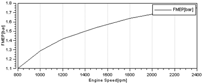 | |
| Cylinder | Combustion Chamber Type | —— | ω |
| Average Crankcase Pressure | MPa | 0.1 | |
| Combustion Heat Release Model | —— | Vibe model | |
| Combustion Duration (adjusted result) | °CA | 72 | |
| Vibe Parameter a | —— | 6.9 (complete combustion) | |
| Combustion Quality Index m (adjusted result) | —— | 0.925 | |
| Intake Valve Lift Curve | —— |  | |
| Exhaust Valve Lift Curve | —— | 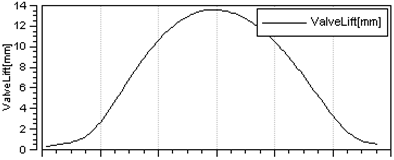 | |
| Intake Valve Flow Coefficient Curve | —— | 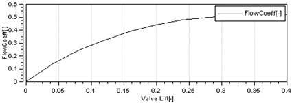 | |
| Exhaust Valve Flow Coefficient Curve | —— |  | |
| Air Filter CL1 | Total Volume | L | 100 |
| Inlet Volume | L | 52 | |
| Outlet Volume | L | 30 | |
| Mass Volume Flow Rate | m3/s | 2.91 | |
| Pressure Drop | bar | 0.02 | |
| Inlet Pressure | bar | 1 | |
| Inlet Temperature | °C | 24.85 | |
| Intercooler CO1 | Cooling Water Flow Rate | kg/s | 2.17 |
| Pressure Drop | bar | 0.035 | |
| Outlet Temperature | °C | 53 | |
| Inlet Temperature | °C | 160 | |
| Intake Manifold (Main) | Total Volume | L | 16 |
| Initial Temperature | °C | 25 | |
| Initial Pressure | bar | 1 | |
| Intake Manifold (Branch) | Pipe Length | mm | 200 |
| Pipe Diameter | mm |  | |
| Radius of Curvature | mm | 1,000,000 | |
| Friction Coefficient (empirical value) | —— | 0.038 | |
| Heat Transfer Factor (empirical value) | —— | 1 | |
| Wall Temperature (initial boundary) | °C | 25 | |
| Exhaust Manifold (Branch) | Pipe Length | mm | 220 |
| Pipe Diameter | mm | 78 | |
| Radius of Curvature | mm | 1,000,000 | |
| Friction Coefficient (empirical value) | —— | 0.038 | |
| Heat Transfer Factor (empirical value) | —— | 1.1 | |
| Wall Temperature (initial boundary) | °C | 25 | |
| Exhaust Manifold (Main) | Pipe Length | mm | 228 |
| Pipe Diameter | mm | 110 | |
| Radius of Curvature | mm | 1,000,000 | |
| Friction Coefficient (empirical value) | —— | 0.03 | |
| Heat Transfer Factor (empirical value) | —— | 1.8 | |
| Wall Temperature (initial boundary) | °C | 25 |
References
- Milojević, S.; Savić, S.; Marić, D.; Stopka, O.; Krstić, B.; Stojanović, B. Correlation between Emission and Combustion Characteristics with the Compression Ratio and Fuel Injection Timing in Tribologically Optimized Diesel Engine. Teh. Vjesn. 2022, 29, 1210–1219. [Google Scholar] [CrossRef]
- Chang, C.; Mei, J.M.; Zhao, H.M.; Shen, H.; Li, X.H. Cylinder Pressure Identification Based on Local Tangent Space Alignment and Least Squares Support Vector Machine. J. Vib. Shock. 2020, 39, 16–21+63. [Google Scholar]
- Liu, J.M.; Li, X.L.; Qiao, X.Y.; Zhang, J. Research on Cylinder Pressure Identification Method of Diesel Engine Under Multiple Operating Conditions Based on Cylinder Head Vibration Signal. Automot. Eng. 2015, 37, 875–880+979. [Google Scholar]
- Liu, J.M.; Li, H.Y.; Qiao, X.Y.; Li, X.L.; Shi, Y.P. Research on Cylinder Pressure Identification Method Based on Cylinder Head Vibration Signal. Intern. Combust. Engine Eng. 2013, 34, 32–37. [Google Scholar]
- Liu, S.X.R. Research on Diesel Engine In-Cylinder Pressure Identification Method Based on Cylinder Head Vibration Signal. Master’s Thesis, Harbin Engineering University, Harbin, China, 2013. [Google Scholar]
- Ji, S.B.; Cheng, Y.; Tang, J.; Lan, X.; Yang, B. Research on Cylinder Pressure Identification Based on Time-domain Characteristics of Cylinder Head Vibration Signal. Intern. Combust. Engine Eng. 2008, 29, 76–80. [Google Scholar]
- Chen, B. Research on Gas Pressure Reconstruction Method Based on Cyclostationary Characteristics of Diesel Engine. Master’s Thesis, Wuhan University of Technology, Wuhan, China, 2009. [Google Scholar]
- Yang, Y.F. Research on Prediction of Vibration and Noise of Diesel Engine Considering the Influence of Component Joint Surface Connection Characteristics. Master’s Thesis, Harbin Engineering University, Harbin, China, 2022. [Google Scholar]
- Yao, J.J.; Xiang, Y.; Wang, Z.H. Diesel Engine Cylinder Pressure Identification Based on Transfer Function Method. J. Wuhan Univ. Technol. (Transp. Sci. Eng. Ed.) 2006, 30, 70–72. [Google Scholar]
- Yao, J.J.; Xiang, Y.; Zhou, Y. Diesel Engine Cylinder Pressure Identification Based on Cepstrum Method. Shipp. Eng. 2006, 37–39. [Google Scholar]
- Zhang, Z.R.; Shi, L.S.; Wang, C.D. Diesel Engine Cylinder Pressure Identification Based on Wavelet Analysis and Time Series Analysis. Trans. Chin. Soc. Intern. Combust. Engines 1999, 17, 136–139. [Google Scholar]
- Chen, G.J.; Zhang, Y.D. Gas Pressure Identification Based on Wavelet Analysis and ARMA Model. J. Vib. Eng. 2002, 15, 484–487. [Google Scholar]
- Gao, H.B.; Ouyang, G.Y.; Zhang, P. Diesel Engine Cylinder Pressure Reconstruction Based on BP Neural Network. Intern. Combust. Engine Eng. 2005, 26, 68–70. [Google Scholar]
- Saimurugan, M.; Ramachandran, K.I.; Sugumaran, V.; Sakthivel, N.R. Multicomponent fault diagnosis of rotational mechanical system based on decision tree and support vector machine. Expert Syst. Appl. 2011, 38, 3819–3826. [Google Scholar] [CrossRef]
- Zhang, H.R.; Han, Z.Z.; Li, C.G. Nonlinear System Identification Based on Support Vector Machine. J. Syst. Simul. 2003, 18, 89–91. [Google Scholar]
- Shen, Z.J.; Chen, X.F.; He, Z.J. Remaining Life Prediction of Rolling Bearings Based on Relative Features and Multivariate Support Vector Machine. J. Mech. Eng. 2013, 42, 183–189. [Google Scholar] [CrossRef]
- Zhang, Z.Y.; Zha, H.Y. Principal manifolds and nonlinear dimensionality reduction via tangent space alignment. SIAM J. Sci. Comput. 2004, 26, 313–338. [Google Scholar] [CrossRef]
- Suykens, K.; Gestel, V.; Brabanter, D.; Moor, D.; Vandewalle, J. Least Squares Support Vector Machines; World Scientific Publishing Company: Singapore, 2002. [Google Scholar]
- Wang, L. Research on Several Methods of Rolling Bearing Fault Diagnosis Based on Manifold Learning. Ph.D. Thesis, Dalian University of Technology, Dalian, China, 2013. [Google Scholar]
- Ranaee, V.; Ebrahimzadeh, A.; Ghaderi, R. Application of the PSO-SVM model for recognition of control chart patterns. ISA Trans. 2010, 49, 577–586. [Google Scholar] [CrossRef] [PubMed]
- D’Ambrosio, S.; Ferrari, A. Diesel Injector Coking: Optical-Chemical Analysis of Deposits and Influence on Injected Flow-Rate, Fuel Spray and Engine Performance. J. Eng. Gas Turbines Power 2012, 134, 062801.1–062801.14. [Google Scholar] [CrossRef]
- Gao, Y.X.; Feng, Y.M.; Wang, Y.S.; Zhu, Y.Q. Effects of Partial Pre-Decomposition of Ammonia Fuel on Combustion and Greenhouse Gas Emissions in a Pre-Chamber Jet Ignition Ammonia Engine. Chin. Intern. Combust. Engine Eng. 2025, 46, 55–68. [Google Scholar] [CrossRef]
- Li, W.; Li, G.; Bai, S.; Sang, W.; Sun, J.; Liu, Y.; Zhang, X.; Han, F. The Influence of Lightweight Bearings on the Mechanical Efficiency of Turbochargers and the Acceleration Performance of Engines. Intern. Combust. Engines Power Plants 2021, 38, 35–41. [Google Scholar] [CrossRef]
- Liu, K.; Liu, X. Study on Mechanical Fatigue Damage and Reliability of Internal Combustion Engine Piston. Intern. Combust. Engine Parts 2023, 44–46. [Google Scholar] [CrossRef]
- Zhang, N. Analysis of Causes and Prevention of Internal Combustion Engine Cylinder Wear. Intern. Combust. Engine Parts 2020, 48–50. [Google Scholar] [CrossRef]
- Cong, J.; Ni, P.; Sun, J.; Lv, S. Experimental Study and Analysis on Torsional Fatigue Strength of Internal Combustion Engine Crankshaft. China Mech. Eng. 2022, 33, 2197–2204. [Google Scholar]
- Catania, A.E.; Ferrari, A.; Spessa, E. Numerical-experimental study and solutions to reduce the dwell-time threshold for fusion-free consecutive injection in a multijet solenoid-type CR system. J. Eng. Gas Turbines Power 2009, 131, 317–332. [Google Scholar] [CrossRef]
- Lino, P.; Maione, B.; Rizzo, A. Nonlinear modelling and control of a common rail injection system for diesel. Appl. Math. Model. 2007, 31, 1770–1784. [Google Scholar] [CrossRef]
- Wang, J.; Zhang, T.; Zhang, J.; Sun, H. Study on Drying Moisture Content Prediction Based on LSTM Neural Network. Liaoning Chem. Ind. 2023, 52, 1722–1726+1730. [Google Scholar] [CrossRef]
- Chen, Y.D.; Chen, S.; Chen, Y.R.; Geng, Y.D.; Shu, H. Dynamic Prediction of COVID-19 with the Extended SEIR-LSTM Model: A Case Study of Tokyo in 2022. Chin. J. Comput. Phys. 2025, 42, 631–636. [Google Scholar] [CrossRef]
- Li, L.; Su, T. Research on a small sample fault diagnosis method for a high-pressure common rail system. Adv. Mech. Eng. 2021, 13. [Google Scholar] [CrossRef]
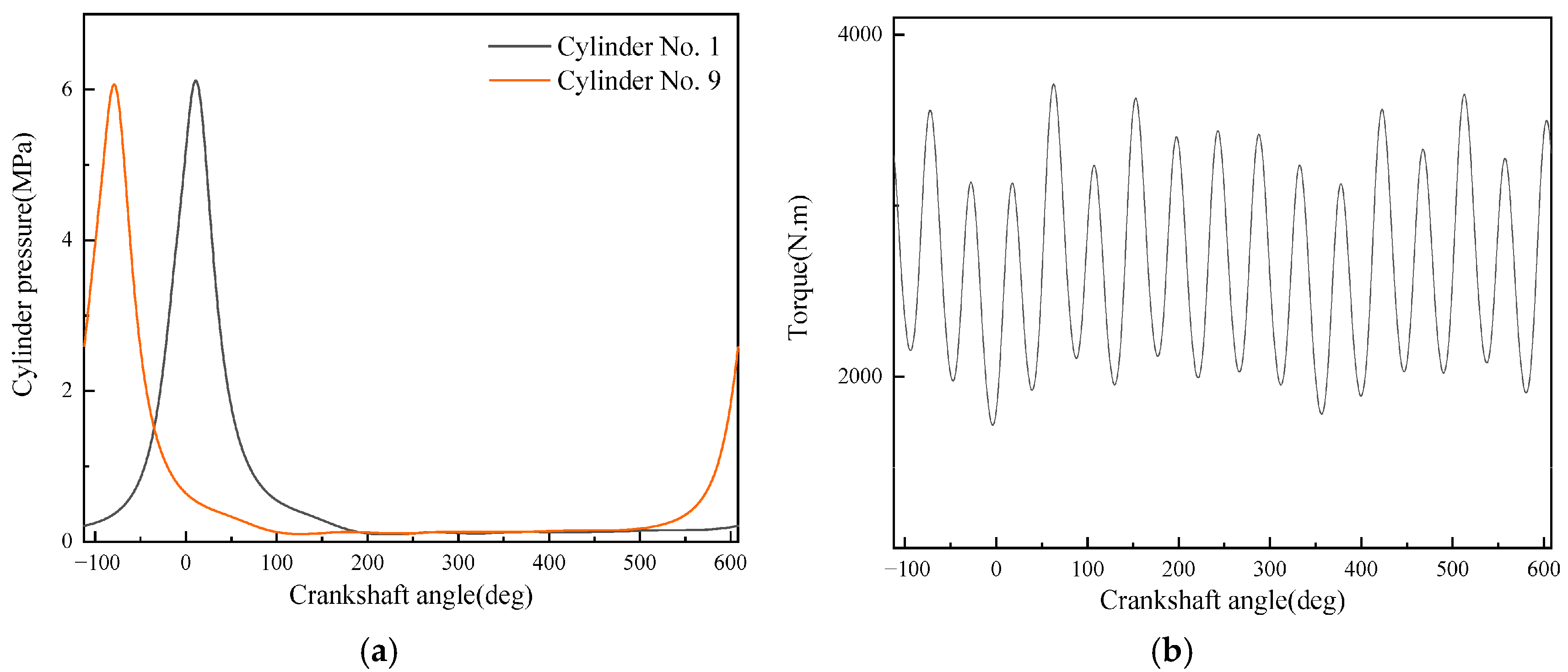
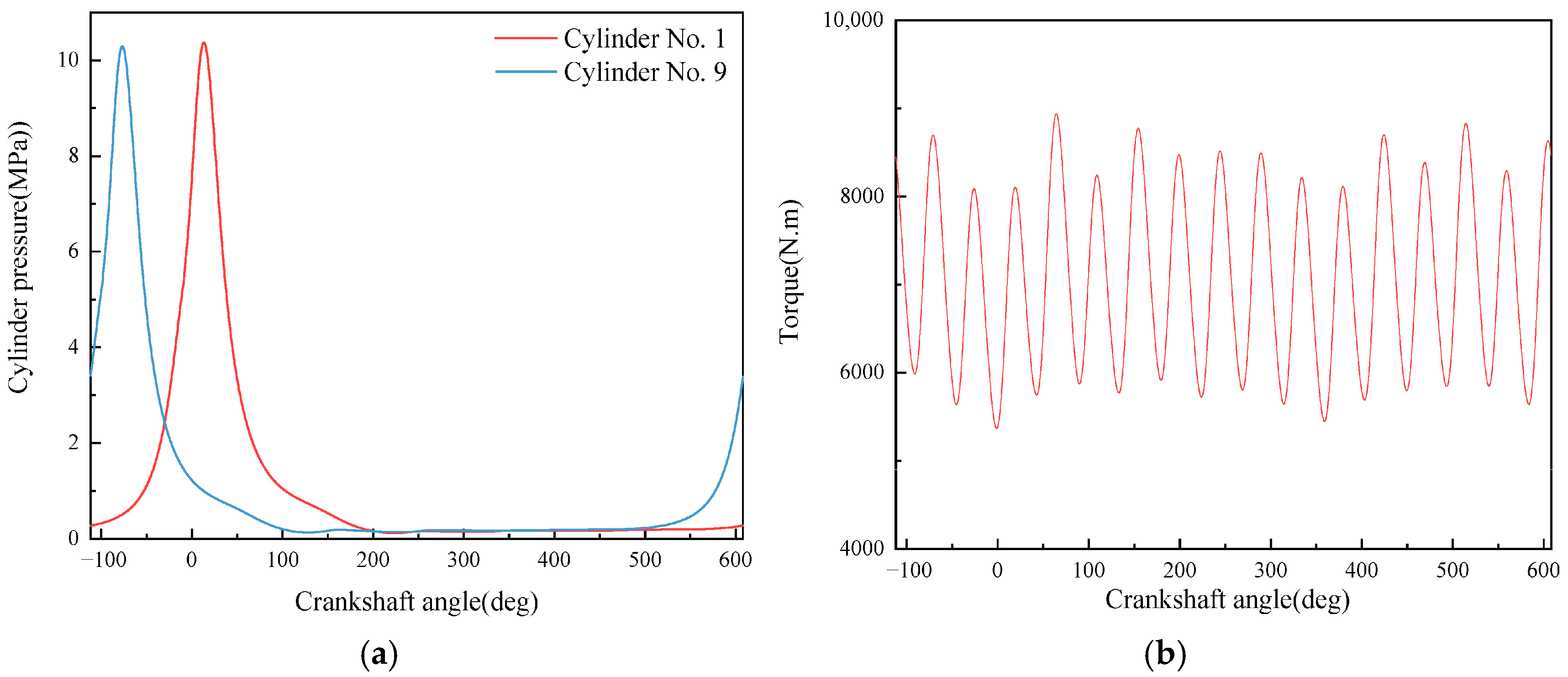
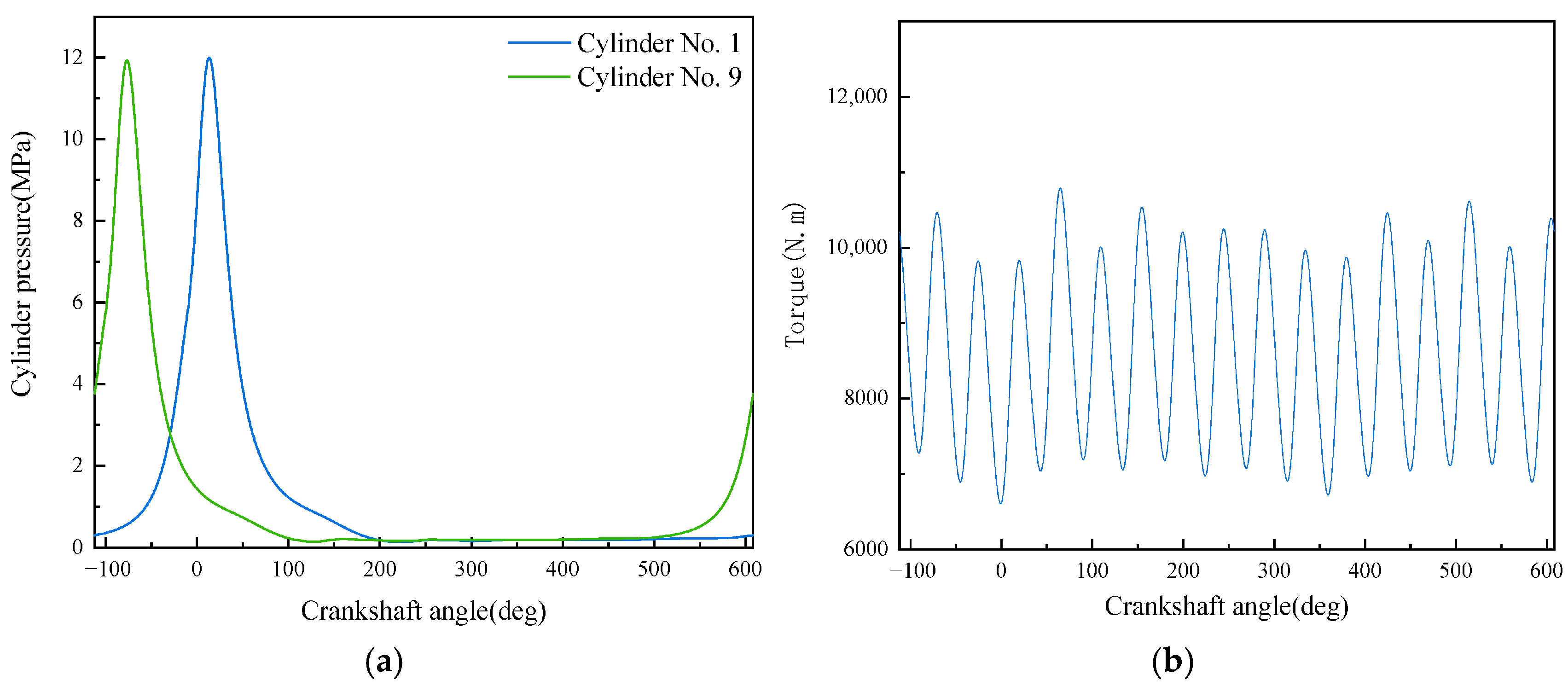
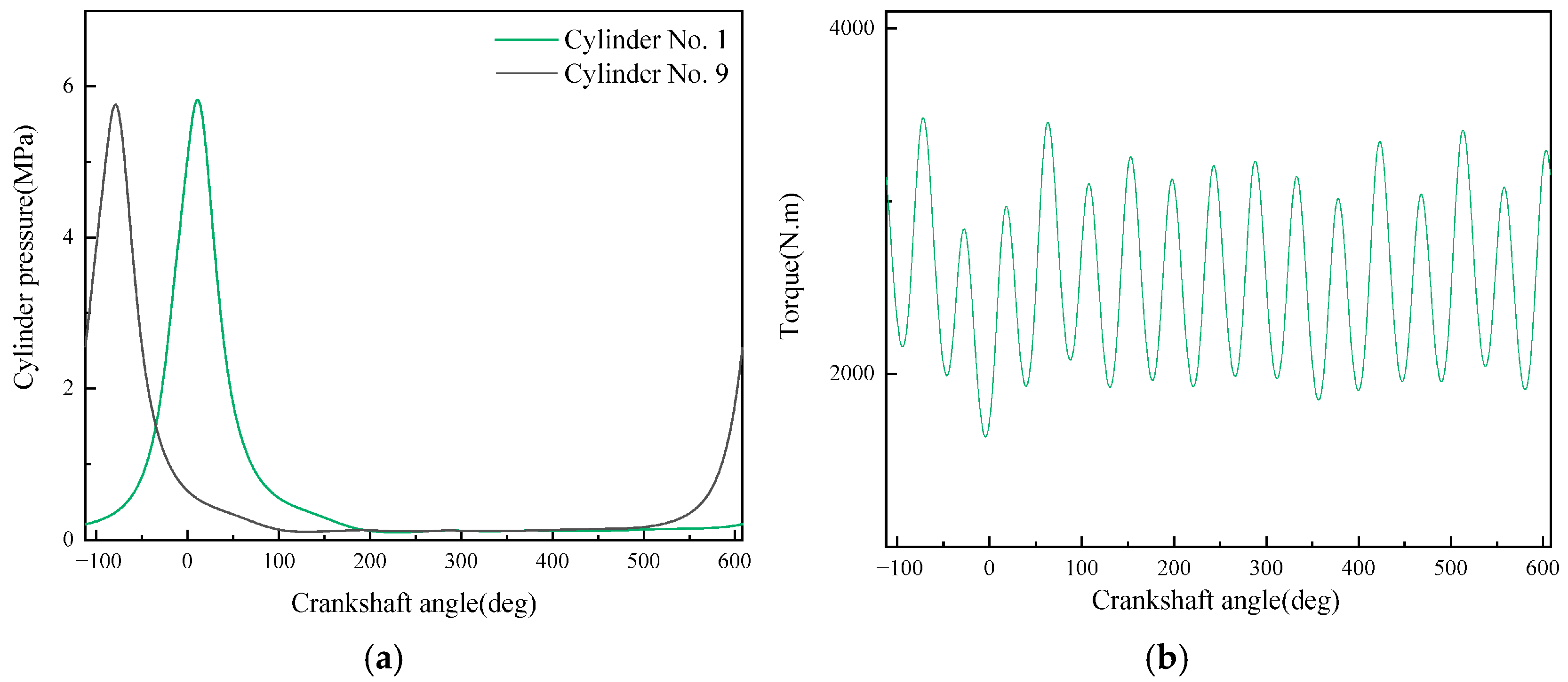
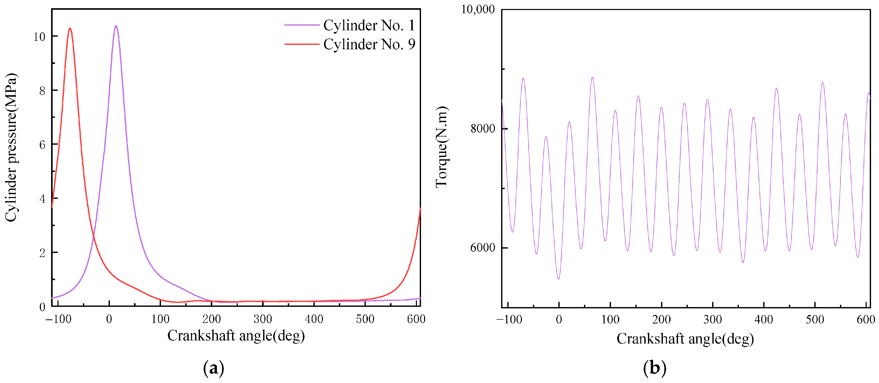

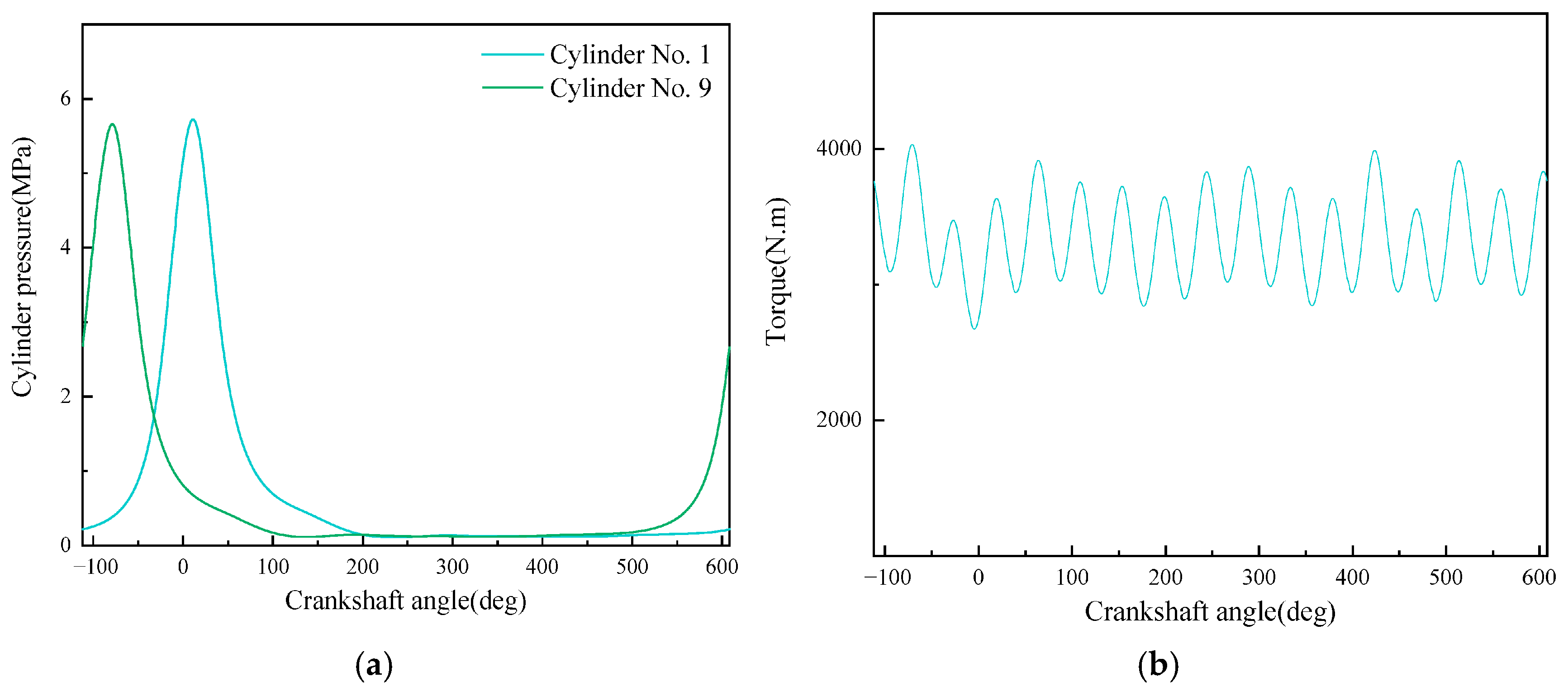
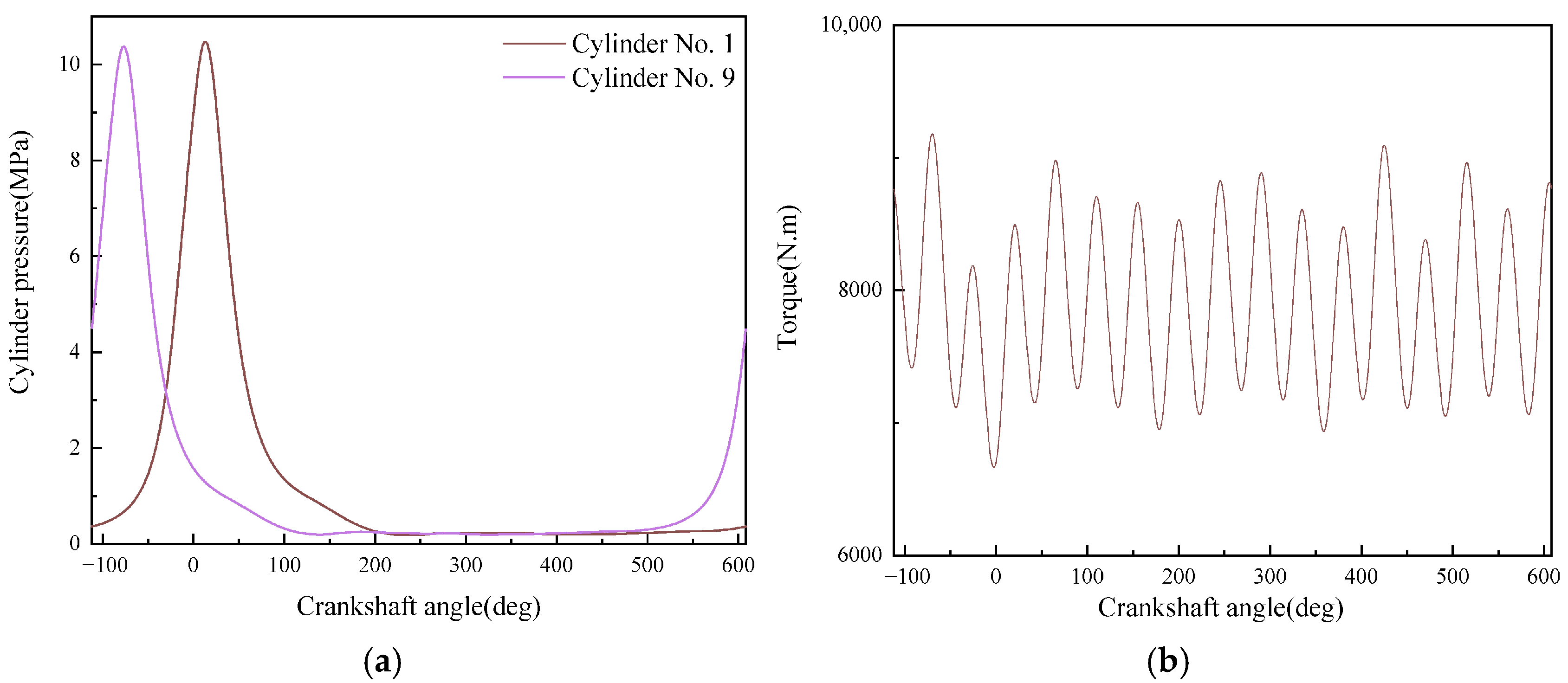
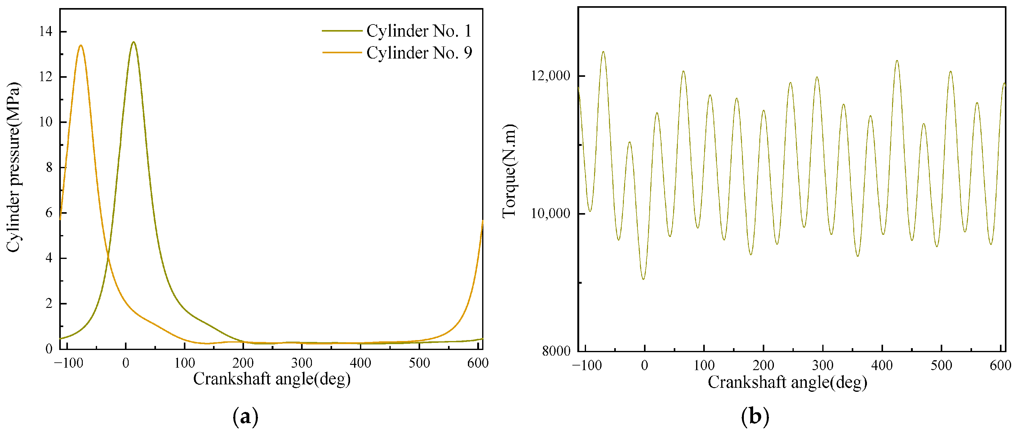


| Category | Parameter | Unit | Value |
|---|---|---|---|
| Overall Parameters | Rated engine speed | r/min | 2000 |
| Number of engine cylinders | —— | 16 | |
| Cylinder | Cylinder bore | mm | 165 |
| Connecting rod length (center distance between big end and small end) | mm | 341 | |
| Stroke | mm | 185 | |
| Compression ratio | mm | 12.3 | |
| Combustion | Fuel injection advance angle | °CA | 20 |
| Low calorific value of fuel | kJ/kg | 42,800 | |
| Fuel supply per cylinder per cycle | g/(cycle·cylinder) | 0.491 | |
| Heat Transfer | Piston heat transfer area | mm2 | 27,140 |
| Cylinder head heat transfer area | mm2 | 29,987 | |
| Cylinder liner heat transfer area | mm2 | 8022.42 | |
| Clearance height | mm | 1.42–1.79 | |
| Piston top surface temperature | °C | 430 | |
| Cylinder liner inner surface temperature | °C | 250 | |
| Cylinder head bottom surface temperature | °C | 350 | |
| Valve | Exhaust valve diameter | mm | 54 |
| Exhaust valve clearance | mm | 0.45 | |
| Exhaust advance angle | °CA | 75 | |
| Exhaust delay angle | °CA | 28 | |
| Inlet valve diameter | mm | 57 | |
| Inlet valve clearance | mm | 0.30 | |
| Inlet advance angle | °CA | 36 | |
| Inlet delay angle | °CA | 68 | |
| Number of valves | piece | 4 |
| Operating Condition No. | Speed (rpm) | Load (%) | Power (kW) | Torque (N·m) | Fuel Injection Quantity per Cycle (mg/cycle) | Air/Fuel Ratio | Supercharger Speed (rpm) | Supercharger Pressure Ratio | Temperature Before Turbine (°C) |
|---|---|---|---|---|---|---|---|---|---|
| 1 | 1600 | 25 | 444.37 | 2652.17 | 126 | 42.33 | 38,793/0 | 1.10 | 387.5 |
| 2 | 75 | 1184.86 | 7071.65 | 309 | 27.00 | 53,409/0 | 2.28 | 477.8 | |
| 3 | 100 | 1438.92 | 8587.92 | 378 | 29.15 | 41,819/41,887 | 2.63 | 552.4 | |
| 4 | 1800 | 25 | 479.34 | 2542.98 | 127 | 45.43 | 41,530 | 1.10 | 409.9 |
| 5 | 75 | 1349.59 | 7159.81 | 318 | 28.80 | 41,098/40,831 | 2.28 | 560.9 | |
| 6 | 100 | 1812.06 | 9613.30 | 419 | 27.53 | 49,019/49,018 | 2.63 | 601.7 | |
| 7 | 2000 | 25 | 699.71 | 3340.88 | 171 | 34.57 | 48,915 | 2.05 | 523.6 |
| 8 | 75 | 1653.73 | 7895.98 | 363 | 28.43 | 47,279/46,918 | 3.09 | 588.5 | |
| 9 | 100 | 2232.66 | 10,660.17 | 491 | 25.44 | 56,021/56,021 | 3.79 | 654.7 |
| Operating Condition | Data Type | Effective Power (kW) | Maximum Combustion Pressure (MPa) | Intake Air Temperature (Before Cylinder) (°C) | Exhaust Temperature (Before Turbocharger, Bank A/B) (°C) | Exhaust Temperature (After Turbocharger, Bank A/B) (°C) |
|---|---|---|---|---|---|---|
| 100% Load at 1800 r/min | Calculated Value under Experimental Conditions | 1810.8 | 13.6 | 51 | 684/684 | 596/598 |
| Experimental Value | 1812.1 | 13.6 | 56 | —— | 604/601 | |
| Calculated Value under Rated Conditions | 1828.8 | 14.1 | 60 | 668/669 | 592/594 | |
| 110% Load at 1800 r/min | Calculated Value under Experimental Conditions | 1993.4 | 14.6 | 52 | 706/706 | 622/622 |
| Experimental Value | 1993.2 | 14.5 | 56 | —— | 621/623 | |
| Calculated Value under Rated Conditions | 2025.3 | 15.1 | 62 | 690/693 | 604/602 |
| Operating Condition No. | Difference in Moment of Maximum In-Cylinder Pressure (deg) | Difference in Maximum In-Cylinder Pressure (MPa) | Average In-Cylinder Pressure Error (%) |
|---|---|---|---|
| 1 | 0.00 | 0.1504 | 3.48 |
| 2 | 0.00 | 0.3032 | 5.11 |
| 3 | 0.00 | 0.3817 | 6.47 |
| 4 | 0.00 | 0.1657 | 3.37 |
| 5 | 0.00 | 0.3267 | 5.02 |
| 6 | 0.00 | 0.4484 | 7.34 |
| 7 | 0.00 | 0.1611 | 3.39 |
| 8 | 0.00 | 0.3128 | 5.18 |
| 9 | 0.00 | 0.4826 | 8.05 |
| Method | Average In-Cylinder Pressure Error (%) | Maximum In-Cylinder Pressure Error (%) | Difference in Moment of Maximum In-Cylinder Pressure (deg) |
|---|---|---|---|
| Based on Crankshaft Torque | 5.26 | 3.02 | 0 |
| Based on Simulation Model | 5.52 | 5.11 | 0 |
| Based on Vibration Signals | 29.41 | 7.45 | 1 |
Disclaimer/Publisher’s Note: The statements, opinions and data contained in all publications are solely those of the individual author(s) and contributor(s) and not of MDPI and/or the editor(s). MDPI and/or the editor(s) disclaim responsibility for any injury to people or property resulting from any ideas, methods, instructions or products referred to in the content. |
© 2025 by the authors. Licensee MDPI, Basel, Switzerland. This article is an open access article distributed under the terms and conditions of the Creative Commons Attribution (CC BY) license (https://creativecommons.org/licenses/by/4.0/).
Share and Cite
Zhang, Y.; Li, L.; Liu, Y.; Yao, S.; Zou, R. Research on In-Cylinder Pressure Monitoring Method of Diesel Engine Based on LSTM. Appl. Sci. 2025, 15, 11979. https://doi.org/10.3390/app152211979
Zhang Y, Li L, Liu Y, Yao S, Zou R. Research on In-Cylinder Pressure Monitoring Method of Diesel Engine Based on LSTM. Applied Sciences. 2025; 15(22):11979. https://doi.org/10.3390/app152211979
Chicago/Turabian StyleZhang, Yi, Liangyu Li, Yanzhe Liu, Shiliang Yao, and Run Zou. 2025. "Research on In-Cylinder Pressure Monitoring Method of Diesel Engine Based on LSTM" Applied Sciences 15, no. 22: 11979. https://doi.org/10.3390/app152211979
APA StyleZhang, Y., Li, L., Liu, Y., Yao, S., & Zou, R. (2025). Research on In-Cylinder Pressure Monitoring Method of Diesel Engine Based on LSTM. Applied Sciences, 15(22), 11979. https://doi.org/10.3390/app152211979


