Article

Three-Phase Powerline Energy Harvesting Circuit with Maximum Power Point Tracking and Cold Start-Up

1
Electrical and Computer Engineering Department, University of North Carolina at Charlotte, Charlotte, NC 28223, USA
2
Advanced Railroad Vehicle Division, Korea Railroad Research Institute (KRRI), Building #5, Cheoldobangmulgwan-ro 176, Uiwang-si 16105, Republic of Korea
3
Corechips Co., Ltd., Human Sky Vally #415, Omokcheon-ro 132, Beon-gil 33, Gwonseon-gu, Suwon-si 16642, Republic of Korea
4
The Bradley Department of Electrical and Computer Engineering, Virginia Tech, Blacksburg, VA 24061, USA
*
Author to whom correspondence should be addressed.
Appl. Sci. 2025, 15(22), 11954; https://doi.org/10.3390/app152211954
Submission received: 5 October 2025 / Revised: 30 October 2025 / Accepted: 4 November 2025 / Published: 11 November 2025
(This article belongs to the Section Electrical, Electronics and Communications Engineering)

Abstract

This paper presents a three-phase powerline energy harvesting circuit with doubly regulated output voltages to power wireless sensors for the monitoring of railroad powerline status. Three ring-shaped silicon steel cores coupled to the three phases of a powerline convert the line current into three-phase voltages, which are applied to an energy harvesting circuit. The key parts of the circuit are a series three-phase voltage rectifier, a buck–boost converter operating in discontinuous conduction mode (DCM), and a microcontroller unit (MCU) for maximum power point tracking (MPPT). The MCU performs two-step MPPT, coarse and fine, for impedance matching based on the perturb and observe method. Two parallel voltage regulators deliver 5 V and 5.7 V regulated DC voltages to power a radio and a set of sensors, respectively. The energy harvesting circuit is prototyped using commercial-off-the-shelf (COTS) components on an FR4 PCB. The measured maximum efficiency is 84% for the three-phase voltage rectifier and 89% for the buck–boost converter under the powerline current ranging from 5 A to 20 A.

1. Introduction

In an era marked by an insatiable demand for energy and a growing imperative for sustainable practices, energy harvesting has emerged as a transformative solution. Exploiting energy harvesters for self-powered wireless sensor nodes/networks (WSNs) extends the lifetime while significantly decreasing the maintenance cost of such networks by eliminating the need for battery replacement or recharging [1,2,3,4].
WSNs for powerlines sense the voltage, current, temperature, and insulation of powerline cables [5]. Traditionally, such a WSN is powered by a wireline connection to a power source or powerline, possibly with a power transformer. However, such an approach could be expensive or possibly impractical [6]. For example, underground powerlines for railroad trains carry high voltages, and the addition of a transformer for a WSN could be costly or impractical. To address the problem, energy harvesting from powerlines is investigated [7,8,9,10,11,12,13,14,15,16,17]. Figure 1a shows a magnetic core attached around a powerline with AC current, and the secondary coil generates the AC voltage. The AC voltage can be processed to power WSNs. The magnetic core behaves as a current transformer, and Figure 1b shows a simplified equivalent circuit model of the magnetic core [18]. I p is the primary current; I s ( = I p · N p / N s ) is the secondary current. L M is a non-linear magnetizing inductance, and R s is the current transformer internal resistance.
The major goal of powerline energy harvesting is to increase the power conversion efficiency (PCE). Therefore, several works have been proposed to improve PCE and overall harvested power by the energy harvester. For example, Xu et al. added anti-saturation capability to the magnetic core to increase its efficiency by adopting an auxiliary winding to the magnetic core and regulating the magnetomotive force [14]. In another work, Li et al. increased the quality factor of the matching network between the core and the energy harvester to increase the charging power and overall efficiency of the energy harvester using an independent upconversion resonant matching loop [10]. Another popular approach to improve the PCE is optimizing the physical parameters of the core and the energy harvester to maximize the PCE under a specific operation condition ( I , V ) [15]. Related works mostly focused on improving the performance of the magnetic core; however, sub-optimum operation due to variation in the characteristics of the line can dominate the overall efficiency of the energy harvesting system. Furthermore, the power source of the introduced works is limited to a single-phase powerline, and utilizing them for three-phase powerlines requires exhaustive modification and/or optimization of the circuit.
In this paper, we present energy harvesting from three-phase powerlines for railroad trains. The introduced energy harvesting circuit processes voltages from three magnetic cores attached around three powerlines [19]. A buck–boost converter operating in discontinuous conduction mode (DCM) performs impedance matching between the powerline and input of the rectifiers [20,21]. Due to powerline current variations, the impedance of the powerline is prone to change. Hence, a maximum power point tracking (MPPT) algorithm based on perturb and observe (P&O) dynamically adjusts the input impedance of the circuit at its optimum [22]. Our earlier works on powerline energy harvesting are presented in [7], and this paper extends earlier work to three-phase powerlines.
This paper is organized as follows. Section 2 discusses the design and optimization procedure of different building blocks in the energy harvester circuit and its expansion to three-phase input signals. The experimental results are discussed and interpreted in Section 3. Finally, Section 4 concludes this work.

2. Introduced Energy Harvester

In this section, we discuss the design steps of a single-phase powerline energy harvesting circuit in detail. This will be used to design a three-phase energy harvester by making minimum necessary modifications in its architecture and operating algorithm.

2.1. Single-Phase Energy Harvester

Figure 2 shows the simplified schematic of the preliminary design of the energy harvester. The powerline is surrounded by a silicon steel core to form a current transformer (CT). In order to carry out the calculations and perform simulations, a simplified model of the CT is used, as shown in Figure 2. L m is the magnetizing inductance and R s represents the loss of the secondary winding as a series resistance. The induced current in the secondary winding is then fed into the diode bridge rectifier to provide a DC voltage across C r e c t . Finally, the voltage regulator adjusts (e.g., steps-down/steps-up) to a desired level at the output port V L . Although the energy harvester may be able to produce DC voltage across the load resistance, it does not guarantee optimal power delivery to the load due to any mismatch between source impedance Z S and the input impedance Z i n [23].

2.1.1. Source Impedance Matching

In order to maximize the transferred power from an AC source with a known impedance Z S , the load impedance must be equal to the complex conjugate of the source impedance, i.e., Z s = Z i n * in Figure 2. However, complex conjugate matching may not be feasible in most practical cases due to the large reactive part of the source impedance, i.e., { Z s } . Therefore, we limit the matching condition to resistive matching only, i.e., R s = R i n [21]. Although this makes the realization of impedance matching more practical, the efficiency of power transfer is smaller compared to the case under complex conjugate matching [24].
The power delivered to the voltage rectifier can be given by
P i n = R s 2 + X s 2 R i n + ( R s 2 + X s 2 ) R i n + 2 R s I s 2 .
From (1), the optimum input resistance can be calculated as
R i n , o p t = R s 2 + X s 2 .
In order to provide the optimum impedance R i n , o p t at the input of the energy harvester, a buck–boost converter operating in discontinuous conduction mode (DCM) is adopted after the voltage rectifier, as shown in Figure 2. The effective input resistance of the buck–boost converter ( R B B ) can be estimated using the following expression:
R B B = 2 L D c 2 T s
where L is the inductance of the buck–boost converter, and D c and T s are the duty cycle and the switching frequency of the main switch M 1 , respectively. Interestingly, R B B is independent of the input resistance of the next stage ( R V R ), e.g., voltage regulator. Therefore, it can be controlled through the variable parameters on the right-hand side of (3), and hence, the input impedance of the rectifier. The full derivation of Equations (1)–(3), including the equivalent circuit and detailed power expressions from the current–transformer source to the rectifier and to the buck–boost converter, was presented in our previous work [21]. Later, in this work, we will use this feature to adaptively tune the impedance with the aim of maximizing the transferred power to the load.
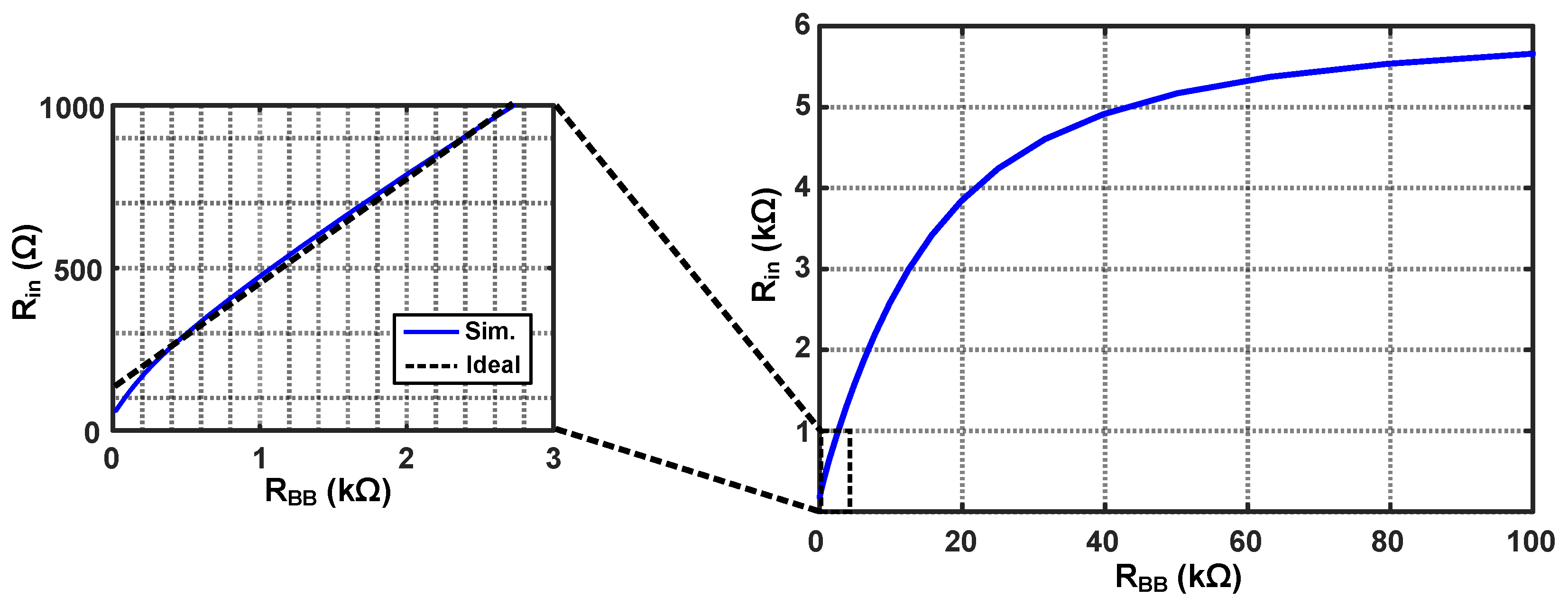
Figure 3 shows R i n versus R B B . It can be seen that the resistances have a linear relationship at a relatively small R B B ; however, the input resistance no longer keeps its linear relationship with R B B when the output impedance of the rectifier block dominates due to the impedance of the charging capacitor C r e c t . Having said this, to reduce the ripple at the output of the rectifier, C r e c t should be increased, and it will be traded off with the maximum achievable R i n . When C r e c t is small, the rectifier node voltage varies with the converter’s pulsed input current, resulting in a nearly linear relationship between the effective input resistance R i n and the theoretical buck–boost resistance R B B . In this case, the converter’s input behavior is directly related to the source. Conversely, as C r e c t increases, the rectifier voltage becomes more stable, but the dynamic coupling between the converter and the source weakens. The large capacitor effectively buffers the current, causing R i n to deviate from R B B and to saturate at higher values of R B B . This trend indicates that while a large C r e c t reduces voltage ripple, it limits the tunable range of R i n , highlighting a trade-off between ripple suppression and impedance controllability.
The relation (3) is load-independent only in strict DCM and with a slowly varying input node. Near the DCM/continuous conduction mode (CCM) boundary, or when C r e c t is small so that v i n exhibits substantial ripple at f s , the apparent input resistance becomes a function of both duty cycle and downstream operating point. This explains the non-linear region observed in Figure 3 at larger R B B where the rectifier output impedance and C r e c t dominate the port behavior.

2.1.2. Maximum Power Point Tracking (MPPT)

As it was discussed earlier in the previous section, resistive impedance matching can be performed by adjusting impedance R B B through (3). However, if the source resistance changes for any reason, such as a different primary current ( I p ), the energy harvester transfers the power under sub-optimum operating conditions, which results in a reduction in the power efficiency of the harvester. Therefore, it is crucial to calibrate R i n to realize the resistive matching condition.
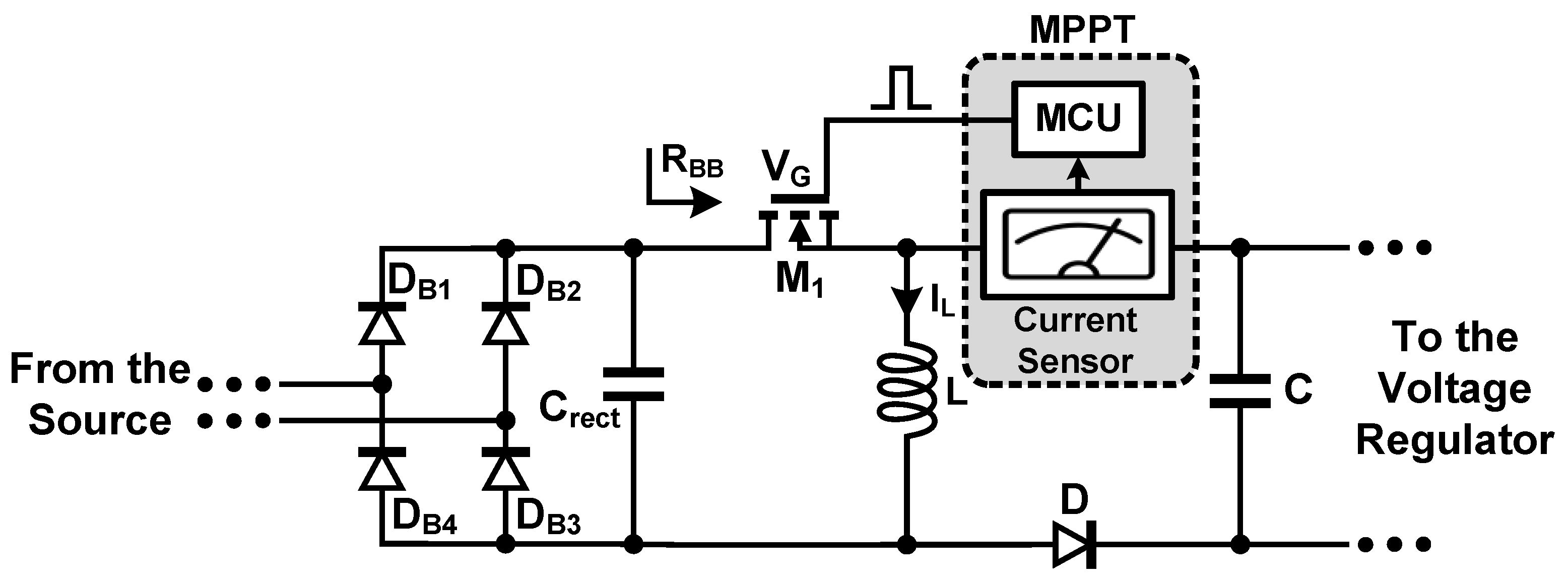
A practical and efficient approach to providing adaptive resistive matching is Maximum Power Point Tracking (MPPT) [25]. Figure 4 shows the block diagram of the MPPT along with the energy harvester.
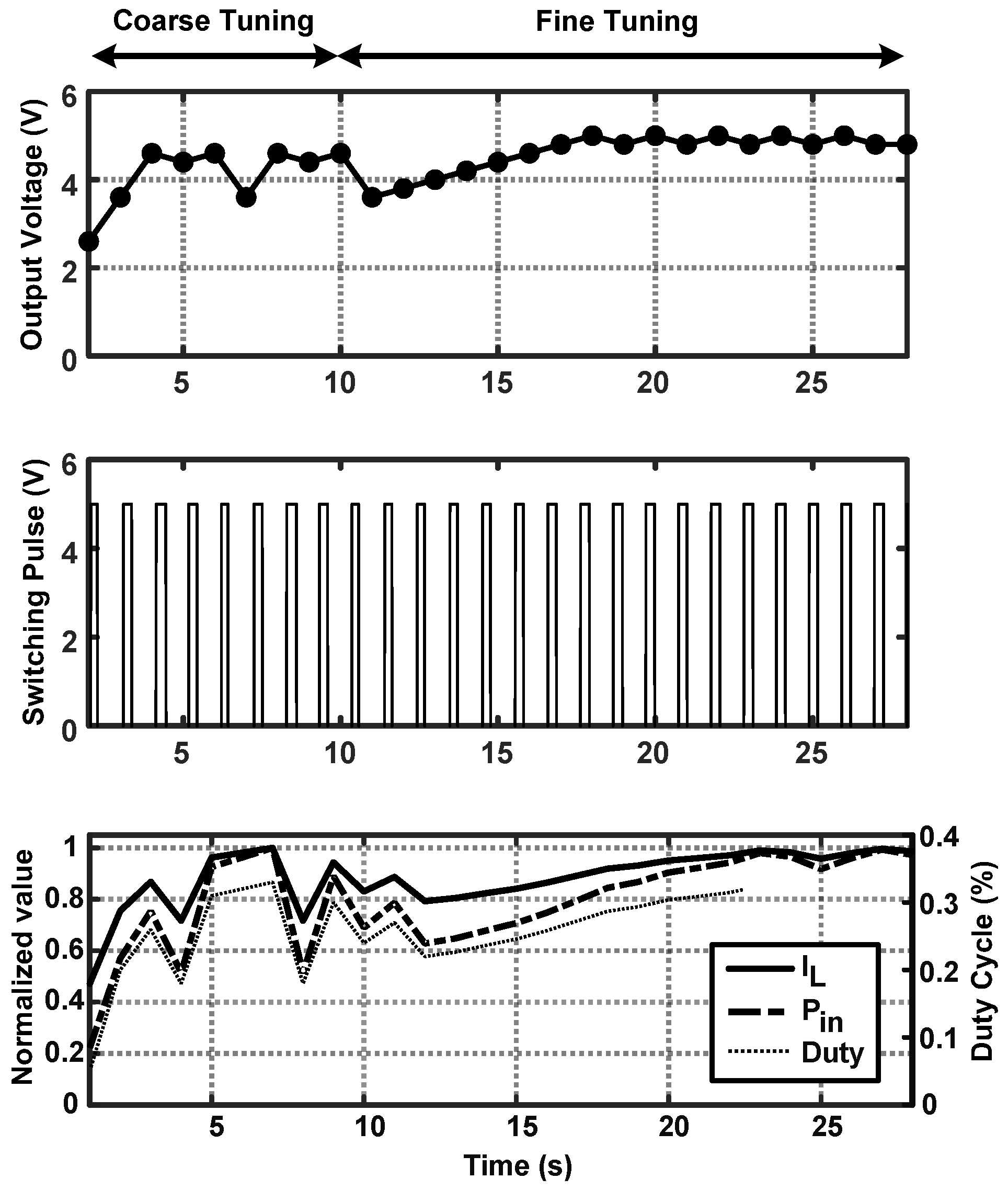
In DCM, the peak inductor current I L and the input power P i n are both strongly dependent on the duty cycle, D. From the inductor current dynamics, I L = ( V i n D T s ) / L , and the corresponding input power can be expressed as P i n = V i n 2 D 2 T s / ( 2 L ) . Therefore, P i n D 2 and I L D , implying that P i n I L 2 . This monotonic relationship means that maximizing I L directly corresponds to maximizing P i n under a fixed V i n .
Based on this property, the proposed MPPT algorithm uses the measured inductor current as an observable factor to locate the maximum power point without requiring additional voltage-sensing circuitry. During each perturbation step, the microcontroller adjusts the duty cycle and compares the updated I L magnitude with the previous sample, as shown in Figure 5, along with the inductor’s current and input power to the converter. If I L increases, the algorithm continues in the same direction; otherwise, it reverses the perturbation. This approach allows low-power and low-complexity real-time tracking of the optimum operating point.
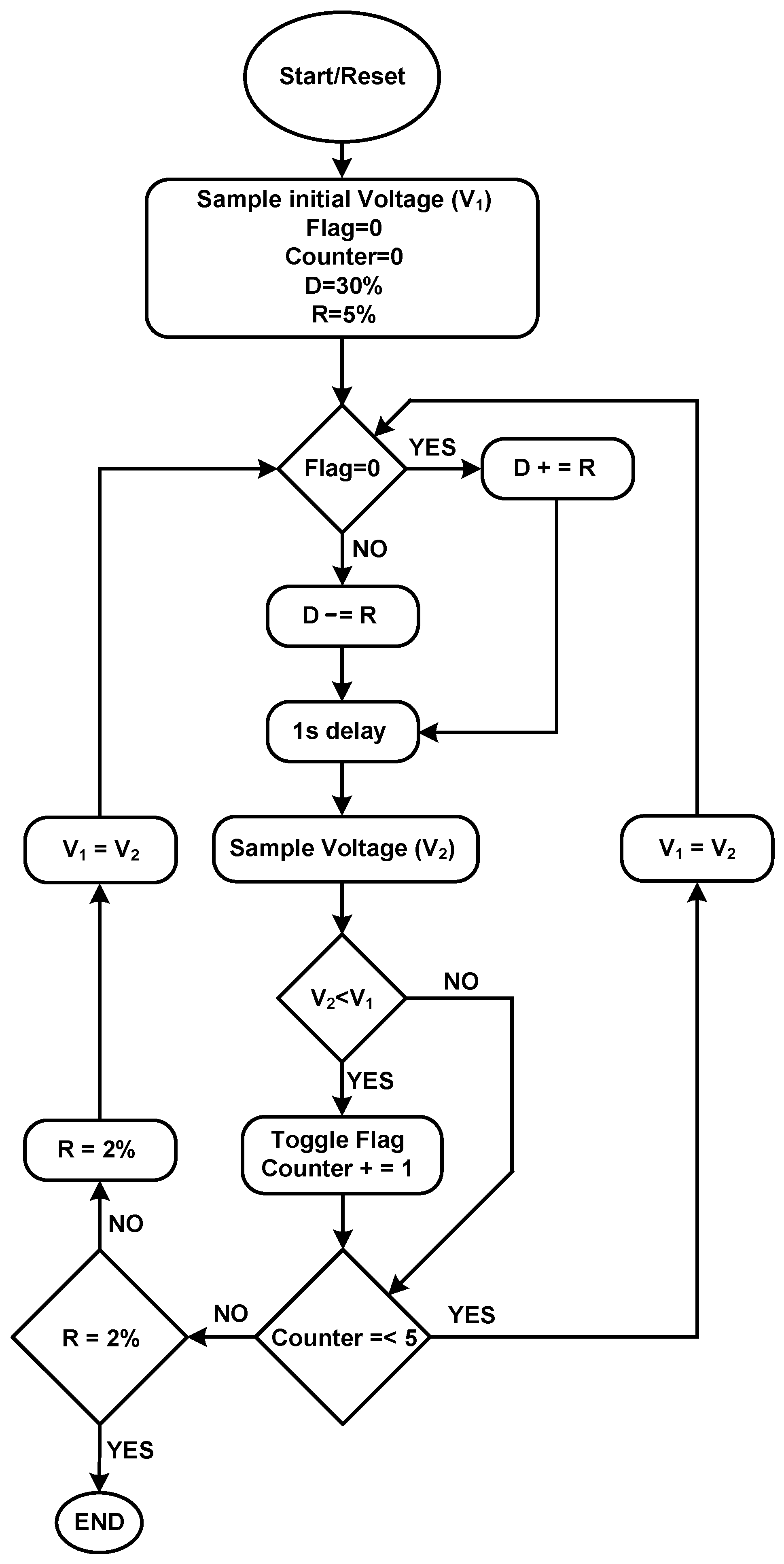
Figure 6 shows the flowchart of the designed MPPT algorithm. Initially, the MPPT feedback receives a voltage sample from the current sensor while the duty cycle of the switching pulses is set to 30% with 5% steps (coarse tuning). The MCU then adds a step to the duty cycle and waits for 1 s until it receives the next sample from the current sensor. Then, the MCU compares the previous sample with the current one and adjusts the duty cycle accordingly. The MCU repeats this procedure 5 times and then reduces the duty cycle steps to 2% (fine tuning) and repeats the entire procedure to achieve a higher accuracy.
The MPPT routine incorporates a fixed delay ( τ ) between successive duty cycle perturbations. This waiting time governs a trade-off between convergence speed and steady-state error. If τ is too short, the converter and measurement circuits do not reach steady state before the next perturbation, leading to inaccurate power evaluation and oscillatory tracking behavior. Conversely, an excessively long τ slows down convergence and reduces the responsiveness of the system to variations in the line current amplitude. The optimal value of τ depends on several factors, including the converter time constant defined by the output capacitor and inductor, the line frequency and its associated ripple period at the rectifier output, the bandwidth of the voltage and current sensing filters, and the sampling and processing delay of the MCU and ADC. In the proposed design, simulation and experimental analysis showed that τ values smaller than approximately 0.7 s cause instability due to incomplete settling, whereas τ values greater than 1 s provide stable and accurate convergence. Therefore, a 1-s waiting time was selected as an optimal compromise, ensuring reliable steady-state tracking while maintaining fast convergence under typical operating conditions.
The MPPT algorithm is implemented as a one-time calibration process executed at system startup. During this phase, the MCU perturbs the duty cycle across a predefined range and identifies the value corresponding to the maximum inductor current, which represents the maximum power point in DCM operation. After completing this sequence, the MCU fixes the duty cycle at the identified value and enters steady-state operation. Subsequent tracking is not performed automatically and if operating conditions change, the calibration can be manually reinitiated through an MCU reset. This design minimizes active control power consumption while maintaining efficient energy harvesting under stable conditions.

2.1.3. Current Sensor

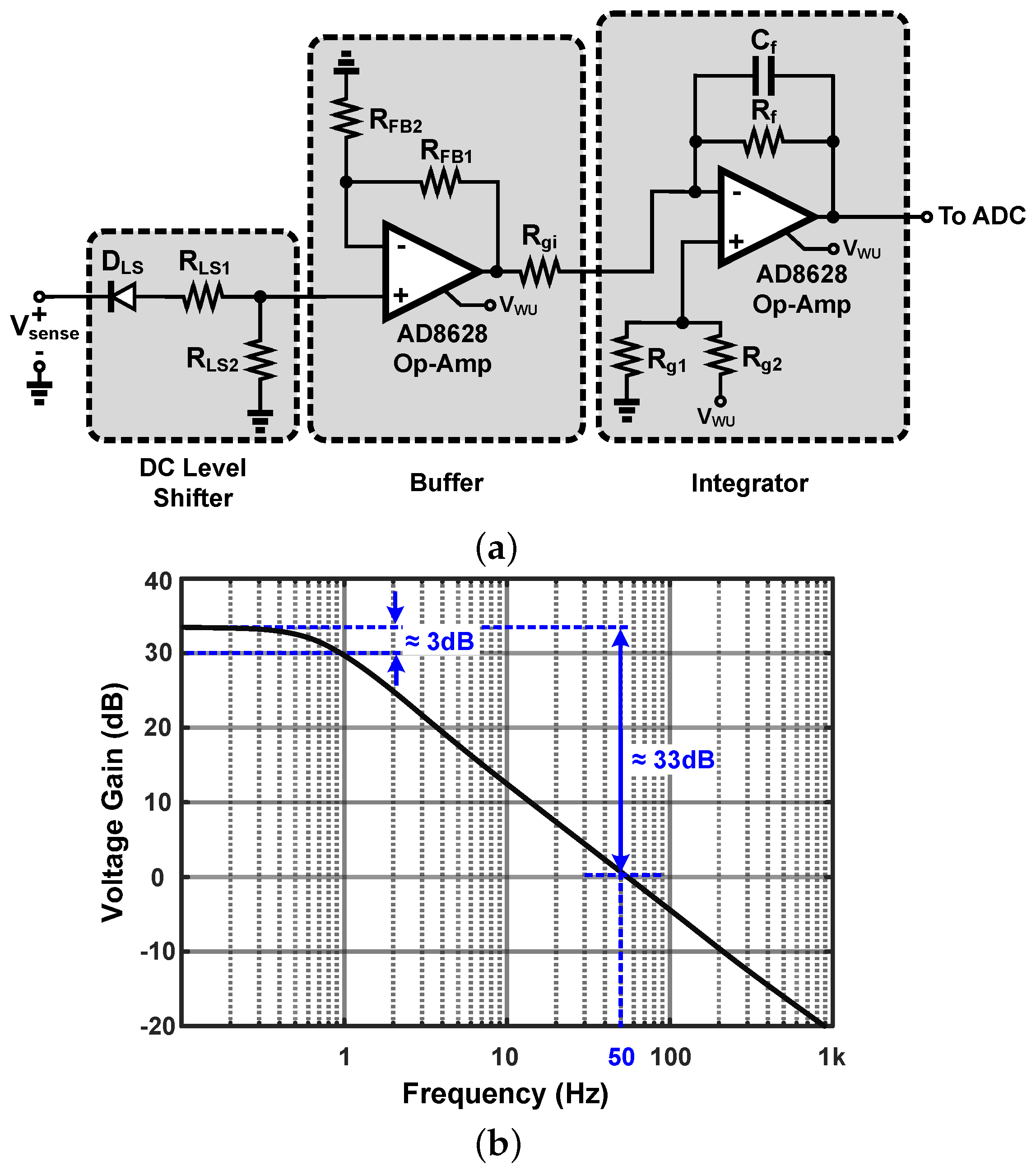
As discussed in the previous section, the MPPT block is required to sense the inductor’s current and provide the ADC with a corresponding DC voltage. This can be achieved by adding a resistor in series with the inductor’s current and then reading the voltage across the resistor, which is proportional to the current flowing through it. To prevent excessive voltage drop across this resistor, a small resistance is chosen (50 mΩ) so that its power dissipation can be neglected compared to the DC power at the output of the buck–boost converter. A DC level shifter, shown in Figure 7a, is implemented as the first stage of the current sensor to move the waveform into a positive voltage range. This allows the operational amplifiers (OAs) to operate with a single voltage supply provided by the wake-up circuit. The next stage amplifies the sensed voltage and isolates the buck–boost converter from the loading impact of the next stages of the current sensor. The last stage is an integrator to take the average of the V s e n s e and provide the ADC with a DC voltage corresponding to V s e n s e . Note that the bandwidth of the integrator is designed to be sufficiently smaller than the input frequency and switching frequency of the buck–boost converter, i.e., f 3 d B < m i n { 50 , 10 k } , to attenuate the ripples at the output.
The frequency response of the current sensor is shown in Figure 7b. It should be noted that the rate of change in V s e n s e is slow and the narrow bandwidth does not limit the tracking speed of the sensor.

2.1.4. Cold Start-Up

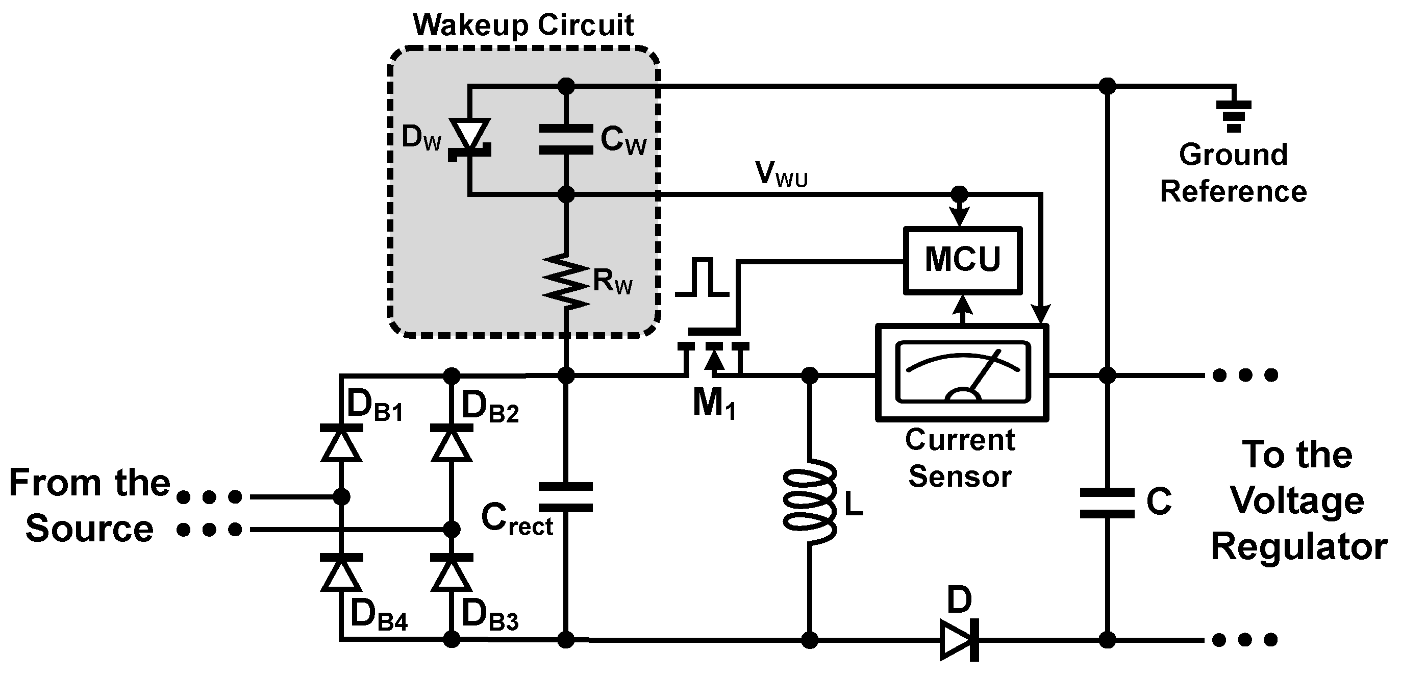
To enable the energy harvester to start up and reach its steady state without any external source of energy, e.g., battery, the circuit must be able to provide enough energy for the control loop, i.e., MCU and current sensor, to operate when the storage capacitor C is fully depleted [26].
Figure 8 shows the implementation of the wake-up circuit to build up a supply voltage for the control circuit from the rectified voltage at the output of the rectifier C r e c t . The resistor R W controls the amount of drawn current using the wake-up circuit. This value of the resistor along with the capacitor C W must be determined to find a compromise between the charging time of the capacitor and the energy storage capacity of the wake-up circuit. The Zener diode D W limits the maximum supply voltage of the control circuit to 5.1 V and prevents any damage to the circuitry. Note that the voltage reference of the wake-up circuit is the source of the switching transistor so that the single-ended control pulse, created by the MCU, will be referenced to the source of M 1 , i.e., V G S .

2.2. Extension from Single-Phase Input to Three-Phase Input

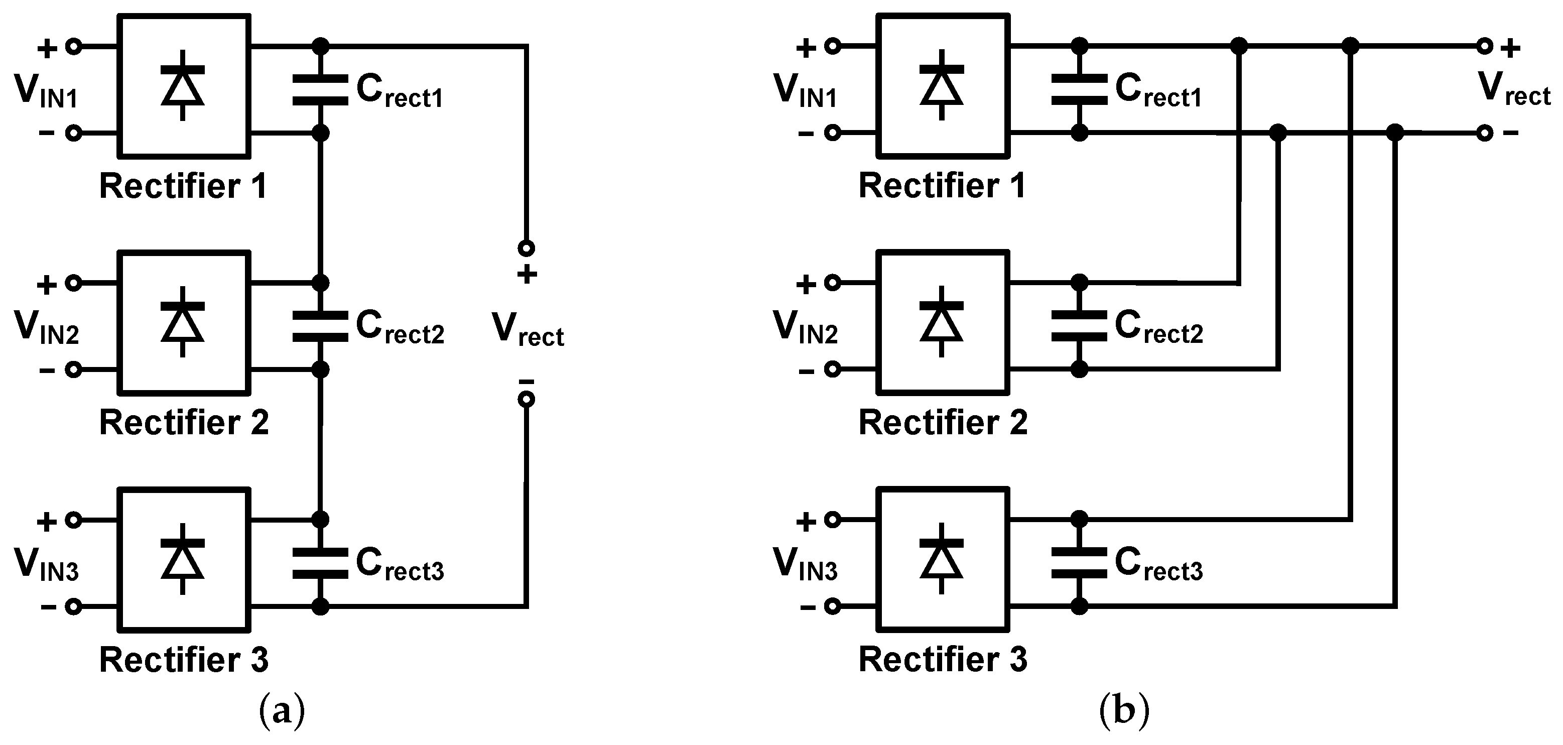
The three-phase configuration of the powerline allows the energy harvester to receive power from all three phases, which results in a greater harvested power compared to a single-phase harvester. To extend the number of inputs, two general approaches can be considered, as shown in Figure 9. In the three-phase configuration, each phase employs an independent magnetic core and secondary winding, and the rectified outputs are connected in series to sum the available voltages without magnetic or electrical coupling between phases. The series voltage approach adds the voltage across the output capacitors of the rectifiers by connecting them in series while it is parallel in the parallel current approach. In either of these combinations, the voltage/current at the output of the rectifiers is elevated compared to the single-phase rectifier, causing a change in the optimum resistance at its output, i.e., R B B , o p t . For instance, in the series voltage approach, the output voltage is three times larger compared to the single-phase rectifier, while its current level remains the same. Therefore, the optimum load resistance must be three times larger than that of the single-phase input, which indicates the necessity of an increase in the input impedance of the buck–boost converter by adjusting the design parameters in (3). Since the buck–boost converter is designed to operate in the DCM mode and mostly operates in the buck mode, it is desired to increase the voltage at the output of the rectifier, making the series voltage approach [see Figure 9a] a better candidate compared to the parallel current approach.
In practice, the three line currents may be unbalanced. Because each phase uses a separate core and rectifier, and the rectifier outputs are series-summed, the harvested DC voltage is the arithmetic sum of the three rectified phase contributions with fewer diode drops. A reduction in or loss of one phase lowers the available DC level approximately in proportion to that phase’s current but does not inject disturbance into the other primaries due to magnetic and rectifier isolation. The buck–boost operates in DCM, and the MPPT tunes the effective input resistance to the new optimum for the instantaneous source conditions; thus, the system maintains near-optimal transfer over unbalance. In the worst case (one phase absent), the harvester continues operating with reduced power. Design margins in C r e c t and the regulation stage further mitigate ripple increase under unbalance.
A complete schematic diagram of the energy harvester is shown in Figure 10. The output voltage of three rectifiers is added in series to boost the harvested DC voltage. The wake-up circuit uses the harvested power and regulates it at 5 V to provide power for the current sensor block. The resistor R s e n s e is also implemented in series to read the inductor’s current. Two linear voltage regulators are also implemented at the output of the energy harvester to regulate the voltage of the output capacitor C at 5 V and 5.7 V for the target application.

3. Measurement Results and Discussion

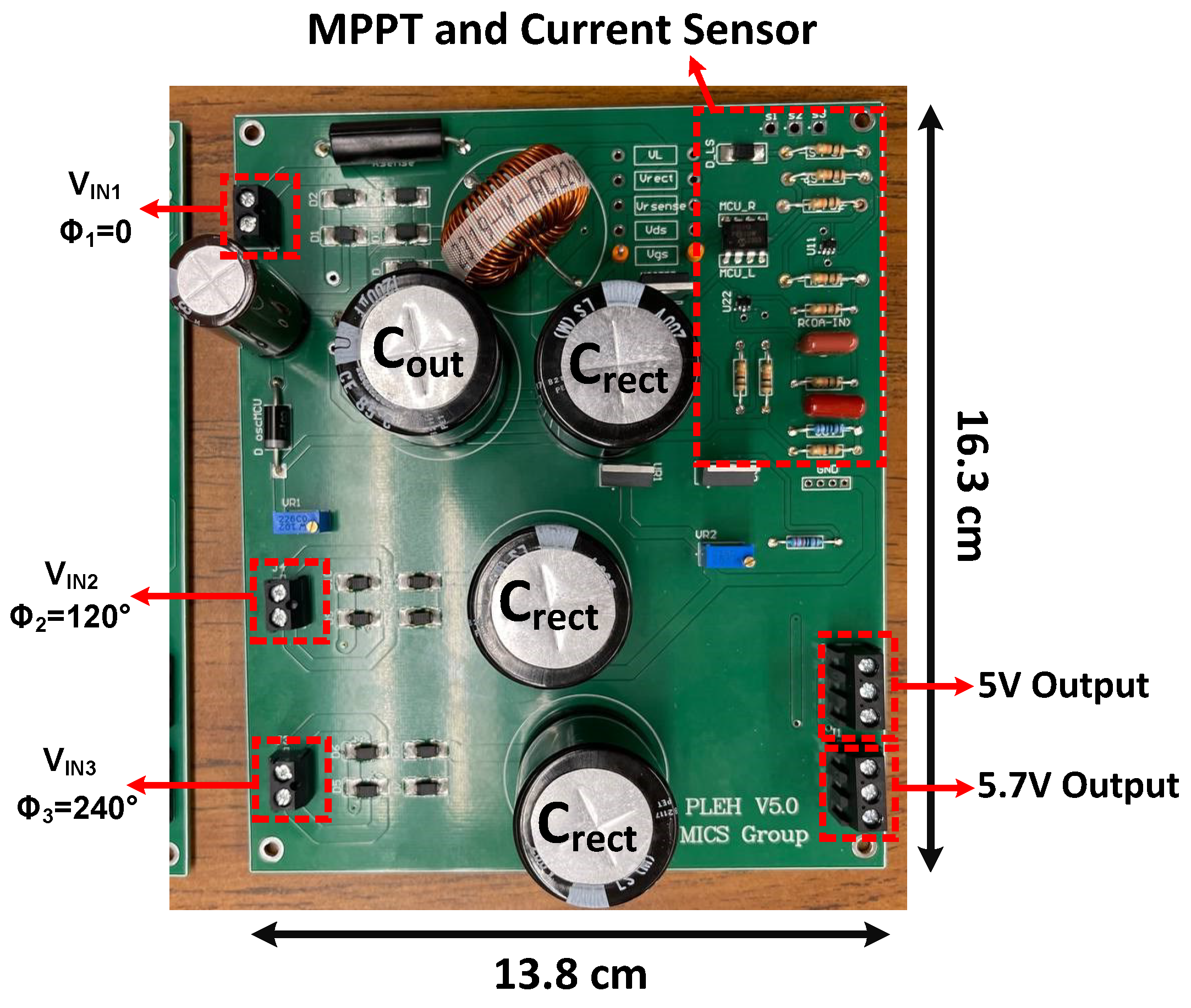
Figure 11 shows the prototyped three-phase energy harvester with dimensions of 16.3 × 13.8 cm2. The circuit is implemented on a piece of FR4 substrate material using commercial off-the-shelf (COTS) components. Special attention was given to the printed circuit board (PCB) layout to minimize parasitic effects and switching noise, which are critical for maintaining high power conversion efficiency in energy harvesting systems. The power and ground planes were designed with low impedance paths to reduce voltage drops and electromagnetic interference (EMI). The high-current paths of the buck–boost converter and rectifier were kept as short and wide as possible, and decoupling capacitors were placed close to the active devices to suppress high-frequency noise. Sensitive analog traces for the current sensor and MPPT feedback were routed separately from the switching nodes to prevent signal coupling. These layout considerations ensured stable operation and accurate sensing performance of the prototype board. These split-core silicon steel magnetic core were optimized to maximize magnetic coupling and minimize magnetizing current and core losses during bench validation. The use of split-core current transformers also facilitates field deployment as they can be conveniently clamped around existing conductors without disconnection. While the detailed optimization of the core design was beyond the scope of this paper, we acknowledge this trade-off between mechanical convenience and slight efficiency variation due to the air gap inherent in split-core configurations. The wake-up resistor R W is tuned so that the power consumption of the wake-up circuit is optimized to meet the targeted real-world application. The key circuit components are listed in Table 1.
The selection of the active components listed in Table 1 was guided by the design requirements of high efficiency, low power consumption, and stable operation under varying input conditions. The PIC16F15313 MCU was chosen for its ultra-low-power consumption, integrated 10-bit ADC, and programmable PWM module, which enable precise implementation of the MPPT algorithm and dynamic impedance control without external circuitry. The AD8628 operational amplifiers were employed in the current sensor for their low input offset voltage and high common-mode rejection ratio, ensuring accurate current measurement at small signal levels. The LM338T voltage regulators were selected to provide robust and thermally stable regulated outputs of 5 V and 5.7 V for the sensor and communication modules. Finally, the IPP110N20NAAKSA1 MOSFET offers a low on-resistance and fast switching capability, which enhances the overall conversion efficiency of the buck–boost converter. These choices collectively support efficient, autonomous, and reliable performance of the proposed three-phase energy harvesting circuit.

3.1. Magnetic Core

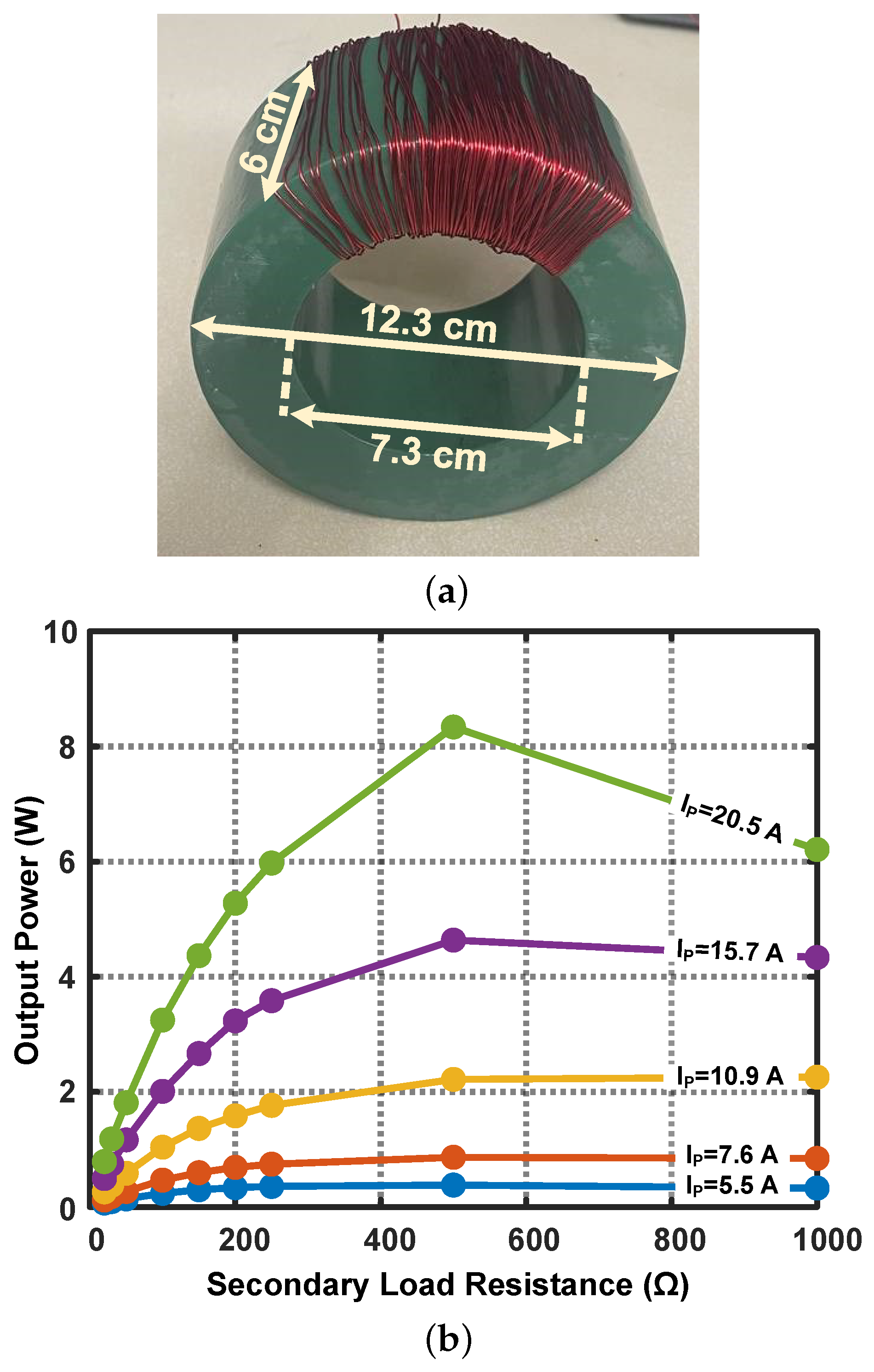
A photograph of the silicon steel core is shown in Figure 12a. The primary current is the powerline and the secondary winding has 100 turns ( N S in Figure 2). To extract the characteristics of the core, a variable resistor is connected at the secondary current of the transformer, and its resistance is swept from 10 Ω to 1 kΩ. The power delivered to the variable resistor is measured for different primary currents ( I p ) and plotted in Figure 12b. It can be seen that by increasing the primary current, the optimum load resistance of the core tends to decrease, which indicates the necessity of the MPPT to adjust the input impedance of the harvester and perform resistive impedance matching.

3.2. Current Sensor

To verify the functionality of the current sensor, the inductor’s current is swept and the output DC voltage of the sensor is measured and shown in Figure 13. It can be seen that the output voltage increases from 1.87 V to 2.09 V when the amplitude of the voltage across the sense resistor increases from 10 mV to 100 mV. The measured voltage gain of the sensor can be approximated using a line with a slope of 2.4 V / V . Since the ADC of the MCU has 10-bit resolution, this voltage gain must be sufficient to accurately track the variation in the voltage V s e n s e . As discussed earlier, the MCU reads V s e n s e every second and adjusts the duty cycle of the switching pulses and hence the input impedance of the harvester [see Figure 3].

3.3. Three-Phase Energy Harvester

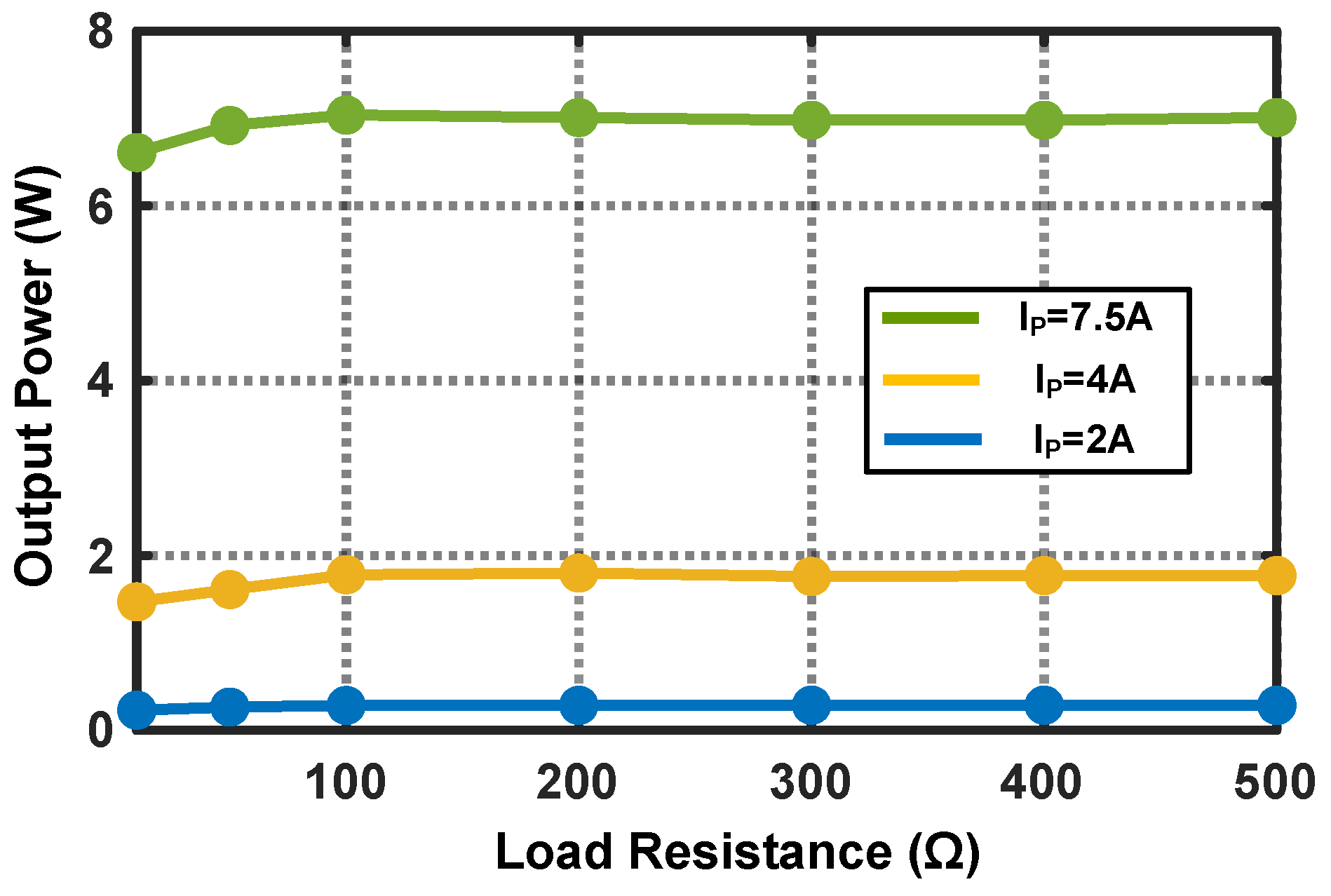
Finally, the overall performance of the three-phase energy harvester is measured by connecting three phases of a 50 Hz powerline at the input of the energy harvester and sweeping the load resistance. Figure 14 shows the power at the output of the buck–boost converter versus the load resistance. The output power remains almost constant when the load resistance changes, which shows the input impedance of the buck–boost converter to the load resistance in DCM. However, at relatively small load resistances, e.g., R L < 100 Ω , the MCU starts to push the operation mode of the buck–boost converter towards CCM when adjusting the duty cycle of the switching pulses at the switching frequency of 10 kHz. The system initiates charging once the rectifier output rises sufficiently to bias the wake-up network, after which the Zener diode regulates the control rail near 5.1 V. Under a representative operating point with a 7.5 A line current, the rectifier output reaches 5.1 V in 350 ms. The start-up capacitor is 1 μF, which stores roughly 13 μJ at 5.1 V, whereas the wake-up branch dissipates about 23 mW once conducting, amounting to ∼8 mJ over the 350 ms interval. Thus, the dominant start-up energy is expended in the wake-up path rather than in charging the reservoir, and the start-up time scales primarily with the available input power from the line current. These measurements complement the previously reported minimum activation current (≈1.3 A) and clarify the trade-off between the start-up time and quiescent consumption of the wake-up network.
The efficiency of the harvester, excluding the output voltage regulators and the power conversion efficiency, i.e., (input ac power/output DC power) of the magnetic core, is measured to be 84%, 80%, and 74.3% at 7.5 A, 4 A, and 2 A input currents, respectively. The percentage loss breakdown, shown in Table 2, represents the converter losses estimated from measured voltage and current data in combination with datasheet parameters of the active and passive components. The total converter loss was divided among MOSFET conduction and switching loss, Schottky diode forward-conduction loss, control circuit quiescent power, and residual parasitic effects such as switching overlap, wake-up circuit, capacitor and inductor ESR, and PCB copper losses. The MOSFET and diode losses were dominant at higher load currents due to increased conduction stress, while at lower input currents, the relative contribution of the control and quiescent losses became more significant because the total processed power decreased. The category labeled “Other” primarily captures transition and parasitic losses that scale with both switching frequency and device capacitance, remaining nearly constant across current levels. These results highlight that the converter efficiency is primarily limited by conduction losses in high-current operation and by control overhead in light-load conditions. All efficiency values reported exclude magnetic core and output voltage regulator losses to isolate the electrical performance of the rectifier and DC–DC converter.
Note that the buck–boost converter operates in DCM, where the inductor current is reset in each switching cycle. This operating regime limits the coupling between the instantaneous load current (i.e., wireless transceiver) and the converter’s control loop, allowing the circuit to maintain stable duty cycle operation even under transient load conditions. The output capacitors at the converter and regulator stages supply the short-term current demand, while the converter replenishes the average energy over subsequent cycles. For practical deployments, additional local decoupling near the radio module is recommended to further suppress high-frequency transients.
To the authors’ knowledge, this study represents the first demonstration of a three-phase powerline energy harvester for railroad monitoring, apart from the previously reported single-phase design in [7]. As summarized in Table 3, prior studies mainly focused on single-phase or magnetically desaturated topologies with limited scalability. The proposed harvester employs a distinct architecture consisting of three independent magnetic cores, series-connected rectifiers, a DCM buck–boost converter with adaptive MPPT, and dual regulated outputs (5 V/5.7 V). This configuration enables efficient operation across a wide input range while maintaining autonomous cold start-up capability.
Compared with previously reported designs, our system delivers 7.0 W of output power at 7.5 A, which is a substantially higher absolute power level than those of prior single-phase harvesters (e.g., 2.5 W in [17]). Although the system in [17] reports a higher peak efficiency of 97.5%, it relies on prior knowledge of the magnetic core characteristics and load conditions to configure its MPPT parameters, limiting its adaptability. In contrast, the proposed harvester incorporates an adaptive MPPT loop and an autonomous cold start-up circuit, which allow the converter to dynamically track the maximum power point without pre-programmed parameters and operate reliably under varying field conditions. These features make the proposed three-phase system more robust and scalable for high-power, real-world applications such as railroad and industrial sensor networks.

4. Conclusions

In this paper, we presented a three-phase powerline energy harvester capable of providing power for monitoring wireless sensor nodes. We discussed the detailed design of the energy harvester and the evolution toward expanding the input phases. We showed that having three phases effectively increases the harvested power when the power of a single powerline is not sufficient for the proper functionality of the WSNs. Furthermore, the MPPT block can efficiently track the output power using the introduced current sensor and adjust the duty cycle of the switching pulses and hence the input impedance of the circuit. The energy harvester was prototyped on a PCB using COTS components, and a maximum efficiency of 84% was measured for the powerline current of 20 A. In addition to the demonstrated power conversion performance, electromagnetic compatibility (EMC) considerations were also integrated into the circuit design. Since the harvester operates in proximity to high-current powerlines, the PCB layout and component placement were optimized to minimize electromagnetic interference and coupling between the high-frequency switching nodes and the sensing circuits. Differential signal routing and local decoupling capacitors were applied to reduce common-mode noise, while the ground plane continuity was maintained to suppress radiated emissions. The use of shielded magnetic cores and short current loops further improved EMC robustness. These measures ensure that the proposed three-phase energy harvester can operate reliably without introducing interference to nearby electronic systems or degrading its own sensing accuracy, making it well-suited for deployment in industrial and railway monitoring environments.

Author Contributions

Conceptualization, F.L.P., S.K.H. and D.S.H.; methodology, F.L.P. and M.S.D.; software, F.L.P. and M.S.D.; validation, F.L.P., M.S.D. and S.K.H.; formal analysis, F.L.P.; investigation, F.L.P. and S.K.H.; resources, S.K.H., J.M.K., J.L. and D.S.H.; data curation, F.L.P. and S.K.H.; writing—original draft preparation, F.L.P.; writing—review and editing, D.S.H.; visualization, F.L.P.; supervision, D.S.H.; project administration, S.K.H., J.L., J.M.K. and D.S.H.; funding acquisition, S.K.H., J.L., J.M.K. and D.S.H. All authors have read and agreed to the published version of the manuscript.

Funding

This research was supported by a grant from the R&D Program (PK2503D7) of the Korea Railroad Research Institute. This work was supported by the Technology Innovation Program (RS-2024-00412973) funded by the Ministry of Trade, Industry & Energy (MOTIE, Korea).

Institutional Review Board Statement

Not applicable.

Informed Consent Statement

Not applicable.

Data Availability Statement

The original contributions presented in this study are included in the article. Further inquiries can be directed to the corresponding author.

Conflicts of Interest

Author Jaeyun Lee was employed by Corechips Co., Ltd. The remaining authors declare that the research was conducted in the absence of any commercial or financial relationships that could be construed as a potential conflict of interest.

References

  1. Williams, A.J.; Torquato, M.F.; Cameron, I.M.; Fahmy, A.A.; Sienz, J. Survey of energy harvesting technologies for wireless sensor networks. IEEE Access 2021, 9, 77493–77510. [Google Scholar] [CrossRef]
  2. Akin-Ponnle, A.E.; Carvalho, N.B. Energy harvesting mechanisms in a smart city—A review. Smart Cities 2021, 4, 476–498. [Google Scholar] [CrossRef]
  3. Bhatt, K.; Kumar, S.; Kumar, S.; Sharma, S.; Singh, V. A review on energy harvesting technologies: Comparison between non-conventional and conceptual approaches. Energy Rep. 2024, 12, 4717–4740. [Google Scholar] [CrossRef]
  4. Sudevalayam, S.; Kulkarni, P. Energy harvesting sensor nodes: Survey and implications. IEEE Commun. Surv. Tutor. 2010, 13, 443–461. [Google Scholar] [CrossRef]
  5. Liu, J.; Zhao, Z.; Ji, J.; Hu, M. Research and application of wireless sensor network technology in power transmission and distribution system. Intell. Converg. Netw. 2020, 1, 199–220. [Google Scholar] [CrossRef]
  6. Mushtaq, M.U.; Venter, H.S.; Singh, A.; Owais, M. Advances in energy harvesting for sustainable wireless sensor networks: Challenges and opportunities. Hardware 2025, 3, 1. [Google Scholar] [CrossRef]
  7. Hosseini, S.H.; Greer, J.; Pour, F.L.; Ha, D.S. Powerline Energy Harvesting with Maximum Power Point Tracking for a Wide Current Range. In Proceedings of the 2023 IEEE International Symposium on Circuits and Systems (ISCAS), Monterey, CA, USA, 21–25 May 2023; pp. 1–5. [Google Scholar] [CrossRef]
  8. Wang, J.; Kim, J.; Ha, D.S. Powerline energy harvesting circuit with a desaturation controller for a magnetic core. In Proceedings of the IEEE International Midwest Symposium on Circuits and Systems (MWSCAS), Lansing, MI, USA, 9–11 August 2021; pp. 220–223. [Google Scholar] [CrossRef]
  9. Zhuang, Y.; Xu, C.; Yuan, S.; He, C.; Chen, A.; Lee, W.W.; Zhou, J.; Huang, Y. An improved energy harvesting system on power transmission lines. In Proceedings of the 2017 IEEE Wireless Power Transfer Conference (WPTC), Taipei, Taiwan, 10–12 May 2017; pp. 1–3. [Google Scholar] [CrossRef]
  10. Li, P.; Wen, Y.; Zhang, Z.; Pan, S. A high-efficiency management circuit using multiwinding upconversion current transformer for power-line energy harvesting. IEEE Trans. Ind. Electron. 2015, 62, 6327–6335. [Google Scholar] [CrossRef]
  11. Yuan, S.; Huang, Y.; Zhou, J.; Xu, Q.; Song, C.; Thompson, P. Magnetic field energy harvesting under overhead power lines. IEEE Trans. Power Electron. 2015, 30, 6191–6202. [Google Scholar] [CrossRef]
  12. Wang, W.; Huang, X.; Tan, L.; Guo, J.; Liu, H. Optimization design of an inductive energy harvesting device for wireless power supply system overhead high-voltage power lines. Energies 2016, 9, 242. [Google Scholar] [CrossRef]
  13. Zhang, J.; Tian, X.; Li, J.; Yan, D. A novel electromagnetic energy harvester based on double-ring core for power line energy harvesting. J. Circuits Syst. Comput. 2020, 29, 2050265. [Google Scholar] [CrossRef]
  14. Xu, C.; Wang, W.; Su, W.; Duan, M.; Hu, M. Anti-saturation and power decoupling control of multiwinding energy harvester based on magnetomotive force compensation. IEEE Trans. Ind. Inf. 2023, 19, 10555–10563. [Google Scholar] [CrossRef]
  15. Jung, S.; Kim, S.; Cho, W.; Lee, K. Development of highly efficient energy harvester based on magnetic field emanating from a household power line and its autonomous interface electronics. IEEE Sens. J. 2023, 23, 6607–6615. [Google Scholar] [CrossRef]
  16. Andres, C.; Fritsch, M.; Wolter, M. Inductive energy harvester with saturation-controlled maximum power point tracking. In Proceedings of the IEEE Power & Energy Society General Meeting (PESGM), Seattle, WA, USA, 21–25 July 2024; pp. 1–5. [Google Scholar] [CrossRef]
  17. Li, Y.; Duan, N.; Liu, Z.; Hu, J.; He, Z. Impedance-matching-based maximum power tracking for magnetic field energy harvesters using active rectifiers. IEEE Trans. Ind. Electron. 2022, 70, 10730–10739. [Google Scholar] [CrossRef]
  18. Yablokov, A.A.; Panashchatenko, A.V.; Tychkin, A.R. Determining the characteristics of current transformers required for correct operation of relay protection devices. In Proceedings of the 6th International Youth Conference on Radio Electronics, Electrical and Power Engineering (REEPE), Moscow, Russia, 29 February–2 March 2024; pp. 1–5. [Google Scholar] [CrossRef]
  19. Huang, X.; Wang, H.; Li, Q.; Yang, N.; Ren, T.; Peng, Y.; Li, H. Electrical characteristics of new three-phase traction power supply system for rail transit. Railw. Eng. Sci. 2022, 31, 75–88. [Google Scholar] [CrossRef]
  20. Kim, J.; Kwon, I. Design of a high-efficiency DC-DC boost converter for RF energy harvesting IoT sensors. Sensors 2022, 22, 10007. [Google Scholar] [CrossRef]
  21. Kong, N.; Ha, D.S.; Erturk, A.; Inman, D.J. Resistive impedance matching circuit for piezoelectric energy harvesting. J. Intell. Mater. Syst. Struct. 2010, 21, 1293–1302. [Google Scholar] [CrossRef]
  22. Pande, J.; Nasikkar, P.; Kotecha, K.; Varadarajan, V. A review of maximum power point tracking algorithms for wind energy conversion systems. J. Mar. Sci. Eng. 2021, 9, 1187. [Google Scholar] [CrossRef]
  23. Jackson, H.W. Introduction to Electronic Circuits; Prentice-Hall: Englewood Cliffs, NJ, USA, 1959. [Google Scholar]
  24. Brufau-Penella, J.; Puig-Vidal, M. Piezoelectric energy harvesting improvement with complex conjugate impedance matching. J. Intell. Mater. Syst. Struct. 2009, 20, 597–608. [Google Scholar] [CrossRef]
  25. De Brito, M.A.G.; Galotto, L.; Sampaio, L.P.; de Azevedo e Melo, G.; Canesin, C.A. Evaluation of the main MPPT techniques for photovoltaic applications. IEEE Trans. Ind. Electron. 2012, 60, 1156–1167. [Google Scholar] [CrossRef]
  26. Shi, X.; Cai, M.; Jiang, Y. Key role of cold-start circuits in low-power energy harvesting systems: A research review. J. Low Power Electron. Appl. 2024, 14, 55. [Google Scholar] [CrossRef]
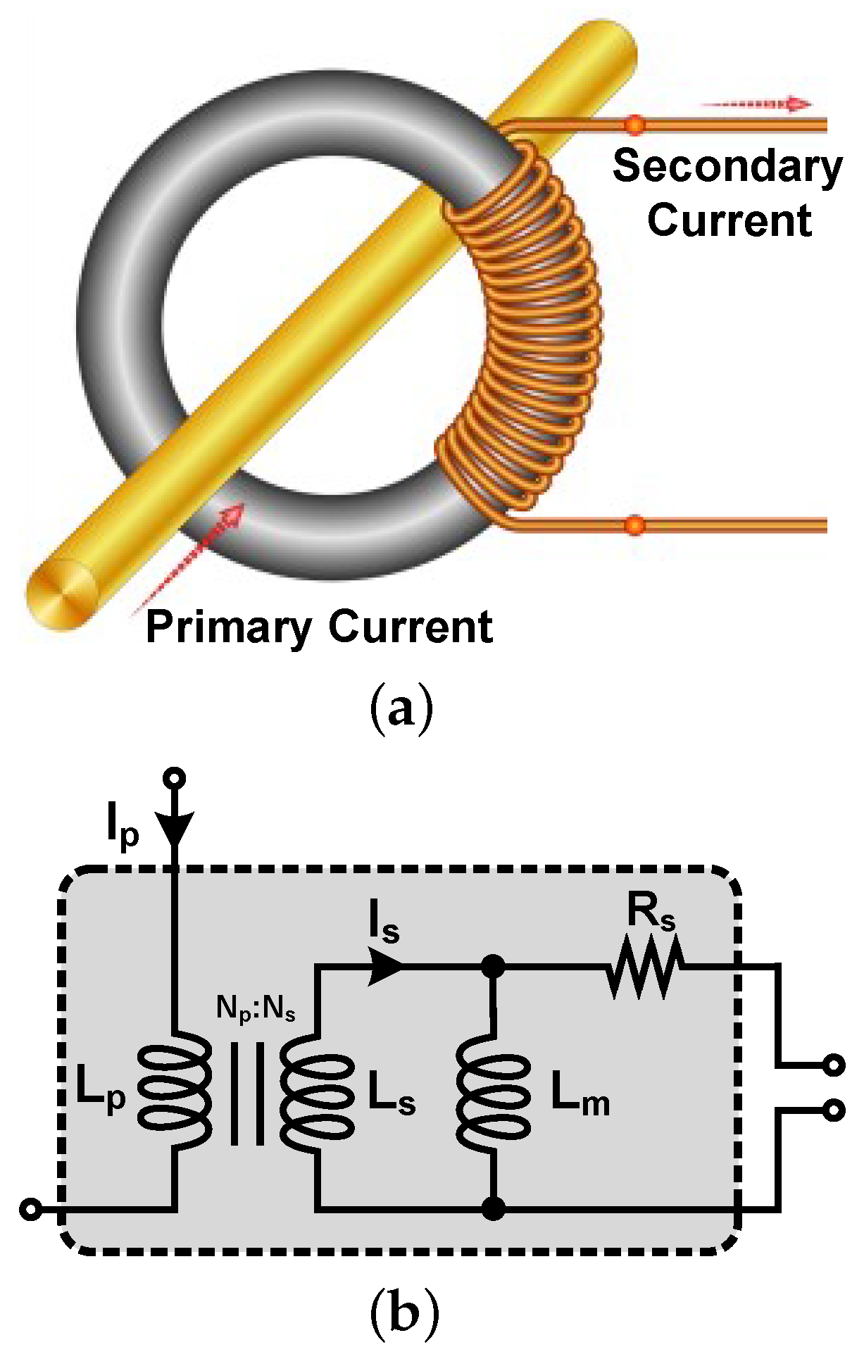
Figure 1. (a) Magnetic core and (b) its equivalent circuit.
Applsci 15 11954 g001
Figure 2. Simplified schematic of the introduced energy harvester.
Applsci 15 11954 g002
Figure 3. Simulated input impedance of the energy harvester ( R i n ) as a function of the input impedance of the buck–boost converter ( R B B ).
Applsci 15 11954 g003
Figure 4. Simplified schematic of the harvester incorporating a current sensor to sense the inductor current I L .
Applsci 15 11954 g004
Figure 5. Output voltage, the duty cycle of the switching pulses ( V G ), inductor’s current, and the input power to the buck–boost converter over the coarse and fine-tuning windows.
Applsci 15 11954 g005
Figure 6. Flowchart of the designed MPPT algorithm. Flag indicates the direction of power change; Counter tracks the number of consecutive iterations; R denotes the size of the duty-cycle adjustment step; and D is the duty cycle of the converter.
Applsci 15 11954 g006
Figure 7. (a) Schematic diagram of the current sensor, and (b) its simulated frequency response.
Applsci 15 11954 g007
Figure 8. Simplified schematic of the harvester equipped with the wake-up circuit.
Applsci 15 11954 g008
Figure 9. (a) Series voltage and (b) parallel current configurations.
Applsci 15 11954 g009
Figure 10. Complete schematic of the energy harvester.
Applsci 15 11954 g010
Figure 11. Photograph of the prototyped energy harvesting board.
Applsci 15 11954 g011
Figure 12. (a) Silicon steel core and (b) measured power at its secondary current for different primary currents.
Applsci 15 11954 g012
Figure 13. The voltage gain of the current sensor.
Applsci 15 11954 g013
Figure 14. Measured output power of the energy harvester against the load resistance.
Applsci 15 11954 g014
Table 1. List of components.
ComponentModelKey Parameters
Schottky DiodesRB068L150DDTE25 V F = 0.74 V @ I F = 2 A , I R = 0.1 μ A @ V R = 150 V
Zener Diode D W CZ5338B TR PBFREE V Z = 5.1 V @ I Z = 240 mA, R Z = 1.5   Ω , I Z , m a x = 930 mA
Switching Transistor M 1 IPP110N20NAAKSA1 R D S ( o n ) = 9.9 mΩ, V G S ( t h ) = 3 V @ V D S = V G S , I D ( l e a c k ) = 1   μ A
MCUPIC16F15313 I D D = 2.5 mA @ V D D = 5.1 V, f = 16 MHz, I s l e e p = 140 nA
Operational AmplifiersAD8628 E n , p p = 0.5   μ V @ f < 10 Hz, A V O = 145 dB, I D = 0.85 mA @ V D D = 5.1 V
Voltage RegulatorsLM338T I o u t = 5 A @ V o u t = 5 / 5.7 , E n , o u t < 3 × 10 5   V o u t @ 0.3 V < V i n < 40 V
Wake-up Capacitor C W C W = 1   μ F
Rectifier Capacitor C r e c t C r e c t = 1.2 mF
Output capacitorC C = 1.2 mF
Buck–Boost InductorL L = 390   μ H
Table 2. Measured converter efficiency and estimated electrical loss distribution at three input currents.
Input Current I p (A)Output Power (W)Efficiency (%)MOSFET Loss (%)Rectifier Loss (%)Control Circuit (%)Other a (%)
7.57.0084.09.05.01.50.5
4.01.8080.07.06.03.53.5
2.00.2974.35.56.57.06.7
a “Other” includes switching losses (transition overlap and gate-drive), wake-up circuit, capacitor/inductor ESR, and PCB/wiring losses. Note: Efficiencies exclude magnetic core losses to isolate the rectifier + DC–DC converter performance.
Table 3. Comparison of energy harvesting schemes.
Reference[7][8][16][17]This Work
SchemeMC 1/Rect./DCM Conv./Output Reg.MC/Rect./Mag. Desat.MC/Rect./DC-DC Conv./Output Reg.MC/Rect./MPPTMC/Rect./DCM Conv./Output Reg.
Impedance MatchingYesNoYesYesYes
Cold Start-upNoNoNoNoYes
Line Current (RMS)20 A25 A100 A80 A7.5 A/3-Phases
Line Frequency60 Hz50 Hz50 Hz50 Hz50 Hz
Load Voltage or Resistance250 Ω 1.1 kΩNA 2800 Ω 5 V/5.7 V
Harvested Power7 W65 mW1 W2.5 W7 W
Efficiency 370%64%NA97.5%84%
1 MC denotes magnetic core. 2 NA denotes not available. 3 Excludes the loss of the magnetic core.
Disclaimer/Publisher’s Note: The statements, opinions and data contained in all publications are solely those of the individual author(s) and contributor(s) and not of MDPI and/or the editor(s). MDPI and/or the editor(s) disclaim responsibility for any injury to people or property resulting from any ideas, methods, instructions or products referred to in the content.