Abstract
Fault-tolerant strategies have received increasing attention recently, as reliability requirements have become more stringent. This has drawn significant attention to multiphase machines, due to their inherent fault-tolerance capabilities. Although multiphase machines have been extensively studied as motors since the late 1960s, their use as generators is still in its infancy. Moreover, research on their fault-tolerant capabilities and impact on the power grid remains very limited. With the global expansion of the wind energy sector, the continuous increase in turbine capacities, and the shift in wind energy markets toward offshore wind farms, there is a growing need for studies that investigate the integration of multiphase machines with fault-tolerant strategies and that evaluate their performance and impact on the grid. Therefore, this paper aims to investigate a wind energy conversion system (WECS) based on a five-phase permanent magnet synchronous generator (PMSG) and to evaluate its performance under two fault scenarios: a single-phase open-circuit fault and a double-phase open-circuit fault. A fault-tolerant control strategy is applied in both cases to evaluate its effectiveness under varying wind speeds. The study is carried out using simulation tools developed in MATLAB/Simulink.
1. Introduction
Multiphase machines (MPMs) have attracted increasing interest due to their advantages over conventional three-phase machines, including reduced current per phase, lower torque ripple, and enhanced fault tolerance. Although MPMs have been studied since the late 1960s, when five-phase inverter-fed induction motors were first investigated [1], research interest remained limited for several decades due to the dominance of three-phase machines [2]. However, since the beginning of this century, interest in MPMs has grown rapidly, driven by the development of various applications requiring high power and high reliability, such as electric propulsion, traction, and the concept of more-electric aircraft [3].
More recently, MPMs have emerged as promising candidates for renewable energy systems, such as offshore wind turbines in wind energy conversion systems (WECS), to exploit wind energy in an efficient and cost-effective way. The continuous increase in the size and capacity of wind turbines, along with the shift toward offshore wind power plants, has further underscored the need for highly reliable machine technologies worldwide.
Offshore wind turbines are installed in remote locations and operate in harsh environments, increasing the likelihood of electrical faults. These faults are categorized into two types: short-circuit and open-circuit faults. While protection devices typically isolate short circuits by converting them into open-circuit faults [4,5], the disconnection resulting from a faulty turbine requires immediate maintenance. This poses a problem for offshore wind farms and the electrical grid as the penetration of offshore wind power increases, since harsh marine conditions complicate maintenance operations, leading to extended downtime and economic losses. As most controller designs become complicated under open-phase fault conditions, further work on fault-tolerant control strategies has become essential to ensure reliable operation and minimize the impact of faults [6]. Several studies have proposed fault-tolerant control strategies for direct-drive three-phase permanent magnet synchronous generators (PMSGs) [7,8,9,10,11]. However, these strategies often require additional hardware or complex control schemes, as three-phase machines cannot maintain a constant magnetomotive force (MMF) when one or more phases are disconnected. Moreover, most strategies are limited to a single-phase fault, meaning that if more than one phase is disconnected, the system will cease to operate without any ability to continue. In contrast, multiphase machines have the ability to continue operation in the event of a fault without the need for additional hardware, relying solely on redistributing currents in the healthy phases to compensate for the missing phase(s).
In previous research, several studies have addressed the use of multiphase generators in wind energy conversion systems (WECS) and their fault-tolerant capabilities [12]. However, the investigation of these capabilities is still limited, and it is noted that there is a significant focus on multiphase machines composed of multiple sets of three-phase windings, such as six-phase [13,14,15,16,17] and eighteen-phase machines [18]. Although these topologies provide strong fault tolerance, they require multiple converters, which increase system cost, size, and control complexity [12,18].
On the other hand, five-phase generators offer a practical compromise: they maintain strong fault-tolerant capability while maintaining a relatively simple and cost-effective converter structure [19,20,21]. Nevertheless, most existing studies on the fault-tolerant operation of five-phase PMSGs assume a constant generator speed, which is suitable for marine power applications where the variation in marine current speed is minimal. However, in wind energy, wind speed has an intermittent nature, which can change rapidly and affect system operation after applying the fault-tolerant strategy. This means that wind speed should be taken into account when studying these strategies.
In addition to fault-tolerant control, predictive and proactive maintenance strategies have recently gained significant attention for improving the reliability of wind energy systems. These approaches aim to detect or anticipate faults before they cause critical failures, thereby reducing downtime and maintenance costs. For instance, the authors in proposed an early warning method for detecting power cable weaknesses in offshore wind farms, while in [22], the authors developed a cost-effective maintenance plan for multiple defect types in wind turbine blades. More recent studies [23,24,25,26,27] have expanded this field through comprehensive reviews, data-driven condition monitoring, and predictive maintenance frameworks for offshore wind turbines. Although these approaches significantly enhance preventive maintenance and reliability management, they do not directly ensure continuous operation once a fault occurs. In contrast, the fault-tolerant strategy proposed in this paper complements such predictive methods by maintaining generator operation and grid stability during faulted conditions. Hence, this paper aims to present a complete modeling and simulation of a WECS with a direct-drive five-phase PMSG, in addition to applying a fault-tolerant strategy under two fault conditions: a single-phase fault (Phase ‘a’) and a double-adjacent fault (Phase ‘a’ and Phase ‘b’). The study investigates the effectiveness of the fault-tolerant control strategy in both scenarios and evaluates the impact of wind speed variations on both the machine and grid sides.
The main motivation behind this work is to enhance the reliability of wind energy conversion systems by ensuring continuous power generation even under faulted conditions. Although several studies have examined fault-tolerant strategies for three-phase systems, these approaches often require additional hardware and are limited to the constant-speed operation of motors. In contrast, the performance of five-phase PMSGs under variable wind speeds and open-phase faults remains insufficiently explored. To address this gap, this study presents a comprehensive modeling and analysis of a grid-connected five-phase PMSG equipped with a fault-tolerant control strategy. The proposed approach enables current redistribution among the healthy phases to maintain a constant magnetomotive force and stable operation during single and double-phase open-circuit faults. Simulation results confirm that the strategy effectively reduces torque ripple, DC-link voltage oscillations, and grid current harmonics across different wind speeds, demonstrating its potential to significantly improve the reliability and stability of wind energy systems.
The remainder of this paper is organized as follows: Section 2 introduces the modeling of the wind turbine, five-phase PMSG, and back-to-back converter control system. Section 3 presents the fault-tolerant strategy, including the derivation of the new phase currents required to maintain a constant MMF under fault conditions. Section 4 discusses the simulation results and evaluates system performance under single-phase and double-phase fault scenarios at different wind speeds. Finally, Section 5 concludes the paper and outlines potential directions for future research.
2. System Model
Figure 1 shows the general scheme of a grid-connected wind energy conversion system, which is addressed in this paper under both healthy and faulty conditions. The system includes a wind turbine, a five-phase permanent magnet synchronous generator (PMSG), and bidirectional back-to-back converters.
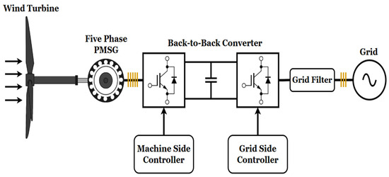
Figure 1.
Grid-connected WECS with direct-drive five phase PMSG.
2.1. Wind Turbine Modelling
The wind turbine model follows the representation presented in previous studies, such as the study in [28]. The turbine captures wind energy through its blades and converts it into mechanical power, which is mathematically expressed in Equation (1) below.
where ρ is the air density, R is the blade radius, Vw is the wind speed, Cp is the power coefficient, β is the pitch angle, and λ is the tip-speed ratio, which is expressed mathematically as shown in Equation (2).
where is the rotor speed in radians per second.
The power coefficient (Cp), which represents the efficiency of power conversion, is a function of the tip-speed ratio (λ) and the pitch angle (β). This coefficient is typically determined through experimental testing conducted by the manufacturer and provided in the wind turbine datasheet. For modeling and simulation purposes, it can be expressed mathematically as shown in Equation (3).
The constants C1 to C6 depend on the type of the turbine and are determined by the manufacturer or through a fitting process, as described in [29,30]. In this work, the approach presented in [28] is adopted to represent the value of Cp and the coefficients C1 to C6 which are listed in Table 1.

Table 1.
Cp value and coefficients C1 to C6.
The parameter λi in the equation above is mathematically defined in Equation (4). Its main purpose is to combine the effects of both the tip-speed ratio λ and the pitch angle (β), thereby simplifying the expression of the power coefficient (Cp).
Figure 2 illustrates the relationship between the power coefficient and the tip-speed ratio for different pitch angles. It is clear from the graph that there is only one value of the tip-speed ratio that maximizes the power coefficient, referred to as the optimum tip-speed ratio. To extract the maximum power from the wind at varying wind speeds, the turbine must operate at this optimum ratio, which is achieved by setting the rotor speed at its reference value as defined in Equation (5). This principle is known as maximum power point tracking (MPPT). In this study, the black curve in the figure is used for all simulation scenarios. The maximum power coefficient in this case is 0.48, corresponding to a tip-speed ratio of 8.1 and 0° pitch angle. This curve is selected because the simulations are conducted under the rated operating conditions of the wind turbine, where the pitch angle is known to remain at zero degree.
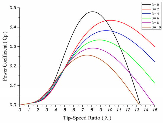
Figure 2.
Power coefficient (Cp) vs. Tip-speed Ratio (λ).
Equation (6) represents the mechanical equation of the wind turbine system and is expressed as follows:
where JT represents the total inertia of the wind turbine and generator, B is the damping coefficient, Tm is the mechanical torque of the turbine, and Te is the electromagnetic torque of the generator.
2.2. Five Phase Permanent Magnet Synchronous Machine (PMSM) Model
This subsection presents the detailed mathematical model of a five-phase Permanent Magnet Synchronous Machine (PMSM). The machine considered in this study is assumed to have a sinusoidal back electromotive force (EMF), while the effects of magnetic saturation and rotor saliency are neglected. The five-phase PMSM is designed with stator windings spatially displaced by 72° from each other, as shown in Figure 3.
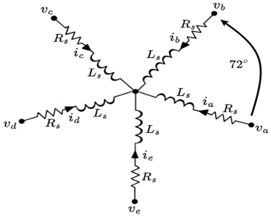
Figure 3.
Five-phase PMSM stator windings (star connection).
In the natural reference frame, the stator voltage equation of the five-phase PMSM can be expressed as shown in Equation (7). The stator voltage consists of the resistive voltage drop and the time derivative of the stator flux linkage [31,32].
where:
- is the stator voltage vector represented as
- is the stator voltage vector represented as
- is the diagonal stator resistance matrix expressed in Equation (8)
- is the stator flux linkage vector defined in Equation (9)
The electromagnetic torque is derived by using the magnetic co-energy method as given in Equation (11) where below represents the number of pole pairs:
Based on the above analysis, it can be seen that the mathematical model is complex. Hence, vector space decomposition theory is used to simplify the machine model, which states that five-phase machines can be decomposed into two orthogonal subspaces and one zero subspace in the stationary reference frame [6]. From a mathematical point of view, the resulting subspaces are orthogonal, which means that they are decoupled from each other, allowing for independent control of their components. In the context of electrical machines, these subspaces decouple the fundamental components that contribute to electromechanical energy conversion from the components that do not. The Clarke transformation matrix for converting the machine variables from the natural reference frame to the stationary reference frame is shown in Equation (12).
From the matrix above, the first two rows represent the components of the first subspace, which include the fundamental components denoted as . These components are the only ones that contribute to the useful electromechanical energy conversion in machines with sinusoidal distribution. The third and fourth rows represent the components of the extra subspace, which include the higher-order harmonics denoted as . These components do not contribute to electromechanical energy conversion and only produce losses. For the purpose of high efficiency, these components are controlled to be zero as possible. The last row represents the components of the zero-sequence subspace, and these components are equal to zero in any machine with an odd number of phases and an isolated neutral point. Another transformation is applied to convert these components from the stationary reference frame to the synchronous reference frame, which presents the variables as DC components (constant values) and allows for applying the vector control theory. This is achieved by using the Park transformation, as given in Equation (13).
In the synchronous reference frame, the voltage equations can be expressed as given in Equation (14) through (17).
where:
- and are the phase voltages in d1q1 reference frame
- and are the phase currents in d1q1 reference frame
- and are the phase voltages in d2q2 reference frame
- and are the phase currents in d2q2 reference frame
- and are d1-axis and q1-axis inductances, respectively.
- and are d2-axis and q2-axis inductances, respectively.
The electromagnetic torque can be expressed as shown in Equation (18). Since Ldm = Lqm, the torque becomes a function of the q-axis current, similar to that of a three-phase machine.
2.3. Back-to-Back Converter Control
The wind energy conversion system is connected to the electrical grid using back-to-back converters that control the operation of the system, ensuring efficient grid integration. The configuration of back-to-back converters includes two converters, known as the machine-side converter (MSC) and the grid-side converter (GSC), with a DC link between them. The main goal of the MSC is to control the torque and speed of the generator to operate at the optimum values, enabling the extraction of maximum power under all wind speed conditions [33]. This is achieved by applying field-oriented control (FOC), which includes two control loops. The first loop is the speed control loop, which generates the reference q-axis current by comparing the actual speed with the optimum reference speed. The second control loop is the current control loop, which generates the reference currents based on the q-axis reference current, while the other currents are given zero reference to maximize torque and reduce the losses produced by the extra subspace. Then, by using a PI controller, the actual currents are adjusted to follow their references. On the other hand, the grid-side converter controls the DC-link voltage and the active and reactive power injected into the grid. This is achieved by using voltage-oriented control (VOC), which is similar to the aforementioned FOC technique. In this control, one outer loop is used to control the DC-link voltage and generate the d-axis reference current. This reference is used in the first inner current control loop, which adjusts the d-axis current to follow its reference. The second inner current control loop controls the q-axis current to be zero, thereby achieving zero reactive power and unity power factor.
In conventional wind turbine systems, pitch angle control is typically used to regulate mechanical power and limit turbine speed at high wind velocities by adjusting the blade angle. However, since the focus of this work is on the electrical fault-tolerant behavior of the generator and converter, the pitch control is assumed to remain constant throughout the simulations. The maximum power point tracking (MPPT) algorithm governs the operating point within the electrical subsystem, while the aerodynamic input is modeled at a fixed blade pitch angle corresponding to sub-rated operating conditions. This assumption isolates the effects of electrical faults and simplifies the evaluation of the proposed fault-tolerant control strategy. The control of the back-to-back converters is shown in Figure 4 in full detail.
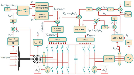
Figure 4.
Control of Back-to-Back Converters (the sign * refers to the reference values).
3. Fault Tolerant Strategy
The fault-tolerant strategy applied to the five-phase PMSG is presented to maintain a constant magneto-motive force (MMF) under open-phase faults, allowing the generator to continue operating with acceptable performance. In a three-phase machine, when one phase is disconnected, the remaining two-phase currents are no longer independent. As a result, the machine loses its ability to generate the required rotating MMF, and the installation of additional hardware or complex reconfiguration techniques becomes necessary to restore operation [6]. In contrast, a multiphase machine possesses extra degrees of freedom due to the additional available subspace, allowing it to maintain a constant MMF by redistributing currents among the healthy phases without requiring extra hardware.
Under normal operating conditions, the MMF in the five-phase permanent magnet synchronous machine with sinusoidal distribution can be expressed as given in Equation (19). It is clear that this equation represents the components of the first subspace (α1β1) as described in the previous section
where Im represents the magnitude of the phase current with θe = ωt. Separating the real and imaginary parts of Equation (19) yields Equations (20) and (21).
When a fault occurs and phase ‘a’ is disconnected, the corresponding phase current is set to zero. To determine the new values of the remaining currents, the above equations are solved while considering that the sum of all currents is zero, as shown in Equation (22).
Mathematically, the solution of these equations under this condition is infinite because they involve four variables. Therefore, an additional constraint must be introduced to obtain a unique solution, and this constraint is defined according to the intended operating objective [34,35]. For example, if maximizing torque is the priority, the constraint requires balanced phase currents. In this study, since the system uses a direct-drive configuration where torque is of primary importance, the chosen constraint should satisfy the following relation.
Based on this constraint, the following equations present all the steps in detail to calculate the new set of currents. First, the equations should be written with the substitution of a zero value in place of phase ‘a’, as shown in Equations (24) and (25).
To simplify the equations, a common factor can be taken, as shown in Equations (26) and (27).
By substituting Equation (23) into Equations (26) and (27), the new set of equations can be written as shown in Equations (28) and (29).
By rearranging and simplifying the equations, the following can be obtained as shown in Equations (30) and (31)
Now, since and are known, the value of can be determined by adding both equations as given in Equation (32), and it should be clear that all currents will have the same amplitude according to the previously applied constraint, and the only difference lies in the phase shift of each phase.
This equation can be represented in the form of where and . Therefore, can be obtained as follows:
The same process can be repeated for all other currents, and the results are shown below.
The expressions indicate that the new currents in the remaining healthy phases should increase by 1.382 times the original current values before the fault in order to compensate for the missing phase and maintain a constant MMF, allowing the machine to operate under stable conditions with lower torque ripples. The vector diagram of the new currents in the remaining healthy phases is shown in Figure 5.
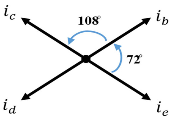
Figure 5.
Phase Current Vectors Under Fault-tolerant Operation during Single-Phase Fault.
The second case considered in this paper occurs when both phase ‘a’ and phase ‘b’ are disconnected. By following the same steps applied for the single-phase fault, the new currents that allow the machine to continue operating with the same MMF as before the fault can be determined. The real and imaginary parts of the MMF are expressed as a new set of Equations (37) and (38).
To determine the new current values, these equations need to be solved while taking into consideration that the sum of all currents is equal to zero, as shown in Equation (39).
By using Equation (39), it can be seen that and by substituting this relation in Equation (37), can be calculated as shown in the following steps:
To determine and , Equation (40) is substituted into Equation (38). By simplifying the equation, can be determined as shown in Equation (41) below:
Now, since and are known, and can be calculated as shown in the following steps. For , the two equations are added resulting in the relation given in Equation (42):
For , the two equations are subtracted which results in the following relations:
Therefore, and can again be represented as shown below in Equations (44) and (45):
The results indicate that the new and should increase by 2.236 times the original current, while should increase by 3.615 times in order to maintain the operation and generate the same MMF produced in healthy conditions. It can be seen that currents increase to higher values compared to single-fault conditions. The vector diagram for the new currents in the remaining phases is shown in Figure 6.
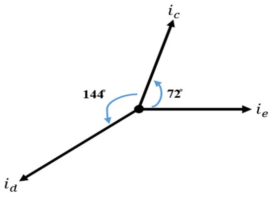
Figure 6.
Phase Current Vectors Under Fault-tolerant Operation during Double-Phase Fault.
Figure 7 illustrates the complete sequence of operations within the proposed fault-tolerant control strategy. This framework can be applied to various fault scenarios through different combinations of control constraints. Under normal operating conditions, the system generates the normal current references corresponding to balanced and healthy operation. When a fault is detected, however, the control algorithm recalculates new reference currents based on the fault type and the selected constraints. By selecting and combining these constraints, the control strategy can effectively enhance system performance, ensuring stable operation under fault conditions.
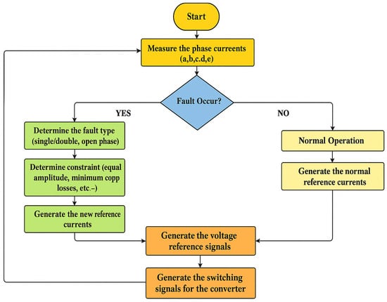
Figure 7.
Fault tolerant strategy flowchart.
4. Results and Discussion
MATLAB/Simulink software (R2023b) has been used to implement the system and test the fault-tolerant strategy. The data used in the simulation are shown in Table 2. The parameters listed in the table were selected based on typical values reported for medium-scale direct-drive wind turbines [33,36]. The electrical parameters, such as stator resistance, inductance, and flux linkage, correspond to a 2 MW-class PMSG model used in previous studies, while the mechanical parameters, including air density and blade radius, reflect typical wind turbine specifications. The simulation cases were designed to represent realistic operating scenarios under variable wind speeds. Two average wind speeds, 9 m/s and 11 m/s, were selected to represent moderate- and high-wind conditions, respectively, while maintaining generator operation within its rated limits.

Table 2.
Simulation Parameters.
The system is tested under single-phase and double-phase fault conditions. The simulation starts with a wind speed of 9 m/s, and the period is set to 5.5 s, under normal operating conditions continuing for the first 1 s. At t = 1 s, an open-phase fault occurs. At t = 1.5 s, the fault-tolerant strategy is applied and remains active until the end of the simulation period. During this interval, different wind speeds are applied to the system, as shown in Figure 8. To simplify the results, the discussion is divided into three parts: the first part discusses the single-phase fault under constant speed, the second part discusses the double-phase fault under constant speed, and the last part covers the wind speed variation for both faults and analyzes the impact on the electrical grid and machine torque during these changes.
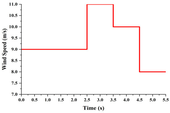
Figure 8.
Wind Speed profile.
4.1. Single-Phase Fault
Under normal operating conditions, the machine operates with balanced five-phase currents separated from each other by 72 degrees. When a fault occurs and phase ‘a’ is disconnected, the currents become unbalanced, which deteriorates the performance of the machine and negatively affects the overall system performance. However, the fault-tolerant strategy seeks to restore the currents to balanced operation, stabilizing the system and improving its performance under such conditions. Figure 9 shows the stator current waveforms under normal operating conditions, fault conditions, and with the fault-tolerant strategy applied. As can be seen from the figures, after applying the fault-tolerant strategy, the current amplitudes increase by 1.382 times the original currents to compensate for the missing phase(s). The stator currents accordingly return to a balanced condition as a result of applying the fault-tolerant strategy.
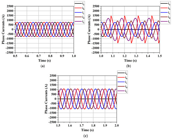
Figure 9.
Stator current waveforms: (a) normal operation; (b) single-phase fault operation; (c) fault tolerance operation.
Figure 10 shows the electromagnetic torque, rotor speed, and DC-link voltage. It is clear from the figures that the fault causes high fluctuations in all of these variables due to the unbalanced condition resulting from the loss of phase ‘a’. Nevertheless, all variables follow their reference values. From Figure 10a, it can be seen that the torque ripples increase significantly from around 2.73% under normal conditions to approximately 49% at a wind speed of 9 m/s when the fault occurs at time t = 1 s. However, the torque ripples decrease to around 3% after applying the fault-tolerant strategy starting from time t = 1.5 s, which is close to the original torque ripple level. The DC-link voltage also decreases after applying the fault-tolerant algorithm, dropping by approximately 70% which decrease the power fluctuation on the grid-side.
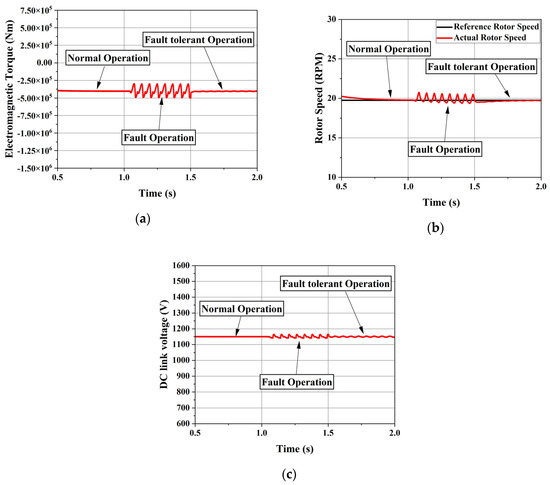
Figure 10.
System variables for single-phase open-circuit fault: (a): electromagnetic torque; (b): Rotor Speed; (c): DC link voltage.
Figure 11 shows the grid current during normal operation, fault conditions, and fault-tolerant control. When a fault occurs, the harmonics in the grid current increase from approximately 2.94% to around 11.54% due to the unbalanced operation of the generator and the fluctuation of the DC-link voltage. However, after applying the fault-tolerant strategy, the grid current harmonics decrease significantly to about 4.89% which enhance the system stability.
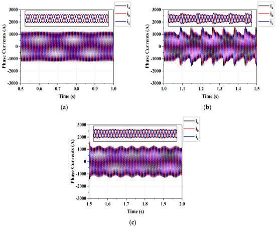
Figure 11.
Grid currents: (a): normal operation; (b): single-phase open circuit fault operation; (c): fault tolerance operation.
4.2. Double Phase Fault
In this subsection, the double-phase fault is analyzed under a constant wind speed of 9 m/s. Figure 12 shows the machine currents under fault conditions and under fault-tolerant control. The machine is observed to continue operating with unbalanced currents, exhibiting a relatively high current in phase ‘d’ which is around 3.615 times the original current. This scenario represents a critical situation, as unbalanced operation leads to harmonic injection into the grid. Moreover, the current magnitude may exceed its rated limit as wind speed increases, which can cause severe damage to the generator and compromise the reliability of the system.
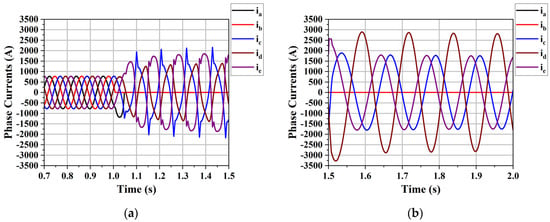
Figure 12.
Stator currents: (a): normal and double-phase open-circuit fault; (b): fault tolerance operation.
Figure 13 shows the electromagnetic torque, rotor speed, and DC-link voltage. As can be seen from the figure, the fluctuations are higher compared to the single-phase fault, mainly due to the strong unbalanced condition occurring inside the machine. The torque ripples under the double-phase fault are worse than those in the single-phase fault, increasing significantly from around 2.73% during normal operation to approximately 163.78%, which represents a critical condition for the electrical machine and the system in general. After applying the fault-tolerant control strategy, the torque ripples decrease to around 4.70%, as shown in the figures below.
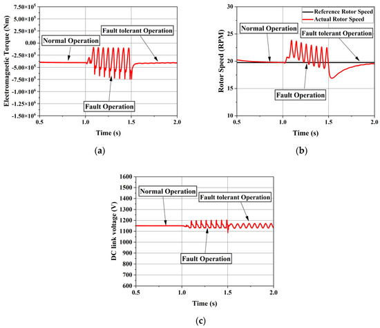
Figure 13.
System variables for double-phase open-circuit fault: (a): electromagnetic torque; (b): Rotor Speed; (c): DC link voltage.
Figure 14 shows the grid current under double-phase fault conditions and fault-tolerant control. As can be seen from the figure, the harmonics and power fluctuations are higher in this case compared to the single-phase fault, primarily due to the unbalanced condition. The harmonics of the grid current under the fault condition increase from 2.94% to 38.08%; however, after applying the fault-tolerant strategy, the harmonics decrease to around 27%.
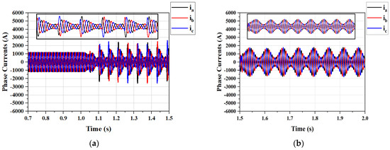
Figure 14.
Grid currents: (a): double-phase open-circuit fault; (b): fault tolerance operation.
4.3. Wind Speed Variation
The wind has an intermittent nature, meaning that its speed is unpredictable, and this is one of the key factors that should be given particular attention when dealing with fault-tolerant strategies. Hence, this section evaluates the system under varying wind speeds to assess the effectiveness of the fault-tolerant strategy under such conditions and summarizes all results for the different cases in the final table of this section. Figure 15 and Figure 16 show the machine currents, torque, and DC-link voltage during single-phase and double-phase faults at different wind speeds, respectively. As shown in the figures, wind speed affects the system’s operation during the application of the fault-tolerant strategy by increasing the fluctuations in all variables, such as torque ripple and DC-link voltage, which in turn increase the harmonics in the grid current. Nevertheless, it is important to note that the increase is relatively minor under a single-phase fault, while it is more significant and severe under a double-phase fault condition. This is mainly due to the high current sustained in phase ‘d’, which imposes considerable stress on the system.
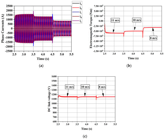
Figure 15.
System variables under fault-tolerant strategy for single-phase open-circuit fault with varying wind speed: (a) Machine currents; (b) Torque; (c) DC link voltage.
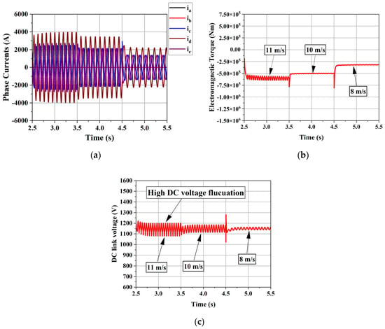
Figure 16.
System variables under fault-tolerant strategy for double-phase open-circuit fault with varying wind speed: (a) Machine currents; (b) Torque; (c) DC link voltage.
Table 3 and Table 4 summarize all data related to total harmonic distortion and torque ripples. The results confirm that the fault-tolerant strategy enhances system performance under fault conditions by reducing torque ripples, DC-link voltage oscillations, and grid current harmonics, particularly in single-phase faults. However, in double-phase faults, the strategy remains effective only at low wind speeds. In contrast, high wind speeds and gusts increase the generator stator currents, potentially posing severe risks. These results highlight the importance of further research to ensure reliable operation under such critical fault scenarios. Future studies may consider the implementation of de-rating factor techniques or the development of advanced pitch-angle control systems to limit current magnitudes and protect the generator, thereby enhancing overall system reliability.

Table 3.
Total harmonic distortion of the grid current (THD %).

Table 4.
Torque ripple percentage under different operation conditions.
5. Conclusions
This paper presented an investigation of a fault-tolerant control strategy for a grid-connected wind energy conversion system (WECS) based on a five-phase PMSG. The proposed strategy was designed to maintain continuous operation and reduce electrical and mechanical fluctuations during single- and double-phase open-circuit faults. Simulation results demonstrated that the method effectively redistributed the phase currents to preserve a constant MMF and stabilize system variables under both fault scenarios. The results can be summarized as follows:
- Under a single-phase open-circuit fault at 9 m/s, the proposed strategy reduced torque fluctuations by decreasing torque ripple from 49% to 3%, thereby enhancing machine performance. Furthermore, the total harmonic distortion (THD) of the grid current decreased from 11.54% to 4.89%, demonstrating an overall improvement in stability and power quality.
- For the double-phase open-circuit fault at 9 m/s, the proposed strategy significantly reduced torque ripple from 163.75% to 4.70% and decreased the THD from 38.08% to 27.06%. However, this case represents one of the most critical scenarios, as the system continued to operate under unbalanced conditions with a high current in phase ‘d’, which explains why the harmonics are higher compared to the single-phase open-circuit case.
- When subjected to a single-phase open-circuit fault at varying wind speeds, the proposed strategy maintained high stability, although the THD of the grid current increased slightly as wind speed increased. When the wind speed rose from 9 m/s to 11 m/s, the THD increased from 4.89% to 5.89%. However, these changes remained within an acceptable range, confirming the effectiveness of the proposed strategy.
- In the case of double-phase open-circuit fault at varying wind speeds, this scenario—previously discussed—is considered critical due to the high current in phase ‘d’. As wind speed increases, the current amplitude increases, and the unbalanced condition becomes more severe. This in turn will lead to inject high harmonics to the grid, which is unacceptable. Furthermore, the currents in this case may exceed their rated limits at high wind speed, causing severe damage to the generator, and this requires either an immediate system shutdown or speed and load adjustments. The speed and the torque of the generator can be controlled by using either the de-rating factor to decrease the values under high wind speed or advanced control strategies to control the pitch angle and limit the output power.
Overall, the results confirm that five-phase PMSGs, combined with appropriate fault-tolerant control, offer a promising solution for enhancing the reliability of wind energy systems. Although the control algorithm relies mainly on algebraic current redistribution and conventional PI controllers, its practical application may still be influenced by non-ideal factors such as measurement noise, sensor delay, and converter dead time. Moreover, under high-wind-speed conditions, the redistributed phase currents may exceed their rated values, potentially increasing thermal stress on the generator. Future research will therefore focus on developing adaptive current-limiting and temperature-aware control algorithms, which could integrate faster fault-detection and isolation logic, and validating the proposed method experimentally through hardware-in-the-loop (HIL) or laboratory-scale prototypes.
Author Contributions
Conceptualization, A.A. and M.A.; methodology, M.A.; software, M.A.; validation, A.A. and M.A.; formal analysis, M.A.; writing—original draft preparation, M.A.; writing—review and editing, M.A. and A.A.; visualization, M.A.; supervision, A.A.; project administration, A.A. All authors have read and agreed to the published version of the manuscript.
Funding
This research was funded by Deanship of Graduate Studies and Scientific Research in Qassim University under the number (QU-J-PG-2-2025-56873).
Institutional Review Board Statement
Not applicable.
Informed Consent Statement
Not applicable.
Data Availability Statement
The original contributions presented in this study are included in the article. Further inquiries can be directed to the corresponding author.
Acknowledgments
The authors gratefully acknowledge Qassim University, represented by the Deanship of Graduate Studies and Scientific Research, for the financial support for this research under the number (QU-J-PG-2-2025-56873) during the academic year 1446 AH/2024 AD.
Conflicts of Interest
The authors declare no conflicts of interest.
References
- Ward, E.; Härer, H. Preliminary investigation of an invertor-fed 5-phase induction motor. Proc. Inst. Electr. Eng. 1969, 116, 980–984. [Google Scholar] [CrossRef]
- Rahman, K.; Rahman, S.; Bhaskar, M.S.; Iqbal, A.; Khandakar, A.; Tariq, M.; Alamri, B. Field-oriented control of five-phase induction motor fed from space vector modulated matrix converter. IEEE Access 2022, 10, 17996–18007. [Google Scholar] [CrossRef]
- Song, Z.; Jia, Y.; Liu, C. Open-phase fault-tolerant control strategy for dual three-phase permanent magnet synchronous machines without controller reconfiguration and fault detection. IEEE Trans. Power Electron. 2022, 38, 789–802. [Google Scholar] [CrossRef]
- Zhou, X.; Li, S.; Lu, M.; Zeng, F.; Zhu, M.; Yu, Y. New fault tolerance method for open-phase PMSM. IEEE Access 2019, 7, 146416–146427. [Google Scholar] [CrossRef]
- Wang, H.; Gu, C.; Buticchi, G.; Zhao, H.; Wang, S. Fault Tolerant Control Method for Double-phase Open-circuit Fault with Current and Voltage Reconfiguration in Five-phase SPMSM. In Proceedings of the 26th International Conference on Electrical Machines and Systems (ICEMS), Zhuhai, China, 5–8 November 2023; IEEE: New York, NY, USA, 2023; pp. 979–983. [Google Scholar]
- Frikha, M.A.; Croonen, J.; Deepak, K.; Benômar, Y.; El Baghdadi, M.; Hegazy, O. Multiphase motors and drive systems for electric vehicle powertrains: State of the art analysis and future trends. Energies 2023, 16, 768. [Google Scholar] [CrossRef]
- Jlassi, I.; Bento, F.; Cardoso, A.J.M. Fault-Tolerant PMSG Direct-Drive Wind Turbines, using Vector Control Techniques with Reduced DC-Link Ratings. In Proceedings of the IECON 2018—44th Annual Conference of the IEEE Industrial Electronics Society, Washington, DC, USA, 21–23 October 2018; IEEE: New York, NY, USA, 2018; pp. 1214–1219. [Google Scholar]
- Jlassi, I.; Cardoso, A.J.M. Fault-tolerant back-to-back converter for direct-drive PMSG wind turbines using direct torque and power control techniques. IEEE Trans. Power Electron. 2019, 34, 11215–11227. [Google Scholar] [CrossRef]
- Freire, N.M.A.; Cardoso, A.J.M. A fault-tolerant direct controlled PMSG drive for wind energy conversion systems. IEEE Trans. Ind. Electron. 2013, 61, 821–834. [Google Scholar] [CrossRef]
- Freire, N.M.A.; Cardoso, A.J.M. A fault-tolerant PMSG drive for wind turbine applications with minimal increase of the hardware requirements. IEEE Trans. Ind. Appl. 2013, 50, 2039–2049. [Google Scholar] [CrossRef]
- Bolbolnia, R.; Heydari, E.; Abbaszadeh, K. Fault tolerant control in direct-drive PMSG wind turbine systems under open-circuit faults. In Proceedings of the 2020 11th Power Electronics, Drive Systems, and Technologies Conference (PEDSTC), Tehran, Iran, 4–6 February 2020; IEEE: New York, NY, USA, 2020; pp. 1–5. [Google Scholar]
- Peng, X.; Liu, Z.; Jiang, D. A review of multiphase energy conversion in wind power generation. Renew. Sustain. Energy Rev. 2021, 147, 111172. [Google Scholar] [CrossRef]
- Pantea, A.; Yazidi, A.; Betin, F.; Carriere, S.; Sivert, A.; Vacossin, B.; Henao, H.; Capolino, G.-A. Fault-tolerant control of a low-speed six-phase induction generator for wind turbines. IEEE Trans. Ind. Appl. 2018, 55, 426–436. [Google Scholar] [CrossRef]
- Pantea, A.; Yazidi, A.; Betin, F.; Carriere, S.; Sivert, A.; Capolino, G.-A. Fault tolerant control of six-phase induction generator for wind turbines. In Proceedings of the 2017 IEEE International Electric Machines and Drives Conference (IEMDC), Miami, FL, USA, 21–24 May 2017; IEEE: New York, NY, USA, 2017; pp. 1–7. [Google Scholar]
- Toledo, S.; Caballero, D.; Maqueda, E.; Arrua, S.; Gomez-Redondo, M.; Gregor, R.; Rivera, M.; Wheeler, P. Fault tolerant predictive control for six-phase wind generation systems using multi-modular matrix converter. In Proceedings of the IECON 2021—47th Annual Conference of the IEEE Industrial Electronics Society, Toronto, ON, Canada, 13–16 October 2021; IEEE: New York, NY, USA, 2021; pp. 1–6. [Google Scholar]
- Gonzalez, I.; Duran, M.J.; Che, H.S.; Levi, E.; Aguado, J. Fault-tolerant efficient control of six-phase induction generators in wind energy conversion systems with series-parallel machine-side converters. In Proceedings of the 7th IET International Conference on Power Electronics, Machines and Drives (PEMD 2014), Manchester, UK, 8–10 April 2014; IET: Stevenage, UK, 2014; pp. 2–10. [Google Scholar]
- Gonzalez-Prieto, I.; Duran, M.J.; Che, H.S.; Levi, E.; Bermúdez, M.; Barrero, F. Fault-tolerant operation of six-phase energy conversion systems with parallel machine-side converters. IEEE Trans. Power Electron. 2015, 31, 3068–3079. [Google Scholar] [CrossRef]
- Zhou, S.; Rong, F.; Yin, Z.; Huang, S.; Zhou, Y. HVDC transmission technology of wind power system with multi-phase PMSG. Energies 2018, 11, 3294. [Google Scholar] [CrossRef]
- Seck, A.; Moreau, L.; Benkhoris, M.-F.; Machmoum, M. Automatic generation of optimal phase currents for five-phase PMSG control under open phase condition. In Proceedings of the IECON 2017—43rd Annual Conference of the IEEE Industrial Electronics Society, Beijing, China, 29 October–1 November 2017; IEEE: New York, NY, USA, 2017; pp. 3847–3852. [Google Scholar]
- Pham, H.-T.; Bourgeot, J.-M.; Benbouzid, M. Fault-tolerant model predictive control of 5-phase PMSG under an open-circuit phase fault condition for marine current applications. In Proceedings of the IECON 2016—42nd Annual Conference of the IEEE Industrial Electronics Society, Florence, Italy, 23–26 October 2016; IEEE: New York, NY, USA, 2016; pp. 5760–5765. [Google Scholar]
- Zhao, J.; Xie, W. Fault-Tolerant Control Strategy of Five-Phase Permanent Magnet Synchronous Generator. In Proceedings of the 6th International Conference on Electrical Engineering and Green Energy (CEEGE), Grimstad, Norway, 6–9 June 2023; IEEE: New York, NY, USA, 2023; pp. 119–123. [Google Scholar]
- Stanescu, D.; Digulescu, A.; Ioana, C.; Candel, I. Early-warning indicators of power cable weaknesses for offshore wind farms. In Proceedings of the OCEANS 2023—MTS/IEEE US Gulf Coast, Biloxi, MS, USA, 25–28 September 2023; IEEE: New York, NY, USA, 2023; pp. 1–6. [Google Scholar]
- Nandipati, S.; Nichenametla, A.N.; Waghmare, A.L. Cost-effective maintenance plan for multiple defect types in wind turbine blades. In Proceedings of the 2018 Annual Reliability and Maintainability Symposium (RAMS), Reno, NV, USA, 22–25 January 2018; IEEE: New York, NY, USA, 2018; pp. 1–5. [Google Scholar]
- Hosseini, S.A.; Ahmedi, A.; Blaabjerg, F.; Peyghami, S. Exploring wind farm reliability: Key concepts, databases and fault Trees. Renew. Sustain. Energy Rev. 2025, 211, 115227. [Google Scholar] [CrossRef]
- Yang, C.; Jia, J.; He, K.; Xue, L.; Jiang, C.; Liu, S.; Zhao, B.; Wu, M.; Cui, H. Comprehensive analysis and evaluation of the operation and maintenance of offshore wind power systems: A survey. Energies 2023, 16, 5562. [Google Scholar] [CrossRef]
- Ali, W.; El-Thalji, I.; Giljarhus, K.E.T.; Delimitis, A. Classification analytics for wind turbine blade faults: Integrated signal analysis and machine learning approach. Energies 2024, 17, 5856. [Google Scholar] [CrossRef]
- Hes, J.B.; Jiang, X. Predictive maintenance scheduling framework for offshore wind turbines based on condition monitoring: A review. In Advances in Maritime Technology and Engineering; CRC Press: Boca Raton, FL, USA, 2024; pp. 563–574. [Google Scholar]
- Majout, B.; Bossoufi, B.; Bouderbala, M.; Masud, M.; Al-Amri, J.F.; Taoussi, M.; El Mahfoud, M.; Motahhir, S.; Karim, M. Improvement of PMSG-based wind energy conversion system using developed sliding mode control. Energies 2022, 15, 1625. [Google Scholar] [CrossRef]
- da Silva, L.T.F.; Tomim, M.A.; Barbosa, P.G.; de Almeida, P.M.; da Silva Dias, R.F. Modeling and simulating wind energy generation systems by means of co-simulation techniques. Energies 2023, 16, 7013. [Google Scholar] [CrossRef]
- Slootweg, J.G.; Polinder, H.; Kling, W.L. Representing wind turbine electrical generating systems in fundamental frequency simulations. IEEE Trans. Energy Convers. 2003, 18, 516–524. [Google Scholar] [CrossRef]
- Zeghlache, A.; Mekki, H.; Benkhoris, M.F.; Djerioui, A.; Ziane, D.; Zeghlache, S. Robust Fault-Tolerant Control of a Five-Phase Permanent Magnet Synchronous Motor under an Open-Circuit Fault. Appl. Sci. 2024, 14, 5190. [Google Scholar] [CrossRef]
- Parsa, L.; Toliyat, H.A. Fault-tolerant interior-permanent-magnet machines for hybrid electric vehicle applications. IEEE Trans. Veh. Technol. 2007, 56, 1546–1552. [Google Scholar] [CrossRef]
- Mousa, H.H.; Youssef, A.R.; Mohamed, E.E. Model predictive speed control of five-phase PMSG based variable speed wind generation system. In Proceedings of the 2018 Twentieth International Middle East Power Systems Conference (MEPCON), Cairo, Egypt, 18–20 December 2018; IEEE: New York, NY, USA, 2018; pp. 304–309. [Google Scholar]
- Parsa, L.; Toliyat, H.A. Fault-tolerant five-phase permanent magnet motor drives. In Proceedings of the Conference Record of the 2004 IEEE Industry Applications Conference, 2004, 39th IAS Annual Meeting, Seattle, WA, USA, 3–7 October 2004; IEEE: New York, NY, USA, 2004; Volume 2, pp. 1048–1054. [Google Scholar]
- Ding, S.; Chen, W.; Tong, M.; Xie, F.; Zheng, C. Fault tolerant control for a five-phase permanent magnet synchronous machine driving system. In Proceedings of the 2016 IEEE 11th Conference on Industrial Electronics and Applications (ICIEA), Hefei, China, 5–7 June 2016; IEEE: New York, NY, USA, 2016; pp. 2021–2025. [Google Scholar]
- Huang, N. Simulation of Power Control of a Wind Turbine Permanent Magnet Synchronous Generator System. Master’s Thesis, Marquette University, Milwaukee, WI, USA, 2013. [Google Scholar]
Disclaimer/Publisher’s Note: The statements, opinions and data contained in all publications are solely those of the individual author(s) and contributor(s) and not of MDPI and/or the editor(s). MDPI and/or the editor(s) disclaim responsibility for any injury to people or property resulting from any ideas, methods, instructions or products referred to in the content. |
© 2025 by the authors. Licensee MDPI, Basel, Switzerland. This article is an open access article distributed under the terms and conditions of the Creative Commons Attribution (CC BY) license (https://creativecommons.org/licenses/by/4.0/).