1. Introduction
As intelligent manufacturing becomes more digitalized, large amounts of data are generated, including dynamic and static data from sensors installed on devices/equipment. These data, together with process (control) data from devices/equipment, quality data from Manufacturing Execution System (MES), and capability data for production equipment and workers at the stations of production lines, form aligned data tables at the Ends (for devices), Edges (for production lines), and Cloud (for central control platform). These aligned data can be used to train AI models to generate control parameter values for optimizing the production process and for health management of top-level applications. Consequently, the efficiency of the equipment is increased and the cost of materials is reduced. The whole process is called intelligent manufacturing.
Obviously, the kernel of intelligent manufacturing is the effective utilization of data. To achieve this, we should have a way to store and display the massive data such that it can be quickly queried to support all kinds of computations. However, it is not easy due to the following challenges. (1) Intelligent manufacturing systems generate massive volumes of time-series data due to high-frequency sensor sampling (often at millisecond or sub-millisecond intervals) across numerous production devices. This creates significant challenges for storage scalability and query performance, as traditional database systems struggle with the write-intensive workloads and complex temporal analytics required for real-time process optimization. The storage costs and query latencies associated with such massive datasets often become prohibitive for maintaining responsive manufacturing operations. (2) The heterogeneous nature of production equipment introduces significant data integration complexity, as different devices employ varying communication protocols (e.g., OPC-UA, Modbus, MQTT, proprietary protocols) and generate structurally diverse data types, including structured sensor readings, semi-structured log files, and unstructured maintenance records. This heterogeneity requires flexible data storage architectures capable of schema evolution and multi-modal data management without compromising query performance or data consistency. (3) Flexible production represents one of the fundamental characteristics of intelligent manufacturing systems. This flexibility encompasses the ability to efficiently adapt to product diversity, volume variations, and changing production requirements through multiple mechanisms, including equipment reconfiguration, process parameter adjustment, and dynamic resource allocation. To enable such flexibility, the underlying data storage and management systems must support heterogeneous data integration from diverse production processes, real-time query processing for dynamic decision-making, and concurrent access patterns arising from simultaneous multi-product manufacturing scenarios.
However, current manufacturing data storage architectures exhibit significant limitations in multiple critical areas. Architecturally, existing approaches typically rely on system-specific customizations and siloed storage solutions tailored to particular production scenarios or equipment types, leading to limited interoperability, duplicated infrastructure costs, and reduced scalability when expanding to new production lines or integrating additional equipment types. Functionally, these systems struggle to maintain temporal data consistency across parallel production streams, to support scalable real-time analytics for process optimization, and to accommodate varying product data requirements. Furthermore, such fragmented and customized solutions fundamentally hinder the development of unified analytics platforms capable of providing holistic insights across diverse manufacturing operations, thereby limiting the realization of truly intelligent manufacturing systems.
This paper proposes a metamodel-driven hierarchical and topological data representation to mitigate the aforementioned challenges in intelligent manufacturing data storage and management.
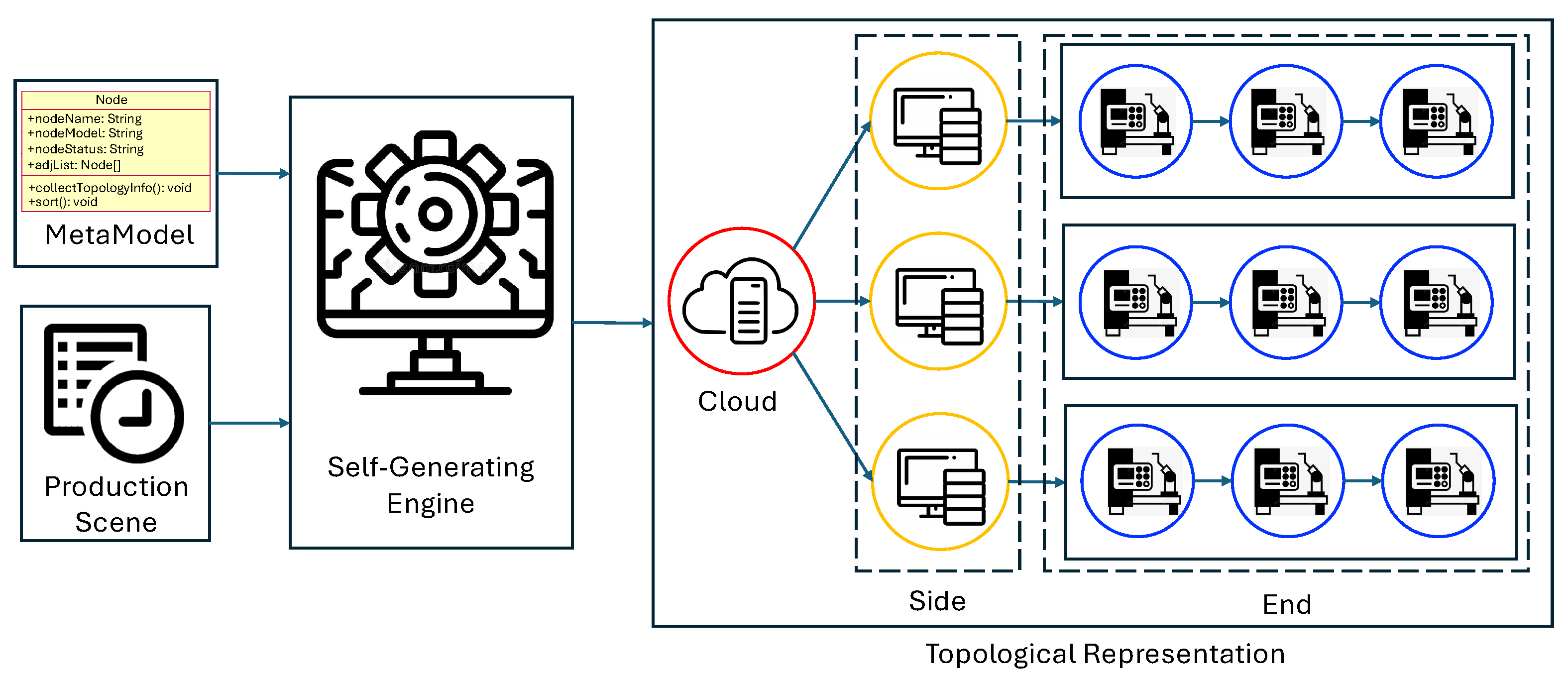
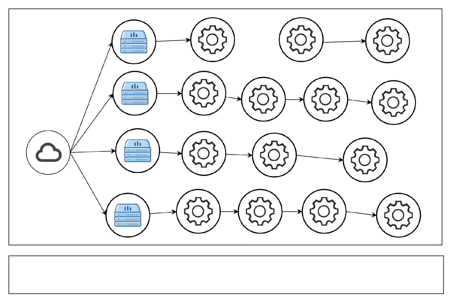
Figure 1 shows the general framework of our method. First, to deal with the first challenge, we design a three-layer hierarchical architecture, i.e., cloud layer, edge layer, and end layer, to store different data into different layers, therefore improving data storage and query. Second, to deal with the second challenge, we design metamodels for the cloud, edge, and end nodes. Metamodeling theory originates from software engineering and is widely applied in computer and information sciences. Conceptually, metamodeling operates at a higher level of abstraction than standard modeling processes [
1]. In this work, we apply metamodeling theory to define unified metamodels to describe different devices, resulting in an end metamodel, an edge metamodel, and a cloud metamodel. The end metamodel describes the equipment, sensors, and/or robots, the edge metamodel is used to describe production lines, and the cloud metamodel is for the central control platform. Consequently, each specific manufacturing scenario is realized through metamodel instantiation automatically using the corresponding production scene data without custom development. The instantiated models contain all the required data that can be used to support AI model training and provide services for the applications in the future. Third, building upon the hierarchical metamodel structure, we propose a graph-based topological representation that captures the structural relationships within manufacturing scenes. This topological model abstracts the connections between manufacturing entities (equipment, sensors, production lines).
The key advantages of this topological approach are its support for dynamic manufacturing reconfiguration and fast data querying for local computing. On one hand, when production lines undergo changes, only the topology metadata requires updates while the underlying metamodel-based data storage architecture remains unchanged. On the other hand, with the topological representation, data queries in intelligent manufacturing systems can be classified into three categories based on their temporal and spatial scope: local sensor queries at end nodes, production line queries at edge nodes, and cross-line analytical queries at cloud nodes. This hierarchical query structure enables fast data retrieval.
Our method has advantages in the following aspects:
It provides a universal framework to describe topological representation of all kinds of production scenes, such that the description of a specific production scene is an instantiation of the metamodel by the collected data.
It provides automatic instantiation of metamodels to generate concrete data models (represented in UML in this work) from production data, rather than directly generating new data representation models or tuning existing ones, which is often infeasible for most companies due to ever-growing parameter sizes, vast data requirements, and soaring computational costs.
It can store data at the cloud (control platform), edge (production line), and end (device) such that it provides fast data querying and supports local computing, such as local optimization, and automatically display their physical topology.
We have implemented our model manually and demonstrated the benefits via experiments. It is worth noting that this work mainly focuses on the design of metamodels and the automatic instantiation process, while the detailed design of database optimization strategies, protocol adapter implementations, and language-specific code generation templates is beyond the scope of this work. However, based on the generated models, different implementation approaches and tools [
2,
3,
4] can be applied to generate language-specific code. This work forms the bottom layer of a generated operating system for intelligent manufacturing, providing services to the upper control layer to construct a database.
The rest of this paper is organized as follows.
Section 2 gives a brief literature review.
Section 3 gives our metamodel definitions for cloud, edge, and end nodes, and the instantiation of the metamodels.
Section 4 establishes correctness properties of the proposed metamodel-based topological representation.
Section 5 gives the experimental results. Finally,
Section 6 concludes this work and proposes future work.
2. Related Work
Data representation serves as the fundamental layer enabling intelligent manufacturing systems to process, analyze, and act upon the vast quantities of information generated in modern production environments. The transition from traditional manufacturing to Industry 4.0 paradigms has necessitated sophisticated approaches to structuring, encoding, and presenting manufacturing data to support autonomous decision-making, predictive analytics, and real-time optimization.
Ontology-Based Representations (Ontology). Recent research has demonstrated the effectiveness of ontology and proposed several ontological frameworks for manufacturing data representation [
5,
6,
7,
8,
9,
10,
11,
12,
13,
14,
15,
16]. In [
5], the authors discussed the usefulness of ontologies for data formalization and sharing in a manufacturing environment and proposed an ontology architecture for manufacturing, i.e., MASON (MAnufacturing’s Semantics ONtology). It contains three concepts: entities, which provide concepts to specify the product, operations, which describe the processes linked to manufacturing, and resources, which identify the set of resources required for manufacturing. Similarly, the authors in [
6] discussed the important role of ontology, which can provide semantically abundant vocabularies and metadata for expressing and discovering information, and then proposed a manufacturing ontology framework that defines five ontologies: base, device, process, parameter, and product ontologies. With these ontologies, the framework can describe the entire production process from order to products. Even though ontology-based methods provide useful methods to describe the data in manufacturing systems, they cannot be directly used for real-time data storage and AI model training.
Knowledge Graphs (KGs). Manufacturing knowledge graphs have emerged as powerful tools for fusing complex information and enabling cognitive manufacturing decision-making in manufacturing systems, therefore making production lines more efficient and flexible with higher quality output [
17,
18,
19,
20,
21,
22,
23]. Peroni et al. [
18] developed a knowledge graph solution for Imperial Fashion, a major Italian fast-fashion company, to efficiently manage and enrich continuously collected data. The approach integrates diverse information sources—including product and sales data—to support data visualization and predictive sales analysis. The work in [
24] proposed a knowledge graph to represent a digital twin of a production line. It integrates contextual data (such as equipment configuration) with operational data (such as process data and events). The goal is to provide automated recommendations for integrating unknown entities into the existing structure of the knowledge graph, keeping the digital twin in sync without manual modeling effort. In [
22], the authors proposed a knowledge graph-based data representation approach for Industrial Internet of Things-enabled cognitive manufacturing. Based on the digital thread of manufacturing process data, a multi-layer manufacturing knowledge graph is established, including device sensing data, production processing data, and business processing data. With the established knowledge graph, a cognition-driven approach is proposed with a perception-cognition dual system, which achieves perception analysis and cognition decision-making in the resource allocation of the manufacturing process. The work [
23] proposed a knowledge graph-based operational data representation method for the digital twin shop-floor. The approach models entities and relationships to provide semantic integration of production line and process information. By comprehensively analyzing and managing operational data from various information systems, it establishes a unified, quantified, formal, and logical framework for operational data representation. This multi-dimensional structure encompasses manufacturing resource, process, task, and execution information.
High-Resolution Time Series Data Representation (TS Data). Due to the emergence of intelligent manufacturing technologies, manufacturing processes generate continuous streams of sensor data requiring specialized temporal representations. High-resolution time-series data is ubiquitous in industrial settings, enabling affordable and robust sensor systems for data acquisition [
25,
26]. A high-resolution time series is a time series with a large number of measurements over a large number of time [
26], which is also called a high-frequency time series, long time series, or long sequence [
27]. The authors in [
28] Avik Ghosh proposed an adaptive time-warping to deal with the high-frequency industrial time-series data, enabling real-time pattern recognition and decision-making in smart manufacturing environments [
29] and then designed a suite of novel techniques for data management in MES, including Adaptive Multi-Resolution Storage, Context-Aware Compression, Hierarchical Bitmap Indexing, Streaming Analytics Pipeline, Adaptive Process Control Integration, and Distributed Edge Compression and Edge-Assisted Query Processing [
28].
Event-based Data Representations (Event). Event-based data representations focus on transforming low-level data into useful high-level information/states, reducing data volume while preserving critical process information and supporting intelligent decision-making [
30,
31,
32]. For example, in [
30], the authors proposed an event- and service-based information system architecture for rapid integration of smart services into existing factory infrastructure. Therefore, simple messages from all kinds of devices can be sent and transformed into high-level knowledge used by smart services for online monitoring, control, optimization, and reconfiguration. Ringsquandl et al. [
31] proposed an event-based knowledge graph to represent and share industrial knowledge, which encompasses both master and operational data. To complete the knowledge graph, operational data, especially events, such as alarm codes or operator information messages, from different locations are collected and later aggregated in log files. Observing these events enables the digital twin to track some of the activity carried out by the physical equipment.
Metamodel-Driven Data Representation (Metamodel). Production data modeling and model design have emerged as promising areas in intelligent manufacturing [
33,
34,
35,
36,
37]. In [
35], the authors proposed a product-centric metamodel for production data to be employed for automated predictive quality methods, which contains 16 classes, linked mainly through associations. For increasing the data comprehensibility and reducing the complexity of the model, the authors [
36] proposed an adapted product-centred metamodel for production data as well as a guide to applying the model to an additive manufacturing process.
Different data representation approaches exhibit varying performance characteristics for common manufacturing queries. They typically require customization to deal with flexible manufacturing scenarios and are hard to directly support AI model training for the main functionalities in intelligent manufacturing, including failure prediction, quality prediction, and control parameter optimization. There is a lack of unified methods for modeling data across different devices in intelligent manufacturing, including cloud, edge, and end devices. Moreover, while ontology-based approaches provide semantic richness and knowledge graphs enable complex reasoning, they incur high computational costs, making them unsuitable for real-time manufacturing queries. Time-series databases optimize recent data access but lack semantic context and local compute capabilities. Event-based systems support streaming but require extensive aggregation for historical analysis. Current metamodel-driven methods are product-centric and lack flexible production. In this paper, we design unified metamodels that enable consistent data modeling across these heterogeneous devices. Using these metamodels, we can generate both device-specific data models and topological data representation for the entire production system through a standardized instantiation process. It can achieve low-latency hierarchical storage via cloud–edge–end distribution, and template-driven instantiation enabling scenario-agnostic deployment.
Table 1 compares our proposed method with existing data representation models.
It is important to note that our method for topological architecture construction is specific to the intelligent manufacturing domain, rather than addressing the general problem of efficient graph construction, such as GraphService [
38]. Our proposed topological architecture distinguishes itself through two key characteristics: (1) Semantic structure: The topological architecture comprises nodes with manufacturing-specific attributes, such as abilities, data fields, and domain operations, rather than generic graph structures. (2) Automatic instantiation: Given the metamodel definitions, the topological architecture is generated automatically from MES/SCADA data without manual graph construction. Nevertheless, graph partitioning strategies from systems like GraphService [
38] could inform future optimizations for our topological architecture.
3. Metamodels for Production Scenes
A metamodel is formally defined as an abstract model that describes the structure, syntax, semantics, and constraints of a set of models. It acts as a model of models, specifying the permissible elements, relationships, and rules that a model must follow.
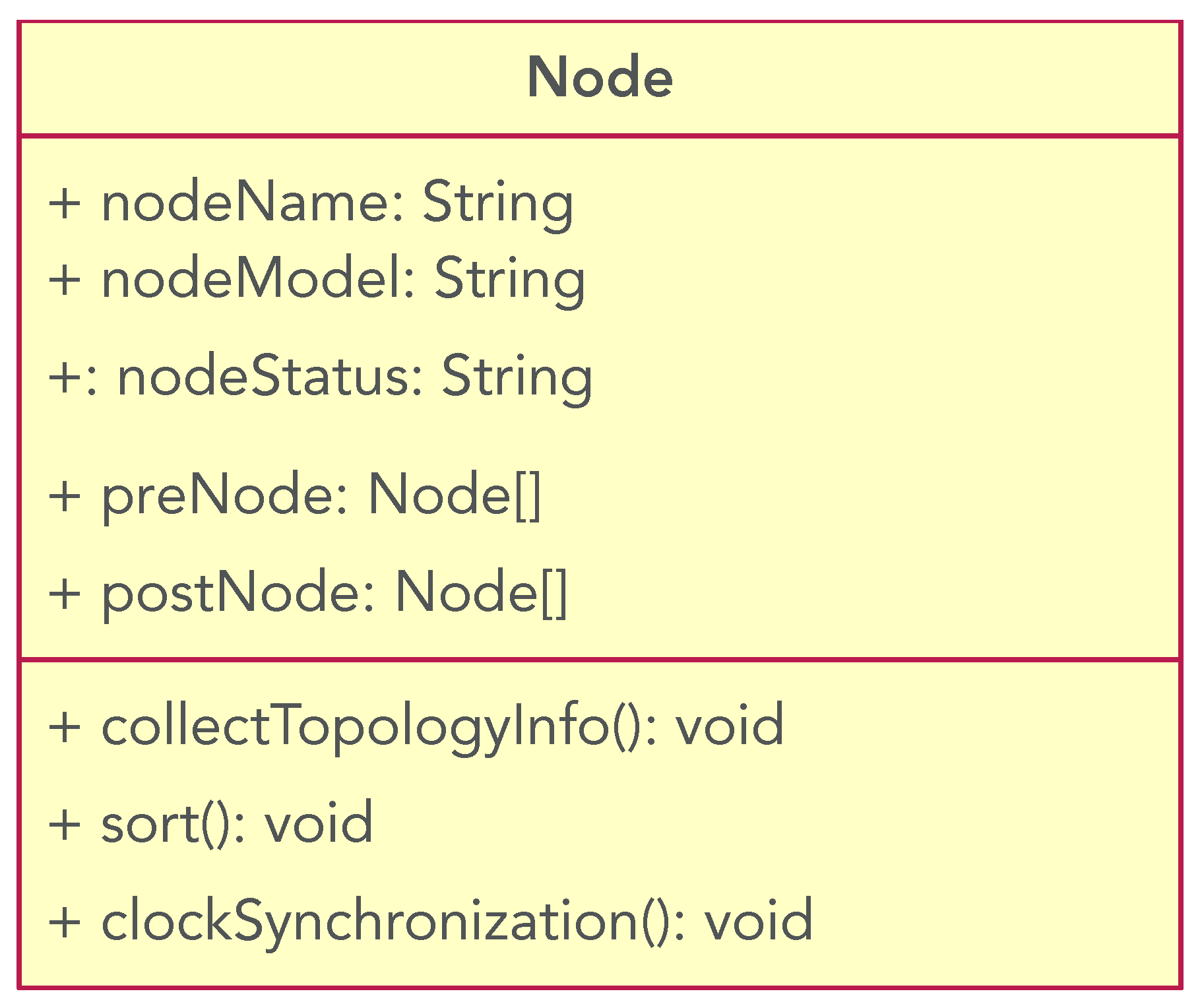
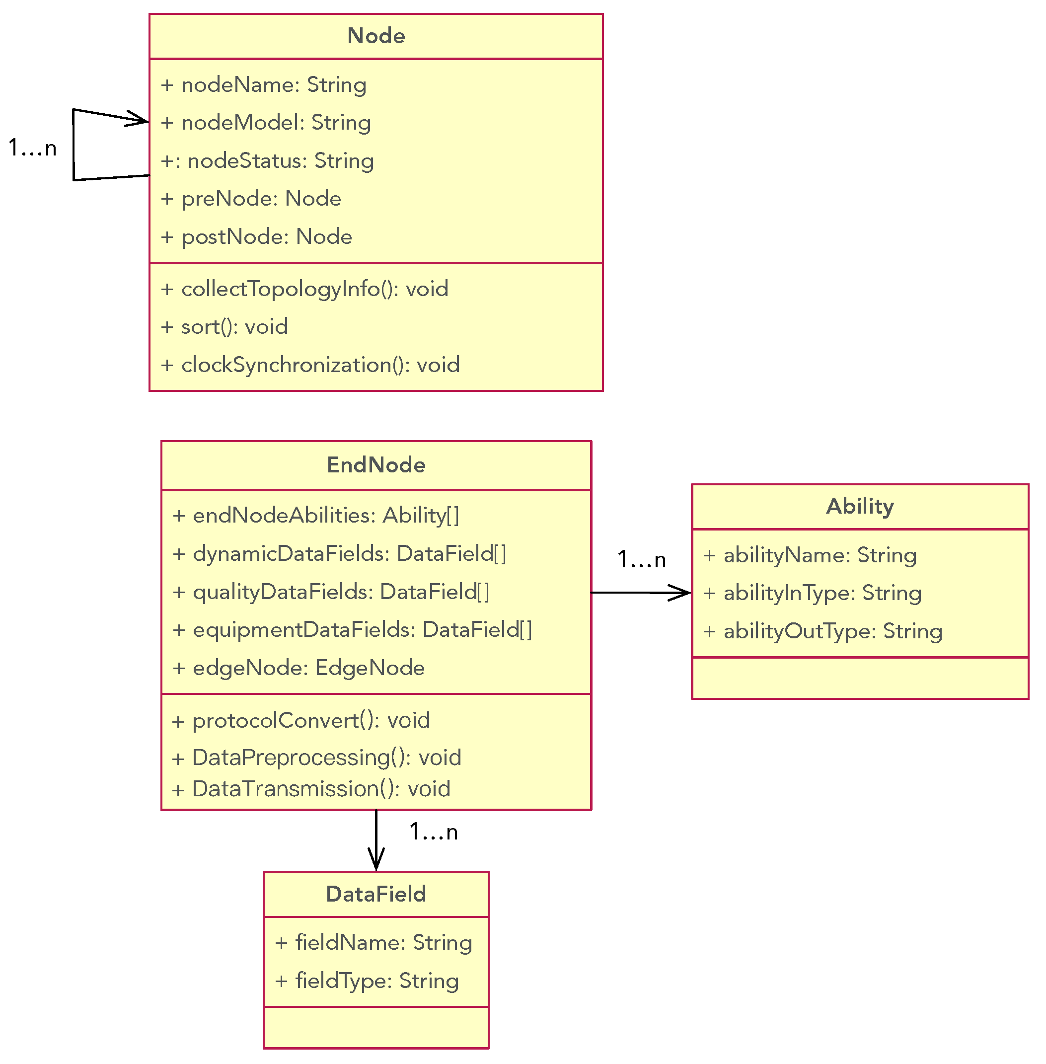
Before presenting the metamodels for cloud, edge, and end, we first introduce the basic metamodel, called Node metamodel, for cloud-edge-cloud manufacturing systems. Each cloud, edge, and end is an inheritance of the node and can be regarded as a node. Each node has a unique name and a type that identifies the kind of node (i.e., cloud, edge, or end), the status of the node, and its preceding and succeeding nodes in the production system. As different nodes have different time measures, each node needs a function for time alignment. Moreover, each node should have the function to construct the topological data representation stored in it. Therefore, a Node metamodel can be described as follows.
Definition 1. A Node Metamodel is a model to describe the building of a node model. It contains the following attributes and functions.
nodeName: It is the name attribute of a node. Each node should specify a unique node name.
nodeType: It describes the type of equipment at the node.
nodeStatus: This is an enumerated value, and its value is related to the business scenario, such as the processing status of terminal equipment, the online status of edge equipment, etc.
preNode: It describes the set of preceding nodes of a node.
postNode: It describes the set of succeeding nodes of a node.
clockSynchronization(): It is a function describing the clock synchronization operation of this node.
collectTopologyInfo(): It is a function describing the operation to retrieve data that will be used to characterize the node.
sort(): The way to construct topological data representation with connected nodes.
Figure 2 describes the node metamodel using UML diagram. We chose UML to describe our metamodels for two key reasons: (1) UML class diagrams provide sufficient expressiveness for our metamodel structure, capturing data attributes, relationships, and operations; and (2) UML has broader tool support and familiarity among software developers who will implement these models.
3.1. Meta-Model for End Devices
A production line includes a set of workstations, each equipped with various machinery, such as equipment, robots, sensors, handheld devices, and so on. These devices generate a large volume of data during the production process. Transmitting the data to the cloud node can consume significant bandwidth and computing resources, potentially disrupting normal production operations. To mitigate this, in our cloud–edge–end architecture, we add an end node for each workstation. It is responsible for local data collection, data preprocessing (e.g., data filtering, data cleaning, and protocol conversion), and data transmission.
In detail, an end node collects data from equipment and sensors and stores data in the corresponding edge node after local preprocessing. The data includes: dynamic data, which describes the states of equipment during the production process; quality data, which describes the quality of the productions; and equipment data, which is the set of configurable parameters of the equipment that affect the production quality and efficiency. To describe these data, we first need to record the name and the type. Since the communication protocols for the devices are very complex, and different devices adopt different protocols, we are not able to use end node and cloud node to accommodate all the protocols in the end node and cloud node. To solve this problem, we define an operation for protocol transformation, which can isolate the differences of the protocols, encapsulate the data, and upload them to the upper layer. In practice, this will be implemented through a registry-based adapter system. For each new protocol, a corresponding adapter must be implemented and registered with the system. During instantiation, when a specific protocol is specified in the MES or SCADA system configuration, our model dynamically invokes the appropriate adapter to perform the required protocol transformation.
According to the functionality of end nodes, we can summarize two basic classes for end nodes: Ability and DataField. An Ability class is associated with the corresponding equipment, describing the equipment’s functionalities. An end node may contain multiple instances of Ability, such as processing-related abilities and data-related abilities. Each ability determines specific operations, such as reading, writing, and sending data. Each ability has its own inputs and outputs. DataField describes the data types and features that can be generated by the equipment. It is one of the most important elements in intelligent manufacturing. Therefore, before giving the definition of the end metamodel, we have the following definitions.
Definition 2. An Ability of an end node can be formally defined as a triple (abilityName, abilityInType, abilityOutType), where
abilityName: The name of the ability related to the end node. It describes the functionalities of the corresponding equipment.
abilityInType: The input type of the ability, i.e., the input type of the equipment. If the device is a process equipment, then the value of the field could be: raw material, or semi-finished product. If the device is data-collecting equipment, then the value of the field could be data or a remote process call.
abilityOutType: The output type of the ability, i.e., the output type of the equipment. If the device is a process equipment, then the value of the field could be: raw material, semi-finished product, or finished product. If the device is data-collecting equipment, then the value of the field could be data or a remote process call.
Definition 3. DataField identifies the data that can be collected from the equipment, which can be defined as a tuple consisting of fieldName and fieldType:
filedName: An identifier of the data. It directly corresponds to the type of information captured by the data, such as temperature and vibration.
fieldType: The data types, such as int, float, and string.
Given the definition of Ability and DataField, we have the following definition of the end metamodel.
Definition 4. The End Metamodel is an abstract description of the end equipment. It can be defined as a tuple (endNodeAbilities, dynamicDataFields, qualityDataFields, equipmentDataFields, edgeNode), where
endNodeAbilities: An Ability array. Through this attribute, we can obtain all possible operations of the end node.
dynamicDataFields: A DataField array. It is used to describe the dynamic data generated by the end equipment during the processing, such as temperature and vibration.
qualityDataFields: A DataField array. It contains different quality data to describe the quality of the output product of the equipment.
equipmentDataFields: A DataField array. It describes the configurable/controllable parameters of the equipment, such as the feed speed of the CNC main shaft. These parameters affect the quality of the products and the performance of the production lines.
upstreamNode: It describes a node with which the end node can communicate directly, either an edge node or a cloud node. This means the end node can only send data to or receive data from its upstream node.
With the end metamodel, we can not only describe all the data fields, but also the abilities and ability constraints.
Figure 3 displays the end metamodel with a UML diagram.
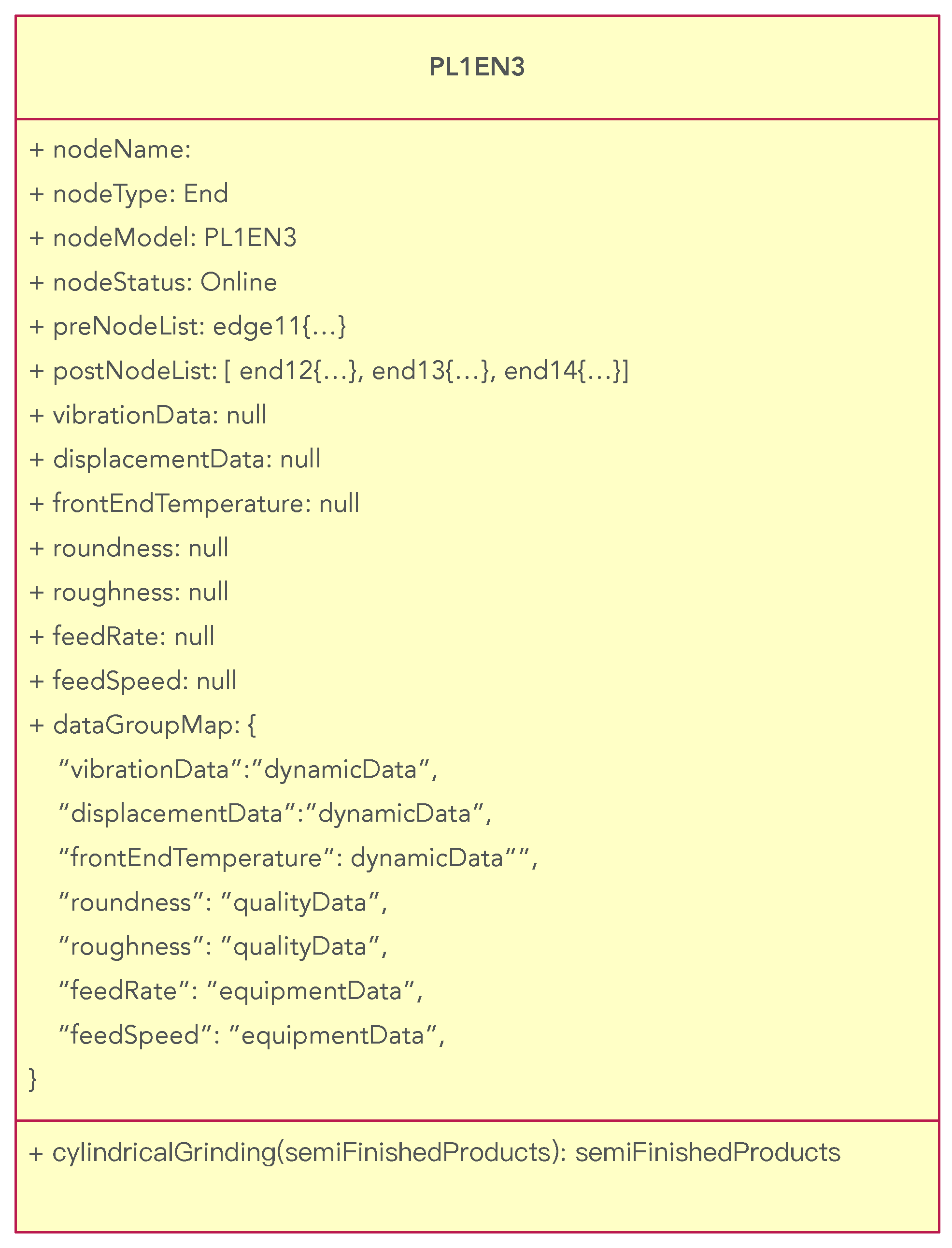
The following is an example of an end node model configured for a computer numerical control (CNC) grinder. In this model, only a subset of the data is provided, and it is described in JSON format. The grinding process is controlled through pre-programmed computer instructions. We assume that the grinder uses the Siemens SINUMERIK 828D numerical control system to manage a bearing production line.
Listing 1 shows the instances of the basic attributes of the end node. The metadata indicates that the name of the end node is “PL1EN3”, and the equipment at the node is “SINUMERIK 828D”. It is currently being processed.
| Listing 1. The instance of the node metamodel in the end node. |
![Applsci 15 11735 i001 Applsci 15 11735 i001]() |
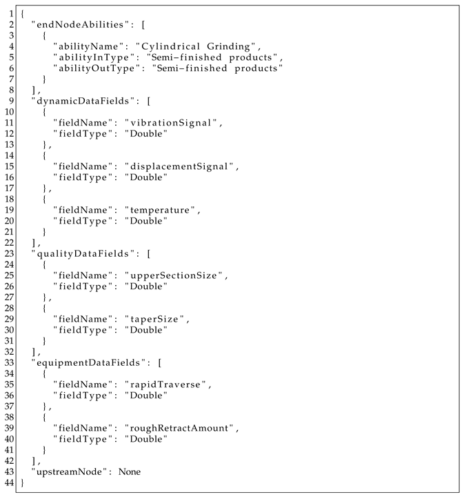
Listing 2 shows the values of other fields in the end model. The metadata for “endeNodeAbilities” indicates that the device PL1EN3 has the ability of cylindrical grinding. It takes a semi-product as input and produces a semi-product for the next process section. The dynamic data during the production process includes vibration signal, displacement signal, and temperature. The quality data contains upper section size and taper size, and the controllable variables of the device are rapid traverse and rough retract amount.
| Listing 2. The instances of other attributes in the end metamodel. |
![Applsci 15 11735 i002 Applsci 15 11735 i002]() |
3.2. Meta-Model for Edge Device
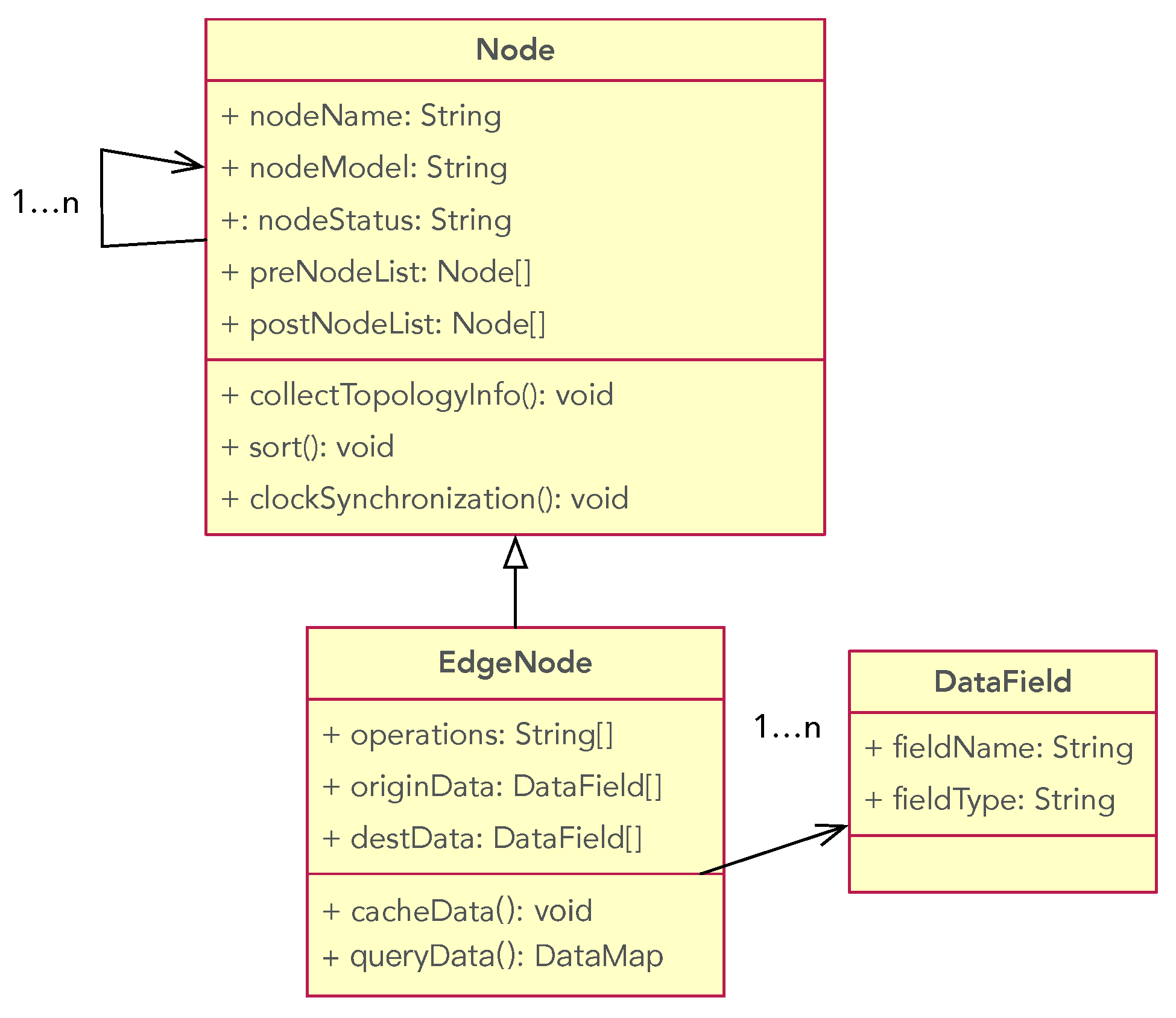
An edge node is located between the ends and the cloud. Edge nodes are usually used to process and analyze data that is sensitive to time delay, extract useful information, and reduce dependence on the cloud. At the same time, the edge node has the capability for data caching and storage, reducing the time delay for data transmission and consumption of bandwidth. Note that real-time data storing and querying are completed at the ends, while the edge node only maintains part of the data for processing and uploading. In summary, an edge node (1) receives the real-time original data from its end node, (2) processes the original data to extract useful information and features using the defined operations, (3) stores the processed feature data for further applications, and (4) sends data to the cloud via data querying. Therefore, we have the following metamodel of the edge nodes.
Definition 5. The metamodel of edge nodes is a tuple of , , , , , where
originData: A DataField list. It represents the raw data uploaded from the end node.
destData: A DataField list. It is a list of features abstracted from the raw data.
operations: It is a set of operations that will be used to abstract the feature values from the raw data. Note that each operation is realized via service invoking.
cacheData(): The method to store data.
queryData(): The method to query data.
Figure 4 displays the edge metamodel with a UML diagram.
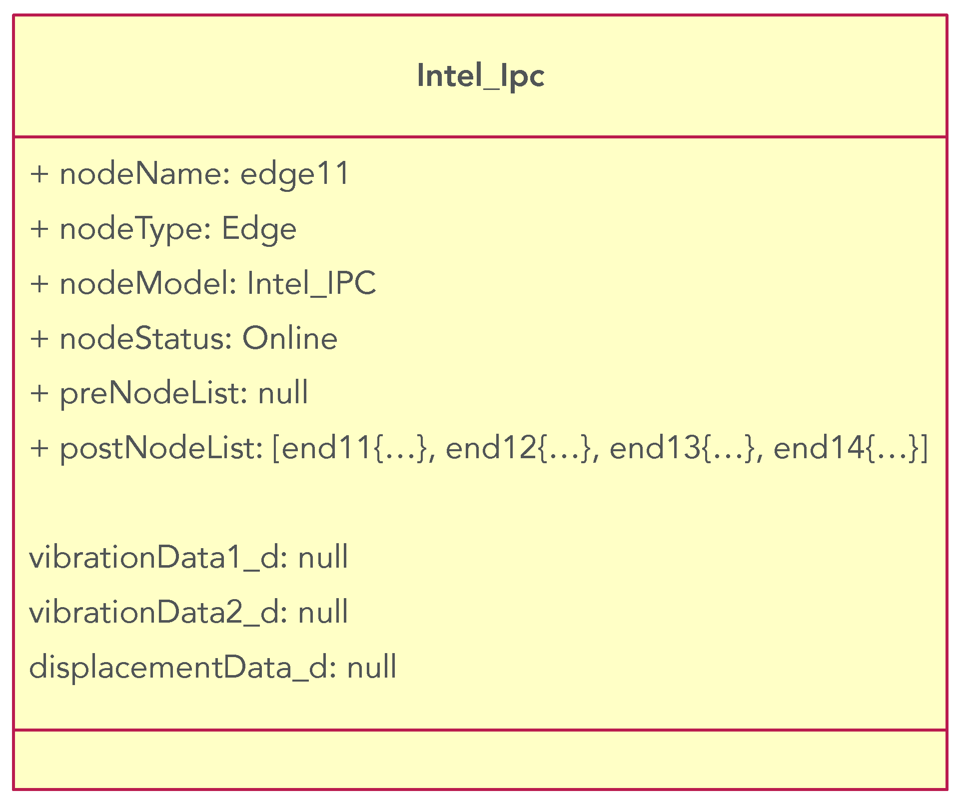
For example, an edge server provides services of data storage, preprocessing of vibration data, down-sampling, and extraction of statistical characteristic values. The general attributes for this node are given in Listing 3. This metadata describes an edge server node with type: CX-5104U, system number: Line1IPC, and its state is: online.
| Listing 3. The instance of node attributes in the edge metamodel. |
![Applsci 15 11735 i003 Applsci 15 11735 i003]() |
Listing 4 gives the field attributes. This data describes the supported services, such as data storing, vibration data analysis, and data down-sampling. Since the data type in the edge node is asynchronous to the end nodes, we do not need to repeat declaring the data fields.
| Listing 4. The instance of other attributes in the end metamodel. |
![Applsci 15 11735 i004 Applsci 15 11735 i004]() |
3.3. Meta-Models for Cloud Devices
In the cloud–edge–end architecture, the cloud node plays a primary role in managing production processes, such as production task allocation, production line adjustment, and production quality management. It is the central control system responsible for unifying the management and coordination of system resources, services, and security to achieve highly efficient, reliable, and secure system execution. If we want to realize unified management based on cloud service, a necessary premise is to reconstruct the cloud node to a micro-service architecture, such that we can register service information in the micro-service center. We need the following assumption:
all cloud nodes can be reached in the network.
all cloud nodes provide services based on a micro-service framework.
all cloud nodes have registered their service information in the register center.
all cloud nodes support health checking.
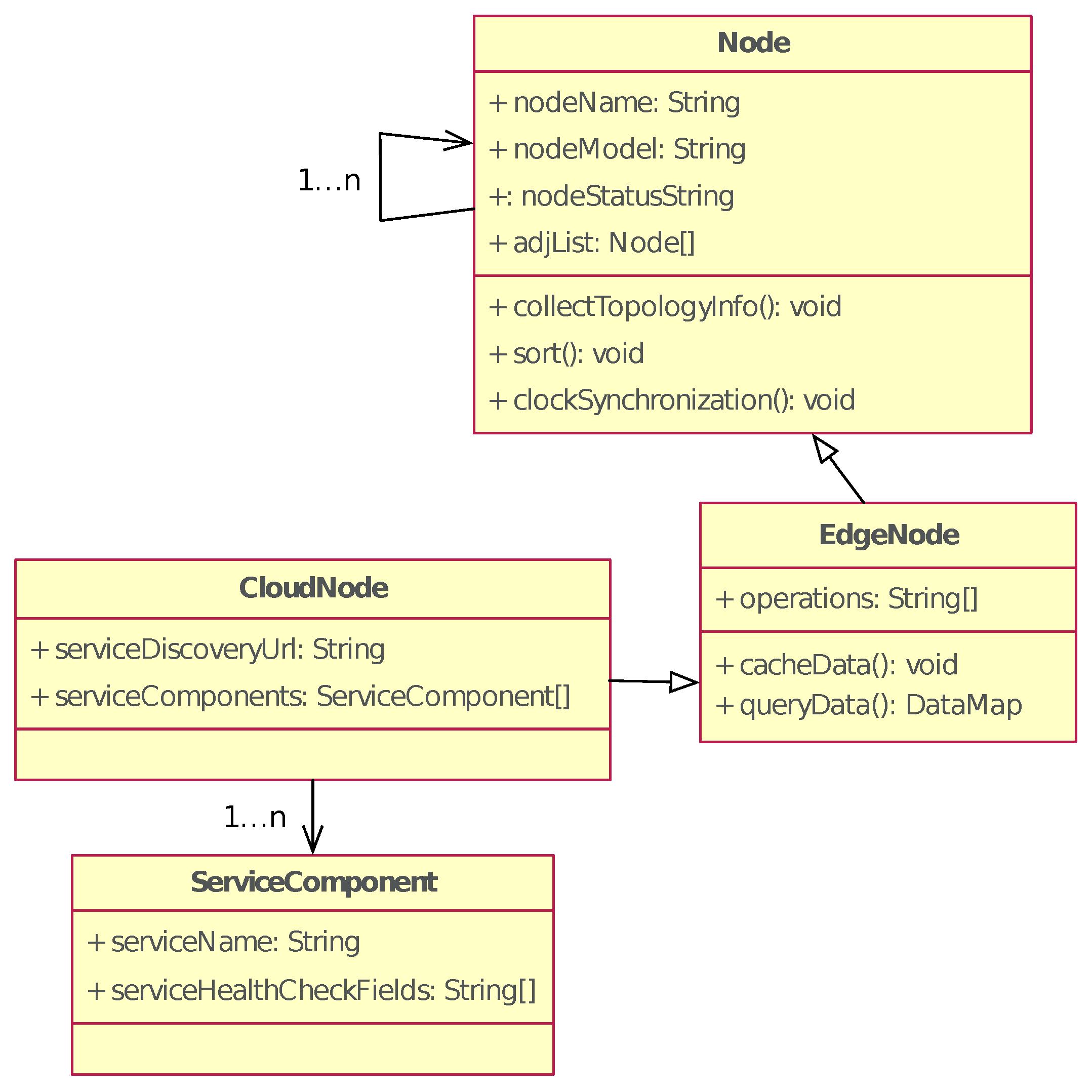
From the design of cloud–edge–end, the data processing operations provided by the cloud also exist in the edge nodes. Hence, we define the Cloud class as an inheritance of the Edge Class. The Cloud node consists of CloudNode and ServiceComponent.
The CloudNode class has two attributes: serviceDiscoveryUrl and serviceHealthCheckFields.
serviceDiscoveryUrl: declares the service discovery address of the cloud node, which will be used to update the health status of each service of the cloud node.
serviceComponents: contains 1 …n instances. With this field, we can obtain the list of micro-services and the list of health statuses of these services in the cloud node.
The ServiceComponent class has two attributes: serviceName and serviceStatus.
serviceName: Field service is used to describe the service name.
serviceHealthCheckFields: describes the health status of the service, such as system throughput, memory usage, and method call frequency.
Figure 5 displays the cloud metamodel with a UML diagram.
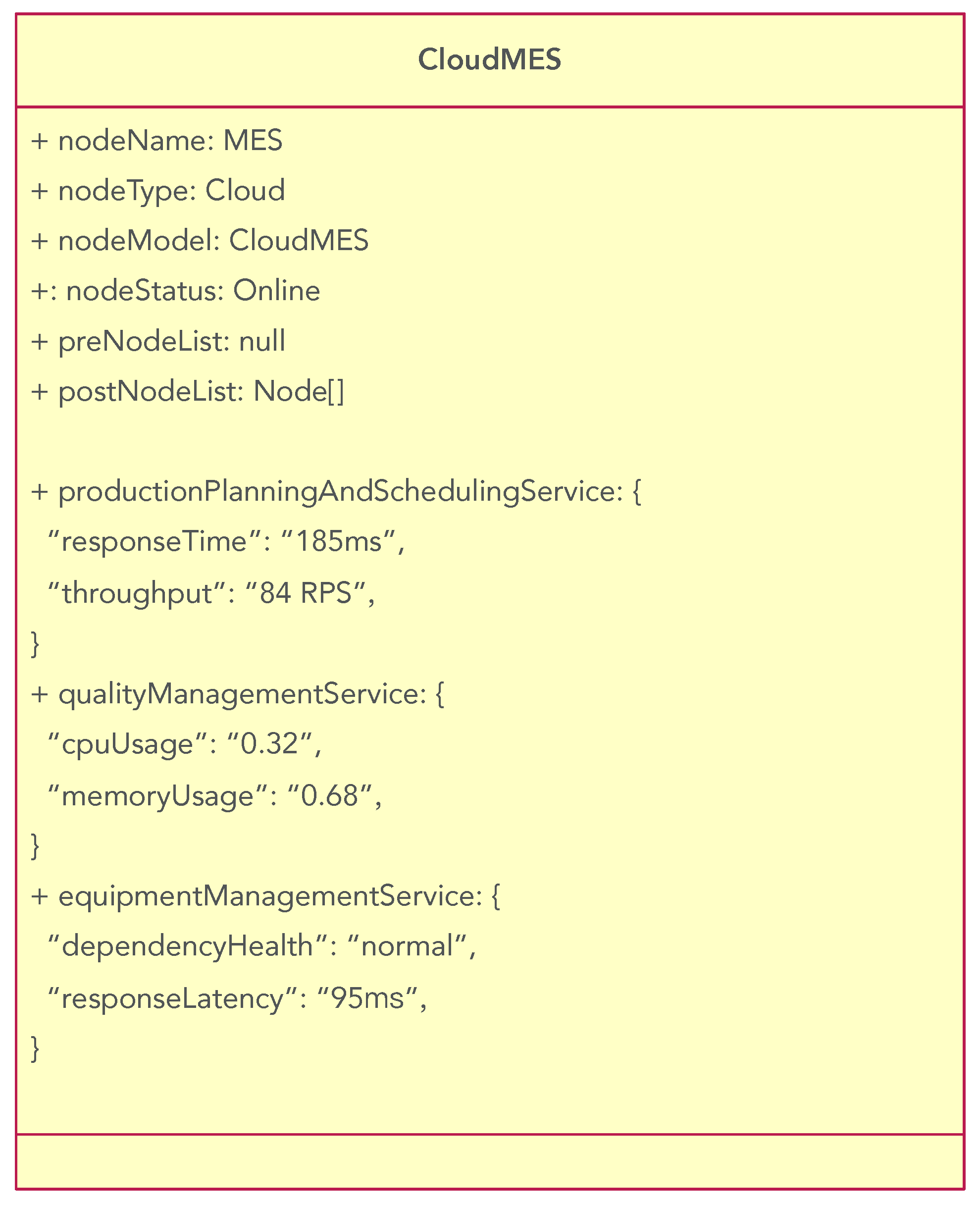
We use the Manufacturing Execution System (MES) as an example. Listing 5 gives the general attributes of the cloud metamodel. Ihe data describes the cloud node representing MES at the Online state.
| Listing 5. The instance of general attributes in the cloud metamodel. |
![Applsci 15 11735 i005 Applsci 15 11735 i005]() |
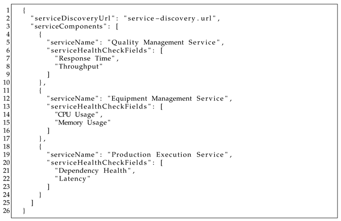
Listing 6 shows the service field attributes of the cloud node. Field serviceDiscoveryUrl declares the address of the register center that manages this cloud node. Through this address, we can check the health status of this node from the register center. Field serviceComponents describes the inside service names and their health indexes. Based on these attributes, we can model each service component. At the same time, we can display the monitored health status of each node in the topological graph.
| Listing 6. The instance of service field attributes in the cloud metamodel. |
![Applsci 15 11735 i006 Applsci 15 11735 i006]() |
3.4. Metamodel Instantiation and Node Instance Update
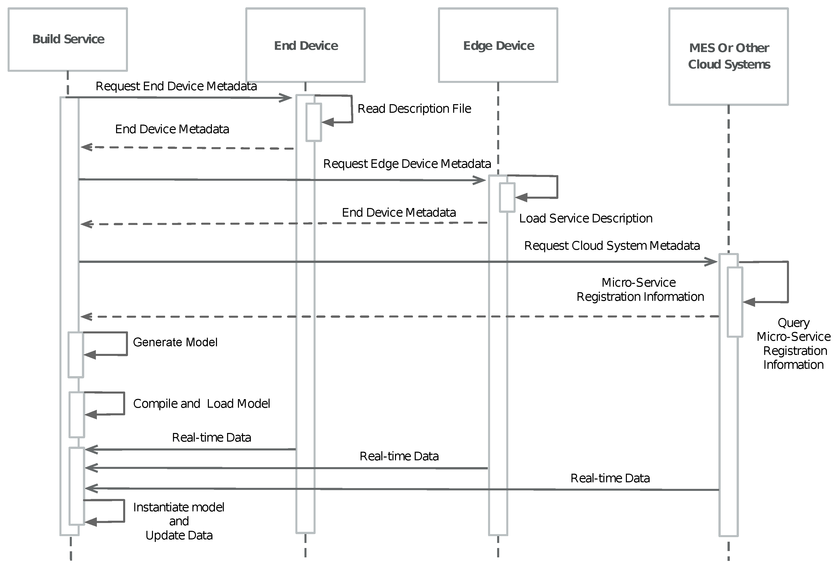
Figure 6 shows the workflow of the instantiation of metamodels. The instantiation of the metamodels relies on the correctness of the data, such as the data in MES and SCADA. We assume that the data in MES and SCADA is always correct. Then, our instantiation satisfies the following property.
Theorem 1. Given the metamodels of cloud, edge, and end, then the data from an intelligent manufacturing system can determine a unique representation of cloud–edge–end topology; and vice versa, if the data satisfies (1) unique identifiers, all devices have globally unique nodeName values; (2) acyclic topology, then production lines contain no cycles; and (3) total ordering, stations within each line have well-defined sequential order.
Proof. (Sketch of Proof).
Formally, let x be the data file, such as an MES file, from an intelligent manufacturing system, y be the corresponding topology representation, and f be the instantiation process. Therefore, we have . We can verify that f is a bijective mapping. Clearly, f is a surjective mapping since each topology representation is instantiated from the corresponding data file. In the sequel, we will verify that f is an injective mapping is the data satisfies the three conditions.
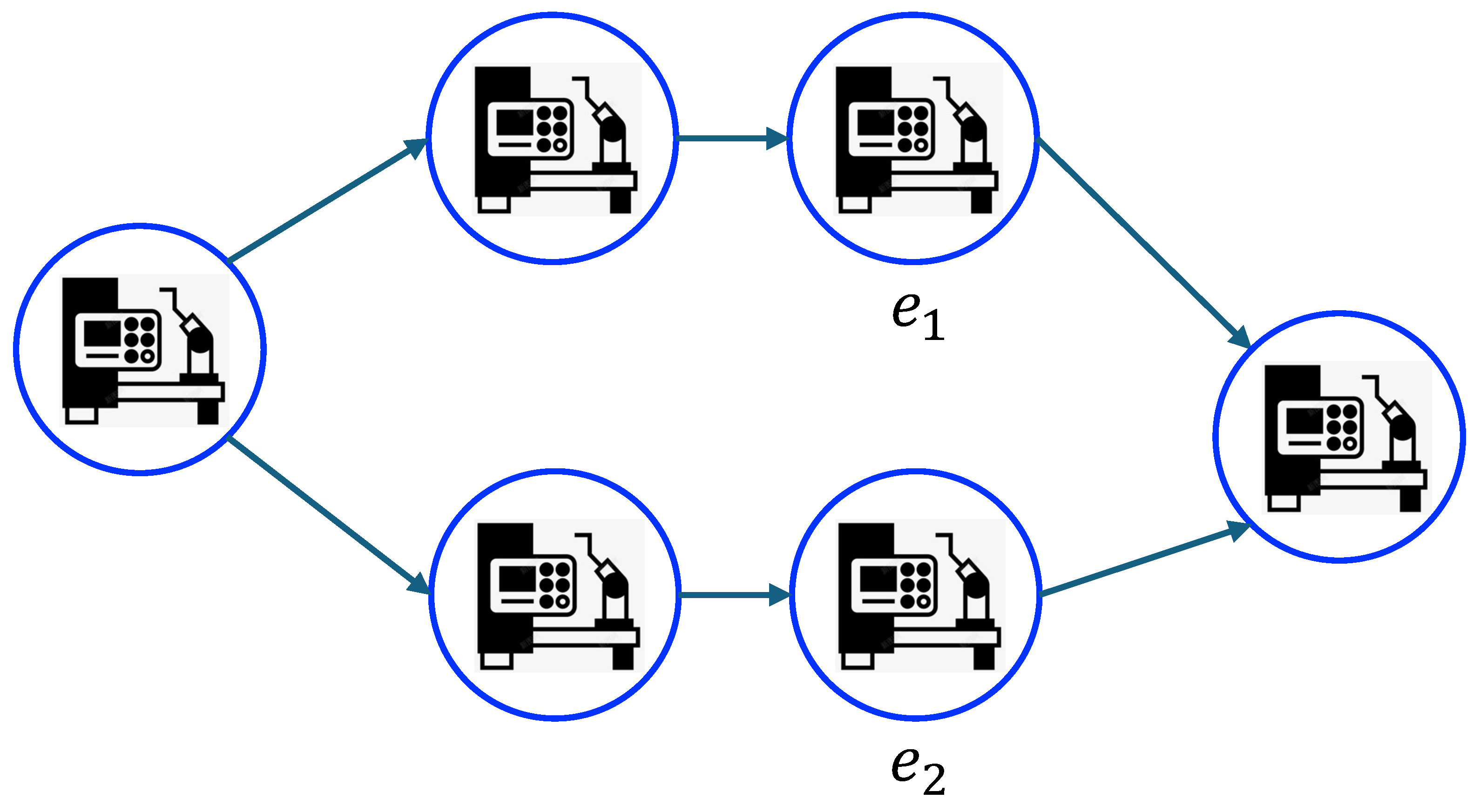
First, we state that each data file will determine a unique topology presentation. According to the current practice in the industry, each device in an intelligent manufacturing system can be characterized by the following four features in the data file: the identification of the device, the information of the production line it belongs to, its preceding devices, and its succeeding devices. Note that our end metamodel contains all these features. On the one hand, to guarantee correctness, different devices have different features. For example, as shown in
Figure 7,
and
represent two devices in the same production line. They have the same succeeding node, but distinct preceding nodes. On the other hand, according to the features, we can extract the nodes and their preceding and succeeding relationships in a production line, from which we can determine a unique graph topology of the production line. This means that the end metamodel will be instantiated into different end models according to the data file, yielding a unique topology representation for the production lines.
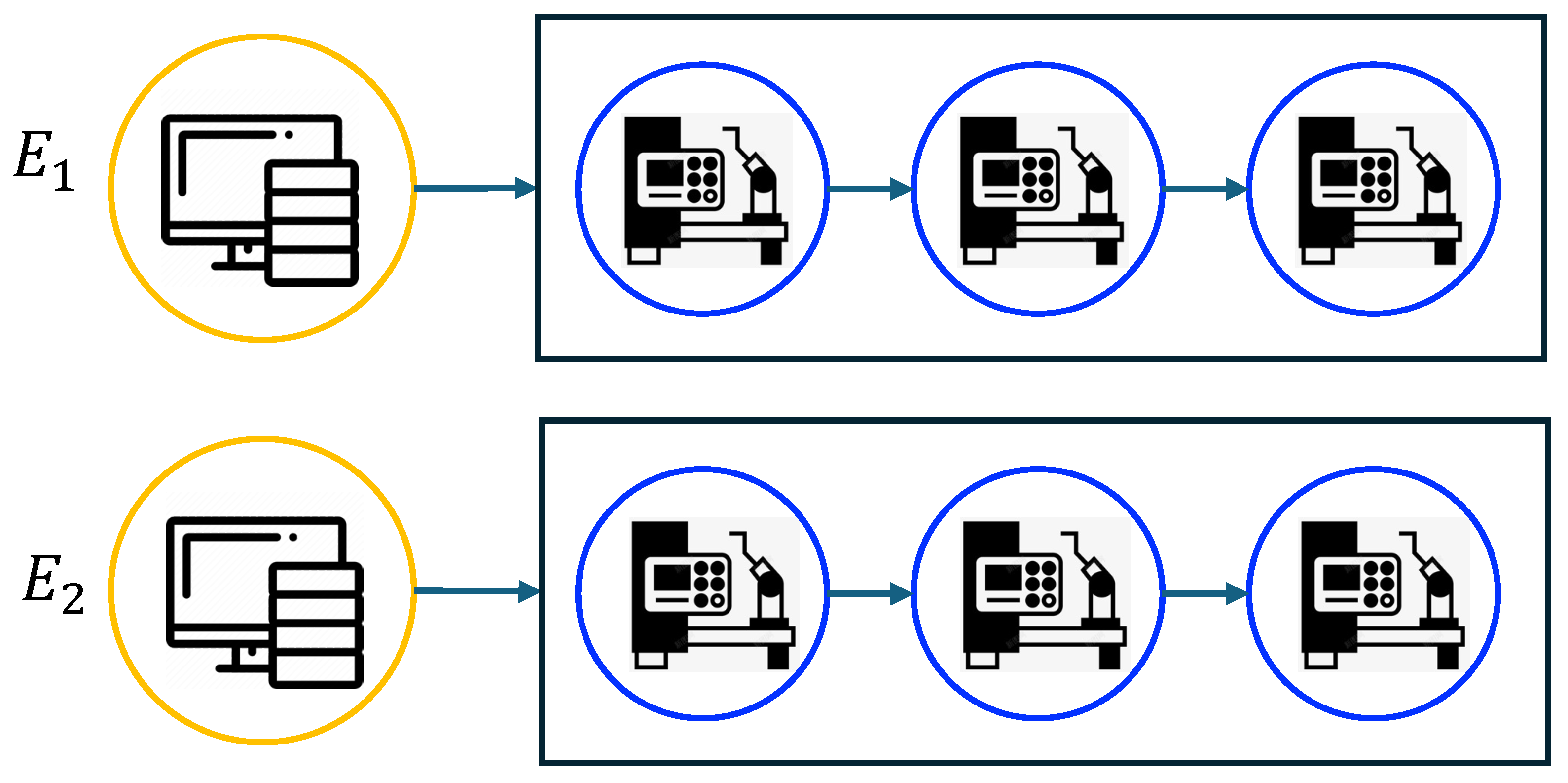
Each edge node connects up to the cloud and down to the production lines. One edge node may connect to multiple production lines, but different edge nodes connect to different production lines. Therefore, an edge node can be determined by its identification and its connected production lines. For example, as shown in
Figure 8, the edge nodes
and
connect two production lines. Therefore, we can uniquely determine the connection between edge nodes and the initial nodes of the production lines in a system. Note that the cloud node connects to all edge nodes. Therefore, each data file can represent a unique topology.
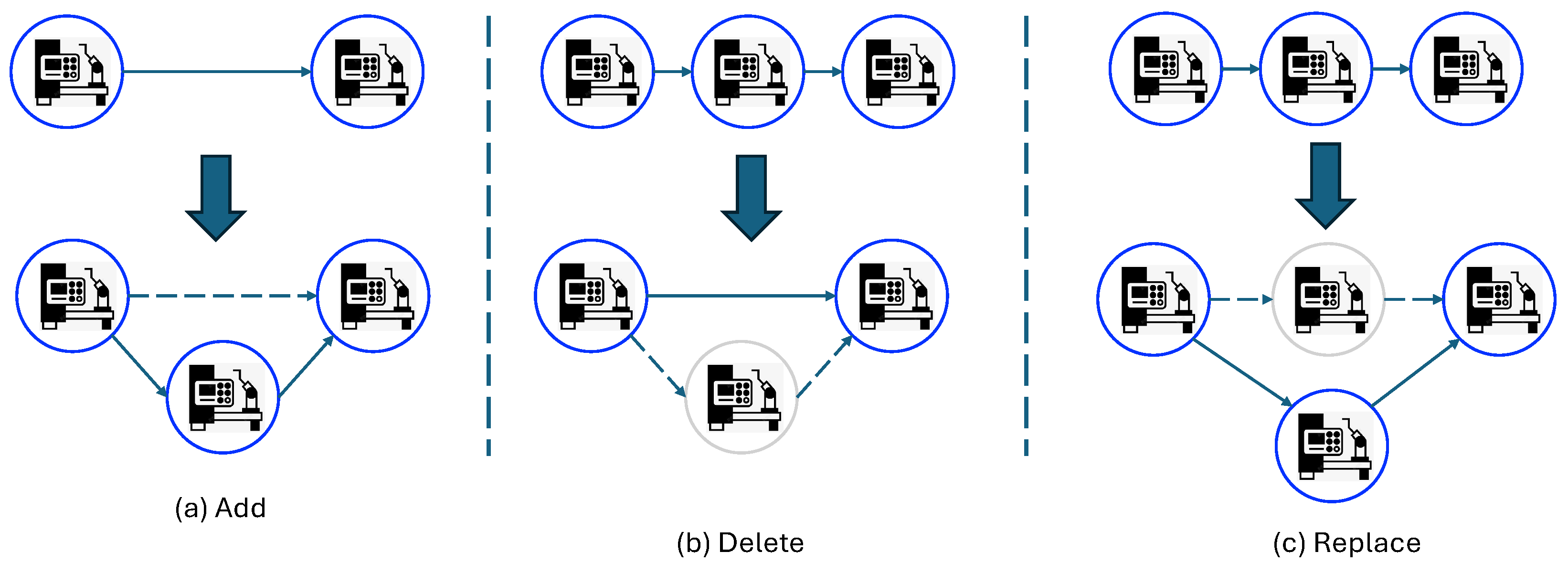
Second, we state that different data files generate different topology representations. For simplicity, we focus on the change of end devices. The change of cloud and edge nodes can be described in the same way. Let us consider three operations on a device in a manufacturing system: add a new device, delete an existing device, and replace a device. All other modifications can be achieved by combining these three situations.
Figure 9 illustrates the three operations. From the figure, we can find that the three operations will change the preceding and succeeding devices of the original devices, resulting in a change in the topology representation. Therefore, different data files will instantiate different topology representations.
□
4. Properties Checking of Topological Representation
After the instantiation, we obtain the topological representation for the specific scene. We have some questions to answer, such as If one node can really reach other nodes, if the presentation can give us high efficiency for storing and querying, and if clock synchronization can be solved to create an alignment table at each node.
4.1. Correctness Checking of Metamodel Instantiation
First, we need to verify the integrity of each end, edge, and cloud instance. Here, the instance integrity includes the accuracy, completeness, consistency, and validity of an instance.
4.1.1. Correctness of End Instances
An end node should satisfy the following properties in every production process.
Each end node has a unique name.
An end node can be a start end node, an internal end node, or a complete end node. A start end node is the first work station to produce products in the production line; an internal end node receives the semi-product from the previous end and sends it to the next end node after processing; a complete end node is the last work station in the production line.
Each end node has only one predefined functionality.
The types of data generated by an end node depend on the node’s functionality and are predetermined.
According to our instantiation, the generated instance of our end metamodel can satisfy the above properties.
Attribute Completeness. All attributes are properly assigned. Moreover, each start end node only has postNode, each internal end node has preNode and postNode, and each complete end node has only preNode.
Name Validity. Given two instances of end nodes A and B, A.nodeName ≠ B.nodeName, so do abilityName and fieldName.
Node Status Validity. The node status is one of the following values: {idle, processing, completed}.
Node Ability Consistency. Given an end instance A, the node type and node ability are consistent: A.nodeType ⇔ A.abilityType.
Data Consistency. The data generated by the end node should be consistent with the ability type. Suppose the set of data types generated by the end node is f(A.abilityName), then A.fieldType ∈ f(A.ability).
4.1.2. Correctness of Edge Instances
Each edge represents a production line. Therefore, the edge nodes should satisfy the following properties.
Given an edge node, its NodeList is a finite sequence of end nodes, including a start node and a complete node. The order of nodes in the sequence is pre-determined by the products to be produced.
The end nodes are connected unidirectionally, representing the sequence of stations to process the product. This means the production cannot be returned to the previous station in a single production.
There are no cycles in an edge node.
The instances instantiated from the edge node metamodel satisfy the above properties.
Attribute Completeness. Given an edge node instance, the following attributes in the edge metamodel should not be empty: nodeName, nodeModel, nodeStatus, preNodeList, and postNodeList.
Name Validity. Different edge nodes have different node names.
Status Validity.
Order Correctness of the stored end nodes. Given an edge node , suppose the sequence of the end node is , we have for , and and for .
Data Consistency. The data is consistent with that stored in the end nodes.
4.1.3. Correctness of Cloud Instances
The cloud node stores all the edge nodes and provides services. Therefore, the instantiation of the cloud metamodel should guarantee that it stores all the edge nodes and initializes all the services. Our instantiation can guarantee the following properties.
Attribute Completeness. All the attributes are well initialized. Specifically, the following initial values of the following attributes are not empty: {serviceDiscoveryUrl, serviceComponents}.
Name Validity. Each service has a unique name.
Correctness of Included edge Nodes. Given a cloud node , suppose . We have .
4.2. Correctness Checking of Topology Behaviors
For the node behavior, we need to do reachability checking, topology update checking, and data update checking. Reachability checking aims to determine whether a node can be reached from a cloud node and whether the path satisfies the actual production process. The topology update check aims to determine whether the topology structures stored on edge nodes and the cloud node can be automatically updated when the node relations in the MES are changed. The data update checking ensures that the data stored on the nodes can be changed accordingly when the data in some node is changed.
4.2.1. Reachability Checking
In our cloud–edge–end intelligent manufacturing systems, the reachability means that the information stored in a cloud node can reach the complete end node. Here, the information can be production tasks, parameter configurations, and raw materials/semi-products of the products. According to our metamodel instantiation, each complete end node is reachable.
Property 1 (Topology Connection). Given an instantiated cloud–edge–end topology of an intelligent system, denoted as , where is a singleton set representing the cloud instance, is the set of edge nodes, is the set of edge nodes, and denotes the connection of different nodes, then should satisfy: , where , , and .
Note that for simplicity, we use to denote the could node.
Property 2 (Strong Reachability). Given the topology of a system , suppose the set of complete end nodes is . Then, we have , there exists a path , satisfying , for , and .
This property means that production starts when the cloud node sends the production tasks.
Property 3 (Weak Reachability). Given the topology of a system , suppose the set of complete end nodes is . Then, we have , there exists an end node such that s can reach to via a path , satisfying , for , and .
This property means that at any time, an edge node or an end node can update its attributes and then affect its downstream nodes.
4.2.2. Topology Update Checking
During the production update, one may add or remove production lines due to changes in orders; for each production line, one may add or remove end nodes due to changes in products to be produced. Therefore, the topology instance should be updated correspondingly. The following theorems guarantee that our topology can be updated in response to changes in node instances.
Property 4 (Remove End Node). Given a topology , the remove of a end node will generate a new topology , where , , , , and are the preceding and succeeding node, i.e., and
Property 5 (Add End Node). Given a topology , adding a new end node s between and , where and , will generate a new topology , where , , , .
Property 6 (Remove Production Line). Given a topology , the remove of a production line , whose corresponding edge node is , will generate a new topology , where , , , .
Property 7 (Add Production Line). Given a topology , the adding of a production line with a new edge node e will generate a new topology , where , , , .
5. Experiments
In this section, we conduct simulation experiments to validate the correctness of the proposed metamodels and the performance of the instantiated models. Specifically, we use Webots to simulate a production scenario, with which we aim to answer the following research questions:
- RQ1:
Can the proposed metamodels describe the data produced in intelligent manufacturing?
- RQ2:
Can the proposed metamodels correctly and promptly monitor the change of intelligent manufacturing?
- RQ3:
Can the proposed topology-based data representation improve the production performance in large-scale production scenarios?
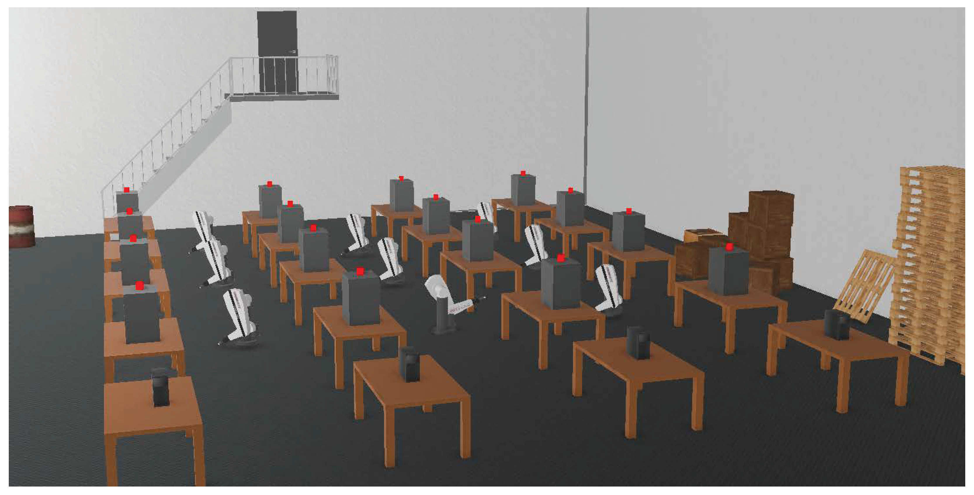
As shown in
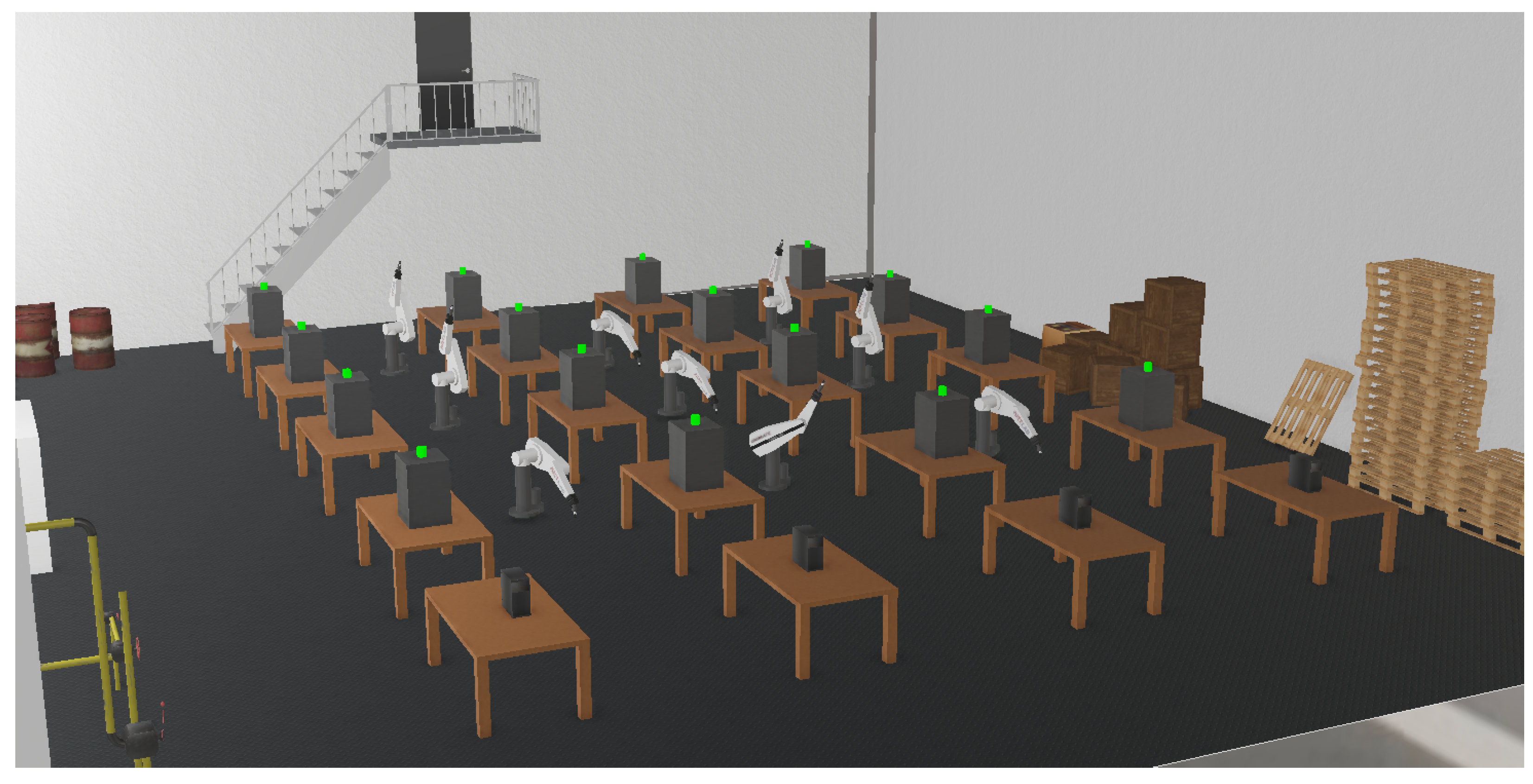
Figure 10, there are four production lines in the scenario, each consisting of 4 workstations. Each production line is equipped with an edge server to process production data. There is a cloud server to store and process the data from the edge servers. The configuration of the computation module in each node is shown in
Table 2.
We implemented a cloud-based topology engine using the method proposed in this article. After the simulation begins, we define each device in Webots, including processing devices (end devices) and edge computing devices, to periodically send heartbeat data packets containing their status information to the cloud-based system (e.g., the SCADA system), reporting the current survival status of the nodes. The topology engine obtains scene topology metadata through systems like MES and SCADA, instantiates the scene topology graph, and simultaneously listens for heartbeat data packets sent by devices in the cloud system, monitoring changes in the production line topology structure. At the same time, the end devices generate a two-dimensional array every second after the simulation starts, simulating data from 12 sensors with a sampling rate of 5000 Hz.
5.1. Correctness of Metamodel Instantiation
Our running production scenario is shown in
Figure 11. The metadata for instantiation of the cloud, edge, and end nodes are shown in
Table 3,
Table 4 and
Table 5. When the simulation starts, all processing equipment is activated, and the device indicator lights turn green, beginning to send heartbeat data packets to the message queue. At the same time, the topology engine immediately collects the metadata of the metamodel from the MES and completes the initialization of the metamodel.
Figure 12,
Figure 13 and
Figure 14 show the generated models for the cloud, edge, and end nodes.
5.2. Correctness of Topology
In this section, we examine whether our topology can accurately describe the production scenario. After the simulation began, the topology engine immediately collected the metadata of the meta-model from the MES and completed the initialization of the meta-model. In the following few seconds, the topology engine listened to the node’s status information from the message queue and rendered the correct scene topology, as shown in
Figure 15.
Then, we randomly offline the equipment and observed whether the topology map could respond to topology changes in a timely and correct manner. Experimental results show that the topology graph monitored the device offline within a few seconds and modified the topology graph in time, as shown in
Figure 16.
The experimental results show that our meta-model can timely respond to the device’s status and change the topology by listening to the heartbeat information of the device.
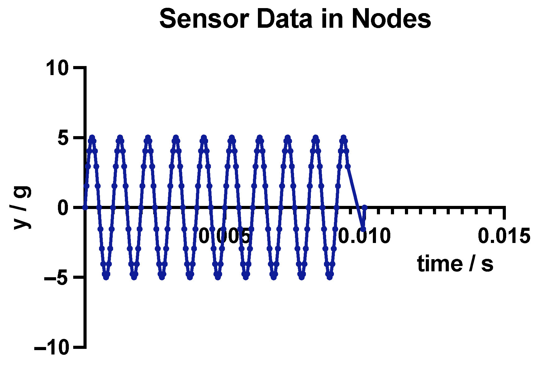
In addition, our meta-model nodes also have the capability to store dynamic data. To verify this feature, we changed the data generation function of one of the sensors in the end device from generating random numbers to generating a sine wave that follows the function
in the simulator. We exported the data from the node and plotted it. Due to the large scale of the data, we only plotted the images of the first two cycles, as shown in
Figure 17.
5.3. Performance Testing of Metamodel
In the traditional cloud-end model, data generated by end nodes is directly uploaded to cloud nodes and managed uniformly by cloud nodes. In the metamodel we discussed, the end node uploads data to the edge node connected to it, and the edge node temporarily stores the data of this production line inside the node, selects data with a higher value according to a certain method, and uploads it to the cloud node. To test the performance of the meta-model based on the cloud–edge–end architecture, we used the traditional cloud-end architecture as a baseline and formulated the following two measurement indicators.
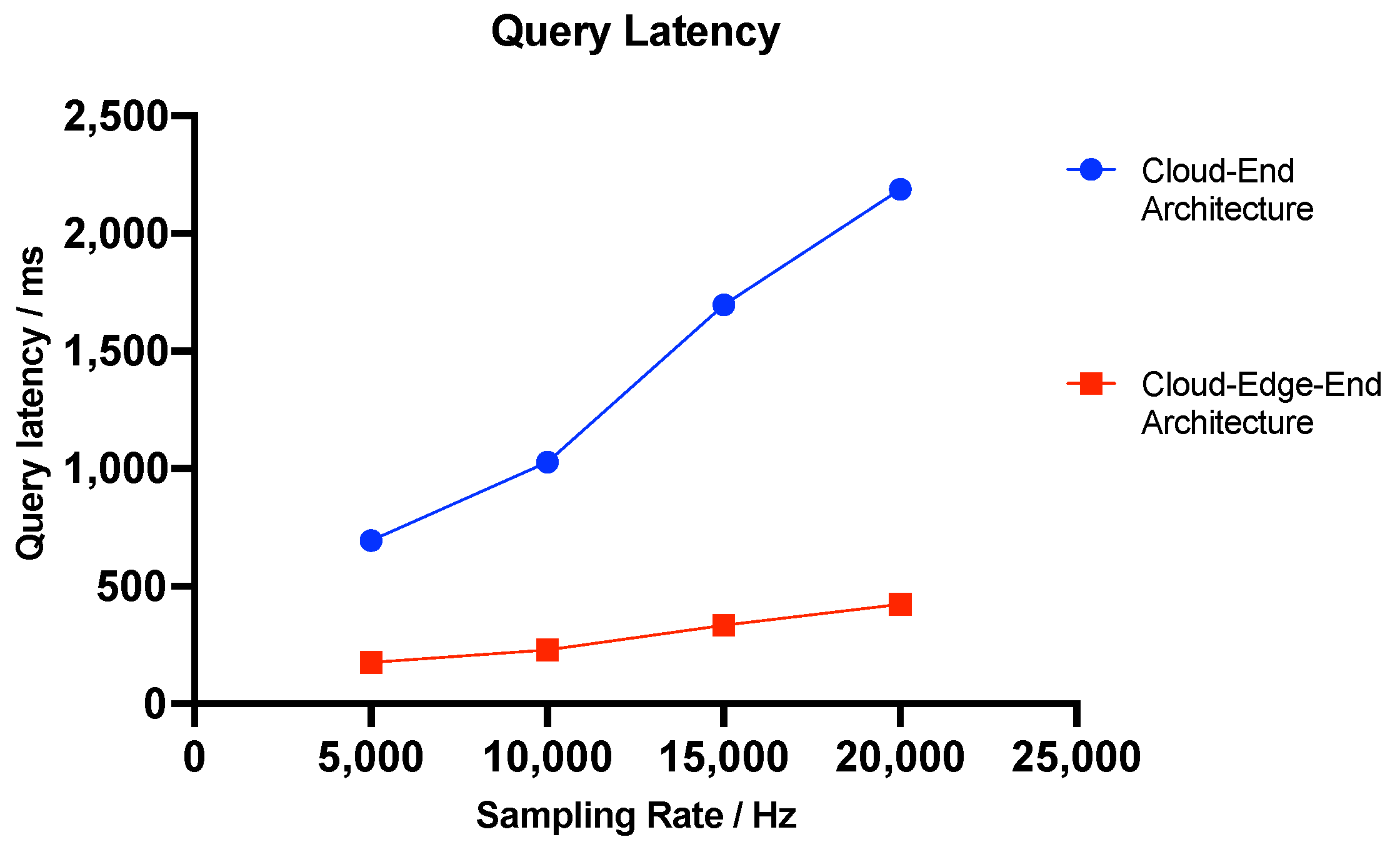
First, we tested the response latency of querying data of the same size. In our test case, we need to query data of the same size in each device separately, and the timing starts from the first query request and ends when the last query request returns. We ensure that all query requests are executed by independent threads, and the test server has enough hardware resources to complete the query requests, which means that the query requests are fully parallelized. First, at a data scale of 5000 Hz sampling rate, we directly request cloud nodes for the cloud-end architecture and query data of a total of 16 devices in 4 production lines. Then, for the cloud–edge–end architecture, we simultaneously query the data in the edge nodes of 4 production lines, measure the latency of the above two scenarios, cycle 10 times, and calculate the average latency. Then, we increased the data sampling rate to 10,000 Hz, 15,000 Hz, and 20,000 Hz. We repeated the above operations to obtain a total of 4 sets of data. The average latency is as shown in
Figure 18.
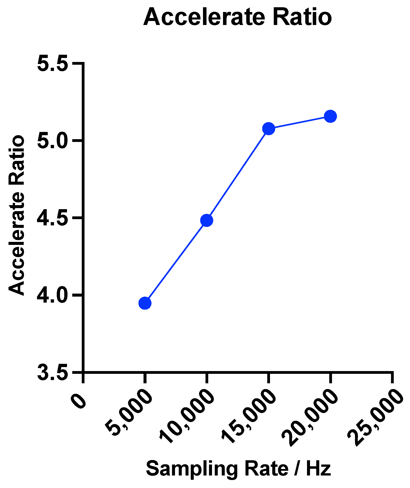
To further observe the impact of data scale on performance, we use the acceleration ratio to measure the performance improvement of the cloud–edge–end architecture compared to the traditional cloud-end architecture. The calculation formula for the acceleration ratio is as follows:
where
represents the query latency under the traditional cloud-segment architecture, and
represents the query latency under the cloud–edge–end architecture. Acceleration under different data scales is shown in
Figure 19. The results show that as the data scale increases, the acceleration effect of the cloud–edge–end architecture on query tasks becomes increasingly significant.
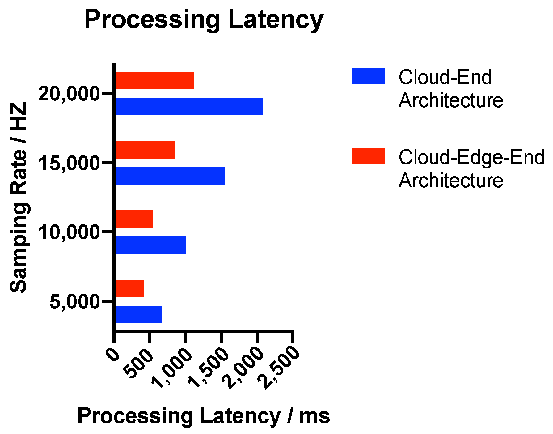
Then, we tested the processing latency of data of the same scale. In this test case, to simulate a complex data processing scenario, we selected a single vibration signal sampled at 5000 Hz, 10,000 Hz, 15,000 Hz, and 20,000 Hz for a total of 120 s. First, we performed 50 descriptive statistical analyses on the vibration signal to extract its statistical features, and then we executed 50 STFT analyses (The values of STFT window, overlap, FFT length are 2048, 1024, and 2048, respectively, using the scipy compute kernel) on the vibration signal to extract its time-frequency features. The timing started from the execution of the descriptive statistical analysis to the completion of the last STFT, ending when the endpoint received the analysis results. We ensured that all analysis processes were executed by independent threads. In the traditional cloud-edge architecture, all analysis tasks are executed by the cloud node, which then sends the data to the endpoint. In the cloud–edge–end architecture, the analysis tasks are executed by the edge node close to the endpoint and then sent to the endpoint. A total of 10 tests were conducted, collecting four sets of data at different scales, and the resulting latency comparisons are shown in
Figure 20.
Through the above experiments, we tested the processing latency in two scenarios: data upload and query, and data processing and result distribution. The experimental results showed that in manufacturing scenarios with large-scale data generation, the meta-model based on the cloud–edge–end architecture exhibits superior performance.
5.4. Discussion
Topological architecture performance evaluation. In this work, we proposed a cloud–edge–end topological architecture for data representation in intelligent manufacturing, aiming to reduce communication bottlenecks and query latency, so as to support fast data querying. Therefore, we conducted experiments with various sampling rates using standardized data formats. While the metamodels provide high-level abstraction, we also acknowledge that protocol adapters for different communication protocols and drivers for connecting diverse devices must still be implemented. Actually, these components constitute the support layer between the hardware and the intelligent manufacturing operating system. However, these implementations are standard system integration practices and beyond the scope of this work. In the future, we will conduct comprehensive experiments with different data types and protocols on the built intelligent manufacturing operating system.
Scalability of the topological architecture. The proposed topological architecture can scale to different device configurations, as demonstrated by the following complexity analysis. Suppose there are N workstations distributed across M production lines, with one cloud node. (1) The instantiation complexity is , and the topology update complexity is , where n is the number of affected nodes. (2) For data querying, the system first retrieves the corresponding production line, then the target workstation. Since each production line contains at least one workstation, the maximum number of workstations per line is . Therefore, the query complexity is . However, the approach faces two potential bottlenecks: (1) graph rendering performance for large topologies and (2) cloud node data processing when all edge nodes simultaneously send dynamic data after instantiation. We may address the first bottleneck through hierarchical visualization with drill-down capabilities, and mitigate the second through batched updates with eventual consistency.
Limitations of the work. We acknowledge several limitations of this work that do not diminish the core contributions. First, our method assumes the correctness and integrity of MES and SCADA data for metamodel instantiation; data quality issues require manual intervention or preprocessing steps. Second, we focus on the architectural design of the cloud–edge–end topological framework rather than low-level implementation details, such as protocol adapters and clock synchronization mechanisms for dynamic data streams from heterogeneous devices. Third, we evaluate the proposed method through simulation experiments in Webots rather than in real production environments. Fourth, the current prototype does not implement security control mechanisms, such as authentication, authorization, and access control, in multi-tenant industrial deployments.
6. Conclusions
This paper presents a novel metamodel-based approach for storing and displaying massive manufacturing data in intelligent manufacturing systems, addressing the critical challenges of high-frequency data collection, diverse device protocols, and expensive customization requirements. By proposing the cloud–edge–end architecture for intelligent manufacturing systems and developing hierarchical metamodels for the end, edge, and cloud nodes, our framework provides a universal topology representation that can be instantiated for specific manufacturing scenarios without the prohibitive costs of training large-scale AI models. The proposed method provides automatic instantiation of metamodels to generate concrete data representation models and enable fast data querying, supporting distributed computing across cloud–edge–end architectures and thereby forming a foundational layer for intelligent manufacturing operating systems. Experimental validation demonstrates that our approach significantly reduces data querying costs, facilitating the effective utilization of industrial data for AI-driven production optimization and equipment health management. This work contributes to making intelligent manufacturing more accessible and economically viable for companies seeking to leverage data-driven insights without the burden of extensive model training and customization.
In future work, we plan to extend this research in several directions. First, we will realize the low-level system implementation, including protocol transformation adapters and clock synchronization mechanisms. Second, we will conduct comprehensive experiments with heterogeneous data types and communication protocols, validated in real factory settings with physical production lines, diverse equipment, and actual industrial protocols. Third, we will investigate robust metamodel instantiation under adverse conditions, including data errors, network partitions, Byzantine failures, and protocol timeouts. Fourth, we will develop multi-tenant security models to ensure secure communication, data transmission, and topological queries in shared manufacturing environments.

