Article

Analysis of the Structural Responses of Adjacent Components to the Operation of a Polymer-Based Explosive Fire Suppression System

1
Department of Future Mobility, Dong-Eui University, 176 Eomgwang-ro, Busan 47340, Republic of Korea
2
Digital Twin Laboratory, Dong-Eui University, 176 Eomgwang-ro, Busan 47340, Republic of Korea
*
Author to whom correspondence should be addressed.
Appl. Sci. 2025, 15(21), 11718; https://doi.org/10.3390/app152111718
Submission received: 28 August 2025 / Revised: 16 October 2025 / Accepted: 29 October 2025 / Published: 3 November 2025
(This article belongs to the Special Issue Polymer Materials: Design, Fabrication and Mechanical Properties)

Abstract

With the rapid expansion of electric vehicles, the risk of battery fires has become a critical safety concern. Conventional suppression methods, such as submerging battery packs in large water tanks, are inefficient due to long response times and potential secondary hazards. This study introduces a polymer-based fire suppression tube system that automatically activates under specific conditions. The system utilizes energy from a C4 explosion to rupture the tube, rapidly releasing the extinguishing agents stored inside. Explicit dynamics simulations in ANSYS Workbench 2024 R2 were conducted by varying tube thickness from 0.5 mm to 2.0 mm to evaluate the structural response of adjacent components. Three indices were examined: total deformation, deformation of the adjacent plate, and deformation of the tube itself. The results showed that thinner tubes (0.5 mm) allowed for greater propagation of blast energy, increasing the risk of damage, whereas thicker tubes (≥1.5 mm) effectively confined the explosive energy and reduced shock transmission. These findings confirm that tube thickness is a key parameter governing blast-induced deformation, with 1.5 mm identified as the threshold for minimizing structural damage. This study provides practical design guidelines for polymer-based automatic suppression systems, contributing to safer fire protection solutions for electric vehicles and related industrial applications.

1. Introduction

With the rapid expansion of battery-powered applications such as electric vehicles (EVs), the frequency of battery fire incidents has increased, raising serious safety concerns across industries [1,2,3,4,5,6]. EV batteries—including lithium-ion (Li-ion), lithium iron phosphate (LFP), and nickel cobalt manganese (NCM)—are particularly vulnerable to thermal runaway triggered by external impacts, internal short circuits, or overheating [7,8]. Once initiated, thermal runaway can rapidly propagate throughout the entire vehicle, leading to severe fire hazards that threaten both passenger safety and structural integrity.
Current fire suppression methods for EV batteries, such as immersing modules in large water tanks [9,10], suffer from long suppression times, low efficiency, and potential secondary risks. As compact, high-energy battery systems have become more common, these conventional approaches have proven inadequate for fast and localized fire control. Therefore, new suppression technologies that enable rapid activation while minimizing collateral damage are urgently required. To address these limitations, this study proposes a polymer-based fire suppression tube system that integrates an embedded C4 explosive charge with a stored extinguishing agent. When exposed to critical thermal or external stimuli, the C4 detonation ruptures the tube, allowing the suppressant to be instantaneously discharged and suppress the fire. This concept offers advantages such as structural simplicity, lightweight design, and rapid response. However, explosive activation may generate blast pressure and fragments that can impact adjacent components, battery modules, or vehicle structures. Quantitative analyses of such structural effects remain limited, making it difficult to establish reliable design and application standards.
Previous studies on EV battery fire suppression have primarily focused on conventional cooling-based or chemically driven methods, while most blast modeling research has been directed toward military or civil structural applications. To the best of our knowledge, no systematic study has quantitatively analyzed the structural impacts of explosive-actuated polymer suppression tubes on adjacent battery components.
Accordingly, this study employs Explicit Dynamics simulations to evaluate the structural effects on adjacent components when a polymer suppression tube with varying thicknesses (0.5–2.0 mm) is activated by C4. The objective is to determine the optimal tube thickness that minimizes blast transmission and mechanical damage to surrounding structures while ensuring reliable suppression performance. The findings are expected to provide fundamental design data for establishing structural safety standards and to serve as academic and industrial references for the advancement of polymer-based automatic fire suppression technologies. Furthermore, the outcomes of this study can be applied to the design of safer EV battery modules and small electrical systems, ultimately contributing to the broader development of high-safety industrial environments.

2. Materials and Methods

The overall workflow of the simulation procedure is illustrated in Figure 1. It comprises five sequential stages: explosion scenario definition, model components, material assignment, simulation setup, and key output metrics. Each stage is described in detail in the following subsections.

2.1. Model Geometry

In this study, a numerical simulation was performed to quantitatively analyze the structural effects of shock waves generated by the detonation of C4 explosive embedded inside the suppression tube, focusing on how variations in tube thickness influence both the tube itself and adjacent structures. Figure 2 shows the basic geometry of the polymer fire suppression tube used in this research. The tube is designed for installation inside or adjacent to small battery packs, battery-based electrical devices, and EV battery packs. When thermal runaway is triggered by external impacts, internal short circuits, or over-charging, the internal temperature exceeds a critical threshold, and the centrally embedded C4 is modeled to detonate [11,12]. The resulting blast pressure induces rupture at the tube’s center, causing the stored suppressant to be instantaneously discharged, thereby suppressing fire propagation [13].
To reflect these structural characteristics, a numerical model was constructed in the ANSYS Workbench 2024 R2 (ANSYS Inc., Canonsburg, PA, USA) environment, as illustrated in Figure 3. The model consists of a cylindrical suppression tube with C4 placed at its center, and an aluminum plate positioned beneath the tube to replicate the cooling or protective plate typically located under cells or between modules in battery packs [14,15]. This aluminum plate was included as a key component to evaluate the degree of shock transmission to adjacent structures when the tube is activated.
The geometric parameters of the tube are illustrated in Figure 4. The tube geometry was modeled based on actual product dimensions, with a total length of 166 mm and an inner diameter of 8 mm. The aluminum plate beneath the tube was defined with dimensions of 169.45 mm × 91.1 mm × 1.0 mm, and a 4 mm gap was maintained between the two components. The embedded C4 charge was modeled as a rectangular solid measuring 3 mm × 4 mm × 4 mm, located at the tube center. These values were chosen to reflect actual battery-pack component sizes and to ensure the reliability of the numerical model.
Both ends of the tube were sealed so that the blast pressure acted internally rather than escaping outward, producing a concentrated shock effect within the tube. The detonation was defined as an initial condition, generating a radially outward pressure wave [16]. The tube thickness was varied from 0.5 mm to 2.0 mm in increments of 0.1 mm, resulting in sixteen simulation cases. This configuration enabled systematic observation and quantitative comparison of structural responses, including shock transmission, localized deformation, and stress concentration.
Overall, the modeling setup presented in Figure 3 and Figure 4 accurately represents the installation conditions of small battery modules and provides fundamental structural design data for evaluating the performance of C4-based suppression tubes and establishing future design criteria.

2.2. Material Properties

The simulation model consisted of three materials: the suppression tube, the explosive (C4), and the aluminum plate. Each component was defined in the ANSYS Workbench 2024 R2 Explicit Dynamics Engineering Data module by adding relevant material models and entering numerical values. The suppression tube was defined as polyamide 12 (PA12), a polymer widely used in electrical, electronic, and battery housing applications due to its excellent mechanical strength, chemical resistance, and wear resistance. Unlike brittle materials such as glass, which may generate sharp fragments upon fracture, PA12 exhibits ductile fracture behavior under blast loading, thereby reducing the risk of hazardous debris generation. This property makes PA12 particularly suitable for suppression tubes, as it minimizes secondary damage in explosive events. In addition, PA12 maintains structural stability at elevated temperatures, with a heat deflection temperature of approximately 170–180 °C. For this study, PA12 was modeled as a linear elastic solid for simplified evaluation of local responses, and additional Engineering Data modules were included: Isotropic Elasticity, Bilinear Isotropic Hardening, Specific Heat at Constant Pressure, Plastic Strain Failure, and Density. For Bilinear Isotropic Hardening, the yield strength was set to 3.5 × 10⁷ Pa and the tangent modulus to 2.0 × 10⁷ Pa. Other basic properties such as density, Young’s modulus, and Poisson’s ratio are summarized in Table 1 [17,18]. For simplicity, the PA12 tube was defined using only the properties measured at 22 °C, without incorporating temperature-dependent variations. As a result, potential softening effects at the high local temperatures generated during C4 detonation were not considered in this study.
The explosive was modeled as C4, a high-performance material that generates a high-temperature and high-pressure state immediately after detonation. In the Engineering Data settings, the density was set to 1601 kg/m3 under Physical Properties, and the Explosive Jones–Wilkins–Lee (JWL) equation of state was applied [19]. The JWL equation defines pressure P as a function of specific volume V and internal energy E, and is well suited to describing the thermodynamic behavior of detonation gases under extreme conditions [20,21]:
P = A 1 ω R 1 V · e R 1 V + B 1 ω R 2 V · e R 2 V + ω · E V
where A and B are pressure constants, R1 and R2 are exponential decay coefficients, ω is the internal energy contribution ratio (Grüneisen parameter), V is the specific volume, and E is the internal energy per unit mass.
The JWL parameters for C4 were obtained from the ANSYS explicit materials library Explicit_Materials.xml, which provides coefficients that are commonly used in explosive modeling studies. The adopted parameters are summarized in Table 2. Field variables for C4 were set with a base temperature of 22 °C, while the lower and upper limits were left as program-controlled. These settings were chosen to ensure numerical consistency with standard C4 detonation models.
The lower plate was modeled as Aluminum Alloy NL to replicate the cooling plate or protective cover located beneath cells or between modules in small battery packs. Aluminum alloys are widely used in EV battery structures and typically exhibit a yield strength of 240–280 MPa and a Young’s modulus of approximately 70 GPa. In this study, the material properties of the aluminum plate were defined using the same modules as those applied to PA12, allowing the yield and deformation characteristics of the plate to be considered. Thus, the aluminum plate was treated as a deformable body, enabling both the transmission of shock and the plate’s own deformation behavior to be evaluated. The Field Variables were set with a base temperature of 22 °C, while the lower and upper limits were Program Controlled. The key properties are summarized in Table 3.
In summary, the material models defined in this study reflect the elastic, thermal, and plastic behavior of the PA12 suppression tube, the high-temperature and high-pressure detonation characteristics of C4 through the JWL equation of state, and the actual mechanical response of the aluminum plate. Together, these definitions enable a realistic reproduction of structural interactions and provide a quantitative basis for analyzing shock transmission, absorption, and attenuation mechanisms in the suppression system.

2.3. Definition of Model Conditions and Analysis Settings

This analysis was conducted to quantitatively evaluate the structural effects of shock waves generated by the detonation of C4 explosive embedded inside the polymer suppression tube, focusing on how variations in tube thickness influence the responses of both the tube and the adjacent aluminum plate [22]. The simulation procedure was organized into sequential stages: Geometry, Connections, Mesh, Explicit Dynamics Analysis Settings, and Initial Detonation Conditions.
In the Connections stage, the interaction between the suppression tube and the aluminum plate was defined in ANSYS Workbench 2024 R2 using a body interaction definition. The applied settings were: Shell Thickness Factor = 0, Tolerance = 0.2, Type = Frictionless, and Suppressed = No. This frictionless condition reflects an idealized scenario in which the explosive shock is transmitted directly to the plate without dissipation due to surface friction.
For the Mesh, explicit elements were employed to capture the rapid pressure fluctuations and localized rupture phenomena induced by detonation [23]. The physics preference was set to Explicit, the element order to Linear, and the element size to 1.0 mm. A mesh-independence assessment was also conducted with element sizes of 0.5, 1.0, and 1.5 mm to verify the stability of the numerical results. The detailed outcomes are presented in Section 3.2. Mesh sizes finer than 0.5 mm were found to be numerically unstable due to excessive element distortion during detonation, leading to non-convergent solutions. Therefore, an element size of 1.0 mm was selected through convergence testing to achieve a balance between computational efficiency and the resolution of local stress concentrations and deformation behavior.
The Explicit Dynamics Analysis Settings were configured as follows: the number of steps was set to 1, with Load Step Type = Explicit Time Integration. The end time was defined as 1.0 × 10⁻⁵ s, the maximum number of cycles as 1 × 10⁷, the maximum energy error as 0.1, and the time step safety factor as 0.9. These values were applied to ensure stable and accurate numerical simulation of the rapid physical changes occurring during detonation.
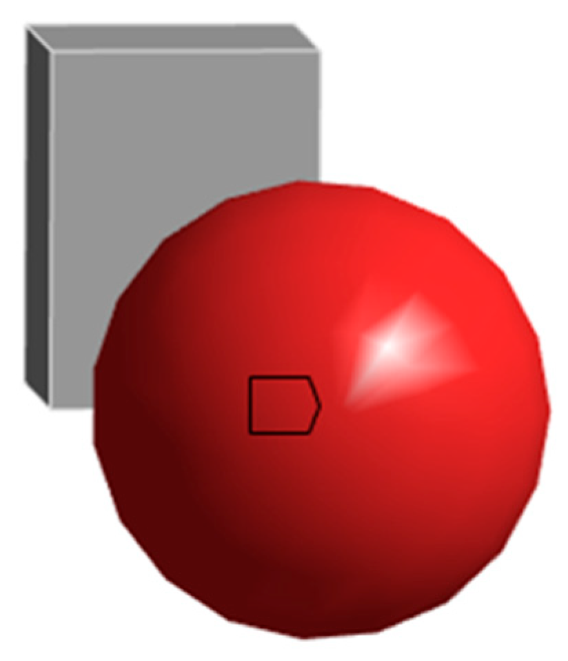
Finally, the Initial Detonation Condition was defined in the Initial Condition module using the Detonation function. The initiation point of the C4 charge was defined at the lower region of the explosive body with coordinates X = 4 mm, Y = 4 mm, Z = 3 mm, and the detonation time was set to 0 s. This condition modeled the release of a hemispherical pressure wave originating from the lower region of the C4 charge, as illustrated in Figure 5. The selected initiation location produces an upward hemispherical pressure wave and provides a consistent baseline loading condition for comparing thickness-dependent structural responses across all simulation cases.
To enable quantitative comparison of structural responses, two primary evaluation indices were defined. The first, Total Deformation, represents the global displacement of the entire model, including the suppression tube and the aluminum plate. The second, Plate Deformation, corresponds to the maximum displacement measured at the center of the aluminum plate, indicating the degree of shock transmission to adjacent components. These indices collectively provide a comprehensive understanding of both global and localized deformation behavior under detonation loading.
Through these systematically defined conditions and analysis settings, this study clarifies how variations in tube thickness affect the absorption and attenuation of blast-induced shock waves. Furthermore, the detailed configuration ensures that subsequent researchers can replicate the analysis under equivalent conditions, ensuring reproducibility and numerical reliability.

3. Results

3.1. Observation of Actual Rupture Shape

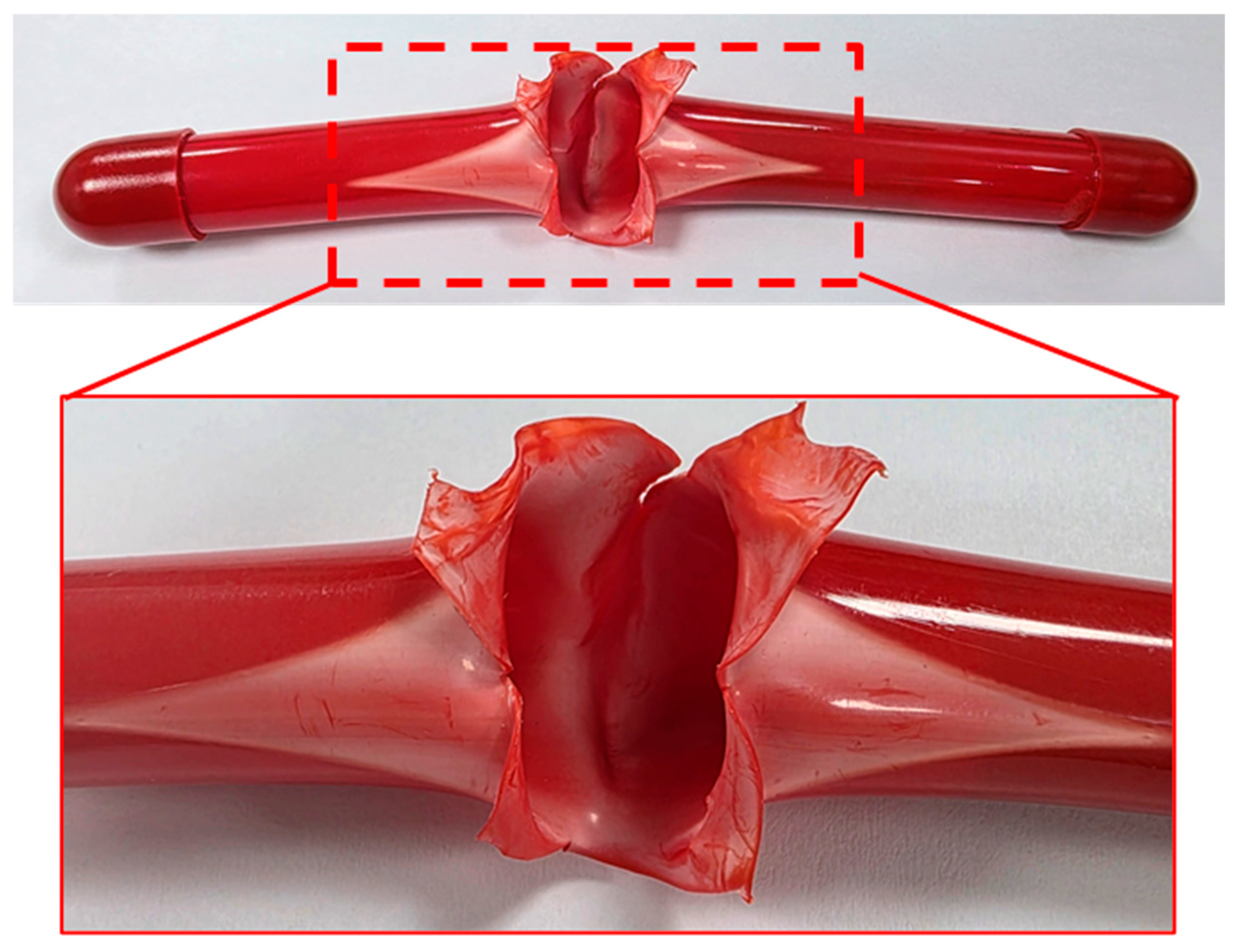
Figure 6 shows the rupture morphology observed in experimental detonation test of a thin-walled fire suppression tube. The experiment revealed that a rapid rupture occurred in the central region containing the embedded C4 charge, with cracks propagating irregularly along the tube axis. Around the ruptured area, thin-film-like fragments were observed, indicating that the explosion pressure was instantaneously concentrated in localized regions. This rupture pattern was closely related to the intrinsic properties of PA12, which was selected as the tube material in this study. Unlike metals or glass, PA12 did not produce sharp dispersive fragments upon rupture. Instead, its fracture behavior caused the tube to tear into thin membrane-like pieces without forming hazardous shrapnel. This non-dispersive fracture behavior was an important advantage, as it minimized the risk of secondary damage during detonation activation. In addition, PA12 possessed high toughness and impact resistance; therefore, even when rupture occurred, the material did not pulverize but instead formed consistent fracture surfaces. These characteristics were clearly confirmed in the experiment, where the PA12 tube exhibited localized tearing and thin-film fragments rather than brittle fragmentation, thereby supporting the rationale for selecting PA12 as the suppression tube material.
Furthermore, the rupture morphology observed in the experiment was consistent with the numerical simulation results. The simulations also predicted localized rupture near the tube center due to concentrated blast pressure. Both the experimental and numerical findings demonstrated that the structural response was governed by localized deformation around the embedded explosive. This comparison validates that the simulation model reasonably reflects the actual physical behavior and can be reliably applied to evaluate the structural performance of polymer-based suppression tubes under explosive loading.

3.2. Mesh Independence Analysis

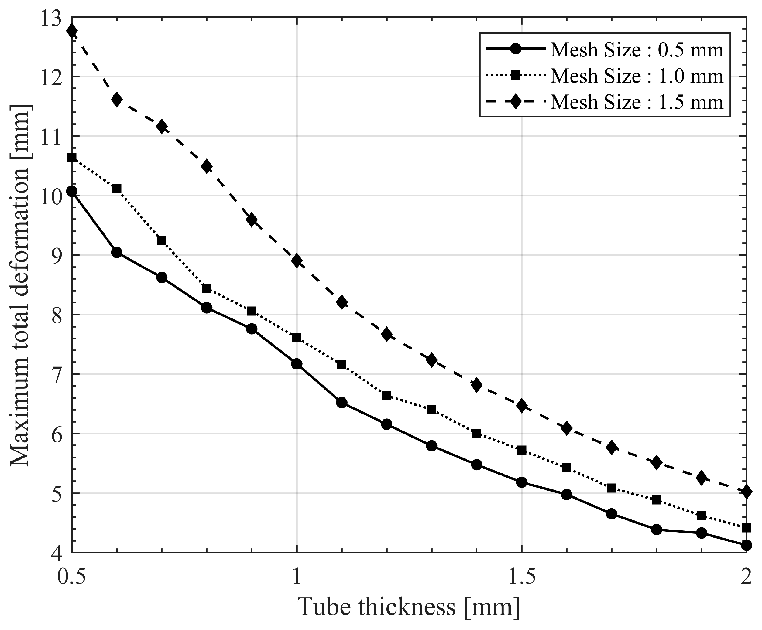
To verify numerical stability and ensure that the simulation results were not significantly affected by element size, a mesh-independence analysis was performed using element sizes of 0.5 mm, 1.0 mm, and 1.5 mm. The aluminum plate thickness was fixed at 1 mm, and all other boundary and material conditions were kept identical to those described in Section 2.3. The maximum total deformation was selected as the primary evaluation index because it directly reflects the global structural response under blast loading. The percentage difference for each mesh size was calculated relative to the 1.0 mm result, as expressed by Equation (2), which defines the relative deviation as the absolute difference between each value and the 1.0 mm reference, divided by the 1.0 mm result, and multiplied by 100 to obtain the percentage difference.
Difference   % = X X 1.0 X 1.0 × 100
As shown in Figure 7, refinement from 1.5 mm to 1.0 mm significantly reduced variation in maximum deformation, while further refinement to 0.5 mm resulted in only minor differences. Quantitatively, the average deviation between 0.5 mm and 1.0 mm meshes was approximately 7.5%, with a maximum deviation of about 10.6% near t = 0.6 mm. In contrast, the deviation between 1.0 mm and 1.5 mm meshes ranged from approximately 11% to 20%, depending on the tube thickness. Meshes finer than 1.0 mm led to a substantial increase in computation time, and attempts below 0.5 mm failed to converge due to severe element distortion during detonation.
From these observations, an element size of 1.0 mm was determined to provide the optimal balance between numerical accuracy, stability, and computational efficiency. Although finer meshes could theoretically yield more detailed stress distributions, their influence on the total deformation response was negligible. Therefore, the 1.0 mm mesh was selected for all subsequent simulations to ensure reproducible and stable results under detonation loading.

3.3. Structural Analysis Results

In this study, two primary deformation indices were obtained from the ANSYS Workbench 2024 R2 Explicit Dynamics analysis: Total Deformation and Plate Deformation. Each value was extracted as the maximum magnitude from the designated regions of the model. Minimum or average values were excluded because they do not adequately represent the severity of blast-induced deformation. By focusing on maximum responses, the analysis provides a conservative evaluation of potential structural damage under critical detonation conditions.
The Total Deformation results are presented in Figure 8, showing the global displacement distribution of the suppression tube and the adjacent aluminum plate. As the tube thickness increased from 0.5 mm to 2.0 mm, deformation became increasingly localized near the detonation center, while the overall displacement magnitude consistently decreased. This indicates that greater wall stiffness effectively restricted the propagation of blast energy and enhanced structural stability.
The results demonstrate that tube thickness is a dominant factor governing the global deformation behavior of polymer-based suppression tubes under explosive loading. The reduction in deformation followed a nonlinear trend due to the progressive increase in bending stiffness and localized confinement of detonation energy [24]. Tubes thinner than 1.0 mm exhibited flexible expansion under blast pressure, whereas thicker tubes displayed localized deformation near the initiation region. Beyond approximately 1.5 mm, additional thickening produced negligible improvement, implying that most of the detonation energy had already been absorbed locally within the tube structure [25].
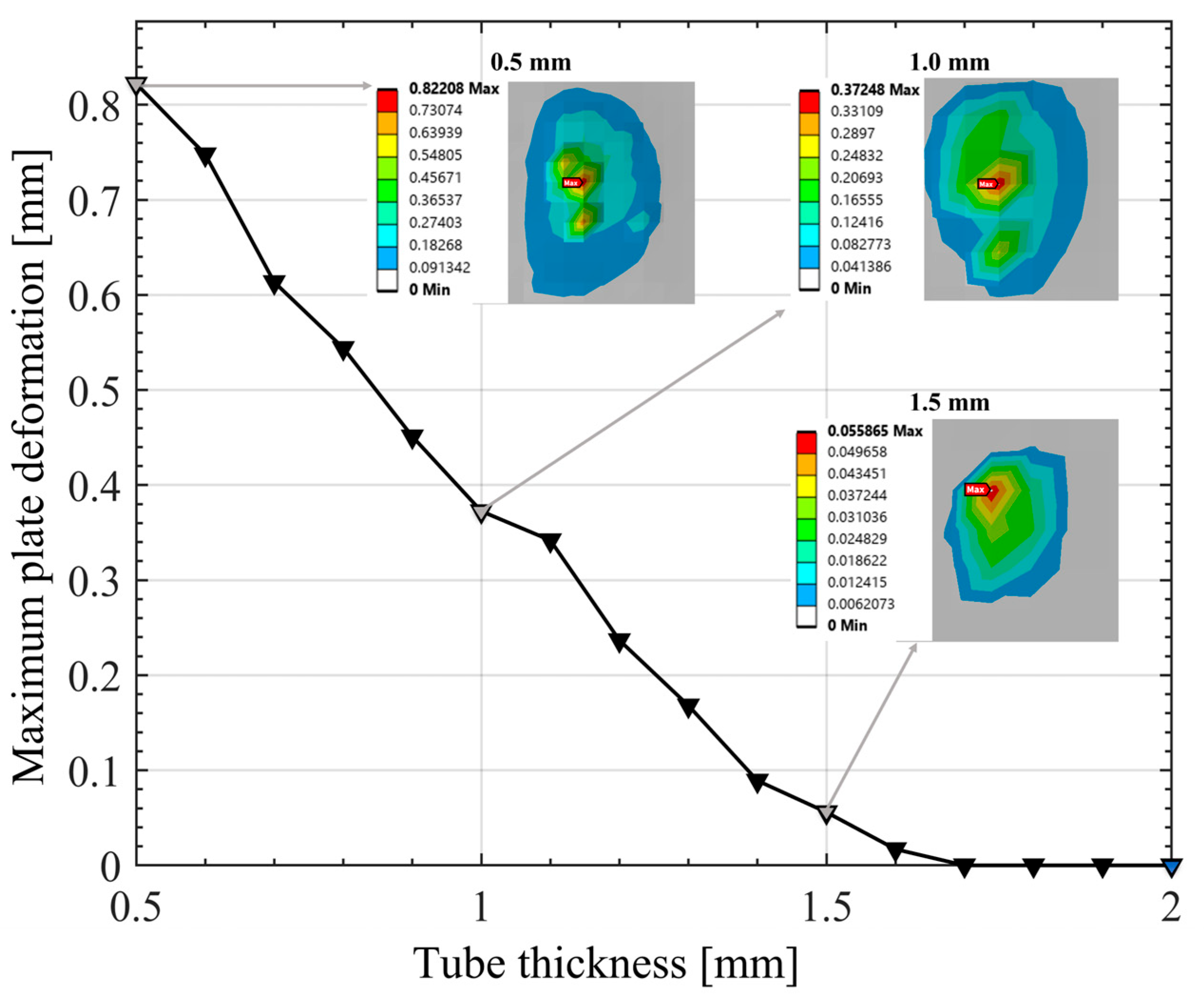
The deformation transmitted to the aluminum plate was evaluated using Plate Deformation, which quantifies the extent of detonation shock transmission from the suppression tube to the adjacent structure. As shown in Figure 9, the maximum plate deformation decreased markedly with increasing tube thickness, indicating that a thicker tube provides better structural isolation between the explosive charge and the aluminum plate. At 0.5 mm, the plate experienced pronounced localized bending due to insufficient confinement of the blast energy inside the tube. When the wall thickness increased to 1.0 mm, deformation was noticeably reduced, marking the onset of effective energy absorption. Beyond 1.5 mm, deformation became negligible, confirming that most of the detonation energy was dissipated within the tube rather than being transmitted to the plate [26].
The embedded deformation contours in Figure 9 visualize this trend, showing that the deformation zone shrinks and the strain intensity decreases as the tube wall thickens. This nonlinear decrease in plate deformation demonstrates that tube stiffness plays a dominant role in controlling blast–energy transmission, validating the protective effectiveness of thicker polymer tubes in isolating adjacent structures from detonation impacts.

3.4. Effect of Material Density on Deformation Behavior

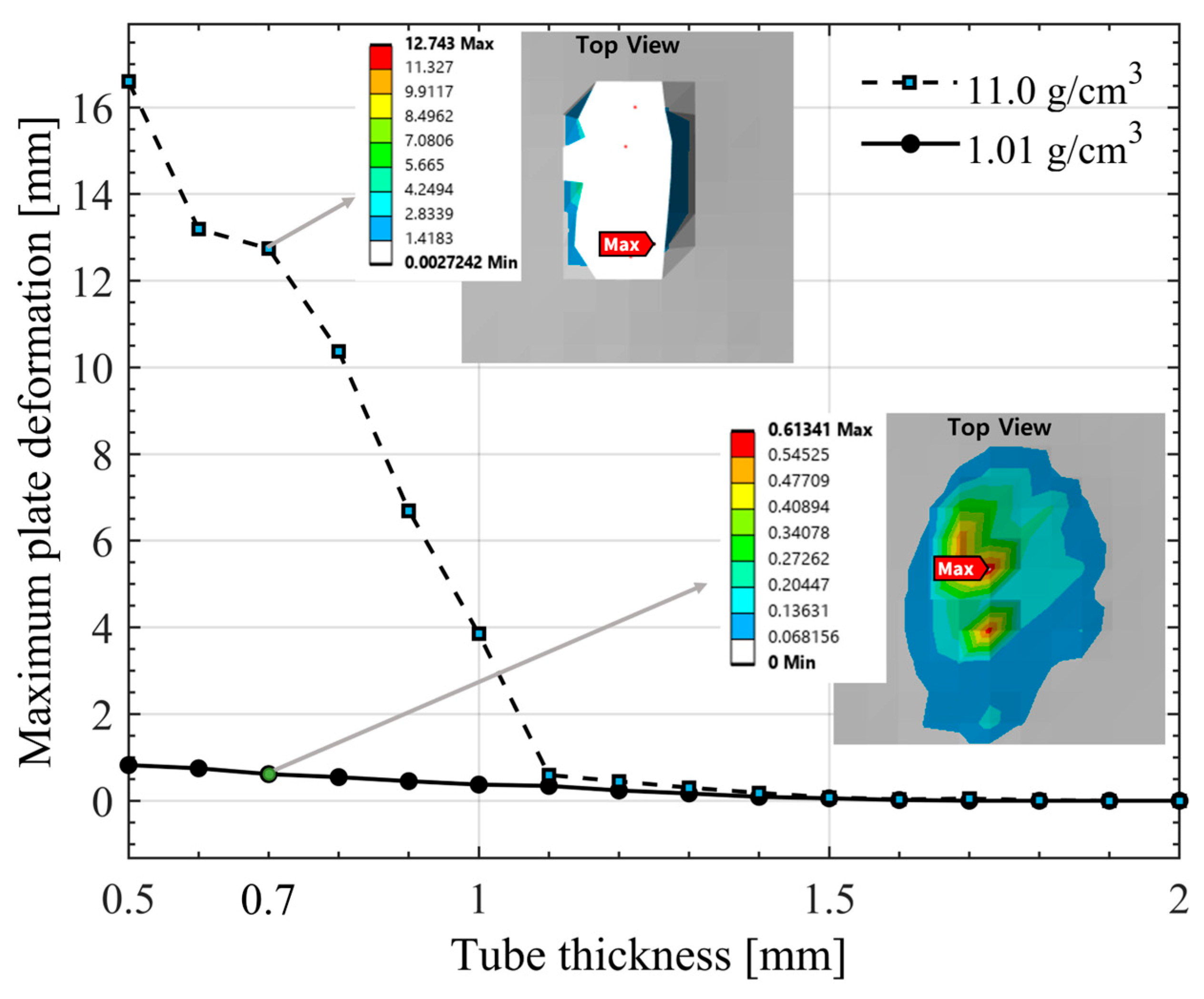
To evaluate the influence of material density on the deformation transmitted to adjacent structures, a sensitivity analysis was performed for PA12-based suppression tubes with densities of 1.01 g/cm3 and 11.0 g/cm3. The higher value was selected as an upper reference based on the extended range reported in certain polymer material databases. All other boundary and material conditions were kept identical to those described in Section 2.3.
As shown in Figure 10, increasing material density significantly amplified the plate deformation under detonation loading. For the nominal-density model (1.01 g/cm3), the aluminum plate exhibited only minor bending, with a peak deformation of approximately 1 mm at tube thicknesses below 1.0 mm. However, for the high-density model (11.0 g/cm3), the corresponding deformation values were approximately 10–20 times larger, equivalent to +933% to +1919% higher than those of the nominal-density case within the same thickness range. This pronounced difference indicates that higher density results in greater inertial resistance and acoustic impedance, leading to stronger energy transmission from the tube to the plate.
Once the tube thickness exceeded 1.1 mm, both density models converged to nearly identical deformation magnitudes, indicating that the density effect becomes negligible when sufficient tube stiffness is achieved. Consequently, density mainly influences the absolute magnitude of transmitted deformation rather than altering the overall attenuation trend governed by structural stiffness.
In summary, material density acts as a secondary factor affecting the structural response under explosive loading. While a higher-density tube enhances momentum transfer and impact transmission, a lower-density tube improves energy absorption and isolation performance, providing more favorable protection for adjacent components.

4. Conclusions

This study performed explicit dynamics simulations to evaluate the structural responses of a C4-actuated polymer-based fire suppression tube designed for electric vehicle (EV) battery protection. Two primary deformation indices—total deformation and plate deformation—were analyzed while varying tube thickness from 0.5 mm to 2.0 mm.
The results revealed that thinner tubes (≤1.0 mm) allowed detonation shock to propagate throughout the structure, leading to extensive global bending and larger deformation of the adjacent aluminum plate. As tube thickness increased, deformation became localized near the detonation region and the transmitted shock decreased markedly. When the thickness exceeded 1.5 mm, plate deformation converged to nearly zero, indicating that most of the blast energy was confined within the tube. Therefore, a minimum thickness of 1.5 mm is proposed as a practical design criterion for ensuring structural safety and minimizing secondary damage to surrounding components.
A density sensitivity analysis further confirmed that higher material density amplifies the magnitude of transmitted deformation in thin walls due to increased acoustic impedance, whereas lower density improves energy absorption and structural isolation. These findings demonstrate that tube stiffness governs the primary shock attenuation mechanism, while material density serves as a secondary factor affecting energy transmission.
Overall, this study provides quantitative design guidelines for polymer-based automatic fire suppression tubes. Maintaining a wall thickness ≥ 1.5 mm ensures effective confinement of detonation energy and reliable protection of EV battery modules. Future work may include experimental validation under practical module conditions, as well as extended studies on temperature-dependent and composite materials, which could contribute to establishing comprehensive design standards for next-generation battery module suppression systems.

Author Contributions

Conceptualization, M.-S.K., T.-W.Y. and S.-U.Z.; methodology, T.-W.Y.; software, T.-W.Y. and S.-U.Z. (ANSYS Workbench 2024 R2); validation, M.-S.K., T.-W.Y. and S.-U.Z.; formal analysis, T.-W.Y.; investigation, M.-S.K. and T.-W.Y.; resources, T.-W.Y. and S.-U.Z.; data curation, T.-W.Y.; writing—original draft preparation, M.-S.K. and T.-W.Y.; writing—review and editing, M.-S.K. and T.-W.Y.; visualization, T.-W.Y.; supervision, M.-S.K. and S.-U.Z.; project administration, M.-S.K. and S.-U.Z.; funding acquisition, M.-S.K. All authors have read and agreed to the published version of the manuscript.

Funding

This research received no external funding.

Institutional Review Board Statement

Not applicable.

Informed Consent Statement

Not applicable.

Data Availability Statement

The original contributions presented in this study are included in the article. Further inquiries can be directed to the corresponding author.

Conflicts of Interest

The authors declare no conflicts of interest. The funders had no role in the design of the study; in the collection, analyses, or interpretation of data; in the writing of the manuscript; or in the decision to publish the results.

References

  1. Sun, P.; Bisschop, R.; Niu, H.; Huang, X. A Review of Battery Fires in Electric Vehicles. Fire Technol. 2020, 56, 1361–1410. [Google Scholar] [CrossRef]
  2. Fire Safety Research Institute (FSRI). Fire Safety of Batteries and Electric Vehicles; UL Research Institutes Report: Northbrook, IL, USA, 2023. [Google Scholar]
  3. Tarascon, J.M.; Armand, M. Issues and Challenges Facing Rechargeable Lithium Batteries. Nature 2001, 414, 359–367. [Google Scholar] [CrossRef]
  4. Goodenough, J.B.; Park, K.-S. The Li-Ion Rechargeable Battery: A Perspective. J. Am. Chem. Soc. 2013, 135, 1167–1176. [Google Scholar] [CrossRef] [PubMed]
  5. Goodenough, J.B.; Kim, Y.-S. Challenges for Rechargeable Li Batteries. Chem. Mater. 2010, 22, 587–603. [Google Scholar] [CrossRef]
  6. Armand, M.; Tarascon, J.M. Building Better Batteries. Nature 2008, 451, 652–657. [Google Scholar] [CrossRef]
  7. Finegan, D.P.; Scheel, M.; Robinson, J.B.; Tjaden, B.; Hunt, I.; Mason, T.J.; Millichamp, J.; DiMichiel, M.; Offer, G.J.; Hinds, G.; et al. In-Operando High-Speed Tomography of Lithium-Ion Batteries during Thermal Runaway. Nat. Commun. 2015, 6, 6924. [Google Scholar] [CrossRef] [PubMed]
  8. Wang, H.; Shi, W.; Hu, F.; Wang, Y.; Hu, X.; Li, H. Over-Heating Triggered Thermal Runaway Behavior for Lithium-Ion Battery with High Nickel Content in Positive Electrode. Energy 2021, 224, 120072. [Google Scholar] [CrossRef]
  9. Rask, E.; Stutenberg, K.; Waller, T. Li-Ion Battery Pack Immersion Exploratory Investigation; Report No. DOT HS 813 136; United States Department of Transportation, National Highway Traffic Safety Administration: Washington, DC, USA, 2021. [Google Scholar] [CrossRef]
  10. Ineris. Summary of Work on Extinguishing Li-Ion Battery Fires of Electric Vehicles; Ineris Report: Verneuil-en-Halatte, France, 2023. [Google Scholar]
  11. Hong, J.; Wang, Z.; Zhang, X.; Wang, W.; Chen, Y.J.; Shan, T. Collision-Caused Thermal Runaway Investigation of Li-Ion Battery in Real-World Electric Vehicles. Appl. Therm. Eng. 2024, 236, 121901. [Google Scholar] [CrossRef]
  12. Lee, B.J.; Choi, G.J.; Lee, S.H.; Jeong, Y.M.; Park, Y.; Cho, D.U. A Study on Explosion and Fire Risk of Lithium-Ion and Lithium-Polymer Battery. J. Korean Inst. Commun. Inf. Sci. 2017, 42, 855–863. [Google Scholar] [CrossRef]
  13. Li, Z.; Wang, Q. Experimental Study of Explosive Water Mist Extinguishing Fire. Procedia Eng. 2011, 11, 258–267. [Google Scholar] [CrossRef]
  14. Li, H.J.; Shen, C.J.; Lu, G.; Wang, Z.H. Response of Cylindrical Tubes Subjected to Internal Blast Loading. Eng. Struct. 2022, 272, 115004. [Google Scholar] [CrossRef]
  15. Aune, V.; Valsamos, G.; Casadei, F.; Langseth, M.; Børvik, T. On the Dynamic Response of Blast-Loaded Steel Plates with and without Pre-Formed Holes. Int. J. Impact Eng. 2017, 108, 27–46. [Google Scholar] [CrossRef]
  16. Sakong, J.; Woo, S.C.; Bae, Y.W.; Choi, Y.J.; Cha, J.P.; Ga, I.H.; Kim, T.W. Dispersion Pattern Simulation of Tungsten Impactors According to Mass and Shape of Explosives. J. Korean Soc. Mech. Eng. A 2014, 38, 1325–1333. [Google Scholar] [CrossRef]
  17. Kuracina, R.; Szabová, Z.; Buranská, E.; Kosár, L.; Rantuch, P.; Blinová, L.; Měřínská, D.; Gogola, P.; Jurina, F. Study into the fire and explosion characteristics of polymer powders used in engineering production technologies. Polymers 2023, 15, 4203. [Google Scholar] [CrossRef]
  18. Hegde, G.; Verma, H.; Hegde, G.; Jagadeesh, G.; Asokan, S. Blast wave induced strain measurements in polymers using FBG sensor inside shock tube. Measurement 2024, 225, 114045. [Google Scholar] [CrossRef]
  19. Radermacher, L.; Mateescu, T. Study on the Behaviour of High-Density Polyethylene (HDPE) Pipes Buried, on the Explosion’s Effect. In Proceedings of the International Conference Building Services and Energy Efficiency, London, UK, 26–27 October 2020; pp. 268–275. [Google Scholar] [CrossRef]
  20. Michael, L.; Nikiforakis, N. A multi–physics methodology for the simulation of reactive flow and elastoplastic structural response. J. Comput. Phys. 2018, 367, 1–27. [Google Scholar] [CrossRef]
  21. Gu, M.; Wang, H.; Chen, G.; Yu, A.; Dang, W.; Ling, X. Experimental and numerical study on explosion resistance of polyurea-coated shelter in petrochemical industry. Sci. Rep. 2024, 14, 20643. [Google Scholar] [CrossRef] [PubMed]
  22. Nam, S.H.; Kim, J.Y.; Kim, E.S. Crash Safety Evaluation of LNG Fuel Containers for Vehicles Using ANSYS Explicit Dynamics. J. Korean Inst. Gas 2022, 26, 58–63. [Google Scholar] [CrossRef]
  23. Zhang, S.; Wang, X.; Zhang, Q.; Bai, Z.; Cao, X. Numerical study on explosion risk and building structure dynamics of long-distance oil and gas tunnels. Fire 2024, 7, 302. [Google Scholar] [CrossRef]
  24. Kong, W.; Yang, S.; Wang, S.; Liu, Z.; Zhang, R.; Zhong, W.; Yao, X. On dynamic response and damage evaluation of bridge piers under far-field explosion loads. Structures 2023, 54, 1044–1059. [Google Scholar] [CrossRef]
  25. Wang, S.; Li, Z.; Fang, Q.; Yan, H.; Liu, Y. Numerical simulation of overpressure loads generated by gas explosions in utility tunnels. Process Saf. Environ. Prot. 2022, 161, 100–117. [Google Scholar] [CrossRef]
  26. Jeong, W.S.; Pyeon, Y.B. A Study on Analysis of Explosion Damage Reduction Effect on Protective Wall for Hydrogen Production Base via Explosion Simulation. J. Korea Soc. Nav. Sci. Technol. 2025, 8, 88–95. [Google Scholar] [CrossRef]
Figure 1. Workflow of the simulation procedure, outlining the explosion scenario definition, model components, material assignment, simulation setup, and key output metrics.
Applsci 15 11718 g001
Figure 2. Fire suppression tube in its original state.
Applsci 15 11718 g002
Figure 3. Simulation model of the fire suppression tube with C4 and Aluminum Plate.
Applsci 15 11718 g003
Figure 4. Schematic diagram of suppression tube showing key geometric parameters (length, inner diameter, and gap).
Applsci 15 11718 g004
Figure 5. Detonation point setting applied to C4 explosive (the box indicates the location of the detonation point).
Applsci 15 11718 g005
Figure 6. Actual rupture of fire suppression tube after C4 activation.
Applsci 15 11718 g006
Figure 7. Comparison of maximum total deformation for mesh sizes of 0.5 mm, 1.0 mm, and 1.5 mm, demonstrating convergence and stability at 1.0 mm.
Applsci 15 11718 g007
Figure 8. Total deformation results at varying tube thicknesses (0.5–2.0 mm).
Applsci 15 11718 g008
Figure 9. Maximum plate deformation as a function of tube thickness for the PA12 suppression tube.
Applsci 15 11718 g009
Figure 10. Maximum plate deformation as a function of tube thickness for PA12-based suppression tubes with different material densities (1.01 and 11.0 g/cm3).
Applsci 15 11718 g010
Table 1. Properties of PA12.
DensityYoung’s ModulusPoisson’s Ratio
1.01 [g/cm3]881 [MPa]0.4
Table 2. Jones–Wilkins–Lee parameters for C4.
ParameterValueParameterValue
P28 [GPa]E5621 [kJ/m3]
A609.77 [GPa]R14.5
B12.95 [GPa]R21.4
Cd8193 [m/s]ω0.25
C4 Mass0.07685 [g]
Table 3. Material properties of the Aluminum Plate (Aluminum Alloy NL).
Density Specific HeatTemperature
2.77 [g/cm3]875 [J/kg·C]22 [°C]
Disclaimer/Publisher’s Note: The statements, opinions and data contained in all publications are solely those of the individual author(s) and contributor(s) and not of MDPI and/or the editor(s). MDPI and/or the editor(s) disclaim responsibility for any injury to people or property resulting from any ideas, methods, instructions or products referred to in the content.