Article

Research on Crack Propagation in Hard Rock Coal via Hydraulic Fracturing

1
School of Mining, Liaoning Technical University, Fuxin 123000, China
2
School of Mechanical Engineering, Liaoning Technical University, Fuxin 123000, China
3
Fujinson (Nantong) Technology Co., Ltd., Nantong 226019, China
*
Author to whom correspondence should be addressed.
Appl. Sci. 2025, 15(21), 11696; https://doi.org/10.3390/app152111696 (registering DOI)
Submission received: 26 September 2025 / Revised: 27 October 2025 / Accepted: 28 October 2025 / Published: 1 November 2025

Abstract

Hydraulic fracturing is a technique employed to weaken rock formations during hard rock excavation. This study aims to investigate the impact of hydraulic fracturing on crack propagation in rock walls and its subsequent effect on the load borne by roadheaders during the cutting of pre-cracked rock. A three-dimensional model for the crack growth process in rock walls under hydraulic fracturing is developed using the CFD-DEM (Computational Fluid Dynamics–Discrete Element Method) two-way fluid–structure coupling approach. The results indicate that crack propagation under hydraulic fracturing occurs in four distinct phases: the initiation of the main crack, the further development of the main crack, the fine cracking phase, and the retardation of the main crack with the subsequent expansion of secondary cracks. The study analyzes the influence of pore size and water injection pressure on crack growth. It is observed that an increase in pore size and injection pressure within a certain range results in a nonlinear increase in crack propagation. Specifically, when the hydraulic fracturing aperture expands from 85 mm to 100 mm, the number of fracture bonds increases by 56.2%. Similarly, as water injection pressure rises from 25 MPa to 40 MPa, the number of broken bonds increases by 153.9%. The force exerted on rock with pre-existing cracks is found to be 9.05% lower compared to unfractured rock, with the average forces in the Z and Y directions reduced by 11.46% and 7.2%, respectively. However, the average force in the X direction increases by 5.49%. These findings provide a valuable reference for optimizing hydraulic fracturing procedures in hard rock excavation.

1. Introduction

In modern mining engineering, fracture-assisted rock-breaking techniques are commonly utilized to enhance the efficiency of hard rock excavation. Additionally, these methods improve coal seam permeability and mitigate the risk of coal and gas outbursts [1,2,3,4]. Initially applied in high-gas coal mines, coal and rock fragmentation technologies have progressively found applications in coal mining, particularly in the weakening and control of hard top coal and coal discharge at the ends of fully mechanized caving faces.
Due to the complex and often concealed nature of hydraulic fracturing processes, numerical analysis has become a widely used approach for understanding these mechanisms. This includes methods such as Finite Element Method (FEM), Extended Finite Element Method (XFEM), Synthetic Rock Mass (SRM) modeling, and Discrete Element Method (DEM). Noteworthy contributions to two-dimensional hydraulic fracturing research in coal mining include studies by Heider Y [5], who applied the Particle Flow Method (PFM) to create a 2D fracturing model and proposed techniques for estimating fracture aperture widths. Zhang Yulong [6] developed a hydro-mechanical model based on the PFC2D particle flow approach to effectively model fluid flow through porous rock matrices, examining the relationships between confining pressure, injection rate, fluid viscosity, and crack propagation. Chong Zhaohui [7,8] investigated the effects of stress differences, friction coefficients, and approach angles on structural seismic resistance, identifying four distinct interaction modes between natural and artificial fractures.
In the realm of three-dimensional hydraulic fracturing, studies by Kang Hongpu [9] employed the XSite 3D hydraulic fracturing simulation software to model fracturing in composite rock layers, concluding that a higher elastic modulus, reduced fracture toughness, and lower horizontal stress enhance the propagation of hydraulic fractures. Zhao Kaikai [10,11] developed a 3D fracture propagation model based on synthetic rock mass methods and discrete lattice theory, demonstrating that hydraulic fracturing generates cracks and diminishes the strength of rock masses [12,13].
However, current theoretical models and numerical simulations of hydraulic fracturing for tunnel excavation using DEM often overlook fluid flow within fractures. These models typically assume constant internal pressure and neglect the hydro-mechanical coupling effects on fracture propagation. Furthermore, the impact of pre-fractured rock walls on the performance of tunnel boring machine cutting picks remains underexplored. This study applies the CFD-DEM bidirectional fluid–structure coupling method to simulate the behavior of rock walls under varying borehole diameters and injection pressures, aiming to elucidate the mechanisms of crack propagation and the load variations on cutting picks under different influencing factors. The results provide valuable insights for optimizing excavation parameters in hard rock scenarios post-hydraulic fracturing, offering practical guidance for industrial applications.

2. Materials and Methods

2.1. Discrete Element Method (DEM)

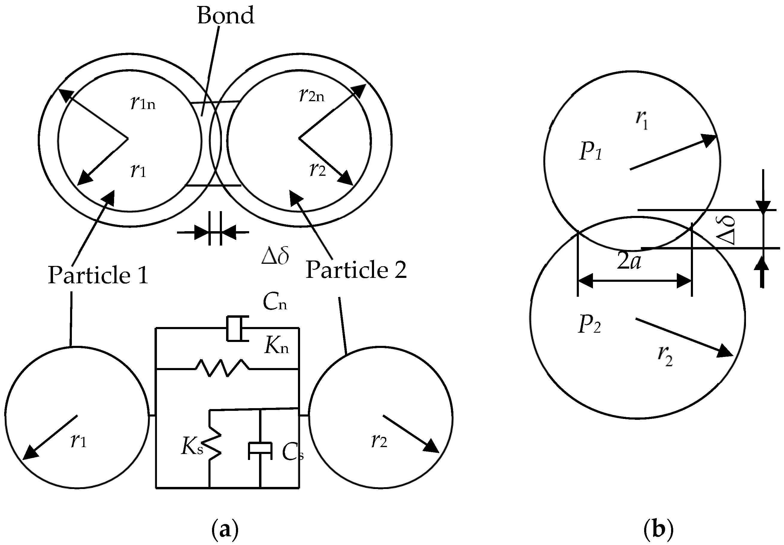
The Discrete Element Method (DEM), which has its origins in molecular dynamics, is primarily concerned with investigating the mechanical properties and behaviors of discontinuous media [14]. It has proven to be an effective tool for simulating the propagation of rock fractures [15]. In practical fracturing processes, phenomena such as electrical or thermal interactions between rock particles and fracturing mechanisms are typically absent, and adhesive effects are disregarded. Consequently, the parallel bond model, coupled with the Hertz-Mindlin (no-slip) contact model (henceforth referred to as the H-M model), is employed, as shown in Figure 1. The parallel bond model is adept at simulating both the initiation of fractures and subsequent crack propagation. When bonded rock particles are subjected to stresses that exceed the bond strength during hydraulic pre-fracturing, the bonds fail, leading to crack initiation and propagation.
The parallel bond model [16] effectively captures the influence of microstructural characteristics on the macroscopic behavior of the material. Given the constraints on particle shape and size, voids inevitably form during particle packing, which can be leveraged to simulate natural fractures within the rock matrix. These microcracks interact and ultimately coalesce, forming macroscopic fractures. Under the application of fracturing or cutting forces, the bonds between particles break when the applied stress exceeds the cohesive strength of the bonds, resulting in the formation of cracks. The mechanical interactions are governed by the H-M contact model, with the failure criterion defined by Equation (1):
σ max < F n A + 2 T t J R τ max < F t A + T n J R
where A = πR2, A is the contact area, mm2, J = 1 2 π R 4 , J is the moment of inertia, mm4, R = R A R B , R particle bonding radius, mm, RA, RB is Ball A, B particle radius, mm, Fn, Ft is Normal and tangential forces, N, Tn, Tt is Normal and tangential moments, N∙m.
The displacement and velocity of discrete phase particles within a flow field can be determined using Newtonian mechanics by resolving inter-particle collisions and the hydrodynamic forces acting on the particles [17,18]. The governing equations of motion for the discrete phase are expressed as:
m i d v i d t = j F n , j i + F τ , j i + F f p , i + m i g d d t I i ω i = j r i × F τ , j i + M i
where mi is the particle mass, kg, vi is the particle velocity, m/s, Fn,ji and Fτ,ji are the normal and tangential contact forces between particles in the fluid domain, N, Ffp,i is the force exerted by the continuous phase on the particle, N, Ii is the particle moment of inertia, kg∙m2, ωi is the angular velocity of the particle in the fluid domain, rad/s, γi is the particle radius within the fluid domain, mm, Mi is the rolling friction torque acting on the particle, N∙m, t is time, s, and g is the gravitational acceleration, m/s2.
The fluid-solid coupling in hydraulic fracturing, when using the Discrete Element Method (DEM), is predominantly governed by particle flow theory, which also forms the foundation for bidirectional coupling between Fluent and EDEM [19]. In particle flow theory, the fundamental building blocks of the model consist of discrete, mass-bearing particles in motion [20,21]. This method efficiently simulates crack initiation and propagation, making it particularly well-suited for investigating the mechanisms of crack extension during hydraulic fracturing in coal masses [22].

2.2. Coupled Model Establishment

Prior to conducting particle flow simulations, the physico-mechanical properties of the coal-rock samples were experimentally characterized [23]. Hard rock specimens from the 2706 Lower Working Face of Layer 17 coal at Yangcun Mine, Yankuang Group, were processed using a DQ-1 cutting machine (Tianjin Sishu Testing Instru-ment Manufacturing Co., Ltd., Tianjin, China) to obtain standardized samples. The bulk density of the rock was calculated to be 2600 kg/m3 based on mass-to-volume measurements. Uniaxial compression tests, performed using a WDW-100E (Wuyi Hengyu Instrument Co., Ltd., Dongguan, China) testing machine, determined the compressive strength to be 71 MPa, derived from the peak failure force divided by the contact area. Subsequently, the samples were crushed in a pulverizing chamber, sieved, and analyzed using a measuring cylinder and piston gauge (Wuxi Endi Measuring Instrument Technology Co., Ltd., Wuxi, China) to determine the Protodyakonov strength coefficient (f-value), which was found to be 8.4.
In EDEM, a rock wall model with dimensions of 500 mm × 500 mm × 500 mm was constructed under unconfined conditions. This model consisted of 111,244 spherical particles, each with a nominal radius of 5 mm [13], and featured a randomized uniform particle size distribution, scaled between 0.8× and 1.2× the base radius. Key particle parameters [24,25], including contact stiffness, friction coefficients, and bond strengths, are summarized in Table 1.
Hard rock structures generally exhibit high integrity, characterized by significant tensile, compressive, and shear strengths, with minimal deformation under external loading conditions [26]. In the discrete element model, a rock wall incorporating pre-existing fractures (pre-cracks) was created, as depicted in Figure 2a.
To streamline the numerical simulations, non-essential fluid domains, such as the injection boreholes, were either simplified or removed from the Fluent model. The remaining fluid domain was discretized into a structured mesh. To ensure compatibility between EDEM and Fluent during coupled simulations, the particle diameter in EDEM must be at least one-third of the minimum grid cell size in Fluent [27]. With a maximum particle diameter of 12 mm, the minimum grid cell size was determined to be 5 cm. The structured mesh configuration is shown in Figure 2b.

2.3. Simulation Parameters

In Fluent, the multiphase flow was modeled using the Dense Discrete Phase Model (DDPM). The materials were defined as air and liquid water. The inner surface of the pre-existing borehole was configured as a pressure inlet, while the surrounding surfaces were set as vent outlets to minimize air interference during the fracturing simulations. All other boundaries were defined as no-slip walls. The external fluid domain was initialized with air, while the borehole was initialized with liquid water, maintaining a stress ratio of 1 in all directions.

3. Simulation Results and Analysis

3.1. Crack Propagation Evolution and Cutting Pick Load Study

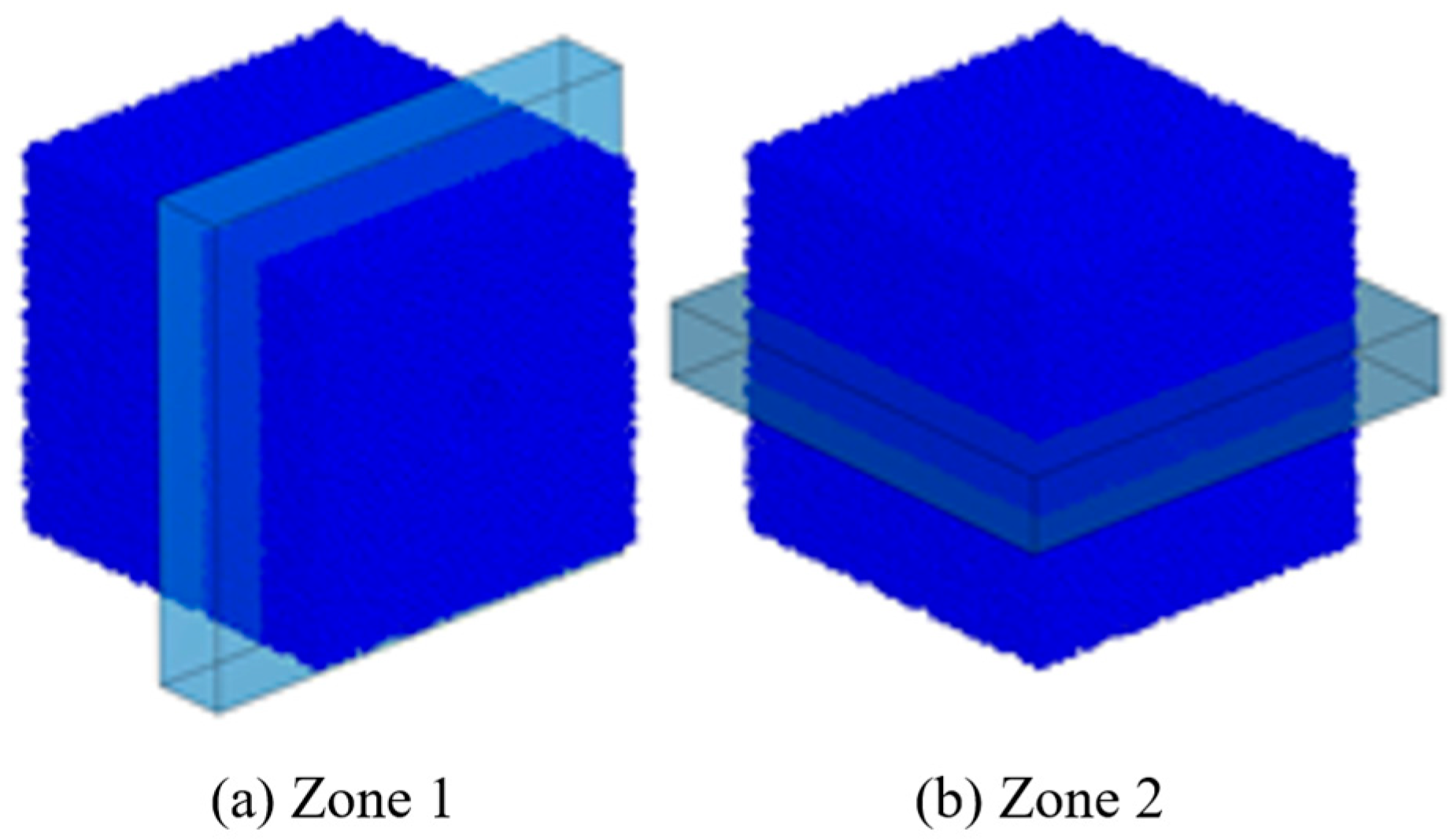
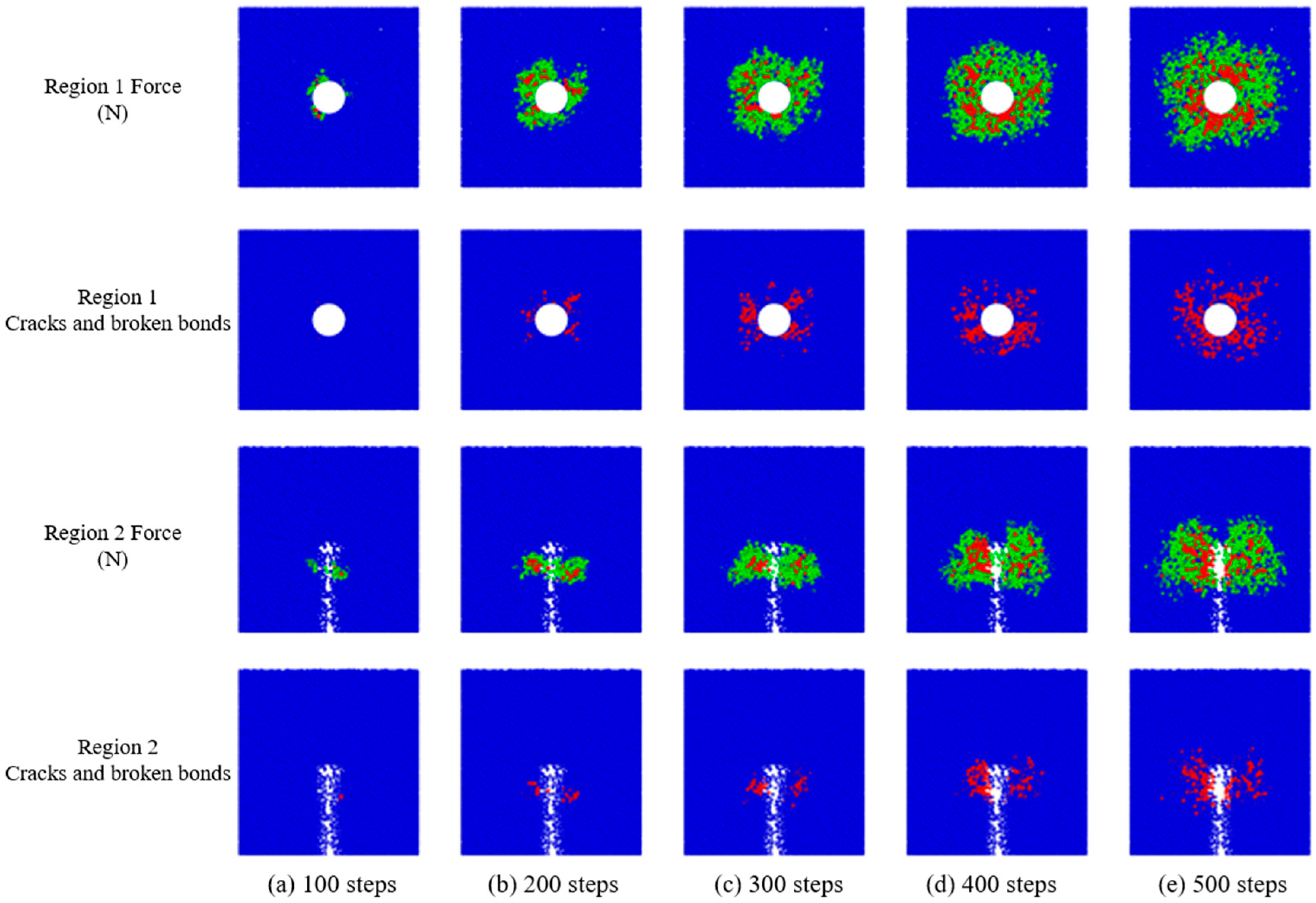
To observe the pre-fracturing of the rock wall during hydraulic injection, two distinct observation regions were defined: Region 1 (vertical cross-sectional plane) and Region 2 (horizontal cross-sectional plane), as illustrated in Figure 3. Simulations were conducted under the following conditions: an injection pressure of 30 MPa, a borehole diameter of 90 mm, a borehole depth of 250 mm, a Protodyakonov strength coefficient (f-value) of 8, and an isotropic stress ratio of 1:1:1. The temporal evolution of rock wall parameters during the injection of fracturing fluid is depicted in Figure 4. For better visualization of bond failures, the particles were rendered semi-transparent.
According to the discrete element bonded particle model theory, hydraulic pressure induces internal cracking in the rock through the rupture of interparticle bonds [28]. As shown in Figure 4a, when the borehole pressure exceeds the parallel bond normal maximum stress, localized damage initiates near the injection point [29]. This damage is characterized by sporadic bond failures within a confined region. Figure 4b reveals that prolonged fracturing under sustained pressure generates five primary cracks. As fracturing progresses (Figure 4c), these primary cracks elongate, and limited microcracks begin to nucleate. By Figure 4d, the growth of primary cracks decelerates, and secondary cracks begin to emerge, marking the onset of crack branching. At Step 500 (Figure 4e), secondary cracks continue to propagate, significantly expanding the pre-fractured zone.
The EBZ200 roadheader’s cutting picks were integrated into EDEM [30], with their contact coefficients, kinematic parameters (such as rotational speed and cutting trajectory), and material properties defined as outlined in Table 2. The cutting simulation utilized a time step of 1 × 10⁻⁶ s, a total duration of 0.1 s, and a data saving interval of 0.001 s.
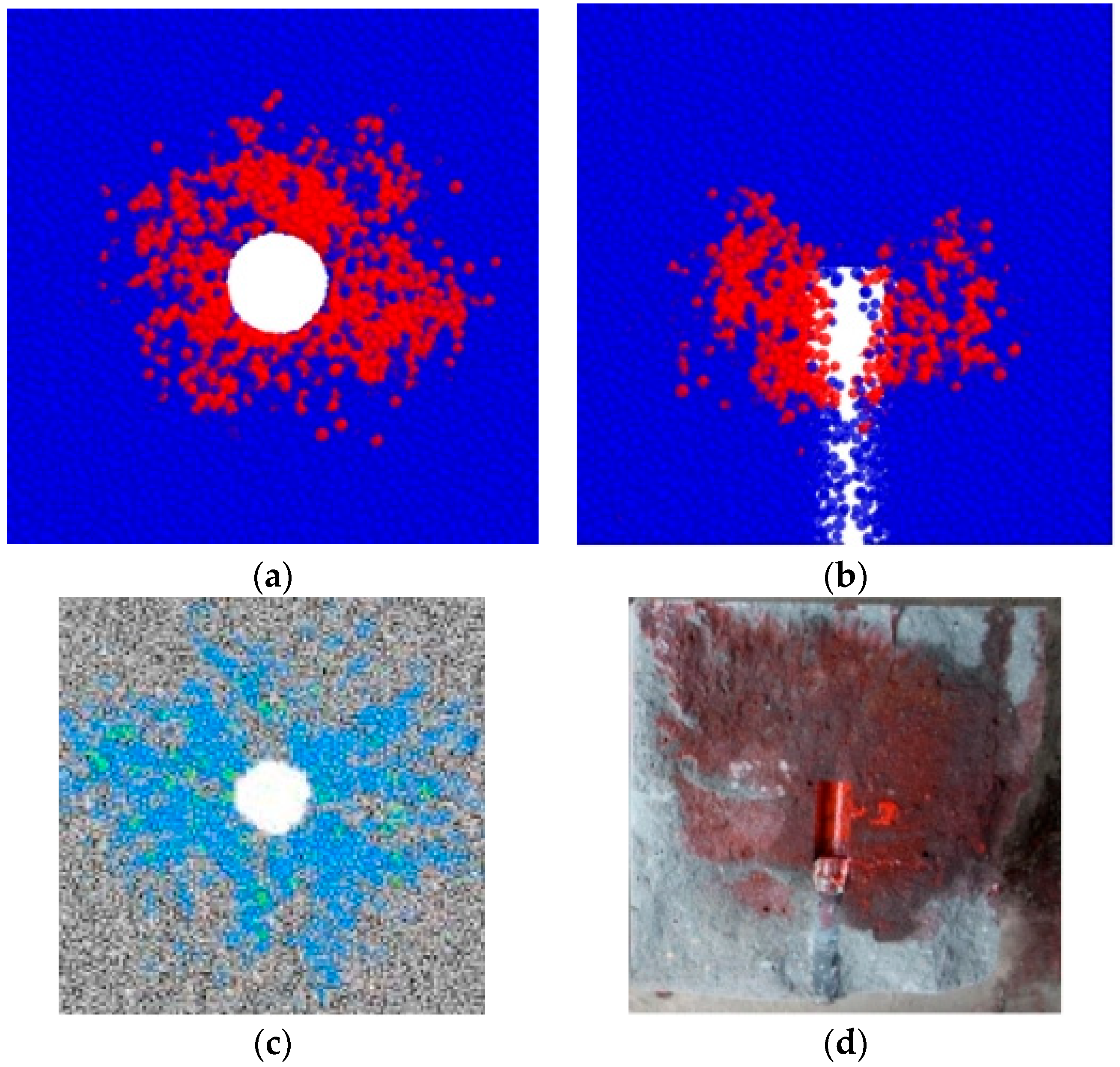
In Figure 5, consistent with both laboratory and numerical hydraulic fracturing studies reported in the literature [28], as the internal pressure of the borehole increases, the stresses exerted on the particles surrounding the borehole wall progressively intensify, leading to the initiation of cracks around the interior wall of the borehole. As pressure continues to rise, additional cracks form within the model, and four principal fractures emerge in opposite directions, intersecting at the borehole center. This behavior aligns with the findings presented in Reference [11].
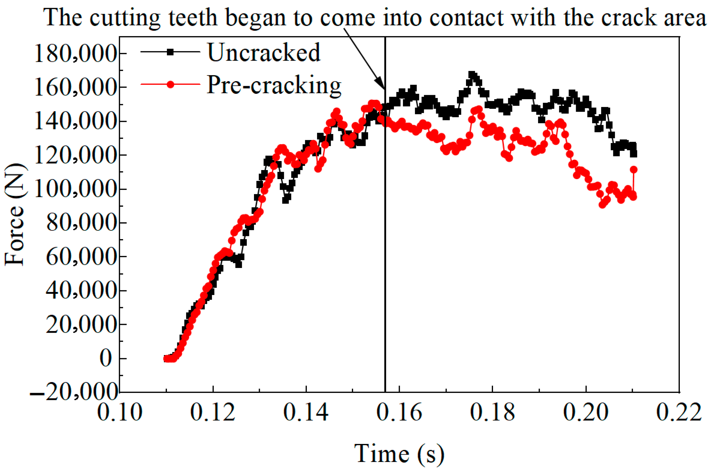
Upon completion of the simulation, the forces acting on the rock are illustrated in Figure 6. As shown, the cutting pick begins to engage with the rock wall between 0.1 s and 0.15 s. During this period, the loads on both the pre-fractured and non-fractured rock walls exhibit an upward trend. Starting at 0.15 s, the cutting pick fully penetrates the rock wall and transitions into the pre-fractured zone, eventually reaching the crack termination region. To isolate the influence of pre-fractured boreholes on cutting loads, the pick exclusively cuts the rock surrounding the pre-fractured holes, rather than the holes themselves. The mean load on pre-fractured rock was 111,660 N, which is lower than the mean load on un-prefractured rock (122,780 N), corresponding to a reduction of 9.05%. The peak load on a pick cutting pre-fractured rock was 150,780.7 N, compared with 167,789.8 N for the un-prefractured case. This reduction in peak force is primarily attributable to the presence of pre-existing fractures, which reduce the mechanical resistance of the rock and thus the cutting force required.
The time-dependent variation curves of triaxial forces are shown in Figure 7. As the cutting pick penetrates the rock wall, the triaxial stresses gradually increase, with the force in the Z-direction exhibiting the highest magnitude. Post-fracturing, the average Z-direction force decreases to −93,973 N (compared to −106,140 N for non-fractured rock), representing an 11.46% reduction. However, the load fluctuation coefficient increases slightly from 0.0017 (non-fractured) to 0.0018 (post-fractured). For the Y-direction, the average force decreases by 7.2% (from −50,188 N to −46,574 N), while the fluctuation coefficient rises from 0.0031 to 0.0033. In contrast, the X-direction displays an increase in average force by 5.49% (from 29,001 N to 30,592 N), accompanied by a decrease in the fluctuation coefficient from 0.0047 to 0.0041.

3.2. Influence of Hydraulic Fracturing Borehole Diameter

Based on the diameter of the mining drill bit used in roadway hydraulic fracturing for coal discharge, pre-fracturing borehole diameters of 85 mm, 90 mm, 95 mm, and 100 mm were tested under a constant water injection pressure of 30 MPa. Crack propagation and bond breakage under varying borehole diameters are illustrated in Figure 8. A comparative analysis of the four scenarios reveals that cracks primarily radiate outward around the borehole and propagate radially. As depicted in Figure 8, crack propagation becomes more extensive as the borehole diameter increases from 85 mm to 100 mm. At 85 mm, the smallest borehole diameter, crack initiation is slower, development is less pronounced, and the fracturing radius is minimal, resulting in suboptimal pre-fracturing effectiveness. As the diameter increases to 100 mm, crack development intensifies, and pre-fracturing efficiency improves significantly. This improvement is attributed to the enlarged borehole diameter, which increases the stress-bearing surface area, thereby facilitating more extensive crack propagation.
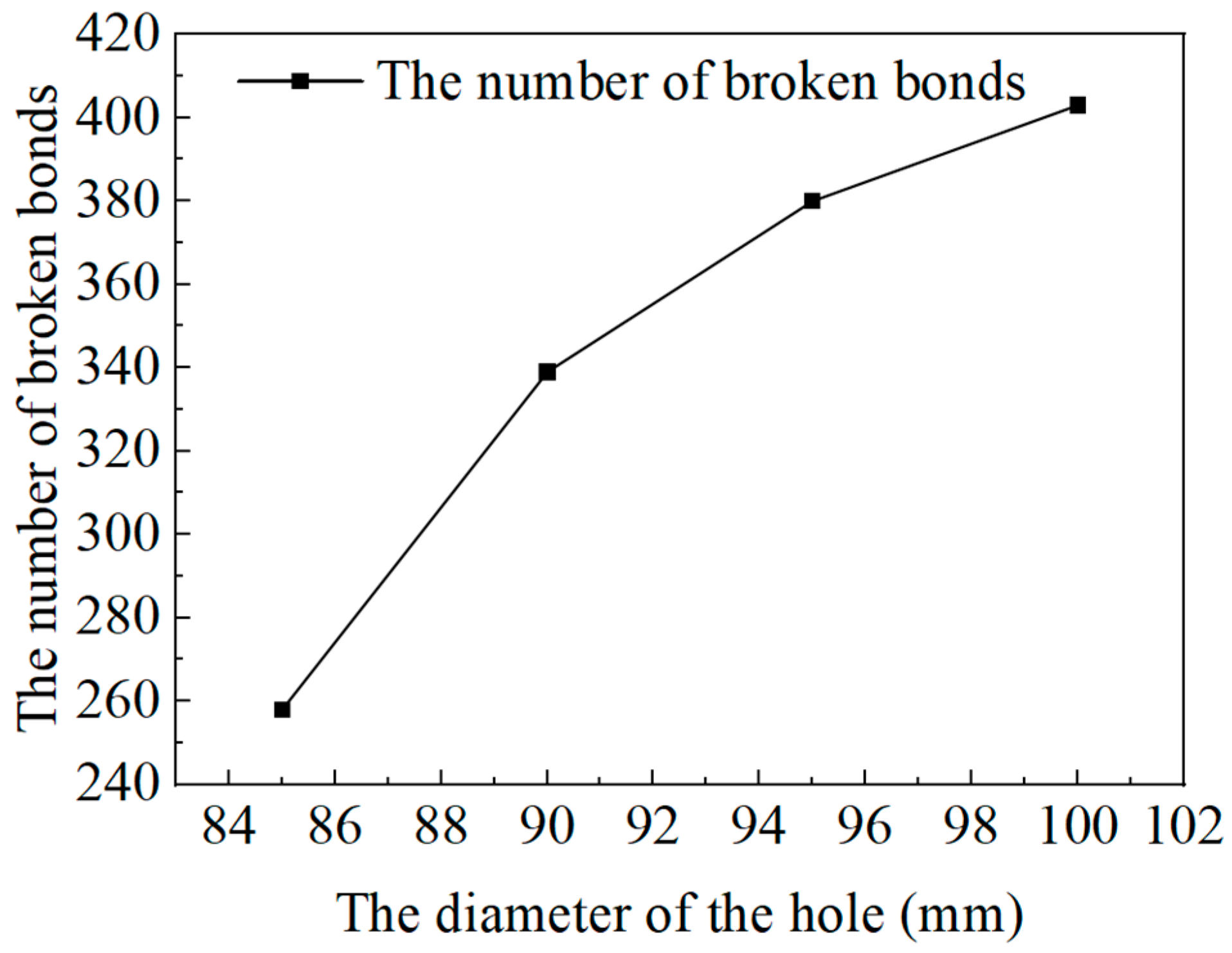
To quantitatively analyze the relationship between pre-fracturing borehole diameter and bond failures, a correlation curve depicting the bond failure count in coal-rock particles versus borehole diameter is presented in Figure 9. As shown, the number of bond failures increases in a nonlinear fashion as the hydraulic fracturing borehole diameter expands. The relationship between the number of broken bonds (N) and the aperture (d) is described by Equation (3).
N = 0.02933 × d 3 8.72 × d 2 + 868.3 × d 2.856 × 10 4
As the borehole diameter increases, the zone of damage-induced failure surrounding the borehole expands, thereby significantly enhancing the effectiveness of pre-fracturing (as illustrated in Figure 8). Consequently, the bond failure count between coal-rock particles escalates proportionally with larger borehole diameters. Specifically, when the borehole diameter increases from 85 mm to 100 mm, the bond failure count rises from 257 to 403. The simulation results further reveal that the fracture propagation radius reaches 145 mm for an 85 mm borehole diameter, expanding to 180 mm for a 100 mm borehole, representing a 24.1% increase in the hydraulic fracturing influence radius.
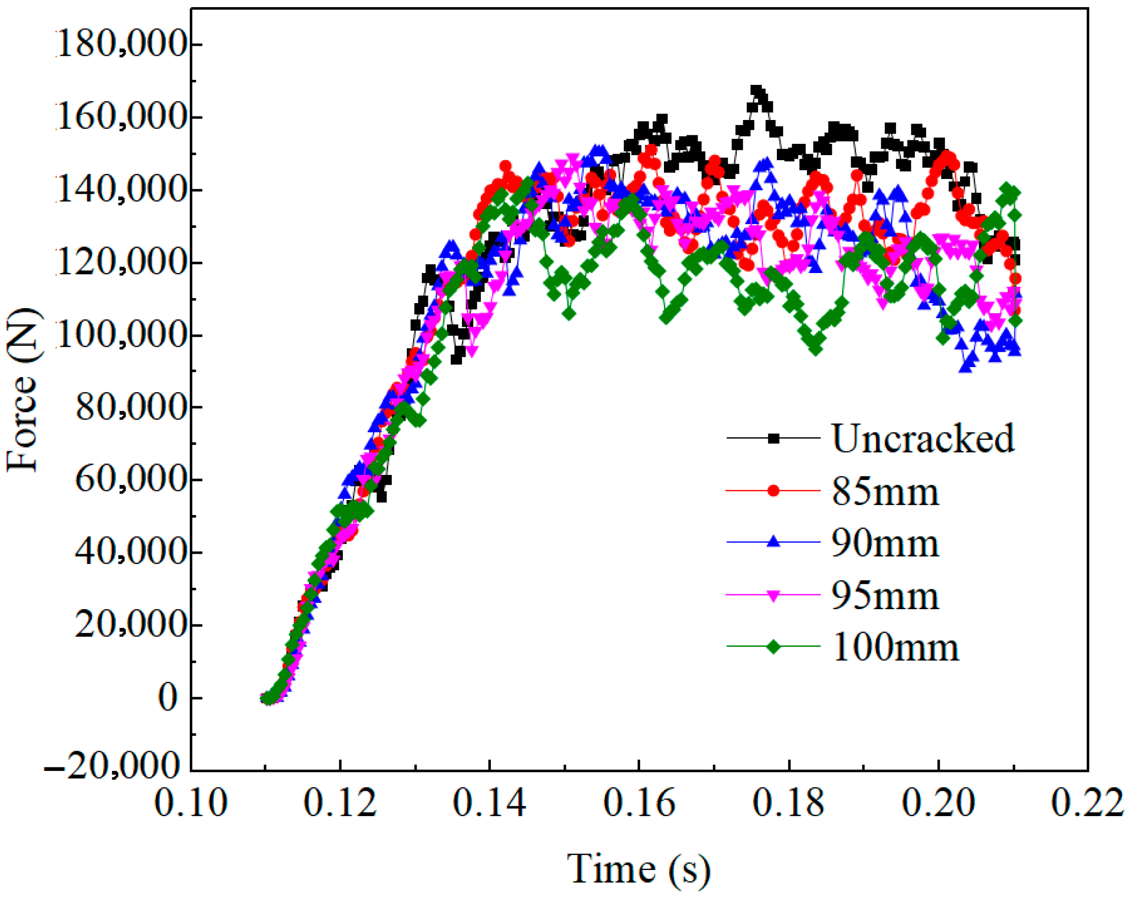
The variation curves of the resultant load on the cutter picks over time under different aperture conditions are shown in Figure 10. As depicted, when the hydraulic fracturing aperture is increased from 85 mm to 100 mm, the average force acting on the cutter picks progressively diminishes. This reduction is primarily attributed to the enhanced pre-cracking effectiveness in coal-rock masses with larger apertures, where a more extensive crack network is formed during the pre-fracturing process. The improved pre-conditioning of the coal-rock structure via hydraulic fracturing results in a reduction in the mechanical work required by cutter picks during subsequent excavation, thereby decreasing the resultant force. The measured average resultant forces at hydraulic fracturing apertures of 85 mm, 90 mm, 95 mm, and 100 mm are 115,784.3 N, 111,658.6 N, 109,025.2 N, and 104,187.4 N, respectively, each demonstrating significant reductions compared to the 120,955.2 N average resistance observed in non-preconditioned specimens. The relationship between hydraulic fracturing aperture enlargement and force reduction follows a nonlinear pattern, suggesting that optimized fracturing parameters can significantly enhance cutting efficiency by systematically reducing the forces acting on the tool. Simulation results show that the peak pick forces when cutting un-prefractured rock and pre-fractured rock with borehole diameters of 85 mm, 90 mm, 95 mm and 100 mm are 167,789.8 N, 151,259.7 N, 150,780.7 N, 1,449,127.9 N and 142,100.4 N, respectively. These results indicate a general decreasing trend of peak pick load with increasing borehole diameter. The mechanism is that larger boreholes increase the injected area and promote greater fracture density, thereby improving pre-fracturing effectiveness and reducing the maximum force experienced by the pick.

3.3. Influence of Hydraulic Fracturing Injection Pressure

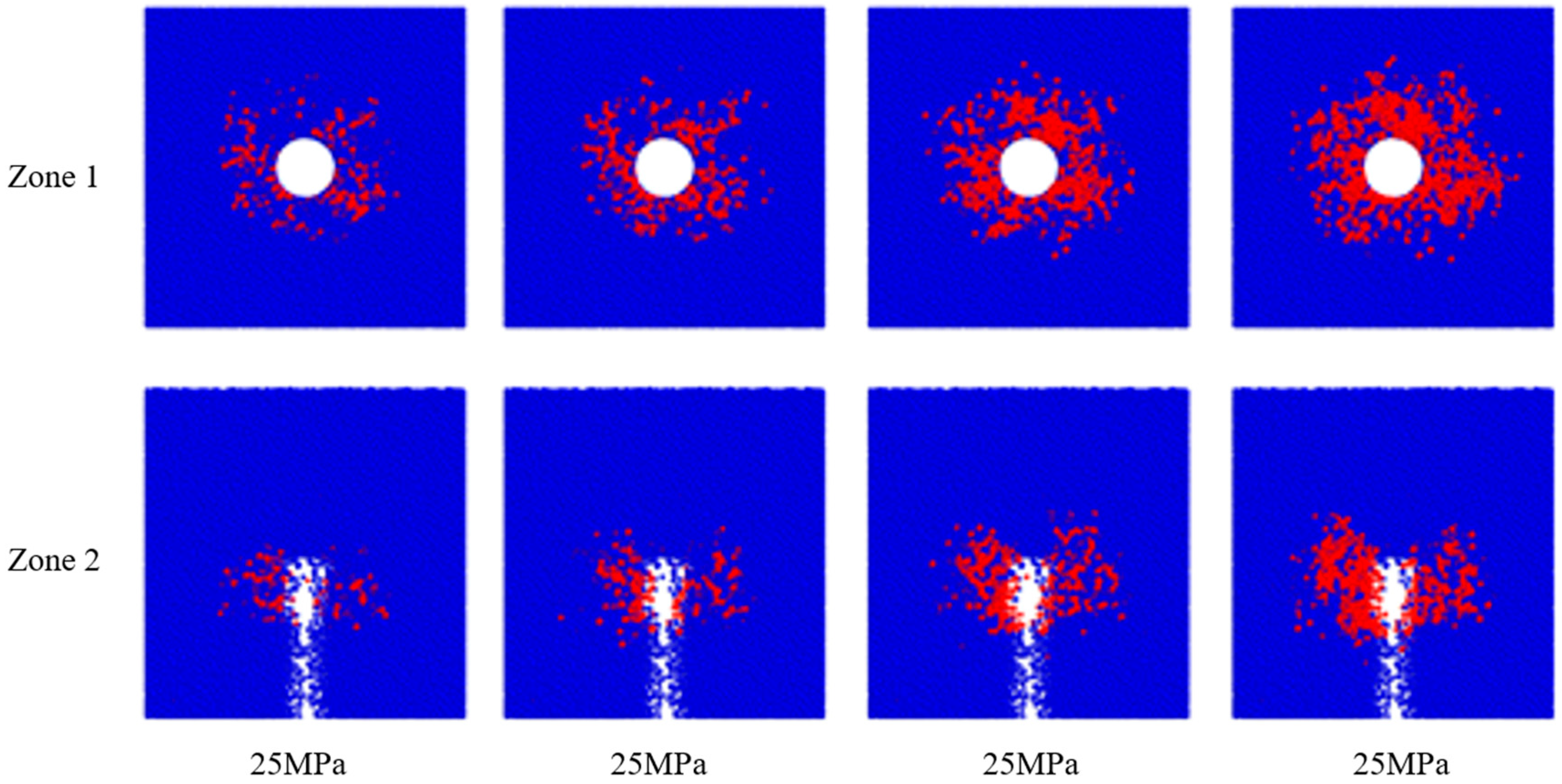
To explore the effect of injection pressure on crack propagation during pre-fracturing, simulations were conducted with a fixed borehole diameter of 90 mm and varying injection pressures of 25 MPa, 30 MPa, 35 MPa, and 40 MPa. The resulting crack patterns and bond failures under these different pressures are illustrated in Figure 11.
As shown in Figure 11, increasing the injection pressure from 25 MPa to 40 MPa leads to a progressive expansion of the hydraulic fracturing influence radius, accompanied by more extensive crack development. This enhances the overall pre-fracturing effectiveness. Specifically, higher injection pressures promote crack branching and facilitate the propagation of secondary cracks [31], as demonstrated in Figure 11.
To quantitatively examine the impact of water injection pressure on crack initiation and propagation, the number of fractured bonds in coal-rock under varying water injection pressures (25 MPa to 40 MPa) was extracted, as depicted in Figure 12. The results indicate a nonlinear increase in the number of fractured bonds as the injection pressure rises. Notably, the total crack count increases from 245 at 25 MPa to 622 at 40 MPa, illustrating that higher injection pressures substantially enhance crack propagation efficiency. The relationship between the number of fractured bonds (N) and the water injection pressure (p) is presented in Equation (4).
N = 0.01867 × p 3 1.14 × p 2 + 39.03 × p 310
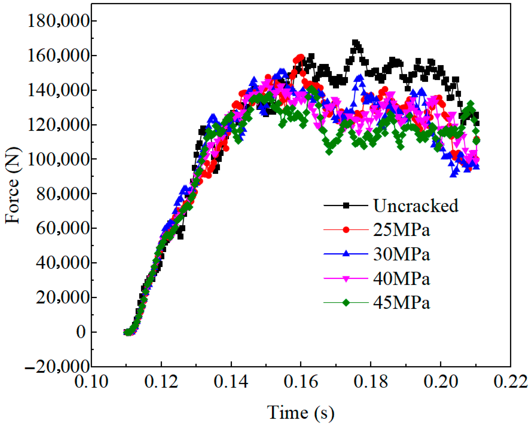
The time-dependent variation curves of the resultant load under varying water injection pressures are shown in Figure 13. Computational analysis of the resultant forces reveals that as the water injection pressure increases from 25 MPa to 40 MPa, the average forces acting on the cutter picks decrease in a monotonic fashion. The measured values of the average resultant forces at 25 MPa, 30 MPa, 35 MPa, and 40 MPa are 111,913.2 N, 111,658.6 N, 110,176.1 N, and 105,814.5 N, respectively. These values demonstrate a consistent decline, with all measurements falling significantly below the 120,955.2 N average resistance observed in non-preconditioned coal-rock. This suggests that increased injection pressure not only enhances crack propagation but also reduces the load required for excavation, further improving operational efficiency. Similarly, the simulations indicate that the peak pick forces for un-prefractured rock and rocks pre-fractured at injection pressures of 25 MPa, 30 MPa, 40 MPa and 45 MPa are 167,789.8 N, 159,362.7 N, 150,780.7 N, 145,409.5 N and 140,490.7 N, respectively. These results show that peak pick loads decrease as injection pressure increases. Higher injection pressures generate more extensive fracturing, which reduces the cutting work required and consequently lowers both the forces and their peak values.

4. Conclusions

The three-dimensional hydraulic fracturing process of rock walls was effectively simulated through CFD-DEM bidirectional coupling technology, and the interaction between tunnel boring machine (TBM) cutter heads and pre-fractured rock walls was comprehensively analyzed. The primary findings of this study are summarized as follows:
(1)
The simulation successfully captured the evolution of cracks during water-injection fracturing, progressing through four distinct phases: (i) initiation of primary cracks, (ii) growth of primary cracks with the concomitant formation of microcracks, (iii) propagation of secondary cracks in conjunction with suppressed primary crack growth, and (iv) the expansive development of secondary crack networks.
(2)
A comparative analysis revealed that the average load exerted on the cutter picks during the excavation of pre-fractured rock (111,660 N) was 9.05% lower than that encountered with intact rock (122,278.0 N). Directional decomposition of the forces demonstrated a reduction of 11.46% and 7.2% in the average loads along the Z- and Y-axes, respectively. However, this was accompanied by an increase in load fluctuations. In contrast, the X-axis exhibited a 5.49% increase in average load, coupled with a reduction in fluctuation amplitude.
(3)
Parametric investigations quantitatively assessed the influence of hydraulic aperture (ranging from 85–100 mm) and injection pressure (ranging from 25–40 MPa) on the formation of fracture networks and cutting mechanics. The number of fractured bonds exhibited nonlinear growth with both parameters: increasing from 257 to 403 with aperture enlargement and from 245 to 622 with an increase in injection pressure. Correspondingly, the average resultant forces on the cutter picks exhibited a systematic decrease, from 115,784.3 N to 104,187.4 N with aperture variation, and from 111,913.2 N to 105,814.5 N with pressure variation. These forces were consistently 12–15% lower than the baseline resistance of 120,955.2 N observed in non-preconditioned rock. These findings substantiate that the optimization of hydraulic preconditioning parameters can substantially enhance excavation efficiency by fostering the development of controlled fracture networks and reducing the dissipation of mechanical energy.

Author Contributions

Q.D.: Project administration, Investigation, Methodology, Resources, Writing—original draft, Writing—review and editing. C.L.: Data curation, Methodology, Software, Visualization, Writing—review and editing. H.L.: Investigation, Methodology, Supervision, Writing—review and editing. Q.L.: Investigation, Software, Validation, Writing—review and editing. Y.X.: Investigation, Supervision, Writing—review and editing. All authors have read and agreed to the published version of the manuscript.

Funding

This work was supported by the Liaoning Provincial Department of Education Project (JYTMS20230805).

Data Availability Statement

Data is contained within the article.

Acknowledgments

We gratefully appreciate the financial support from the Liaoning Provincial Department of Education Project (JYTMS20230805).

Conflicts of Interest

Author Qingwei Liu was employed by the company Fujinson (Nantong) Technology Co., Ltd. The remaining authors declare that the research was conducted in the absence of any commercial or financial relationships that could be construed as a potential conflict of interest.

References

  1. Liu, S.; Li, H.; Jiang, H.; Zhang, Q.; Cui, Y.; Liu, X. Research progress of coal-rock breaking methods in mines. J. China Coal Soc. 2023, 48, 1047–1069. [Google Scholar] [CrossRef]
  2. Huang, B.X. Research on theory and application of hydraulic fracture weakening for coal-rock mass. J. China Coal Soc. 2010, 35, 1765–1766. [Google Scholar] [CrossRef]
  3. Sun, S.; Zhang, S.; Mang, X.; Zou, Y. Study on fractures propagation mechanism in coal hydraulic fracturing based on high-energy CT scanning technique. J. Henan Polytech. Univ. (Nat. Sci.) 2020, 39, 18–25. [Google Scholar] [CrossRef]
  4. Lu, S.; Wang, S.; Liu, H.; Li, R.; Dong, Q.; Xiao, Y.; Shen, P. Analysis of the influence of natural fracture system on hydraulic fracture propagation morphology in coal reservoir. J. China Coal Soc. 2020, 45, 2590–2601. [Google Scholar] [CrossRef]
  5. Heider, Y. A review on phase-field modeling of hydraulic fracturing. Eng. Fract. Mech. 2021, 253, 107881. [Google Scholar] [CrossRef]
  6. Zhang, Y.; Shao, J.; Liu, Z.; Shi, C. An improved hydromechanical model for particle flow simulation of fractures in fluid-saturated rocks. Int. J. Rock Mech. Min. Sci. 2021, 147, 104870. [Google Scholar] [CrossRef]
  7. Chong, Z.; Yao, Q.; Li, X.; Liu, J. Investigations of seismicity induced by hydraulic fracturing in naturally fractured reservoirs based on moment tensors. J. Nat. Gas Sci. Eng. 2020, 81, 103448. [Google Scholar] [CrossRef]
  8. Chong, Z.; Yao, Q.; Li, X.; Zhu, L.; Tang, C. Effect of rock brittleness on propagation of hydraulic fractures in shale reservoirs with bedding-planes. Energy Sci. Eng. 2020, 8, 2352–2370. [Google Scholar] [CrossRef]
  9. Kang, H.; Feng, Y.; Zhang, Z.; Zhao, K.; Wang, P. Hydraulic fracturing technology with directional boreholes for strata control in underground coal mines and its application. Coal Sci. Technol. 2023, 51, 31–44. [Google Scholar] [CrossRef]
  10. Zhao, K.K.; Zhang, Z.; Li, W.Z.; Wang, X.H.; Yin, K.; Sun, Z.Y. Three-dimensional simulation of hydraulic fracture from a borehole using XSite. Chin. J. Geotech. Eng. 2021, 43, 1483–1491. [Google Scholar] [CrossRef]
  11. Zhao, K.K. Three-Dimensional Propagation of Hydraulic Fracture from Regional Fracturing in Hard Roof. Ph.D. Thesis, China Coal Research Institute, Beijing, China, 2021. [Google Scholar] [CrossRef]
  12. Sun, Q.; Song, W. Optimization simulation analysis of hydraulic fracturing parameters of rock roadway machine excavation face. Energy Technol. Manag. 2024, 49, 14–17. [Google Scholar] [CrossRef]
  13. Liu, J. Research on Breaking Characteristics of Hard Coal with High-Pressure Water Presplitting and Cutting Picks. Ph.D. Thesis, Liaoning Technical University, Fuxin, China, 2022. [Google Scholar] [CrossRef]
  14. Cundall, P.A.; Strack, O.D.L. A discrete numerical model for granular assembles. Geotechnique 1978, 29, 47–65. [Google Scholar] [CrossRef]
  15. Liu, Z.; Zhang, Q. PFC numerical analysis on crack initiation mechanism of fracture grouting in top of Ordovician limestone. Coal Geol. Explor. 2023, 51, 72–85. [Google Scholar] [CrossRef]
  16. Wu, L.; Yu, C.; Liang, Z.; Duan, W.; Cheng, M. Study on Formation Process of Underwater Bench Blasting Pile based on Fluid-structure Coupling Algorithm of Fluent-EDEM. Blasting 2023, 40, 37–43+123. [Google Scholar] [CrossRef]
  17. Chen, S.; Niu, Y.; Lu, X.; Yang, J.; Dong, Z.; Feng, B. Simulation and experiment of linear wibrating screen for sallop meat and shell eparation based n discreeelement method. J. Chin. Agric. Mech. 2023, 44, 107–114. [Google Scholar] [CrossRef]
  18. Ji, C.; Guan, Y.; Zheng, H.; Zhang, M. Effect of Particle Size on Performance of Slurry Pump in Deep Sea Mining. Min. Metall. Eng. 2021, 41, 1–6. [Google Scholar] [CrossRef]
  19. Zhang, W.; Bu, T. Mesoscopic Simulation of Failure and Crack Development of Coal-rock Combination Under Different Confining Pressure. Saf. Coal Mines 2017, 48, 45–48+52. [Google Scholar] [CrossRef]
  20. Zhang, L.; Liu, Y. Analysis of Coal-rock Damage Evolution and Acoustic Emission Characteristics Based on Particle Discrete Element Model. Saf. Coal Mines 2017, 48, 213–216. [Google Scholar] [CrossRef]
  21. Zhou, T.; Yang, X.; Han, X. Numerical inversion simulation of coal rock under uniaxial compression failure in, P.F.C.2.D. J. Min. Sci. Technol. 2017, 2, 260–266. [Google Scholar] [CrossRef]
  22. Cheng, J.; Cao, Y.; Dou, Y.; Li, Z. Erosion of water-based fracturing fluid containing particles in a sudden contraction of horizontal pipe. J. Phys. Conf. Ser. 2017, 916, 12–27. [Google Scholar] [CrossRef]
  23. Li, X.; Niu, Z.; Yao, Q.; Wang, W.; Yu, L. Particle flow analysis of crack propagation characteristics of hole-type trident cracks sandstone. J. China Coal Soc. 2020, 45, 3735–3747. [Google Scholar] [CrossRef]
  24. Zhang, Q. Experimental and Numerical Research on Rock Cutting by Roadheader Picks. Ph.D. Thesis, Taiyuan University of Technology, Taiyuan, China, 2016. Available online: https://kns.cnki.net/kcms2/article/abstract?v=F0lYaGTXfx_a0xVNQNuEBX74REvOXS23qJzS4fQlOZLGuhNZM3__by4RCJCmQQ23QFyfpIqDm6OsN8V7gjLSDuJl-3uSYM_rExJ8-b4jl8Q4TMsQGK_5bzMv-34o2ktX7mPnI4tHDHLlNuFLFXB7x49xS6wFvGKyTKbP5JoUpy_4bb1hbrE8zQ==&uniplatform=NZKPT (accessed on 1 January 2025).
  25. Wang, Y. Study on Self-Adaptive Cutting Control of Shearer Based on CPS. Ph.D. Thesis, Liaoning Technical University, Fuxin, China, 2022. [Google Scholar] [CrossRef]
  26. Sun, S.; Li, W.; Zhang, J.; Chen, D.; Zhao, J.; Zheng, K.; Long, W.; Wang, C.; Jia, B.; Du, T.; et al. Research progress and development trend of staged hydraulic fracturing technology in long-borehole underground coal mine. Coal Geol. Explor. 2022, 50, 1–15. [Google Scholar] [CrossRef]
  27. Xu, D. Separation Mechanism and Application of Microchannels in Particle Beds Based on CFD-DEM. Master’s Thesis, Chongqing University of Technology, Chongqing, China, 2025. [Google Scholar] [CrossRef]
  28. Zhang, Y. Research on Technology and Craft of Hard Rock Roadway Fast Excavation Based on Breaking Rock Assisted by Hydraulic Fracturing. Master’s Thesis, China University of Mining and Technology, Xuzhou, China, 2022. [Google Scholar] [CrossRef]
  29. Li, Q.; Deng, Y.; Hu, Q.; Zhang, Y.; Song, M.; Liu, J.; Shi, J. Mesoscopic law of stress and fracture evolution of coal seams hydraulic fracturing. Coal Geol. Explor. 2022, 50, 32–40. [Google Scholar] [CrossRef]
  30. Zhao, L.; Yang, S.; Zhang, H.; Han, L. Fatigue life prediction of shearer rocker shell based on DEM-MFBD bidirectional coupling technology. Coal Sci. Technol. 2023, 51, 252–258. [Google Scholar] [CrossRef]
  31. Liu, Z. Study on Hard Rock Hydraulic Fracturing Pretreatment Technology in 51207 Head of Chamber Guojiawan Coal Mine. Master’s Thesis, China University of Mining and Technology, Xuzhou, China, 2022. [Google Scholar] [CrossRef]
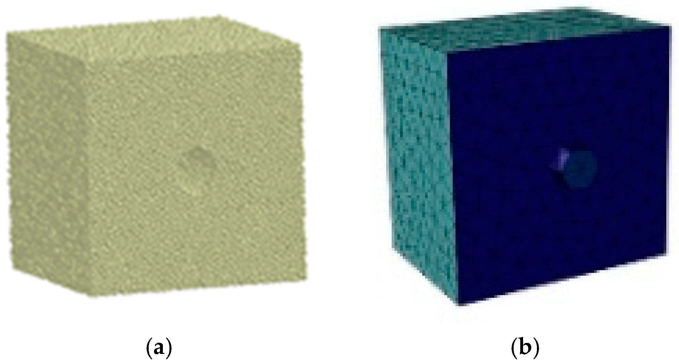
Figure 1. Model Diagram. (a) Parallel Bond Model (b) Hertz-Mindlin Particle Contact Model.
Applsci 15 11696 g001
Figure 2. Model Diagram. (a) Discrete Element Rock Wall Model (b) Fluid Domain Rock Wall Model.
Applsci 15 11696 g002
Figure 3. Location of the regions.
Applsci 15 11696 g003
Figure 4. Evolution law of rock wall pre-cracking.
Applsci 15 11696 g004
Figure 5. Fracture propagation pattern induced by hydraulic fracturing. (a) The results from this study. (b) The results from this study. (c) Zhang Y’s simulation results. (d) Zhao KK’s experimental results.
Applsci 15 11696 g005
Figure 6. Resultant load curve.
Applsci 15 11696 g006
Figure 7. Triaxial force load curve.
Applsci 15 11696 g007
Figure 8. Diagram of Crack and Fracture Bond under Different Aperture Sizes.
Applsci 15 11696 g008
Figure 9. Number of Broken Bonds at Different Borehole Diameters.
Applsci 15 11696 g009
Figure 10. Resultant Load Curve at Different Borehole Diameters.
Applsci 15 11696 g010
Figure 11. Diagram of Crack and Fracture Bond under Varying Injection Pressures.
Applsci 15 11696 g011
Figure 12. Number of Broken Bonds under Different Injection Pressures.
Applsci 15 11696 g012
Figure 13. Resultant Load Curve under Different Injection Pressures.
Applsci 15 11696 g013
Table 1. Physical and Mechanical Parameters of Coal and Rock.
ParametersValues
Density (kg/m3)2600
Compressive Strength (MPa)71
Elastic Modulus (MPa)21,500
Poisson’s Ratio0.19
Protodyakonov Strength Coefficient (f-value)8.4
Coefficient of Restitution0.45
Static Friction Coefficient0.48
Kinetic Friction Coefficient0.109
Parallel Bond Normal Stiffness (N/m3)2.2017 × 109
Parallel Bond Tangential Stiffness (N/m3)1.8775 × 109
Parallel Bond Normal Maximum Stress (MPa)28.936
Parallel Bond Tangential Maximum Stress (MPa)12.174
Table 2. Parameters.
Contact Parameters Between Cutting Teeth and Rock WallsCutting Head Cutting Tooth Motion ParametersCutting Material Parameters
Coefficient of RestitutionStatic Friction CoefficientVibrational Friction CoefficientRotational Speed (r·min−1)Traverse Speed (m·min−1)Density (kg·m−3)Shear Modulus (GPa)Poisson’s Ratio
Value0.20.70.1451.47800700.3
Disclaimer/Publisher’s Note: The statements, opinions and data contained in all publications are solely those of the individual author(s) and contributor(s) and not of MDPI and/or the editor(s). MDPI and/or the editor(s) disclaim responsibility for any injury to people or property resulting from any ideas, methods, instructions or products referred to in the content.