Review

Electroconductive Thermosensitive Shape Memory Polymers Manufactured by Fused Filament Fabrication: A Critical Review

by
Laurane Roumy
1,2,3,
Fabienne Touchard
1,
Thuy-Quynh Truong-Hoang
2 and
Francisca Martinez-Hergueta
3,*
1
Département Physique et Mécanique des Matériaux, Institut PPRIME, CNRS-ENSMA-Université de Poitiers, ENSMA, 1 Av. C. Ader, B.P. 40109, 86961 Futuroscope Cedex, France
2
ESTACA’Lab-Laval, ESTACA, 53000 Laval, France
3
Institute for Infrastructure and Environment, School of Engineering, University of Edinburgh, Edinburgh EH9 3FG, UK
*
Author to whom correspondence should be addressed.
Appl. Sci. 2025, 15(21), 11641; https://doi.org/10.3390/app152111641 (registering DOI)
Submission received: 15 September 2025 / Revised: 20 October 2025 / Accepted: 29 October 2025 / Published: 31 October 2025
(This article belongs to the Special Issue State of the Art in Smart Materials and Flexible Sensors)

Abstract

The field of 4D printing has seen rapid advancement in recent years, making it a highly dynamic research domain. This new technology is promising for the development of brand-new lightweight, smart and reliable devices. This article is a literature review of the latest research in 4D printing, focusing on electroconductive thermosensitive Shape Memory Polymers. They are promising thanks to their high strength-to-weight ratio and their large deformability. However, devices made of such materials are difficult to embed into larger systems because of the triggering mechanism needed to actuate them. Electroconductive Shape Memory Polymers can be stimulated by the Joule effect, but the intricacies and interdependence of their properties make them a great scientific challenge. The first part of this article provides a clear explanation of the main concepts of 4D printing. Afterwards, it focuses on Fused Filament Fabrication due to its high customisability and ease of use. A description of the properties of thermosensitive 4D printed specimens is provided in the third part. Finally, their main challenges and intricacies are discussed.

1. Introduction

Four-dimensional (4D) printing is a state-of-the-art technology that combines the easy manufacturing, customisation of complex structures and minimum waste production, with smart materials that integrate functionalisation thanks to an external stimuli without needing human intervention nor motors [1]. This new technology is very promising for the development of intelligent, lightweight and reliable systems, for example, in the space industry, where the development of new structures, devices and space mechanisms focuses on minimising both the cost and weight of the components while enhancing their performances. In environments where human intervention is nearly impossible such as space or medicine for instance, it is even more necessary to design reliable devices with as little default sources as possible and almost no maintenance needed. In particular, actuators that convert electrical, hydraulic, thermal or pneumatic energy into a mechanical motion are at the centre of attention.
Shape Memory Alloys are already used for this kind of application, but Shape Memory Polymers (SMPs) are increasingly being considered due to their high strength-to-weight ratio and large deformability [2]. Thermosensitive SMPs have been widely studied in 4D printing, but electrically conductive SMPs that offer the advantages of remote and internal heating by the Joule effect, removing the need for an external heat source, are very promising. Actuators made with such materials can be easily embedded in larger structures [3,4].
To comprehend the emerging field of 4D printing, it is yet necessary to clarify some of the many concepts that are brought together under this name. This article provides a state-of-the-art literature review of 4D printing research focusing on electroconductive thermosensitive Shape Memory Polymers. The first part aims to give a clear explanation of the main concepts of 4D printing. Many types of additive manufacturing are available on the market, but printing by Fused Filament Fabrication (FFF) is discussed in the second part due to its versatility, customisation possibilities and ease of use. The materials used can be combined for their specific properties, such as the bilayer effect, or for their shape memory properties. The latter can be polymers, metal alloys or ceramics. In particular, thermosensitive Shape Memory Polymers are widely studied, but they are mainly heated by an external source by immersing the prototype in a hot water bath or placing it in an oven. Hence, there is interest in studying polymers reinforced with conductive particles to improve mechanical performance and achieve internal heating through the Joule effect, thereby opening the way to embedding the device in a larger structure. The properties of such materials are discussed in the third part. Finally, the main challenges and obstacles are highlighted.

2. Four-Dimensional Printing

Four-dimensional (4D) printing has emerged from the observation of the natural environment: sunflowers following the sun, pinecones’ scales opening in a dry atmosphere or flytrap plants closing when they sense food represent relevant bioinspired engineering examples (Figure 1).
To recreate these phenomena, 4D printing combines additive manufacturing with smart materials reacting to an external stimulus, the fourth dimension being time [1]. Therefore, this technique keeps the advantages of three-dimensional (3D) printing such as less waste production and the ease to create complex structures, as well as taking advantage of the intelligence-triggered behaviour of smart materials that can be sensitive to heat [7], light [8], magnetic field [9], humidity [10] or electricity [11], for instance.

2.1. Concept

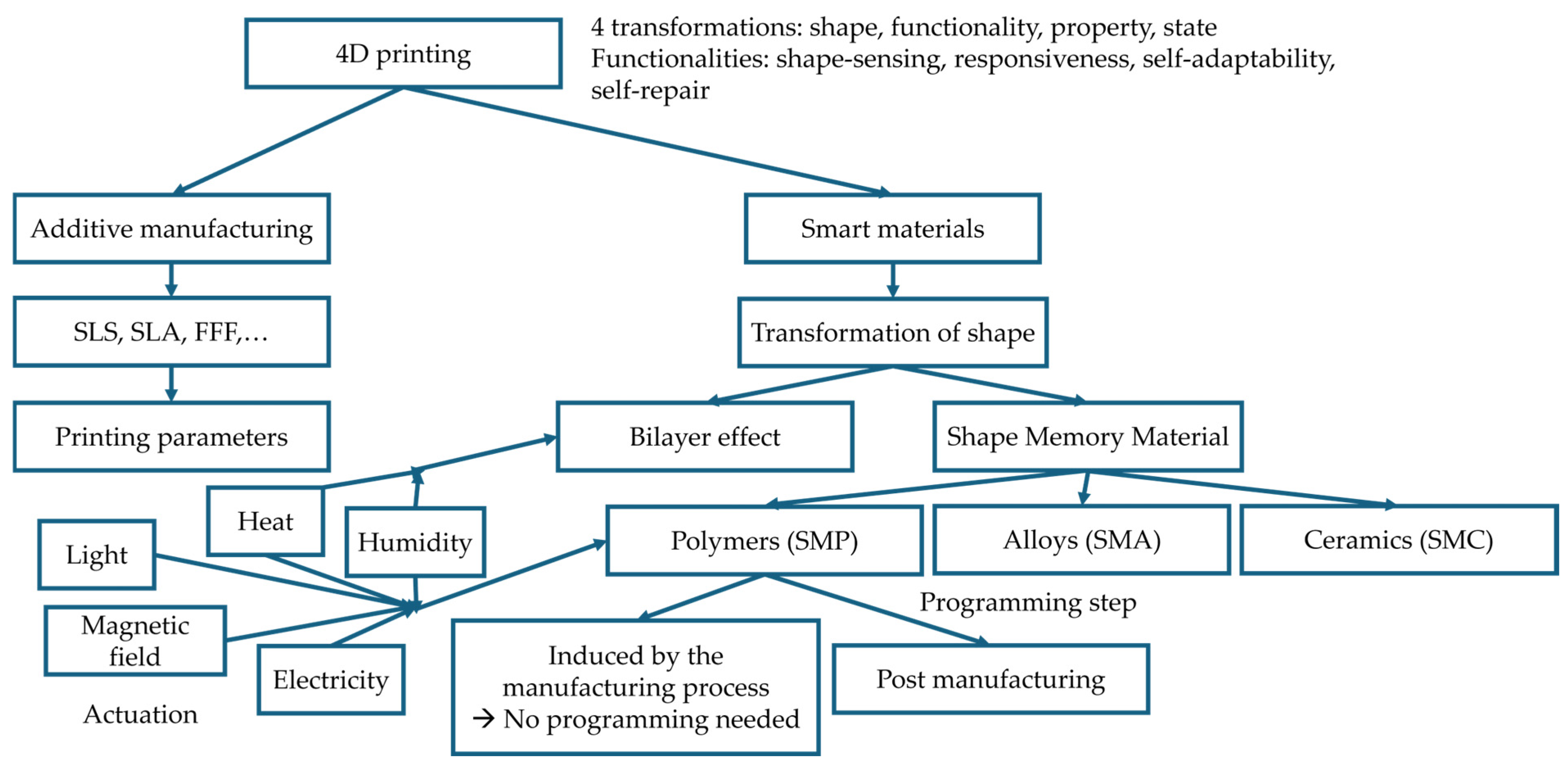
The overall concept of 4D printing is explained in Figure 2. Four-dimensional printing enables four types of transformation: property, state, functionality and shape [12]. For instance, a change in property involves the polymerisation of a material under heating, allowing self-healing structures [13], or a change in colour with thermosensitive pigments [14]. A change in state may stand for a semi-crystalline thermoplastic polymer going from its rubbery state to its melted state above its melting point [15]. The change in functionality includes self-repair, shape-sensing, responsiveness or self-adaptability. They can be found one at a time in a device, but 4D printing also enables the creation of multifunctional structures such as drug carriers [16].
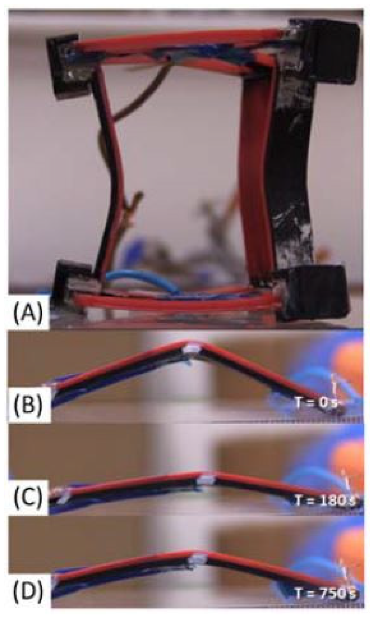
On the other hand, shape transformation can be achieved by two means: the bilayer effect or the use of Shape Memory Materials. The bilayer effect consists of the use of two materials with distinct physical properties that respond differently to a stimulus, thus inducing shapeshifting. The most common example is the bilayer with different thermal expansion coefficients: the material with the largest thermal expansion coefficient forces a bending motion on the other material [17] (Figure 3). This category also includes hydromorphic materials such as 4D-printed continuous flax fibres reinforced composites [18] or humidity-sensitive polymers that react to the moisture content of the environment [19,20].
Shape Memory Materials can also be used individually for 4D printing. This includes Shape Memory Polymers (SMPs), Shape Memory Ceramics (SMCs) [22], or Shape Memory Alloys (SMAs). The latter are far more expensive to use than SMPs as the additive manufacturing processes available for alloys consist of sophisticated equipment such as laser powder bed fusion [23]. The shape memory behaviour of SMA is also more complex and allows only small deformations but enable reversible actuation [24].

2.2. Applications

Four-dimensional printing has various potential applications. The versatility of stimuli-sensitive SMPs enables the creation of structures that are actuated by simply being in the environment. For example, meteosensitive bilayer structures can track the sun by utilising the air’s relative humidity throughout the day [10]. A pill made of a thermosensitive shape memory polymer can sense a modification in its environment and react to it when its temperature changes, releasing its load in the body by opening itself before being biodegraded [16].
Four-dimensional printing also enables the manufacturing of electrodes in electrochemistry. Abdalla et al. [25] worked with 3D-printed PLA reinforced with carbon black particles (CB/PLA) and Junpha et al. [26] used CNT/PLA, CNT/copper and CNT/zinc oxide 3D-printed by FFF to study the stability of the composites under corrosive cyclic voltametric conditions.
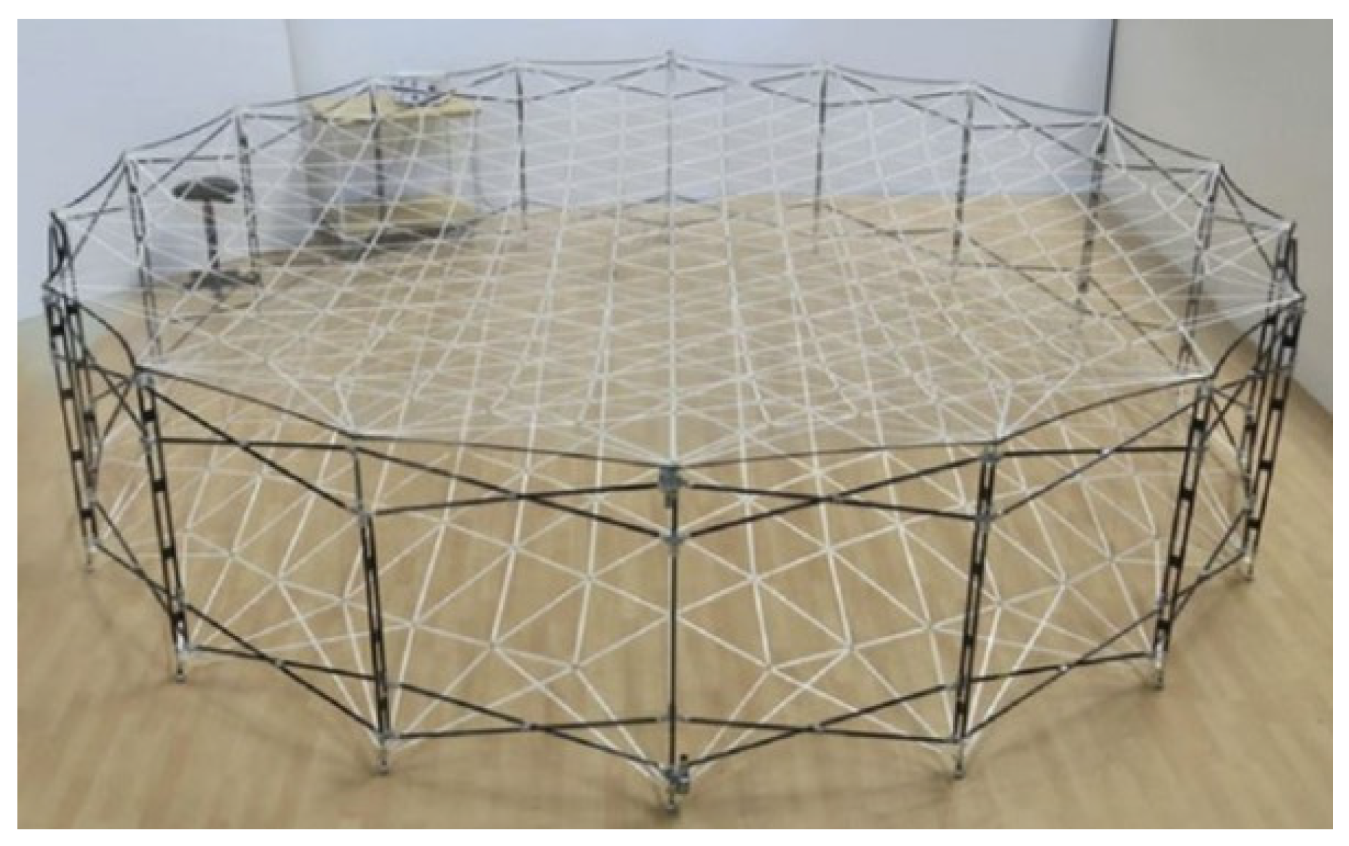
In aerospace, morphing structures have been conceived, like, for example, self-deployed antennas (Figure 4) [27]. Four-dimensional printing enables the conception of embedded, customised and stimuli-sensitive structures for environments where human action is often limited; a failure of a motor would be critical, and in some cases, conventional manufacturing might not be possible.
In healthcare, even though the environment is different, the same constraints apply. On-demand tailored manufacturing is essential for devices that need to be fit to the patient’s body, regarding stents or splits (Figure 5a,b), for example.
Another field gathering a lot of effort around 4D printing is soft robotics [28,29]. Actuators such as grippers [30] and hinges (Figure 5c), rehabilitation devices [31] or joints to mimic the movement of a hand [32] are many examples of soft structures that can be conceived.
Figure 5. (a) Example of a thermosensitive stent [7] (source: Creative Commons Attribution 4.0 international licence) and (b) surgically implanted splints [33] (source: Creative Commons Attribution licence). (c) Hybrid hinge structure that can also be used as a gripper (source: reproduced with permission from Elsevier [34]).
Applsci 15 11641 g005
However, most of the time, the devices are shown to perform independently without being integrated into a larger mechanism, which is crucial to explore for practical applications. Depending on the application, the load needed to deform the sample, or the load deployed during the actuation step needs to be evaluated. Barletta et al. [35] conceived an auxetic structure for energy-absorbing barriers, and measured the compression load needed to programme the sample, which corresponds to the maximum load that could be seen by this structure if subjected to an impact, measured equal to 0.45 kN. The aim of this is for the energy-absorbing barrier to be able to be reused, so the recovery aims to give it its initial shape back, after compression. On the other hand, the force deployed during the actuation step, which can also be called recovery force, has been studied by some authors. Akbari et al. [36] studied a morphing wing flap and a deployable structure 3D-printed by ink jetting. The SMP used is heated by the Joule effect thanks to embedded wires, and the recovery force is measured using weights hung to the samples. Lalegani Dezaki et al. [30] used the same measurement means with a gripper made of SMA, epoxy composite and fibre-reinforced composite able to lift up to 300 g. Liu et al. [37] considered a beam made of silicone elastomer filled with CNT and measured its recovery force thanks to a three-point bending setup by Dynamic Mechanical Analysis (DMA) heated in an oven from 25 °C to 90 °C. The force deployed reached a maximum of 0.22 N. Wang et al. [38] studied a polyester paper bilayer gripper 3D-printed by FFF. A custom-made setup was developed to measure the force of the sample triggered in an oven and was able to deploy up to 8.1 N.

3. Fused Filament Fabrication

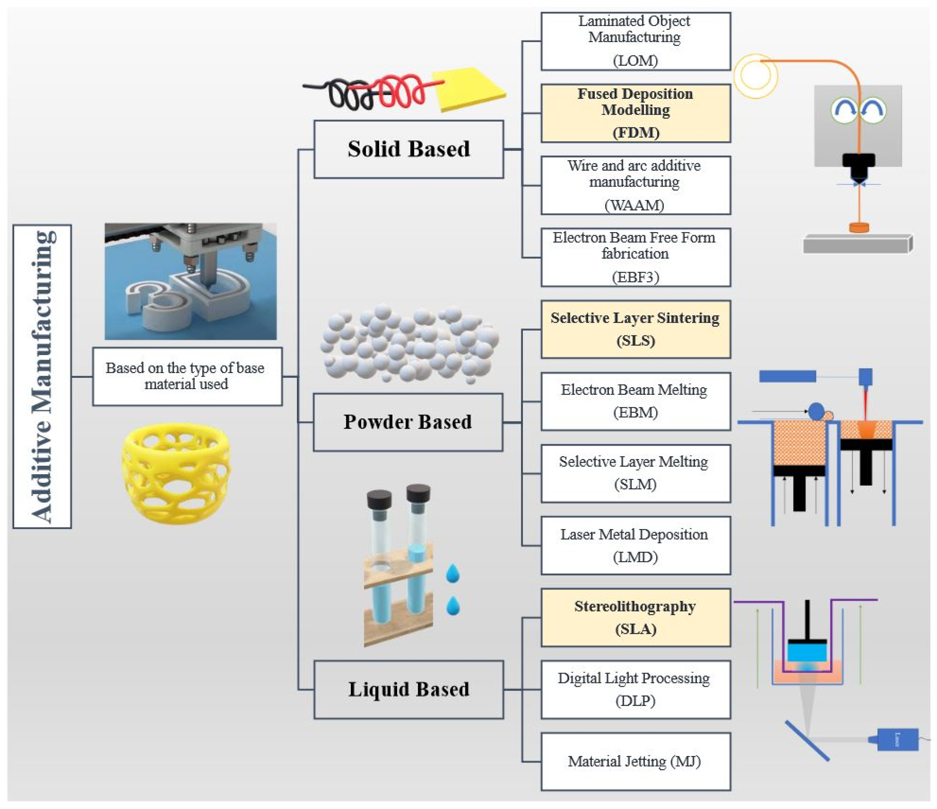
Additive manufacturing is based on three types of materials: solid, powder or liquid. Various 3D printing methods exist, described in Figure 6. But additive manufacturing of polymers is receiving growing attention [21]. Among them, Fused Filament Fabrication (FFF), also called Fused Deposition Modelling (FDM), is advantageous due to its affordability, ease of use, fast manufacturing capabilities and versatility [39]. The raw material usually consists of a spool of continuous polymer filament fed to a heated nozzle through an extruder. The melted material is then deposited as filaments onto a heated bed, creating a 3D structure following a set path layer by layer [40].

3.1. Processing Parameters

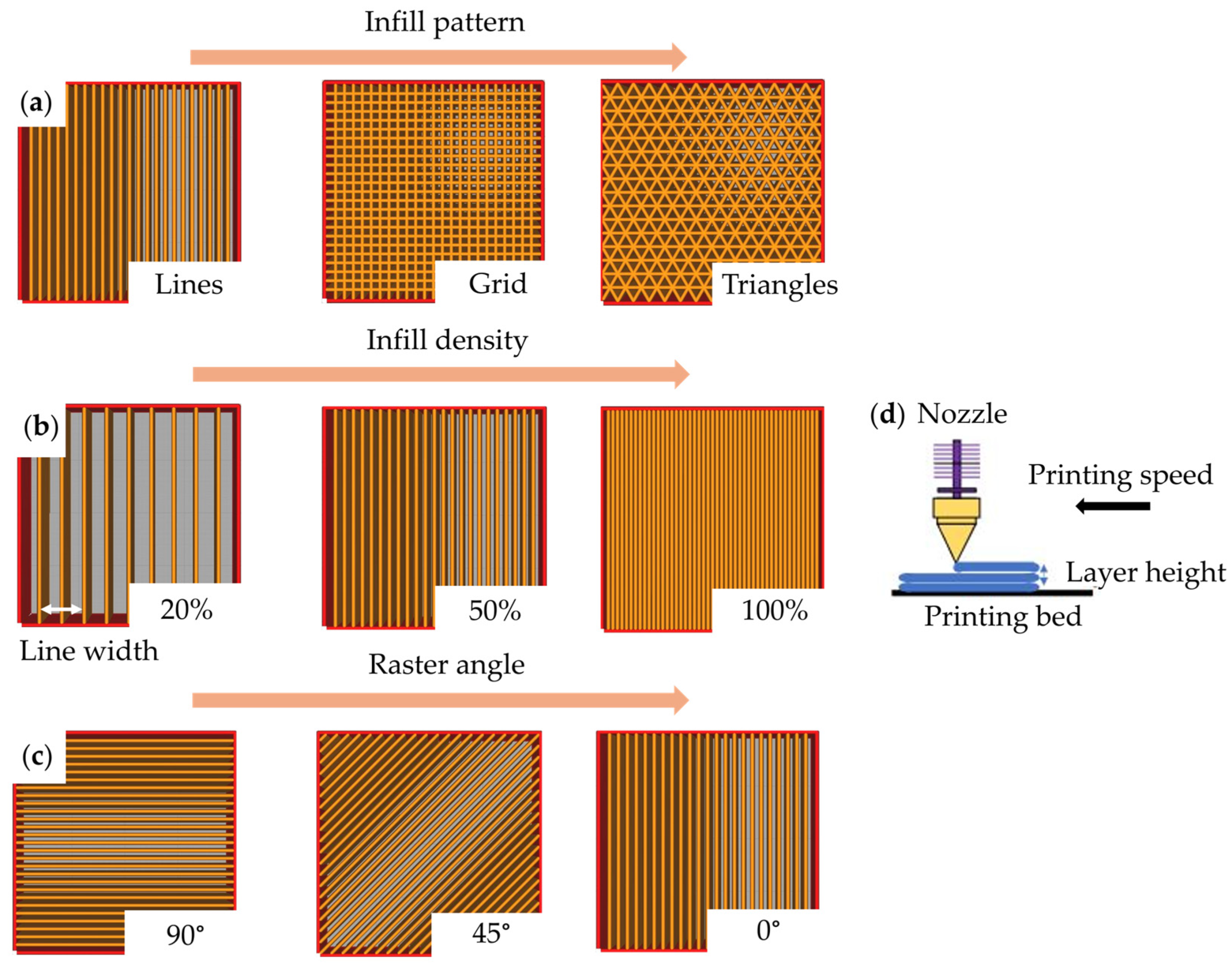
A lot of printing parameters can be taken into account in the design of a 3D-printed structure by FFF. The most common ones are described in Figure 7. The infill pattern defines the main path the nozzle is going to take to fill in the geometry of the structure (Figure 7a). The infill density represents the amount of material that is used to fill the printed part (Figure 7b). The line width is the distance between two consecutive printed lines. It is expressed for every kind of infill patterns and is directly impacted by the infill density. The raster angle gives the angle at which a pattern of lines is going to be printed compared to the x axis of the printer (Figure 7c). The layer height is the distance between two consecutive layers. The printing speed is the speed at which the nozzle is following its path to deposit the filaments of material (Figure 7d). Many more parameters can be changed to achieve the desired geometry, which is also one of the advantages of FFF printing. Slicing software, made to calculate the best path depending on the 3D structure wanted, such as Ultimaker Cura 5.0.0, usually give default values of parameters based on the material and the nozzle diameter used.

3.2. Four-Dimensional-Printed Thermosensitive Shape Memory Polymers

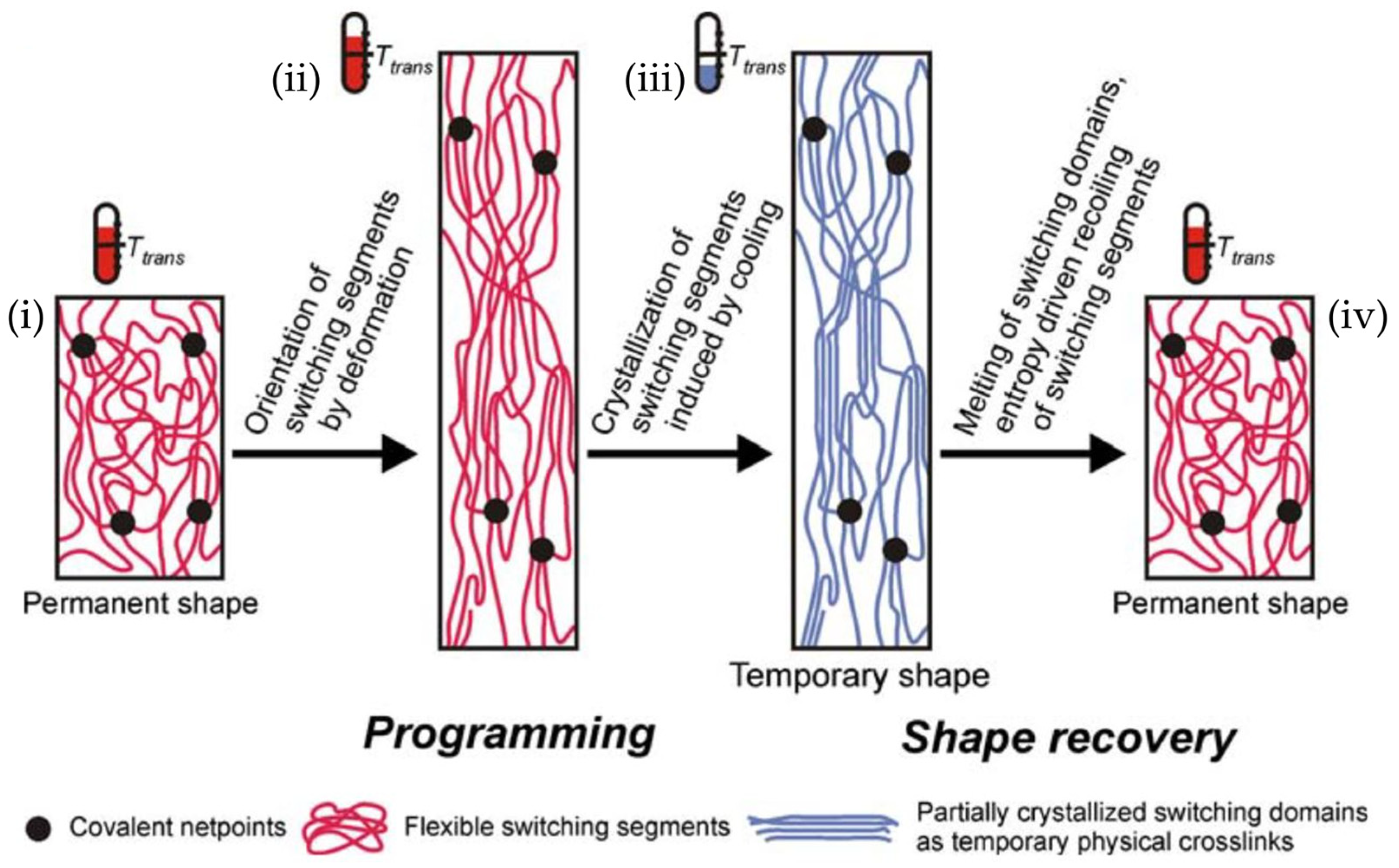
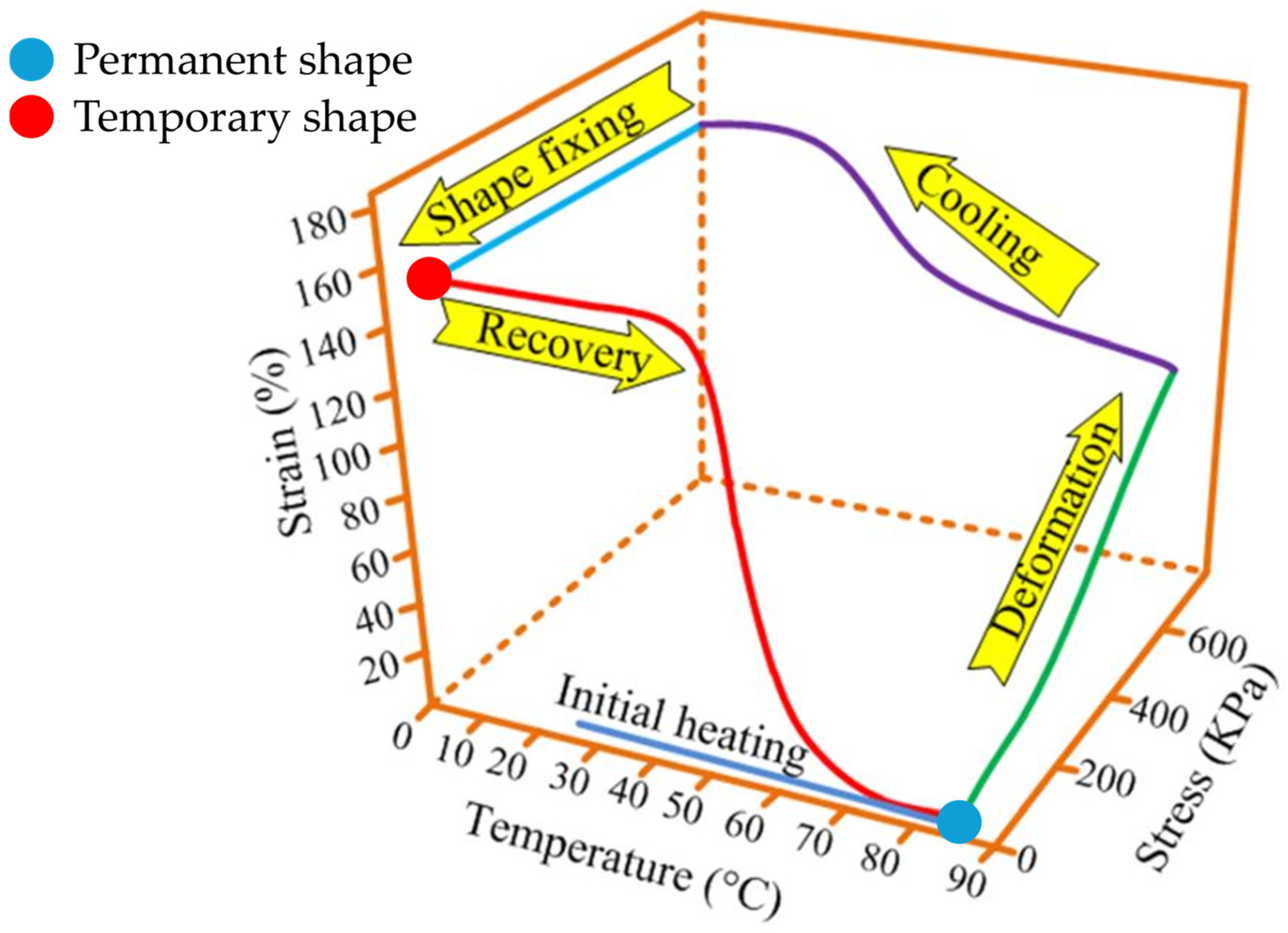
The primary material used in FFF printing is polymers, including thermosensitive Shape Memory Polymers (SMPs). The physics behind their shapeshifting ability resides in the different physical states they can go through when heated. The melted extruded polymer is consolidated as a sample in its permanent shape (Figure 8). Then, the sample is (i) heated above its glass transition temperature T g , (ii) deformed to its temporary shape and (iii) fixed by cooling down the structure. Consequently, the shape memory effect takes place when (iv) the sample is heated again above its T g [43]. This is due to the fact that the polymer chains seek to reach thermodynamic equilibrium, i.e., minimise the difference between their internal energy and entropy. One way to achieve this is by allowing the polymer chains to move. This is possible when the material is in its rubbery state, which is when its temperature is above T g . This process is illustrated in Figure 9 for a thermosensitive SMP. A 4D-printed structure begins with a permanent shape (blue dot) that corresponds to the thermodynamic equilibrium. Then, it is programmed (green + purple + light blue lines) to a temporary shape (red dot) that is cooled down quickly to retain the non-equilibrium strain induced. When heated again above the T g , the polymer chains then have the opportunity to move in their rubbery state to try to recover their equilibrium and the actuation is triggered (red line) so that the structure comes back to its permanent shape. However, the actuation is not reversible; the device has to be programmed again to perform another cycle of movement.
Thanks to the variety of triggers and SMPs available, the design of 4D-printed structures can go further with triple shape memory structures which consist of two different temporary shapes instead of one, and that can be achieved with a copolymer that has two distinct glass transition temperatures [45], or the use of two SMPs with different triggers like a UV-sensitive and a thermosensitive material [46].
The programming step can be induced by the manufacturing process, or post 3D printing. In fact, during additive manufacturing, pre-strain, resulting in residual stress, can be created within the printed structure. Fused Filament Fabrication (FFF) printers with thermosensitive SMPs are especially appropriate for creating a pre-strain due to the printing process. The stretching of the melted material deposited through the nozzle (Figure 10a(i,ii)) creates shrinkage in the longitudinal depositing direction and expansion in the transverse one once the sample is heated again after the manufacturing and the residual stress is released (Figure 10a(iii)) [47]. This results in the shapeshifting of the printed structure, so the 3D printing process acts like a programming step. Wang et al. [38] used 3D-printed polyester by FFF and paper to take advantage of the pre-strain induced by the manufacturing process as well as the bilayer effect in a bioinspired soft-robot tendril able to grip objects and deploy a pulling force (Figure 10b). Several parameters can be considered to control the pre-strain, such as the printing pattern, the bed temperature or the printing speed [48,49]. However, to achieve the desired shapeshifting, a very specific design of the printing path is required and the amplitude of the motion created is limited. The SMP also tends to lose its morphing capabilities, which is translated by a decrease in the recovery performances when the actuation is repeated [50]. Performing a programming step post manufacturing is more accessible regardless of the 3D printing technique or the material used.
In the case of thermosensitive structures, the stimuli used can be classified into two categories: direct and indirect heating. Direct heating is the use of an oven [50,51], hot water bath [7,52,53], embedded wires [36], or light [46,54,55] to heat the material. External heating with an oven or hot water is not relevant in practice because immersing or targeting the heated space in a whole structure to trigger a 4D-printed device drastically limits the fields of application, which is why indirect heating techniques are more often chosen. They provide targeted, remote and fast heating solutions. Magnetic fields or the Joule effect can be listed in this category. They are based on polymers filled with conductive or magnetic particles, therefore resulting in the heating of the material from within. Various fillers can be used such as silver, nickel, gold nanoparticles or carbon in all its forms: carbon nanotubes (CNTs), carbon fibres, graphene or carbon black particles (CBs). Table 1 proposes a non-exhaustive list of conductive SMPs.
The main thermosensitive SMP reported in the literature is polylactic acid (PLA). PLA is increasingly being used because of its bio sourcing, local production in Europe, recyclability, biocompatibility [69], biodegradability [70] and comparable mechanical properties to other non-renewable polymers [71,72]. It also has a low melting point of around 150 °C and a glass transition temperature of around 60 °C [73], lower than that of the ABS around 105 °C, making it an ideal choice for 4D printing. Filled with carbon black particles, CB/PLA is an electrically conductive SMP that can be heated by the Joule effect. Some studies consider this material in 4D printing [25,74,75,76,77,78,79,80,81].
However, when it comes to electrically conductive SMPs, the material can be commercially available or lab-synthesised, as highlighted in Table 1. The content of conductive filler is therefore a key question in the making of the final SMP as it directly influences the conductivity of the material and also its mechanical properties. Studies showed that, in the case of CB/PLA, the tensile strength and elongation at break increased with the content of CB, up to 12%wt [82,83]. Above this limit, the particle agglomeration caused stress concentration points, leading to a drastic loss of mechanical properties. Furthermore, an effective conductive path needs to be achieved within the polymer matrix, which is represented by the percolation threshold. It was studied for CNT [84], CB [85], carbon nanofibres [86], multi-walled carbon nanotubes [87] or continuous carbon fibres [88], for instance. They show that there is only a minimum of filler content to reach the percolation threshold. For a multifunctional application, both the percolation threshold and mechanical properties need to be taken into account to choose the optimum filler content.
Moreover, the filler dispersion needs to be considered in addition to its precise content. The formation of agglomerates and the weak interfacial adhesion with polymers limit the dispersion of conductive fillers [89]. In the case of CNT, its surface adhesion can be improved by covalent functionalisation, but this strategy also affects the properties of the resulting SMP. Other solutions may be using plasticisers, pre-dispersing the filler or adjusting the processing techniques. Nonetheless, this issue is not only the initial particle dispersion, but also the progressive nanoparticle clustering due to successive heating cycles. Studies demonstrated an improvement in the resistivity of CB/PLA when heated [65,75]. It was explained by an increase in the crystallinity of the PLA, with the PLA crystals pushing the CBs around their boundaries, therefore improving the conductive pathways. Yet, this phenomenon is limited by the maximum crystallinity ratio of the PLA. It shows the challenges of manufacturing the adequate material.

4. Properties of 4D-Printed Thermosensitive Structures

The complexity of 4D-printed structures makes it necessary to consider the properties of the materials used as well as the influence of the manufacturing process on them. Indeed, the printing parameters can have a noticeable influence on the performance of the final 3D-printed component, from a physical and mechanical perspective, as well as their interdependence.

4.1. Physical Characteristics

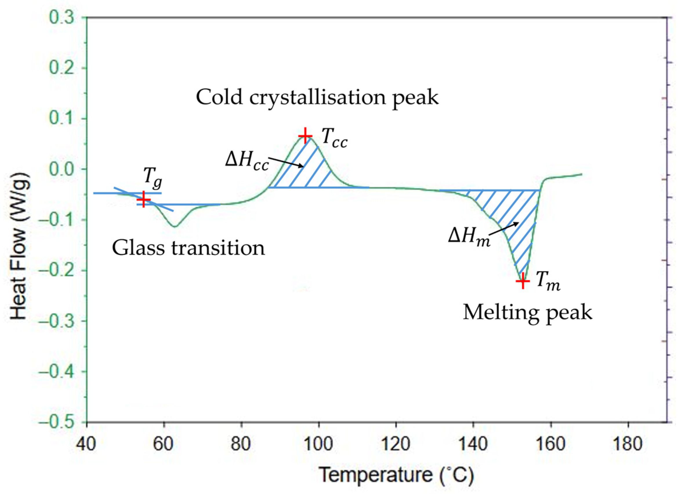
In semi-crystalline thermoplastic SMPs, two essential temperatures are necessary: the glass transition temperature T g (°C) and the melting temperature T m (°C). They define three states for the polymer: at lower temperatures than T g , the material is in its glassy state; between T g and T m , the amorphous part of the material becomes rubbery, which means that the molecules have enough energy for relative movement; above T m , the crystalline phase melts, and the whole material is in an amorphous viscous phase. Two ways of creating crystals within the polymer’s structure are possible: by the slow cooling of the material under its T g , or by cold crystallisation. The latter defines a third temperature, the cold crystallisation temperature T c c (°C), that can be defined between T g and T m and corresponds to a temperature around which the polymer chains gain sufficient mobility to arrange themselves into an ordered crystalline structure. This information can be found on a Differential Scanning Calorimetry (DSC) thermogram (Figure 11). In terms of 4D printing, T g corresponds to the temperature that triggers the shape memory effect, characterised by a drop of enthalpy on a DSC thermogram. T m is the temperature to surpass to print the material by FFF and corresponds to an endothermic peak on the DSC thermogram. The cold crystallisation peak is characterised by an exothermic peak. The amount of crystalline phase compared to the amorphous one is the crystallinity ratio χ v (often expressed as a percentage) defined by the formula below:
χ v = Δ H m Δ H c c Δ H m 0 × 100
where the enthalpy of melting Δ H m (J/kg) corresponding to the energy necessary to melt all of the crystals, and the enthalpy of cold crystallisation Δ H c c (J/kg) corresponding to the energy necessary to create new crystals are obtained by measuring the surface areas under the melting peak and the cold crystallisation peak on a DSC thermogram, respectively (Figure 11). Δ H m 0 corresponds to the melting enthalpy of the fictive 100% crystallised polymer considered. For neat PLA, it is equal to 93.6 J/g according to Solarski et al. [73]. For a filled polymer or a composite, Equation (1) can be balanced by the ratio of filler in the material since crystallinity is inherent of the polymer [90]:
χ v = Δ H m Δ H c c Δ H m 0 × ( 1 τ f ) × 100
where τ f (%) is the ratio in weight of the filler in the polymer. This amount can be measured by Thermogravimetric Analysis (TGA) [90].
Another property that can be measured by DSC, when used in its modulated mode, is the heat capacity C p (J/(kg·K)). At a constant pressure, it corresponds to the heat energy that can be released or absorbed by a unit mass of material [61].
When heated, a material tends to expand or shrink. It is defined by the thermal expansion coefficient α (/K). This property can be characterised by measuring the displacement created by the material under a gradient of temperature. Dynamic Mechanical Analysis (DMA) in compression mode or a dilatometer can be used for this purpose. For anisotropic materials, such as 3D-printed samples, preferential directions might need to be characterised.
For a thermosensitive SMP, another interesting property is the thermal conductivity λ (W/(m·K)), which corresponds to the capacity of the material to conduct heat without any macroscopic movement [91]. For an electrically conductive material, electrical conductivity δ (S/m) can also be defined as the capacity of the material to conduct electricity. It is the inverse of the electrical resistivity ρ (Ω·m):
δ = 1 ρ
Then, the electrical resistance depends on the geometry of the sample considered. The most common formula is for a filament [92]:
R = ρ × L S
where R (Ω) is the electrical resistance, S (m2) is the cross section of the sample through which the electricity is conducted, and L (m) is the length of the sample considered. The electrical resistance can be measured with a multimetre, and is known to vary linearly with the temperature T [93]:
R T = R 0 ( 1 + b T T 0 )
where R 0 (Ω) is the initial electrical resistance measured at the initial temperature T 0 (°C), and b is a thermal coefficient.

4.2. Mechanical Characteristics

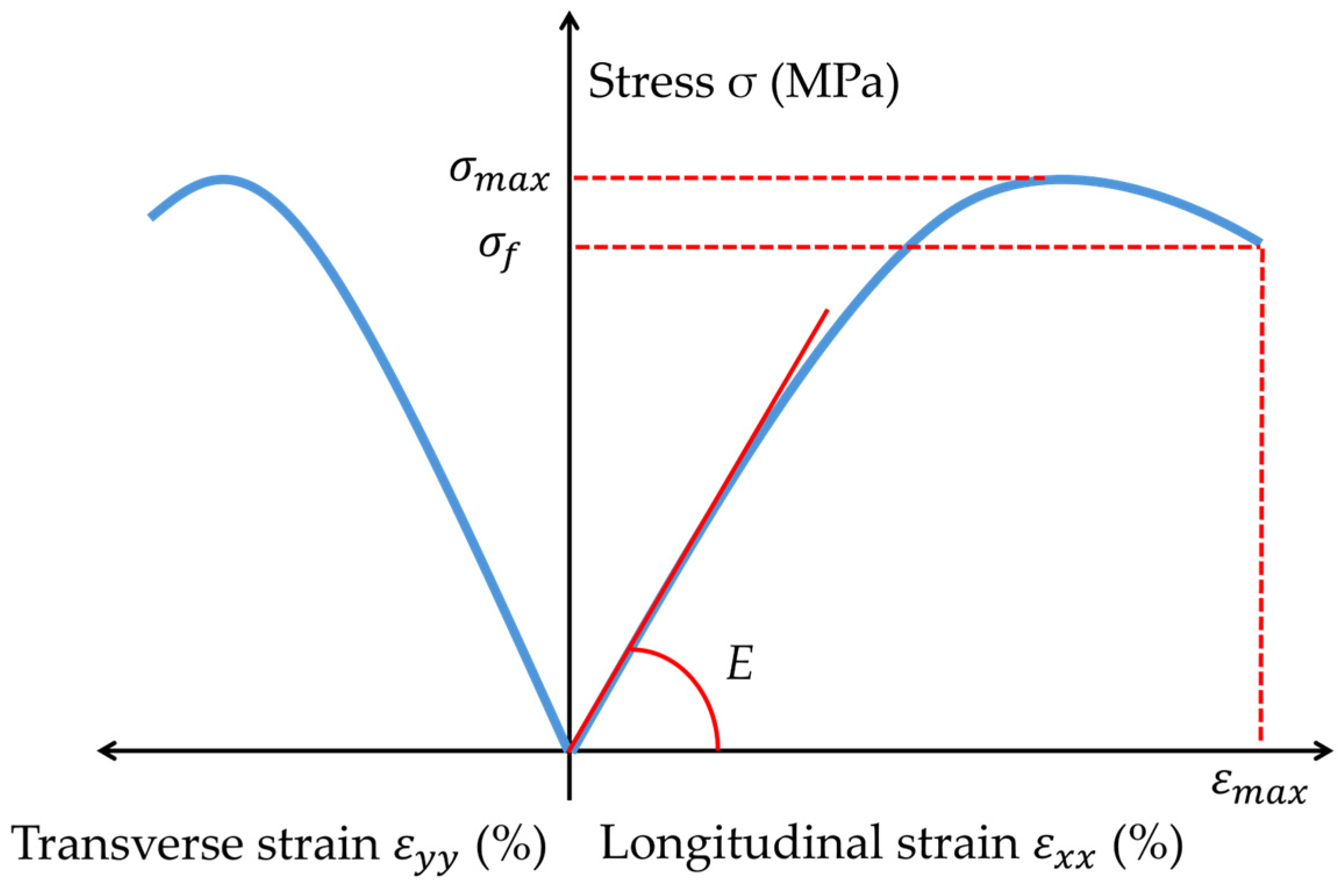
Tensile testing makes it possible to measure the stress σ (MPa) and strain ε (usually expressed as a percentage) experienced by the sample subjected to a longitudinal unidirectional monotonic quasi-static load (Figure 12). The stress is calculated as the ratio of the load applied F (N) and the cross section of the sample tested S (m2):
σ = F S
The strain corresponds to the relative variation in length of the sample:
ε = l l 0 l 0 × 100
where l (mm) is the length of the sample and l 0 (mm) is its initial length. The strain can be measured in the longitudinal length of the sample ε x , or in its transverse length ε y , with the different lengths then being measured in the corresponding direction. In the elastic field, which corresponds to the elastic behaviour of the sample when the strain is reversible and is translated by a linear evolution of the stress–strain curve, the Young’s modulus E and the Poisson ratio ν can be defined. The Young’s modulus reflects the stiffness of the material and is calculated according to the following formula, only true within the elastic field:
E = σ ε
The Poisson ratio is defined as the ratio of the transverse strain ε y and the longitudinal strain ε x . It is defined by the formula, only in the elastic field:
ν = ε y ε x
The mechanical properties of the SMP are highly related to the way it is formulated. Depending on the crystallinity, structure of the polymer, molecular weight, whether plasticisers or couplings agents were added to the formulation or whether it is a blend, its mechanical behaviour can vary from soft elastic plastic to stiff and high-strength plastic [94]. Wang et al. has demonstrated an improvement in the mechanical properties of PLA when adding up to 5.5% of CB in weight to the polymer [72]. Furthermore, when 3D-printed, CB/PLA shows an enhancement of its mechanical properties for up to 12% in weight of CB, before noticing a drop for higher concentrations of CB [82,83].
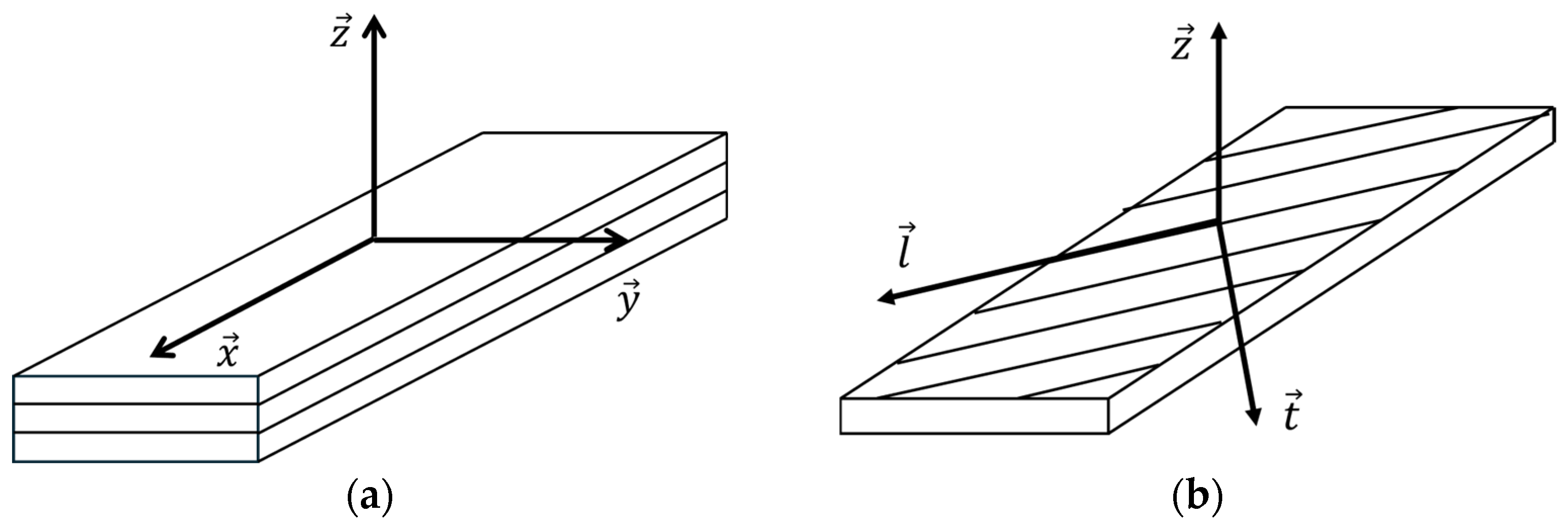
Three-dimensional-printed samples by FFF can be considered as laminated structures, with the layers being plies where the filaments are unidirectionally deposited. It is well-known that the mechanical properties are influenced by the superimposition of plies oriented at multiple preferential directions compared to a single unidirectional layer. In this case, the Classical Laminate Theory (CLT) can be considered [67,95,96] and a coordinate system is defined whether the laminate (Figure 13a) or the layer within it (Figure 13b) is considered. The direction x corresponds to the longitudinal direction of the structure, y to the transverse one, and z is the direction against the layers. In a ply, l follows the direction of the filaments and t defines the perpendicular direction in the plane of the ply.
For a balanced and symmetric laminate in a plane stress state, the CLT makes it possible to predict the mechanical properties depending on the ones of unidirectional laminates [97]. Its behaviour law can be written in the global coordinate system of the laminate when subjected to a unidirectional force along the x axis (Figure 13a):
N x N y N x y M x M y M x y = A 11 A 12 0 0 0 0 A 12 A 22 0 0 0 0 0 0 A 33 0 0 0 0 0 0 D 44 D 45 D 46 0 0 0 D 54 D 55 D 56 0 0 0 D 64 D 65 D 66 × ε x x ε y y γ x y k x k y k x y
where N i is the resultant force and M i is the resultant moment in the i direction in the global coordinate system; ε x x and ε y y are the longitudinal and transverse strains, respectively, γ x y is the distortion, k x and k y are the bending curvatures and k x y is the torsion curvature, and D i j are the bending stiffness coefficients. The coefficients of the extensional stiffness matrix ( A i j ) are determined thanks to the formula:
A i j = k = 1 s t   p l y n b   o f   p l i e s Q i j k × e k
where e k is the thickness of an orthotropic unidirectional ply k, and Q i j k is the coefficient of its stiffness matrix. ( Q i j ) is defined in the Hooke’s law for a single layer at ambient temperature:
σ x σ y τ x y = Q 11 Q 12 Q 13 Q 21 Q 22 Q 23 Q 31 Q 32 Q 33 × ε x ε y γ x y
Considering the local coordinate system of a ply (Figure 13b), the compliance matrix corresponding to the stiffness matrix can be written as follows:
ε l ε t γ l t = 1 E l ν t l E t 0 ν l t E l 1 E t 0 0 0 1 G l t × σ l σ t τ l t
where E i , ε i , σ i are the Young’s modulus, strain and stress along the l or t direction, respectively, γ l t is the distortion, τ l t is the shear stress, G l t is the shear modulus and ν l t and ν t l are the Poisson ratios. To apply the CLT to a laminate, four independent parameters are therefore needed: E l , E t , ν l t and G l t . A sample with only unidirectional filaments along the direction l , also called 0° sample, gives the Young’s modulus and the Poisson ratio:
E l = E x 0
ν l t = ν x y 0
with E x 0 the Young’s modulus and ν x y 0 the Poisson ratio of a 0° sample. A sample with filaments perpendicular to the direction of the force, also called 90° sample, gives the Young’s modulus along the direction t :
E t = E x 90
with E x 90 the Young’s modulus of a 90° sample. Finally, G l t can be calculated with a sample whose filaments are alternatively at +45° or −45° compared to the direction l , also called a ±45° sample:
1 2 σ x ± 45 = G l t ε x ± 45 ε y ± 45
with σ x ± 45 the stress, and ε x ± 45 and ε y ± 45 the longitudinal and transverse strains, respectively, of a ±45° sample. Finally, the following formula must be verified:
ν l t E l = ν t l E t
with ν t l the Poisson ratio of a 90° sample:
ν t l = ν x y 90 °
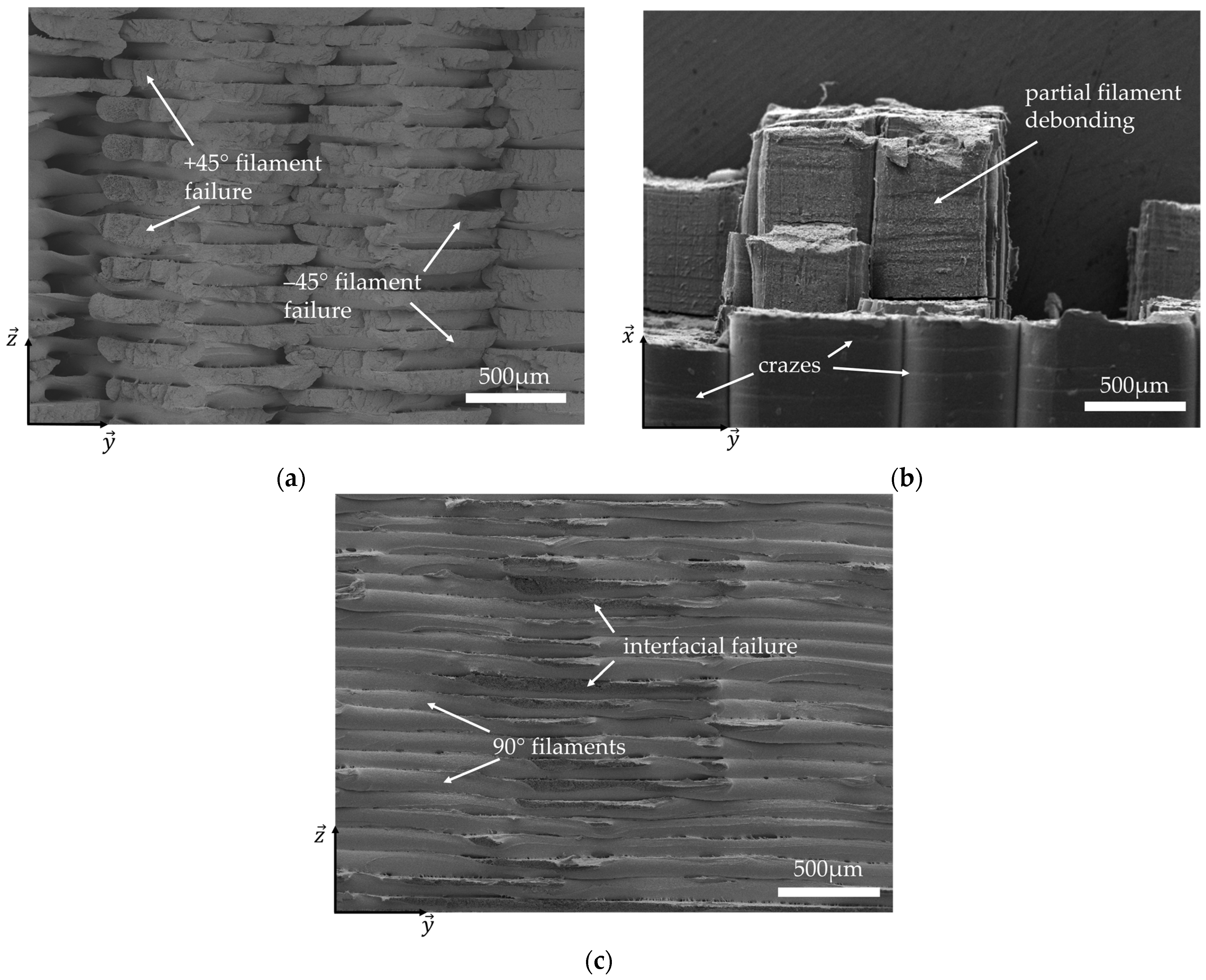
After the failure of the sample in tensile testing, an analysis of the fracture surface is often conducted to determine the damage mechanisms. Scanning Electron Microscopy (SEM) can be used for this purpose. The macrostructure of the samples can be observed with the printed filaments clearly visible. Voids between the filaments can be seen, inherent to the method of FFF printing [96]. Three mechanisms of failure can be witnessed: the breaking of a filament (Figure 14a); a debonding between two superimposed layers (Figure 14b); and the debonding between two adjacent filaments within the same layer (Figure 14c) [98,99].

4.3. Recovery Ratio

To evaluate the shape memory properties of a device, several parameters are defined. The recovery ratio represents the percentage of recovery the sample achieves, 100% meaning that it entirely returned to its permanent shape. It depends on the motion considered but mainly consists of a comparison between the angle the sample forms in its temporary shape with the target angle of the permanent shape. For instance, Wang et al. define the formula as the following, for a target angle of 180°, or π rad [14]:
R E C = φ d φ p π φ p × 100
where φ d is the angle achieved after triggering the shape memory effect and φ p is the programmed angle. They are illustrated in Figure 15.
The recovery of the sample is performed at a certain speed, which defines the recovery rate:
V R E C = d R E C d t
For thermosensitive polymers, it is necessary to define two temperatures for the shape memory effect: the programming temperature T p which corresponds to the temperature at which the programming step is performed; and the triggering temperature T t which corresponds to the temperature at which the specimen is heated to trigger the shape memory effect. Several studies have investigated the influence of the triggering temperature on the recovery ratio. Barletta et al. [35] show that for a 3D-printed by FFF auxetic structure made of PLA, the higher the triggering temperature, the faster the specimen comes back to its permanent shape and with a better recovery ratio. It is explained by the fact that the shape memory effect is triggered at the glass transition temperature; therefore, when the triggering temperature is high, the glass transition temperature is reached faster. However, some authors counterintuitively show that a programming step performed at ambient temperature and at a very slow rate also increases the recovery ratio, even though the programming step is known to have to be performed at the glass transition temperature [35,101]. Other than the programming and triggering temperature, some authors suggest that the holding time of the temporary shape and the deformation rate during the programming step influence the recovery performance of the structure [102,103].
Table 2 summarises different thermosensitive Shape Memory Polymers manufactured by FFF and their key performance properties. However, 3D printing by FFF is not a conventional manufacturing method and creates new challenges in itself. Indeed, the printing parameters have a high impact on the properties of the resulting specimens, as suggested in Table 2, and described in the following section.

5. Response of 4D-Printed Shape Memory Polymers

5.1. Influence of the Printing Parameters

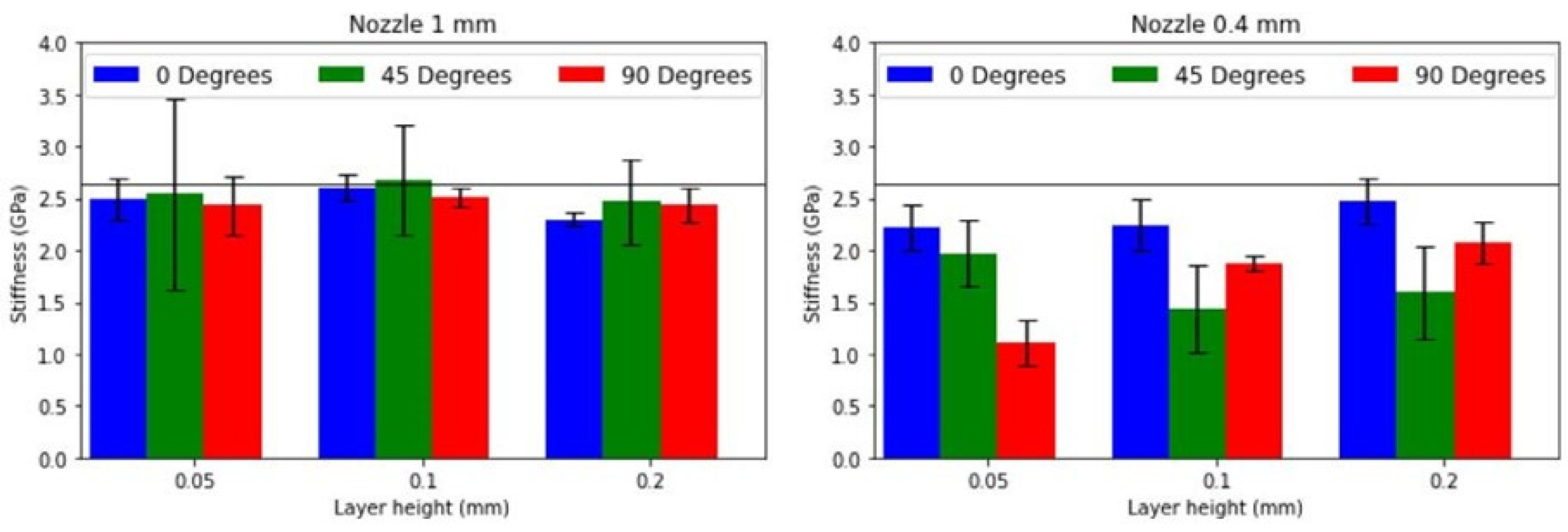
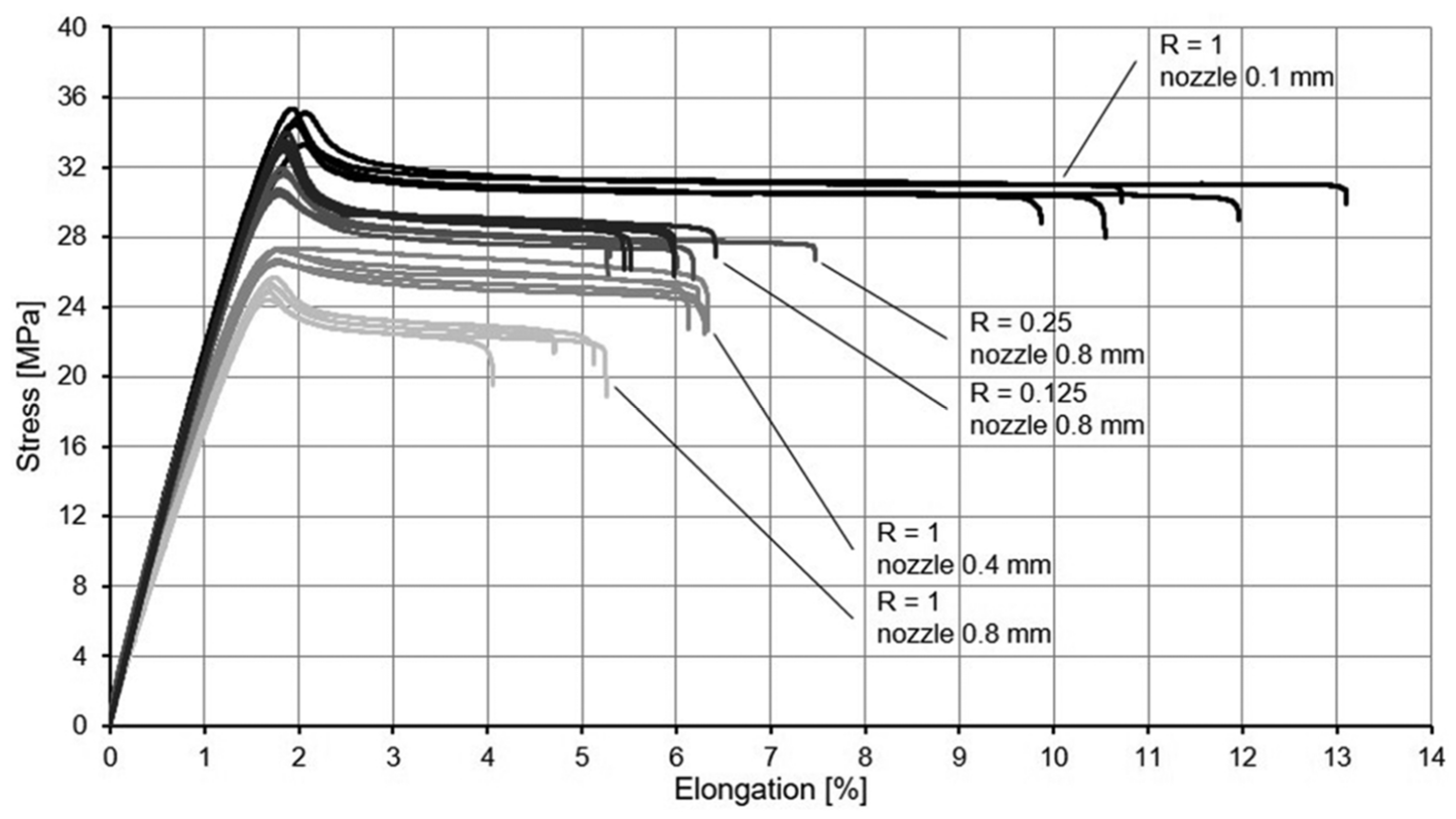
Various printing parameters are to consider in the manufacturing of a specimen by FFF. In the literature, many authors have shown their impact on the properties of the samples. For a conventional laminate structure, it is well-known that the direction of alignment of the fibres highly influences the mechanical results [100]. In the case of 3D printing by FFF, it has already been suggested that the Classical Laminate Theory could be considered with specimens printed with different raster angles. The printing deposition creates filaments that could be assimilated to continuous fibres. It has indeed been reported in the literature that the printing direction influences the mechanical properties of the resulting specimens [76,78,98,100]. In addition, the nozzle diameter and the layer height have been shown to play an important role in the mechanical properties. Fischer et al. [106] and Delbart et al. [76] demonstrate the impact of the nozzle diameter and layer height on the mechanical properties. Indeed, Delbart et al. [76] highlight that the CB/PLA samples printed at 0° with a nozzle of 1 mm and a layer height of 0.05 mm showcase the best mechanical properties (Figure 16). Otherwise, Fischer et al. [106] explain that the smallest nozzle diameter and the thinnest layer height provide better results for ±45° ABS specimens (Figure 17). Both studies indicate that the optimal configuration exhibits the lowest porosity. Nonetheless, they clearly demonstrate the various possibilities offered by 3D printing by FFF by adjusting printing parameters, thereby highlighting the complexity of mastering this manufacturing process, as well as the numerous opportunities it presents.
Furthermore, the nozzle temperature, the printing speed and the layer height are also shown to have an impact not only on tensile mechanical properties, but also on the compression test performed on an auxetic structure [35]. Nadernezhad et al. [98] increased the layer height of their samples, leading to a change in the damage mechanisms observed. At a lower layer height, fewer bonds were created between the filaments, therefore leading to a failure of these interfaces under mechanical loading. On the other hand, at higher layer height, voids were too large for interfaces to form between filaments, leading to failure governed by filament breakage.
Concerning conductive polymers, the printing parameters can have an influence on the propagation of electricity within the 3D-printed structure [65]. For instance, the raster angle has a significant impact on the electrical resistivity. The lowest resistivity is obtained for a 0° sample as the 3D-printed filaments are deposited along the path followed by the electricity (Table 3). However, an alternation of different raster angles within one sample can also improve the resistivity, as highlighted by Truman et al. [80], and confirmed by the [06/±455/905]S samples in Table 3. Tirado-Garcia et al. [74] go further by heating the samples by Joule effect, and demonstrating that 0° and ±45° samples are able to reach higher temperatures than 90° samples. The role of the layer height is also reported to impact the resistivity [25,75].
In the case of PLA filled with carbon nanotubes, Nadernezhad et al. [98] studied the influence of the infill density, raster angle and layer height on the thermo-mechanical properties of their samples, considering the coefficient of thermal expansion in addition to the mechanical properties. They explain the role of the printing parameters on the residual stress, or pre-strain, induced during the manufacturing. Several authors are interested in this as pre-strain gives control over the programming step, when this step is directly inherited from the printing process. For instance, Van Manen et al. [47] considered the nozzle temperature and layer height, and Barletta et al. [35] also considered the printing speed. The latter has a direct understandable link with the pre-strain as this directly results from the pulling of the material through the nozzle and along the printing path. The greater the printing speed, the more the molecules will be pulled apart by the printing process, therefore enhancing the pre-strain.
In terms of 4D printing, the printing parameters are also shown to directly impact the recovery ratio of the shape memory effect. Wang et al. [14] studied the influence of the nozzle temperature, layer thickness and sample thickness on the recovery ratio of their structure as well as the speed at which it recovers. The nozzle temperature and the thickness of the sample do not seem to impact the recovery ratio, whereas the fastest recovery rate is found for the hottest nozzle temperature (220 °C) and the thinnest sample (1 mm) (Figure 18a,b). For the layer thickness, the best recovery ratio is found for the sample that recovers the slowest (150 µm), whereas a thicker layer height of 300 µm conversely demonstrates a faster recovery but at a lower ratio (Figure 18c). Zolfagharian et al. [107] used different numbers of layers and printing patterns to achieve different actuations, also by combining the bilayer effect and variant raster angles within the same sample.
Four-dimensional printing presents various opportunities due to the manufacturing method that plays a key role in the resulting device, as well as the material used. It opens the way to many different conceptions for the same actuation, depending on the point of view. However, the intricacies implied by using shape memory materials also bring a fair number of challenges.

5.2. Interdependencies of the Properties

The previous sections demonstrated the complexity of 4D printing due to the manufacturing method and the materials used. As a matter of fact, triggering the actuation of a 4D-printed device makes it necessary to take into account several fields implied in the resulting motion. For instance, electrically conductive thermosensitive SMPs combine electrical, thermal and mechanical properties, and the subsequent behaviour is due to the couplings between them. The link between the strain and the evolution of the resistivity has been investigated in the literature. Khan and Singh [64] measured the conductivity of a CB/SMP resin in the transverse direction during a tensile test and a compression test. They highlighted the need to control the input power when Joule heating a conductive device, as the conductivity changes with the strain. This coupling was also demonstrated for CB/PLA [100]. This kind of research could be applied to sensors capable of measuring the strain by monitoring the resistivity in a component.
The control of the temperature of an electrically conductive device led several authors to consider the effect of Joule heating on the temperature of their specimens [30,65,79,93], therefore verifying the linear law governing it.
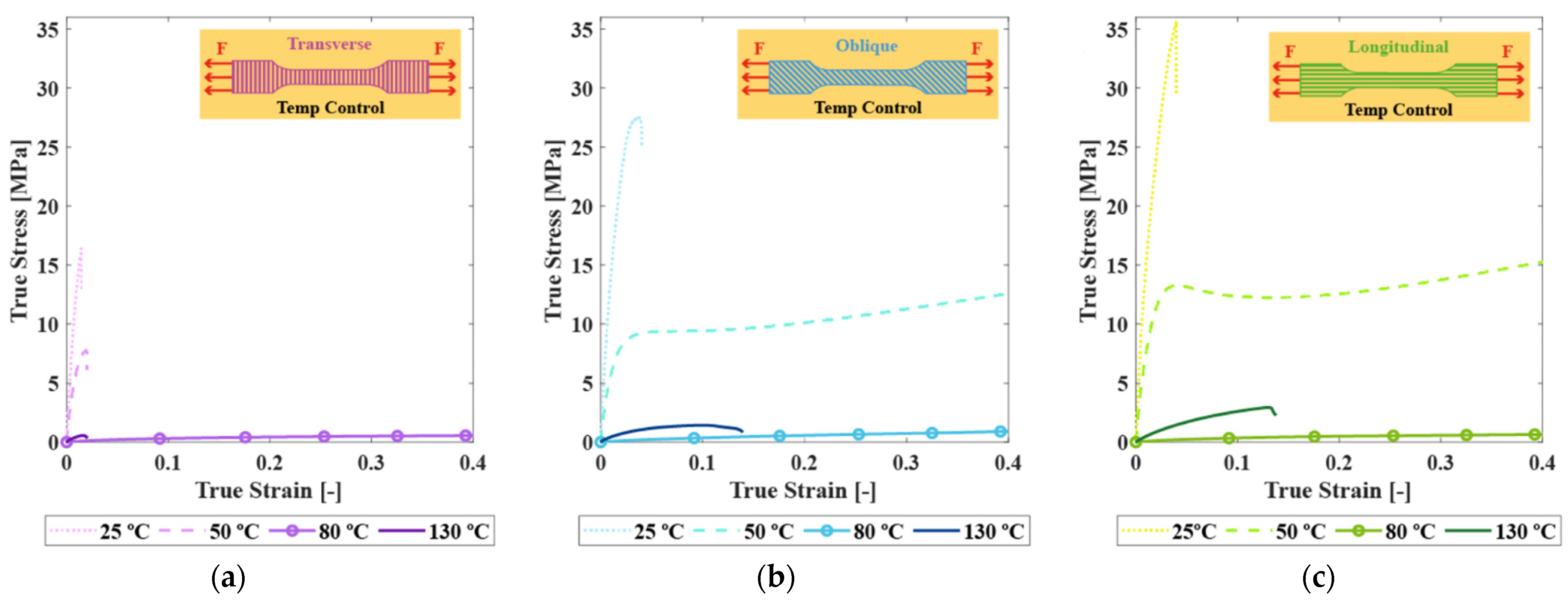
In terms of thermo-mechanical coupling of 3D-printed by FFF CB/PLA specimens, Crespo-Miguel et al. [78] studied different raster angles under tensile testing in environmental chambers to analyse the effect of various temperatures on the behaviour of the material (Figure 19). This study highlights the evolution of the mechanical behaviour of the CB/PLA with its temperature, which is directly linked with the phase transition that happens around its glass transition temperature. However, thermoelectric materials characterisation is a challenging task that depends not only on the current temperature but also on the entire thermal history. Studies demonstrate inherent differences between oven heating and Joule heating [76], suggesting that they are not equivalent due to differences in thermal inertia. The electrical network, and, therefore, the multifunctional properties of the material, are better preserved by Joule heating rather than by oven heating due to the faster heating rate. These results directly emphasise the difficulty of studying such a material due to the experimental challenges and limitations of decoupling the different properties that are at stake.
In terms of electro-mechanical coupling, the samples are tensile-tested with or without monitoring of the electrical resistance. For instance, Crespo-Miguel et al. [79] measured the electrical resistivity of a filament of CB/PLA subjected to tensile testing before and after extrusion (Figure 20a), highlighting the effect of FFF manufacturing on the material. In a second study [79], they went further by considering tensile testing of samples after they had been subjected to Joule heating (Figure 20b). An increase in the mechanical properties can be seen with a rise in the voltage applied, up to 60 V, and a loss of mechanical properties is witnessed for 90 V. They explain these results by the evolution of the macrostructure of the samples, influenced by Joule heating on the void content. Another study [99] on the evolution of electrical resistance with applied voltage suggests that changes in the microstructure of the material might have influenced the mechanical properties. Tirado-Garcia et al. [74] studied the evolution of electrical resistance during a tensile test of a 0° sample (Figure 20c), and other raster angles were also considered in a different study [94]. Once again, these papers show the complexity of studying interdependent properties. The experimental setups are challenging to put in place, and the manufacturing method implies a strong dependency of the results on the printing parameters.

5.3. Durability

Even though most of the 4D-printed devices made of SMPs are non-reversible when it comes to their motion, the repeated use of such structures has been considered in the literature. Cyclic Joule heating has been studied in various configurations. Snyder et al. [108] considered a woven glass/carbon fibre on which they 3D-printed a self-healing thermosensitive thermoplastic. To use its ability, interlayers made of resistive heaters are embedded within the structure. This way, 100 cycles of Joule heating are performed to study the self-healing ability of the material after delamination.
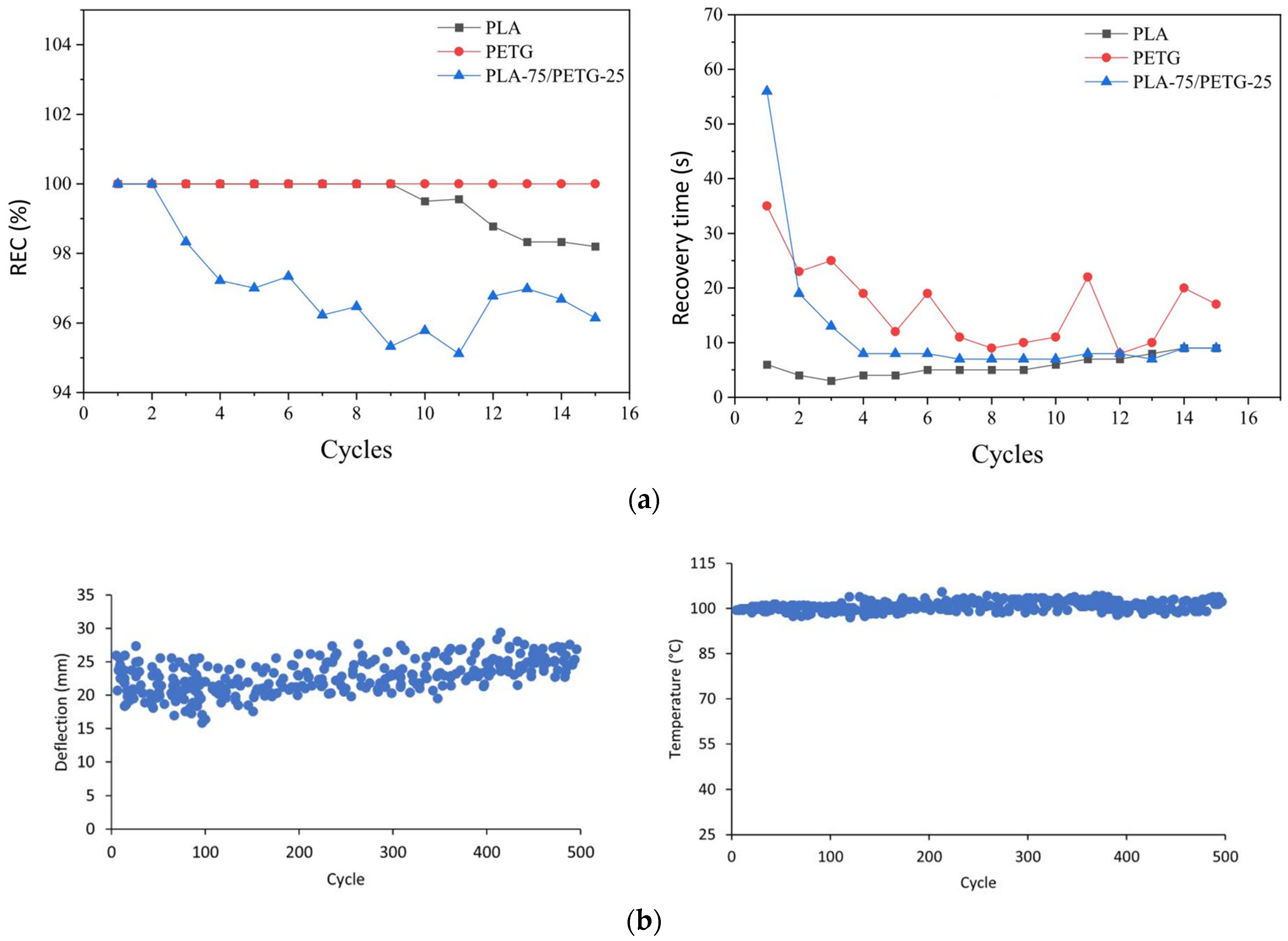
Bouguermouh et al. [104] compared the deployment cycles of specimens made of PLA, PETG or both over 15 repetitions (Figure 21a). The PLA sample demonstrated a recovery ratio of 100% over the nine first cycles before its performances degraded, with a constant deployment speed. The best recovery ratio was obtained for the PETG specimen that kept a recovery of a 100% while being deployed slightly faster with the increasing number of cycles.
Lalegani Dezaki et al. [30] used SMA wires to create a reversible hinge. They studied 500 cycles of Joule heating programmed thanks to a switch, and the device did not show any evidence of fatigue since its deflection, and the temperature stayed constant throughout the experiment (Figure 21b).
On the other hand, mechanical durability is assessed with various types of experiments in the literature. Cyclic mechanical tensile testing is often performed, with the monitoring of electrical resistance [94], at different temperatures [103], with the influence of environmental factors such as humidity [104], or with a Dynamic Mechanical Analysis machine [96].
Durability also involves environmental factors such as humidity or chemical exposure [109]. For instance, SMPs are considered for space applications thanks to their large deformability and high strength-to-weight ratio. But their behaviour in the extreme space conditions is under study [99,110,111]. Furthermore, thermal fatigue is a key challenge as it was demonstrated that the successive heating of conductive SMPs led to particle migration and the evolution of the conductive pathways [65,75]. The complexity of this research field and the multiplicity of factors involved make it a challenging question to study, with the scarce literature on this matter. These studies demonstrate the difficulty of the intricacies this type of material presents, with the additional challenges added by 3D printing.

5.4. Numerical Modelling

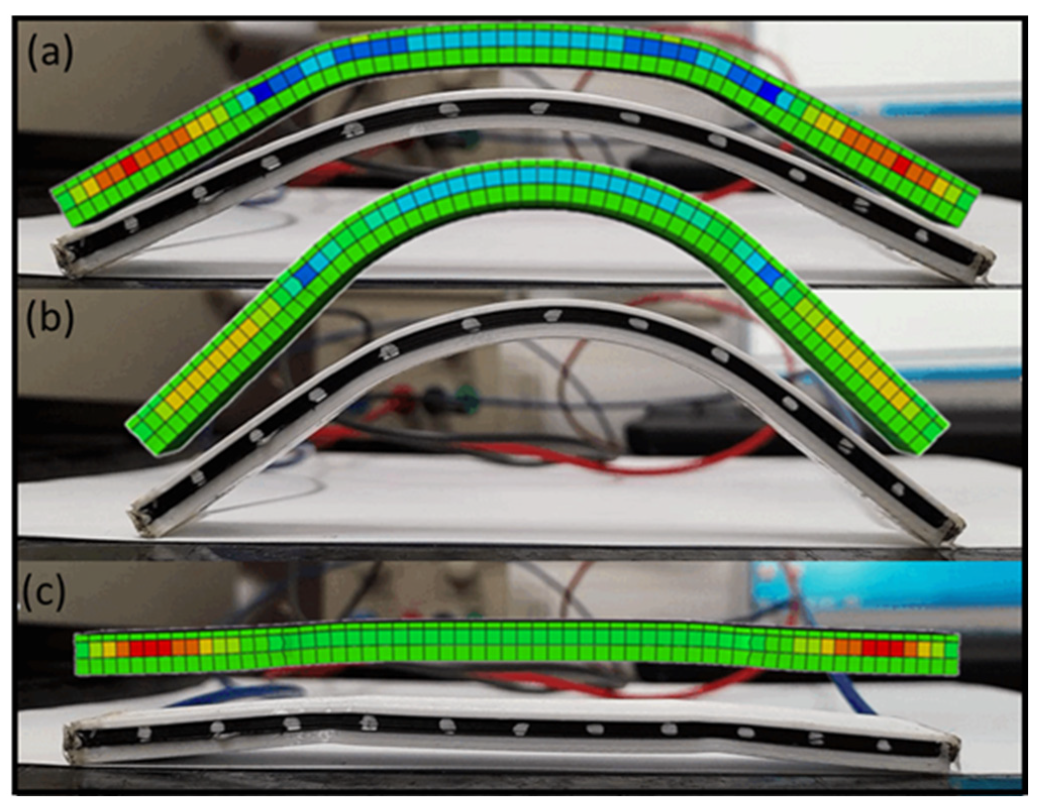
Given the intricate interplay of electro, magnetic, photo, thermal, and mechanical responses in 4D printing, modelling is crucial for understanding the physics behind the mechanical behaviour during different programming and actuation stages. The Finite Element Method (FEM) has been effectively used in the past to design actuators for soft robotics [112] (Figure 22), morphing structures [17,48], energy absorption devices [113]. It has the advantages of being able to compare experimental data, such as the movement of the device or the force deployed, with a numerical model working with different inputs, pressure or temperature, for instance. An optimisation of the topology and motion of the actuator can be performed, based on its design, to predict the resulting force. Homogenised multi-scale mechanical approaches are developed in the literature [114,115,116], taking into account the printing parameters with the modelling of the printed filaments. The distribution of voids and defects are considered [117], enabling the optimisation of the printing parameters and the overall manufacturing architecture of the device. The internal stress induced by the manufacturing method can also be predicted [118,119], but these models are very costly computationally wise.
The overall trends and motion of the actuator can therefore be predicted by FEM models, but they lack accuracy for engineering applications [17]. A strong experimental database is needed, and the scarce experimental data on the plastic response of polymers, especially around and above the glass transition temperature, involved in the response of the material for large deformations, is the main limitation of FEM when internal triggers such as electricity or magnetic fields are at stake, therefore limiting the modelling of temperature-dependent phenomenon. Future work should focus on obtaining better temperature gradients by fine-tuning the multi-scale models used and strengthening the experimental database by characterising electro-thermo-mechanical properties of materials.

6. Conclusions

4D printing is the technology that combines additive manufacturing and smart materials to create a transformation independent of any motor or human action. Various 3D printing methods are available on the market, but Fused Filament Fabrication is chosen for its versatility, customisability and ease of use. The materials used can be chosen to be combined for their specific properties, such as the bilayer effect or their shape memory ability. These latter can be polymers, alloys or ceramics. Shape Memory Polymers have gathered considerable attention due to their affordability and variety of triggering stimuli. In particular, thermosensitive SMPs are widely studied, but mainly heated by an external source. Hence, there is an interest in studying polymers reinforced with conductive fillers to provide improved mechanical performances as well as internal Joule heating. For instance, CB/PLA is an off-the-shelf, ready-to-use, electrically conductive thermosensitive SMP. However, the challenge of manufacturing conductive SMPs lies in the content and dispersion of conductive fillers, which can directly impact the conductive pathway and the mechanical properties.
Nonetheless, such materials present their fair share of challenges due to the coupling of their electrical, thermal and mechanical properties. First, the properties of the resulting samples have been shown to be highly influenced by the printing parameters. Most importantly, understanding the evolution of electrical resistance is essential as it governs the Joule heating process. In the literature, the influence of the processing parameters has been studied, but mainly one at a time, which opens the necessity for comprehensive studies. On the other hand, understanding the electro-thermal coupling is essential for controlling the temperature field resulting from the Joule heating. Furthermore, the question of a repeated use of such a material in a potential application has not been considered to our knowledge.
When it comes to the mechanical properties, although the influence of the printing direction has been established, the link between the electrical and the mechanical properties of a conductive SMP has only been shallowly introduced. From the perspective of a potential application, the correct printing parameters need to be selected to improve the mechanical and electrical properties. In addition, very little is known about the evolution of the damages within a 3D-printed sample even though some studies have started investigating this matter.
Various applications have been designed by 4D printing in fields such as soft robotics, healthcare or aerospace. SMPs are starting to establish their own place thanks to their affordability and versatility; however, they are often displayed as proofs of concept. In addition, to compensate an external heat trigger for a thermosensitive material, complex designs with embedded wires or resistive heaters are proposed as including ovens in a structure is not efficient. To this end, conductive thermosensitive SMPs are studied as a solution with an inner and remote electrical actuation.
However, a key limitation of 4D printing is its generally low capacity for load bearing, which arises from the inherent trade-off between compliance and stiffness in traditional structural materials. Shapeshifting structures require enough flexibility to handle large rotations and deformations, yet this can conflict with the need for structural strength and load-bearing ability. In the literature, it is often approached with the demonstration of the actuator lifting one weight. When a continuous measurement of the force deployed is studied, it is limited by the geometry and dimensions of the sample, or the mechanisms responsible for the motion are not only the shape memory behaviour, but also the bilayer effect. Employing soft polymers or adding cuts and holes in stiff layers increases hinge flexibility, enabling significant deformation and rotation. However, these approaches often do not meet the load-bearing requirements for structural applications. To overcome this limitation, innovative methods have been devised to combine the advantages of shape-changing materials with structural elements, such as metals or composites. This involves integrating hybrid materials, such as Shape Memory Alloys or composites, which include both compliant and rigid components.
Finally, the recovery ratio being a key parameter to measure the successful deployment of an actuator, its evolution depending on the programming temperature or the triggering temperature is partially reported in the literature. And for a repeated use of the prototype, the results highly depend on the configuration and material. Lastly, the main drawback of SMPs is their one-shot deployment ability.

Author Contributions

Investigation, L.R.; writing—original draft preparation, L.R.; writing—review and editing, F.T., T.-Q.T.-H. and F.M.-H. All authors have read and agreed to the published version of the manuscript.

Funding

This work was supported by the Defense Innovation Agency (AID) of the French Ministry of the Armed Forces through the grant [AID-2021 65 0045].

Institutional Review Board Statement

Not applicable.

Informed Consent Statement

Not applicable.

Data Availability Statement

Not applicable.

Acknowledgments

The contribution of Robin Delbart in numerical modelling and filler dispersion is kindly acknowledged.

Conflicts of Interest

The authors declare no conflicts of interest.

References

  1. Ryan, K.R.; Down, M.P.; Banks, C.E. Future of additive manufacturing: Overview of 4D and 3D printed smart and advanced materials and their applications. Chem. Eng. J. 2021, 403, 126162. [Google Scholar] [CrossRef]
  2. Margoy, D.; Gouzman, I.; Grossman, E.; Bolker, A.; Eliaz, N.; Verker, R. Epoxy-based shape memory composite for space applications. Acta Astronaut. 2021, 178, 908–919. [Google Scholar] [CrossRef]
  3. Khoo, Z.X.; Teoh, J.E.M.; Liu, Y.; Chua, C.K.; Yang, S.; An, J.; Leong, K.F.; Yeong, W.Y. 3D printing of smart materials: A review on recent progresses in 4D printing. Virtual Phys. Prototyp. 2015, 10, 103–122. [Google Scholar] [CrossRef]
  4. Delbart, R.; Roumy, L.; Harcourt, M.; Robert, C.; Touchard, F.; Truong-Hoang, T.Q.; Martínez-Hergueta, F. 4D-printed composite actuators. In Additive Manufacturing of Polymer-Based Composite Materials; Elsevier: Amsterdam, The Netherlands, 2024; pp. 147–183. [Google Scholar] [CrossRef]
  5. Ren, L.; Li, B.; Song, Z.; Liu, Q.; Ren, L.; Zhou, X. Bioinspired fiber-regulated composite with tunable permanent shape and shape memory properties via 3d magnetic printing. Compos. Part B Eng. 2019, 164, 458–466. [Google Scholar] [CrossRef]
  6. Riley, K.S.; Ang, K.J.; Martin, K.A.; Chan, W.K.; Faber, J.A.; Arrieta, A.F. Encoding multiple permanent shapes in 3D printed structures. Mater. Des. 2020, 194, 108888. [Google Scholar] [CrossRef]
  7. Ge, Q.; Sakhaei, A.H.; Lee, H.; Dunn, C.K.; Fang, N.X.; Dunn, M.L. Multimaterial 4D Printing with Tailorable Shape Memory Polymers. Sci. Rep. 2016, 6, 31110. [Google Scholar] [CrossRef]
  8. Lendlein, A.; Jiang, H.; Jünger, O.; Langer, R. Light-induced shape-memory polymers. Nature 2005, 434, 879–882. [Google Scholar] [CrossRef]
  9. Schmidt, A.M. Electromagnetic Activation of Shape Memory Polymer Networks Containing Magnetic Nanoparticles. Macromol. Rapid Commun. 2006, 27, 1168–1172. [Google Scholar] [CrossRef]
  10. Josselin, M.; Di Cesare, N.; Castro, M.; Colinart, T.; Scarpa, F.; Le Duigou, A. Hygro-thermal coupling on 4D-printed biocomposites as key for meteosensitive shape-changing materials. Virtual Phys. Prototyp. 2024, 19, e2335233. [Google Scholar] [CrossRef]
  11. Dong, K.; Panahi-Sarmad, M.; Cui, Z.; Huang, X.; Xiao, X. Electro-induced shape memory effect of 4D printed auxetic composite using PLA/TPU/CNT filament embedded synergistically with continuous carbon fiber: A theoretical & experimental analysis. Compos. Part B Eng. 2021, 220, 108994. [Google Scholar] [CrossRef]
  12. Demoly, F.; Dunn, M.L.; Wood, K.L.; Qi, H.J.; André, J.-C. The status, barriers, challenges, and future in design for 4D printing. Mater. Des. 2021, 212, 110193. [Google Scholar] [CrossRef]
  13. Orellana, J.; Moreno-Villoslada, I.; Bose, R.K.; Picchioni, F.; Flores, M.E.; Araya-Hermosilla, R. Self-Healing Polymer Nanocomposite Materials by Joule Effect. Polymers 2021, 13, 649. [Google Scholar] [CrossRef]
  14. Wang, J.; Wang, Z.; Song, Z.; Ren, L.; Liu, Q.; Ren, L. Biomimetic Shape–Color Double-Responsive 4D Printing. Adv. Mater. Technol. 2019, 4, 1900293. [Google Scholar] [CrossRef]
  15. Dimassi, S.; Demoly, F.; Cruz, C.; Qi, H.J.; Kim, K.-Y.; André, J.-C.; Gomes, S. An ontology-based framework to formalize and represent 4D printing knowledge in design. Comput. Ind. 2021, 126, 103374. [Google Scholar] [CrossRef]
  16. Wischke, C.; Lendlein, A. Shape-Memory Polymers as Drug Carriers—A Multifunctional System. Pharm. Res. 2010, 27, 527–529. [Google Scholar] [CrossRef]
  17. Delbart, R.; Robert, C.; Truong Hoang, T.Q.; Martinez-Hergueta, F. Development of an electro-thermo-mechanical 4D printed multi-shape smart actuator: Experiments and simulation. Compos. Part Appl. Sci. Manuf. 2024, 186, 108381. [Google Scholar] [CrossRef]
  18. De Kergariou, C.; Le Duigou, A.; Perriman, A.; Scarpa, F. Design space and manufacturing of programmable 4D printed continuous flax fibre polylactic acid composite hygromorphs. Mater. Des. 2023, 225, 111472. [Google Scholar] [CrossRef]
  19. De Kergariou, C.; Demoly, F.; Perriman, A.; Le Duigou, A.; Scarpa, F. The Design of 4D-Printed Hygromorphs: State-of-the-Art and Future Challenges. Adv. Funct. Mater. 2023, 33, 2210353. [Google Scholar] [CrossRef]
  20. Le Duigou, A.; Chabaud, G.; Scarpa, F.; Castro, M. Bioinspired Electro-Thermo-Hygro Reversible Shape-Changing Materials by 4D Printing. Adv. Funct. Mater. 2019, 29, 1903280. [Google Scholar] [CrossRef]
  21. Touchard, F.; Sarasini, F. (Eds.) Additive Manufacturing of Polymer-Based Composite Materials; Elsevier: Amsterdam, The Netherlands, 2024. [Google Scholar] [CrossRef]
  22. Liu, G.; Zhang, X.; Lu, X.; Zhao, Y.; Zhou, Z.; Xu, J.; Yin, J.; Tang, T.; Wang, P.; Yi, S.; et al. 4D Additive–Subtractive Manufacturing of Shape Memory Ceramics. Adv. Mater. 2023, 35, 2302108. [Google Scholar] [CrossRef]
  23. Milleret, A.; Laitinen, V.; Ullakko, K.; Fenineche, N.; Attallah, M.M. Laser powder bed fusion of (14 M) Ni-Mn-Ga magnetic shape memory alloy lattices. Addit. Manuf. 2022, 60, 103231. [Google Scholar] [CrossRef]
  24. Holman, H.; Kavarana, M.N.; Rajab, T.K. Smart materials in cardiovascular implants: Shape memory alloys and shape memory polymers. Artif. Organs 2021, 45, 454–463. [Google Scholar] [CrossRef]
  25. Abdalla, A.; Hamzah, H.H.; Keattch, O.; Covill, D.; Patel, B.A. Augmentation of conductive pathways in carbon black/PLA 3D-printed electrodes achieved through varying printing parameters. Electrochim. Acta 2020, 354, 136618. [Google Scholar] [CrossRef]
  26. Junpha, J.; Wisitsoraat, A.; Prathumwan, R.; Chaengsawang, W.; Khomungkhun, K.; Subannajui, K. Electronic tongue and cyclic voltammetric sensors based on carbon nanotube/polylactic composites fabricated by fused deposition modelling 3D printing. Mater. Sci. Eng. C 2020, 117, 111319. [Google Scholar] [CrossRef]
  27. Mitchell, A.; Lafont, U.; Hołyńska, M.; Semprimoschnig, C. Additive manufacturing—A review of 4D printing and future applications. Addit. Manuf. 2018, 24, 606–626. [Google Scholar] [CrossRef]
  28. Decroly, G.; Toncheva, A.; Blanc, L.; Raquez, J.-M.; Lessinnes, T.; Delchambre, A.; Lambert, P. Programmable Stimuli-Responsive Actuators for Complex Motions in Soft Robotics: Concept, Design and Challenges. Actuators 2020, 9, 131. [Google Scholar] [CrossRef]
  29. Zolfagharian, A.; Kaynak, A.; Kouzani, A. Closed-loop 4D-printed soft robots. Mater. Des. 2020, 188, 108411. [Google Scholar] [CrossRef]
  30. Lalegani Dezaki, M.; Bodaghi, M.; Serjouei, A.; Afazov, S.; Zolfagharian, A. Adaptive reversible composite-based shape memory alloy soft actuators. Sens. Actuators Phys. 2022, 345, 113779. [Google Scholar] [CrossRef]
  31. Yang, Y.; Wang, Y.; Yao, T.; Feng, X. A flexible carbon fibre-based electrothermal film for fast actuation of shape memory alloy sheets. Smart Mater. Struct. 2022, 31, 045019. [Google Scholar] [CrossRef]
  32. Zolfagharian, A.; Lakhi, M.; Ranjbar, S.; Tadesse, Y.; Bodaghi, M. 3D printing non-assembly compliant joints for soft robotics. Results Eng. 2022, 15, 100558. [Google Scholar] [CrossRef]
  33. Zhang, Z.; Demir, K.G.; Gu, G.X. Developments in 4D-printing: A review on current smart materials, technologies, and applications. Int. J. Smart Nano Mater. 2019, 10, 205–224. [Google Scholar] [CrossRef]
  34. Yamamura, S.; Iwase, E. Hybrid hinge structure with elastic hinge on self-folding of 4D printing using a fused deposition modeling 3D printer. Mater. Des. 2021, 203, 109605. [Google Scholar] [CrossRef]
  35. Barletta, M.; Gisario, A.; Mehrpouya, M. 4D printing of shape memory polylactic acid (PLA) components: Investigating the role of the operational parameters in fused deposition modelling (FDM). J. Manuf. Process. 2021, 61, 473–480. [Google Scholar] [CrossRef]
  36. Akbari, S.; Sakhaei, A.H.; Kowsari, K.; Yang, B.; Serjouei, A.; Yuanfang, Z.; Ge, Q. Enhanced multimaterial 4D printing with active hinges. Smart Mater. Struct. 2018, 27, 065027. [Google Scholar] [CrossRef]
  37. Liu, Y.; Zhang, W.; Zhang, F.; Leng, J.; Pei, S.; Wang, L.; Jia, X.; Cotton, C.; Sun, B.; Chou, T.-W. Microstructural design for enhanced shape memory behavior of 4D printed composites based on carbon nanotube/polylactic acid filament. Compos. Sci. Technol. 2019, 181, 107692. [Google Scholar] [CrossRef]
  38. Wang, W.; Li, C.; Cho, M.; Ahn, S.-H. Soft Tendril-Inspired Grippers: Shape Morphing of Programmable Polymer–Paper Bilayer Composites. ACS Appl. Mater. Interfaces 2018, 10, 10419–10427. [Google Scholar] [CrossRef]
  39. Smirnov, A.; Terekhina, S.; Tarasova, T.; Hattali, L.; Grigoriev, S. From the development of low-cost filament to 3D printing ceramic parts obtained by fused filament fabrication. Int. J. Adv. Manuf. Technol. 2023, 128, 511–529. [Google Scholar] [CrossRef]
  40. Ngo, T.D.; Kashani, A.; Imbalzano, G.; Nguyen, K.T.Q.; Hui, D. Additive manufacturing (3D printing): A review of materials, methods, applications and challenges. Compos. Part B Eng. 2018, 143, 172–196. [Google Scholar] [CrossRef]
  41. Kafle, A.; Luis, E.; Silwal, R.; Pan, H.M.; Shrestha, P.L.; Bastola, A.K. 3D/4D Printing of Polymers: Fused Deposition Modelling (FDM), Selective Laser Sintering (SLS), and Stereolithography (SLA). Polymers 2021, 13, 3101. [Google Scholar] [CrossRef]
  42. Auffray, L.; Gouge, P.-A.; Hattali, L. Design of experiment analysis on tensile properties of PLA samples produced by fused filament fabrication. Int. J. Adv. Manuf. Technol. 2022, 118, 4123–4137. [Google Scholar] [CrossRef]
  43. Beloshenko, V.A.; Varyukhin, V.N.; Voznyak, Y.V. The shape memory effect in polymers. Russ. Chem. Rev. 2005, 74, 265–283. [Google Scholar] [CrossRef]
  44. Melly, S.K.; Liu, L.; Liu, Y.; Leng, J. Active composites based on shape memory polymers: Overview, fabrication methods, applications, and future prospects. J. Mater. Sci. 2020, 55, 10975–11051. [Google Scholar] [CrossRef]
  45. Dai, L.; Song, J.; Qu, S.; Xiao, R. Triple-shape memory effect in 3D-printed polymers. Express Polym. Lett. 2020, 14, 1116–1126. [Google Scholar] [CrossRef]
  46. Wu, Y.; Hu, J.; Zhang, C.; Han, J.; Wang, Y.; Kumar, B. A facile approach to fabricate a UV/heat dual-responsive triple shape memory polymer. J. Mater. Chem. A 2015, 3, 97–100. [Google Scholar] [CrossRef]
  47. Van Manen, T.; Janbaz, S.; Zadpoor, A.A. Programming 2D/3D shape-shifting with hobbyist 3D printers. Mater. Horiz. 2017, 4, 1064–1069. [Google Scholar] [CrossRef]
  48. Bodaghi, M.; Noroozi, R.; Zolfagharian, A.; Fotouhi, M.; Norouzi, S. 4D Printing Self-Morphing Structures. Materials 2019, 12, 1353. [Google Scholar] [CrossRef]
  49. Kačergis, L.; Mitkus, R.; Sinapius, M. Influence of fused deposition modeling process parameters on the transformation of 4D printed morphing structures. Smart Mater. Struct. 2019, 28, 105042. [Google Scholar] [CrossRef]
  50. Wang, Y.; Li, X. 4D-printed bi-material composite laminate for manufacturing reversible shape-change structures. Compos. Part B Eng. 2021, 219, 108918. [Google Scholar] [CrossRef]
  51. Fros, D.; Vesely, P. Thermomechanical Assessment of Novel Composites Intended for Fused Deposition Modeling. In Proceedings of the 2022 45th International Spring Seminar on Electronics Technology (ISSE), Vienna, Austria, 11–15 May 2022; pp. 1–8. [Google Scholar] [CrossRef]
  52. Gong, T.; Li, W.; Chen, H.; Wang, L.; Shao, S.; Zhou, S. Remotely actuated shape memory effect of electrospun composite nanofibers. Acta Biomater. 2012, 8, 1248–1259. [Google Scholar] [CrossRef]
  53. Zhang, Q.; Yan, D.; Zhang, K.; Hu, G. Pattern Transformation of Heat-Shrinkable Polymer by Three-Dimensional (3D) Printing Technique. Sci. Rep. 2015, 5, 8936. [Google Scholar] [CrossRef]
  54. Jeong, H.Y.; Woo, B.H.; Kim, N.; Jun, Y.C. Multicolor 4D printing of shape-memory polymers for light-induced selective heating and remote actuation. Sci. Rep. 2020, 10, 6258. [Google Scholar] [CrossRef]
  55. Guo, Q.; Bishop, C.J.; Meyer, R.A.; Wilson, D.R.; Olasov, L.; Schlesinger, D.E.; Mather, P.T.; Spicer, J.B.; Elisseeff, J.H.; Green, J.J. Entanglement-Based Thermoplastic Shape Memory Polymeric Particles with Photothermal Actuation for Biomedical Applications. ACS Appl. Mater. Interfaces 2018, 10, 13333–13341. [Google Scholar] [CrossRef]
  56. Mohr, R.; Kratz, K.; Weigel, T.; Lucka-Gabor, M.; Moneke, M.; Lendlein, A. Initiation of shape-memory effect by inductive heating of magnetic nanoparticles in thermoplastic polymers. Proc. Natl. Acad. Sci. USA 2006, 103, 3540–3545. [Google Scholar] [CrossRef]
  57. Shao, L.-H.; Zhao, B.; Zhang, Q.; Xing, Y.; Zhang, K. 4D printing composite with electrically controlled local deformation. Extrem. Mech. Lett. 2020, 39, 100793. [Google Scholar] [CrossRef]
  58. Garces, I.T.; Ayranci, C. Active control of 4D prints: Towards 4D printed reliable actuators and sensors. Sens. Actuators Phys. 2020, 301, 111717. [Google Scholar] [CrossRef]
  59. Jeong, Y.G.; An, J.-E. UV-cured epoxy/graphene nanocomposite films: Preparation, structure and electric heating performance: UV-cured epoxy/graphene composite films. Polym. Int. 2014, 63, 1895–1901. [Google Scholar] [CrossRef]
  60. Cortés, A.; Cosola, A.; Sangermano, M.; Campo, M.; González Prolongo, S.; Pirri, C.F.; Jiménez-Suárez, A.; Chiappone, A. DLP 4D-Printing of Remotely, Modularly, and Selectively Controllable Shape Memory Polymer Nanocomposites Embedding Carbon Nanotubes. Adv. Funct. Mater. 2021, 31, 2106774. [Google Scholar] [CrossRef]
  61. Natali, M.; Monti, M.; Puglia, D.; Kenny, J.M.; Torre, L. Ablative properties of carbon black and MWNT/phenolic composites: A comparative study. Compos. Part Appl. Sci. Manuf. 2012, 43, 174–182. [Google Scholar] [CrossRef]
  62. Liu, Y.; Zhang, F.; Leng, J.; Fu, K.; Lu, X.L.; Wang, L.; Cotton, C.; Sun, B.; Gu, B.; Chou, T. Remotely and Sequentially Controlled Actuation of Electroactivated Carbon Nanotube/Shape Memory Polymer Composites. Adv. Mater. Technol. 2019, 4, 1900600. [Google Scholar] [CrossRef]
  63. Ye, W.; Wu, W.; Hu, X.; Lin, G.; Guo, J.; Qu, H.; Zhao, J. 3D printing of carbon nanotubes reinforced thermoplastic polyimide composites with controllable mechanical and electrical performance. Compos. Sci. Technol. 2019, 182, 107671. [Google Scholar] [CrossRef]
  64. Khan, F.; Singh, K. An experimental investigation of the effect of strain on the electrical conductivity of a shape memory polymer. Polym. Test. 2016, 49, 82–87. [Google Scholar] [CrossRef]
  65. Roumy, L.; Touchard, F.; Marchand, D.; Truong Hoang, T.Q.; Martinez-Hergueta, F. Durability of Joule effect of 3D printed carbon black/polylactic acid: Electrical cyclic tests and analytical modelling. Int. J. Fatigue 2023, 173, 107677. [Google Scholar] [CrossRef]
  66. Li, F.; Scarpa, F.; Lan, X.; Liu, L.; Liu, Y.; Leng, J. Bending shape recovery of unidirectional carbon fiber reinforced epoxy-based shape memory polymer composites. Compos. Part Appl. Sci. Manuf. 2019, 116, 169–179. [Google Scholar] [CrossRef]
  67. Lupone, F.; Padovano, E.; Venezia, C.; Badini, C. Experimental Characterization and Modeling of 3D Printed Continuous Carbon Fibers Composites with Different Fiber Orientation Produced by FFF Process. Polymers 2022, 14, 426. [Google Scholar] [CrossRef]
  68. Wu, S.; Shan, Z.; Chen, K.; Wu, X.; Zou, D.; Wang, S.; Xiong, J. Investigation of bending performance of printed continuous carbon fiber reinforced polylactic acid using acoustic emission. Polym. Compos. 2023, 44, 863–872. [Google Scholar] [CrossRef]
  69. Silva, M.; Gomes, S.; Correia, C.; Peixoto, D.; Vinhas, A.; Rodrigues, M.T.; Gomes, M.E.; Covas, J.A.; Paiva, M.C.; Alves, N.M. Biocompatible 3D-Printed Tendon/Ligament Scaffolds Based on Polylactic Acid/Graphite Nanoplatelet Composites. Nanomaterials 2023, 13, 2518. [Google Scholar] [CrossRef]
  70. Ouhib, R.; Renault, B.; Mouaziz, H.; Nouvel, C.; Dellacherie, E.; Six, J.-L. Biodegradable amylose-g-PLA glycopolymers from renewable resources. Carbohydr. Polym. 2009, 77, 32–40. [Google Scholar] [CrossRef]
  71. Yu, L.; Dean, K.; Li, L. Polymer blends and composites from renewable resources. Prog. Polym. Sci. 2006, 31, 576–602. [Google Scholar] [CrossRef]
  72. Wang, N.; Zhang, X.; Ma, X.; Fang, J. Influence of carbon black on the properties of plasticized poly(lactic acid) composites. Polym. Degrad. Stab. 2008, 93, 1044–1052. [Google Scholar] [CrossRef]
  73. Solarski, S.; Ferreira, M.; Devaux, E. Characterization of the thermal properties of PLA fibers by modulated differential scanning calorimetry. Polymer 2005, 46, 11187–11192. [Google Scholar] [CrossRef]
  74. Tirado-Garcia, I.; Garcia-Gonzalez, D.; Garzon-Hernandez, S.; Rusinek, A.; Robles, G.; Martinez-Tarifa, J.M.; Arias, A. Conductive 3D printed PLA composites: On the interplay of mechanical, electrical and thermal behaviours. Compos. Struct. 2021, 265, 113744. [Google Scholar] [CrossRef]
  75. Delbart, R.; Noble, T.; Roumy, L.; Fernandez Toribio, J.C.; Robert, C.; Truong Hoang, T.Q.; Martinez-Hergueta, F. Multiscale characterisation of the electrical response of 3d printed carbon black polylactic acid. J. Mater. Sci. 2023, 58, 13118–13135. [Google Scholar] [CrossRef]
  76. Delbart, R.; Papasavvas, A.; Robert, C.; Quynh Truong Hoang, T.; Martinez-Hergueta, F. An experimental and numerical study of the mechanical response of 3D printed PLA/CB polymers. Compos. Struct. 2023, 319, 117156. [Google Scholar] [CrossRef]
  77. Jeon, J.G.; Hong, G.-W.; Park, H.-G.; Lee, S.K.; Kim, J.-H.; Kang, T.J. Resistance Temperature Detectors Fabricated via Dual Fused Deposition Modeling of Polylactic Acid and Polylactic Acid/Carbon Black Composites. Sensors 2021, 21, 1560. [Google Scholar] [CrossRef]
  78. Crespo-Miguel, J.; Garcia-Gonzalez, D.; Robles, G.; Hossain, M.; Martinez-Tarifa, J.M.; Arias, A. Thermo-electro-mechanical aging and degradation of conductive 3D printed PLA/CB composite. Compos. Struct. 2023, 316, 116992. [Google Scholar] [CrossRef]
  79. Crespo-Miguel, J.; Lucarini, S.; Arias, A.; Garcia-Gonzalez, D. Thermo-electro-mechanical microstructural interdependences in conductive thermoplastics. Npj Comput. Mater. 2023, 9, 134. [Google Scholar] [CrossRef]
  80. Truman, L.; Whitwam, E.; Nelson-Cheeseman, B.B.; Koerner, L.J. Conductive 3D printing: Resistivity dependence upon infill pattern and application to EMI shielding. J. Mater. Sci. Mater. Electron. 2020, 31, 14108–14117. [Google Scholar] [CrossRef]
  81. Mudhar, R.; Mucolli, A.; Ford, J.; Lira, C.; Yazdani Nezhad, H. Electrical and Magnetic Properties of 3D Printed Integrated Conductive Biodegradable Polymer Nanocomposites for Sustainable Electronics Development. J. Compos. Sci. 2022, 6, 345. [Google Scholar] [CrossRef]
  82. Guo, J.; Tsou, C.-H.; Yu, Y.; Wu, C.-S.; Zhang, X.; Chen, Z.; Yang, T.; Ge, F.; Liu, P.; Guzman, M.R.D. Conductivity and mechanical properties of carbon black-reinforced poly(lactic acid) (PLA/CB) composites. Iran. Polym. J. 2021, 30, 1251–1262. [Google Scholar] [CrossRef]
  83. Kumar, A.; Tumu, V.R. Physicochemical properties of the electron beam irradiated bamboo powder and its bio-composites with PLA. Compos. Part B Eng. 2019, 175, 107098. [Google Scholar] [CrossRef]
  84. Yang, L.; Li, S.; Zhou, X.; Liu, J.; Li, Y.; Yang, M.; Yuan, Q.; Zhang, W. Effects of carbon nanotube on the thermal, mechanical, and electrical properties of PLA/CNT printed parts in the FDM process. Synth. Met. 2019, 253, 122–130. [Google Scholar] [CrossRef]
  85. Garcia Rosales, C.A.; Garcia Duarte, M.F.; Kim, H.; Chavez, L.; Hodges, D.; Mandal, P.; Lin, Y.; Tseng, T.-L. 3D printing of shape memory polymer (SMP)/carbon black (CB) nanocomposites with electro-responsive toughness enhancement. Mater. Res. Express 2018, 5, 065704. [Google Scholar] [CrossRef]
  86. Czyżewski, J.; Burzyński, P.; Gaweł, K.; Meisner, J. Rapid prototyping of electrically conductive components using 3D printing technology. J. Mater. Process. Technol. 2009, 209, 5281–5285. [Google Scholar] [CrossRef]
  87. Mu, Q.; Wang, L.; Dunn, C.K.; Kuang, X.; Duan, F.; Zhang, Z.; Qi, H.J.; Wang, T. Digital light processing 3D printing of conductive complex structures. Addit. Manuf. 2017, 18, 74–83. [Google Scholar] [CrossRef]
  88. Ibrahim, Y.; Elkholy, A.; Schofield, J.S.; Melenka, G.W.; Kempers, R. Effective thermal conductivity of 3D-printed continuous fiber polymer composites. Adv. Manuf. Polym. Compos. Sci. 2020, 6, 17–28. [Google Scholar] [CrossRef]
  89. Da Silva, M.M.; Proença, M.P.; Covas, J.A.; Paiva, M.C. Shape-Memory Polymers Based on Carbon Nanotube Composites. Micromachines 2024, 15, 748. [Google Scholar] [CrossRef]
  90. Wang, L.; Qiu, J.; Sakai, E.; Wei, X. The relationship between microstructure and mechanical properties of carbon nanotubes/polylactic acid nanocomposites prepared by twin-screw extrusion. Compos. Part A Appl. Sci. Manuf. 2016, 89, 18–25. [Google Scholar] [CrossRef]
  91. Moreira, I.P.; Sanivada, U.K.; Bessa, J.; Cunha, F.; Fangueiro, R. A Review of Multiple Scale Fibrous and Composite Systems for Heating Applications. Molecules 2021, 26, 3686. [Google Scholar] [CrossRef]
  92. Hamdi, K.; Aboura, Z.; Harizi, W.; Khellil, K. Structural health monitoring of carbon fiber reinforced matrix by the resistance variation method. J. Compos. Mater. 2020, 54, 3919–3930. [Google Scholar] [CrossRef]
  93. Daniel, F.; Patoary, N.H.; Moore, A.L.; Weiss, L.; Radadia, A.D. Temperature-dependent electrical resistance of conductive polylactic acid filament for fused deposition modeling. Int. J. Adv. Manuf. Technol. 2018, 99, 1215–1224. [Google Scholar] [CrossRef]
  94. Ghosh, S.B.; Bandyopadhyay-Ghosh, S.; Sain, M. Composites. In Poly(Lactic Acid); Auras, R., Lim, L., Selke, S.E.M., Tsuji, H., Eds.; Wiley: Hoboken, NJ, USA, 2010; pp. 293–310. [Google Scholar] [CrossRef]
  95. Choi, J.Y.; Kortschot, M.T. Stiffness prediction of 3D printed fiber-reinforced thermoplastic composites. Rapid Prototyp. J. 2019, 26, 549–555. [Google Scholar] [CrossRef]
  96. Malagutti, L.; Mazzanti, V.; Mollica, F. Tensile properties of FDM 3D-printed wood flour filled polymers and mathematical modeling through classical lamination theory. Rapid Prototyp. J. 2022, 28, 1834–1842. [Google Scholar] [CrossRef]
  97. Gay, D. Matériaux Composites; Editions HERMES: Paris, France, 1987. [Google Scholar]
  98. Nadernezhad, A.; Unal, S.; Khani, N.; Koc, B. Material extrusion-based additive manufacturing of structurally controlled poly(lactic acid)/carbon nanotube nanocomposites. Int. J. Adv. Manuf. Technol. 2019, 102, 2119–2132. [Google Scholar] [CrossRef]
  99. Miller, A.; Warner, G.; Owolabi, G. Mechanical Performance and Mesostructure Analysis of Proton-Irradiated Fused Filament Fabrication Acrylonitrile Butadiene Styrene Material. J. Mater. Eng. Perform. 2021, 30, 6673–6690. [Google Scholar] [CrossRef]
  100. Roumy, L.; Truong-Hoang, T.-Q.; Touchard, F.; Robert, C.; Martinez-Hergueta, F. Electro-Mechanical Characterisation and Damage Monitoring by Acoustic Emission of 3D-Printed CB/PLA. Materials 2024, 17, 1047. [Google Scholar] [CrossRef]
  101. Delbart, R. Development of 4D Printed Actuators with Integrated Temperature-Controlled Triggering System. Ph.D. Thesis, University of Edinburgh, Edinburgh, UK, 2023. [Google Scholar]
  102. Yu, K.; Li, H.; McClung, A.J.W.; Tandon, G.P.; Baur, J.W.; Qi, H.J. Cyclic behaviors of amorphous shape memory polymers. Soft Matter 2016, 12, 3234–3245. [Google Scholar] [CrossRef]
  103. Zeng, H.; Leng, J.; Gu, J.; Yin, C.; Sun, H. Modeling the strain rate-, hold time-, and temperature-dependent cyclic behaviors of amorphous shape memory polymers. Smart Mater. Struct. 2018, 27, 075050. [Google Scholar] [CrossRef]
  104. Bouguermouh, K.; Habibi, M.; Laperrière, L.; Li, Z.; Abdin, Y. 4D-printed PLA-PETG polymer blends: Comprehensive analysis of thermal, mechanical, and shape memory performances. J. Mater. Sci. 2024, 59, 11596–11613. [Google Scholar] [CrossRef]
  105. Dong, X.; Zhang, F.; Wang, L.; Liu, Y.; Leng, J. 4D printing of electroactive shape-changing composite structures and their programmable behaviors. Compos. Part Appl. Sci. Manuf. 2022, 157, 106925. [Google Scholar] [CrossRef]
  106. Fischer, D.; Eßbach, C.; Schönherr, R.; Dietrich, D.; Nickel, D. Improving inner structure and properties of additive manufactured amorphous plastic parts: The effects of extrusion nozzle diameter and layer height. Addit. Manuf. 2022, 51, 102596. [Google Scholar] [CrossRef]
  107. Zolfagharian, A.; Kaynak, A.; Khoo, S.Y.; Kouzani, A. Pattern-driven 4D printing. Sens. Actuators Phys. 2018, 274, 231–243. [Google Scholar] [CrossRef]
  108. Snyder, A.D.; Phillips, Z.J.; Turicek, J.S.; Diesendruck, C.E.; Nakshatrala, K.B.; Patrick, J.F. Prolonged in situ self-healing in structural composites via thermo-reversible entanglement. Nat. Commun. 2022, 13, 6511. [Google Scholar] [CrossRef]
  109. Kesentini, Z.; El Mahi, A.; Rebiere, J.L.; El Guerjouma, R.; Beyaoui, M.; Haddar, M. Static and Fatigue Tensile Behavior and Damage Mechanisms Analysis in Aged Flax Fiber/PLA Composite. Int. J. Appl. Mech. 2022, 14, 2250080. [Google Scholar] [CrossRef]
  110. Ishizawa, J.; Imagawa, K.; Minami, S.; Hayashi, S.; Miwa, N. Research on Application of Shape Memory Polymers to Space Inflatable Systems. In Proceedings of the 7th International Symposium on Artificial Intelligence, Robotics and Automation in Space: I-SAIRAS, Nara, Japan, 19–23 May 2003. [Google Scholar]
  111. Lamnii, H.; Nait Abdelaziz, M.; Ayoub, G.; Colin, X.; Maschke, U. Experimental investigation and modeling attempt on the effects of ultraviolet aging on the fatigue behavior of an LDPE semi-crystalline polymer. Int. J. Fatigue 2021, 142, 105952. [Google Scholar] [CrossRef]
  112. Yap, H.K.; Ng, H.Y.; Yeow, C.-H. High-Force Soft Printable Pneumatics for Soft Robotic Applications. Soft Robot. 2016, 3, 144–158. [Google Scholar] [CrossRef]
  113. Bodaghi, M.; Serjouei, A.; Zolfagharian, A.; Fotouhi, M.; Rahman, H.; Durand, D. Reversible energy absorbing meta-sandwiches by FDM 4D printing. Int. J. Mech. Sci. 2020, 173, 105451. [Google Scholar] [CrossRef]
  114. Monaldo, E.; Marfia, S. Multiscale technique for the analysis of 3D-printed materials. Int. J. Solids Struct. 2021, 232, 111173. [Google Scholar] [CrossRef]
  115. Dryzek, M.; Cecot, W.; Tekieli, M. Experimental and multiscale computational static and dynamic study of 3D printed elements with mesostructure. Finite Elem. Anal. Des. 2023, 215, 103876. [Google Scholar] [CrossRef]
  116. Crespo-Miguel, J.; Lucarini, S.; Garzon-Hernandez, S.; Arias, A.; Martínez-Pañeda, E.; Garcia-Gonzalez, D. In-silico platform for the multifunctional design of 3D printed conductive components. Nat. Commun. 2025, 16, 1359. [Google Scholar] [CrossRef]
  117. Gonabadi, H.; Chen, Y.; Yadav, A.; Bull, S. Investigation of the effect of raster angle, build orientation, and infill density on the elastic response of 3D printed parts using finite element microstructural modeling and homogenization techniques. Int. J. Adv. Manuf. Technol. 2022, 118, 1485–1510. [Google Scholar] [CrossRef]
  118. Cattenone, A.; Morganti, S.; Alaimo, G.; Auricchio, F. Finite Element Analysis of Additive Manufacturing Based on Fused Deposition Modeling: Distortions Prediction and Comparison With Experimental Data. J. Manuf. Sci. Eng. 2019, 141, 011010. [Google Scholar] [CrossRef]
  119. Samy, A.A.; Golbang, A.; Harkin-Jones, E.; Archer, E.; Tormey, D.; McIlhagger, A. Finite element analysis of residual stress and warpage in a 3D printed semi-crystalline polymer: Effect of ambient temperature and nozzle speed. J. Manuf. Process. 2021, 70, 389–399. [Google Scholar] [CrossRef]
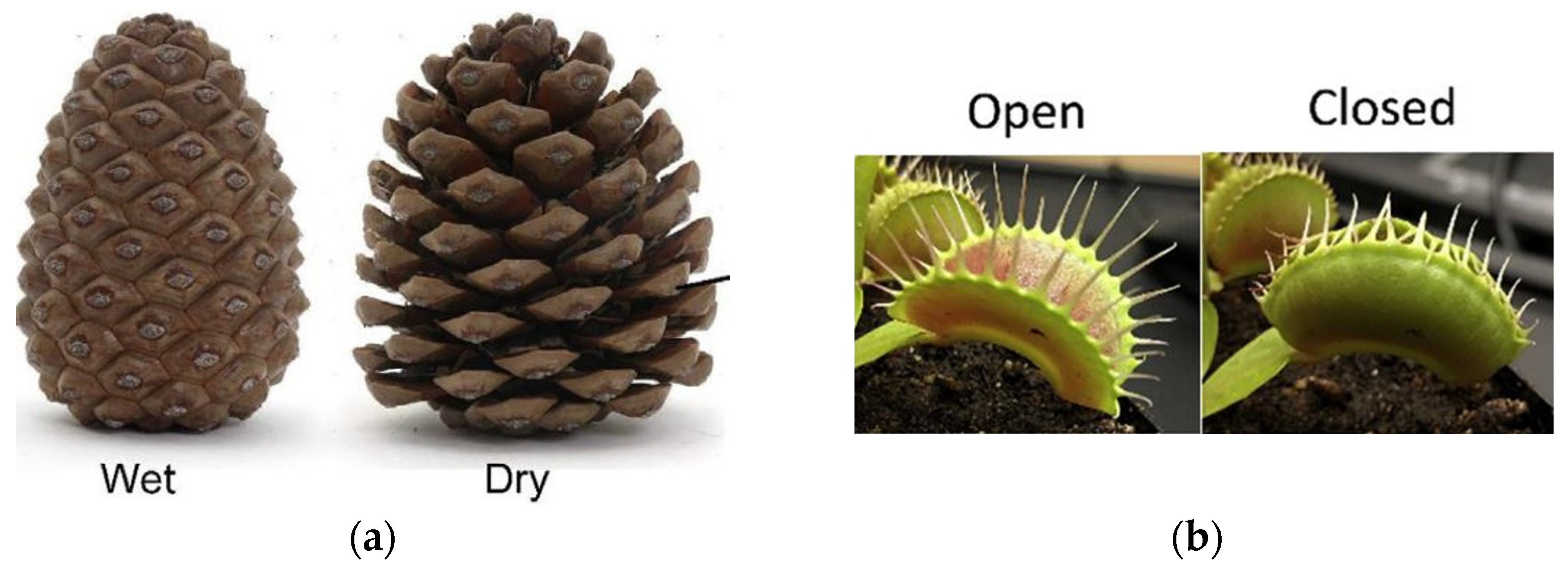
Figure 1. (a) Pinecone in a wet and a dry environment (source: reproduced with permission from Elsevier [5]); (b) flytrap plant eating an insect (source: reproduced with permission from Elsevier [6]).
Applsci 15 11641 g001
Figure 2. Overall concept of 4D printing.
Applsci 15 11641 g002
Figure 3. (A) Morphing structure prototype made of PLA and ABS. (BD) Response of the bi-polymer beam at different time frames during the actuation stage of the bilayer effect (source: reproduced with permission from Elsevier [21]).
Applsci 15 11641 g003
Figure 4. Antenna reflector of 5 m diameter (source: reproduced with permission from Elsevier [27]).
Applsci 15 11641 g004
Figure 6. Additive manufacturing methods classified according to the type of base material [41] (source: Creative Commons Attribution (CC BY) licence).
Applsci 15 11641 g006
Figure 7. Ultimaker Cura snapshots of different (a) infill patterns, (b) infill densities and (c) raster angles. The snapshots are taken from above the geometry, deposited on the printing bed. (d) Illustration of the printing speed and layer height (source: reproduced with permission from Springer Nature [42]).
Applsci 15 11641 g007
Figure 8. Scheme of the molecular mechanism of a thermally induced SMP with T t r a n s = T g . (i) The SMP is heated above T t r a n s , (ii) deformed to its temporary shape, (iii) and cooled down to fix its new shape. (iv) The SMP is heated again above T t r a n s to trigger the shape memory effect and comes back to its initial shape (source: reproduced with permission from Springer Nature [16]).
Applsci 15 11641 g008
Figure 9. Three-dimensional representation of a shape memory cycle for a thermosensitive SMP (source: reproduced with permission from Springer Nature [44]).
Applsci 15 11641 g009
Figure 10. (a) (i) FFF printing of a thermosensitive SMP. (ii) Sample after printing when cooled down under the glass transition temperature. (iii) Sample after release of the pre-strain once heated above the glass transition temperature [47] (source: Creative Commons Attribution 3.0 unported licence). (b) Bio inspiration of a robotic tendril with a programming step based on the pre-strain induced during FFF printing (source: Reprinted (adapted) with permission from [38]. Copyright 2025 American Chemical Society).
Applsci 15 11641 g010
Figure 11. DSC thermogram of a PLA sample and determination of the characteristic temperatures (red cross) (adapted from [73], source: reproduced with permission from Elsevier).
Applsci 15 11641 g011
Figure 12. Schematic stress–strain curve and definition of mechanical properties.
Applsci 15 11641 g012
Figure 13. Scheme of the (a) global coordinate system of a laminate and (b) the local coordinate system of layer within a laminate.
Applsci 15 11641 g013
Figure 14. Fracture surfaces observed by SEM of (a) ±45°, (b) 0° and (c) 90° 3D-printed CB/PLA samples [100]. (Source: Creative Commons Attribution (CC BY) licence).
Applsci 15 11641 g014
Figure 15. Definition of the angles for the calculation of the recovery ratio (adapted from [14] and reproduced with permission from John Wiley and Sons).
Applsci 15 11641 g015
Figure 16. Stiffness of 3D-printed by FFF CB/PLA samples depending on the nozzle diameter, layer height and raster angle [76] (source: CC BY 4.0 licence).
Applsci 15 11641 g016
Figure 17. Stress–strain curves of 3D-printed by FFF ABS samples with different nozzle diameters and layer heights, R being the ratio between the layer height and the nozzle diameter [106] (source: CC BY-NC-ND 4.0 licence).
Applsci 15 11641 g017
Figure 18. Evolution of the recovery ratio and recovery rate of PLA filled with thermochromic pigments depending on the (a) nozzle temperature, (b) thickness of the sample or (c) layer height [14] (source: reproduced with permission from John Wiley and Sons).
Applsci 15 11641 g018
Figure 19. Tensile test performed at a range of temperatures from 25 °C to 130 °C on (a) 90°, (b) ±45° and (c) 0° CB/PLA samples [78] (source: reproduced with permission from Elsevier).
Applsci 15 11641 g019
Figure 20. (a) Evolution of the resistivity of a filament of CB/PLA before and after extrusion during tensile testing [79] (source: CC BY 4.0 licence). (b) Stress–strain curves of 0° samples after Joule heating at different voltages [78] (source: reproduced with permission from Elsevier). (c) Evolution of the resistance of a 0° sample subjected to a tensile test. (0) The sample is in its initial state. (1) The tensile test stretches the sample according to the green arrows, increasing the electrical resistance. (2) The longitudinal strain keeps on growing while the transverse strain brings the CB aggregates together, therefore improving the electrical resistance. (3) The increasing stress applied leads to conductive pathways severed, resulting in an increase of the electrical resistance again, up to the failure of the specimen [74] (source: CC BY 4.0 licence).
Applsci 15 11641 g020
Figure 21. (a) Evolution of the recovery ratio and deployment time for PLA, PETG and mixed PLA and PETG devices (source: reproduced with permission from Springer Nature [104]). (b) Evolution of the deflection and temperature of a Joule device heated 500 times [30] (source: CC BY 4.0 licence).
Applsci 15 11641 g021
Figure 22. Experiments and simulation of carbon black PLA/TPU actuator ongoing a bending cycle and final recovery. (a) 150 s (shape memory effect triggered), (b) 200 s (maximum bending) and (c) 900 s (recovery).
Applsci 15 11641 g022
Table 1. Types of conductive SMPs and the triggering method used (MWCNT: Multi-walled carbon nanotubes; PLA: polylactic acid; CB: carbon black; X: not found in the article).
Triggering MethodFillerMatrixLab-Synthesised (LS)/Commercially Available (C)Ref
Magnetic fieldMWCNT coated with Fe3O4 nanoparticlesPoly (ε-caprolactone)LS[52]
Iron(III)oxide with core in silicaPolyetherurethane with a copolymerLS[56]
Fe3O4 nanoparticlesOligo (ε-caprolactone) dimethacrylate/butylacrylateLS[9]
Joule heatingSilver nanowiresPLALS[57]
NickelXX[13]
Gold nanoparticlesXX[13]
GraphenePLALS[58]
UV-cured epoxyLS[59]
MWCNTHydroxyethylmethacrylateLS[60]
PLA + thermoplastic polyurethaneLS[11]
PhenolicLS[61]
CNTPLAC[62]
PLALS[37]
PolyimideLS[63]
CBResinLS[64]
PhenolicLS[61]
PLAC[65]
Continuous carbon fibresEpoxyLS[66]
PolyamideC[67]
PLALS[68]
Table 2. Key performance metrics of FFF thermosensitive Shape Memory Polymers (PETG: polyethylene terephthalate glycol; TPU: thermoplastic polyurethane; CF: carbon fibres; CNT: carbon nanotubes; CB: carbon black).
MatrixFillerProperties
Conductivity Recovery Ratio (%)Recovery Time (s)Ref
PLAøø1003[104]
PETG1005
PLA-25/PETG-759028
PLA-50/PETG-509538
PLA-75/PETG-2510056
PLA printed at ±45°øø90140[37]
PLA printed at ±45°CNT81.3140
PLA/TPUCNT + CFø9425[11]
PLA/TPUCNT9675
PLAThermochromic pigmentsø926[14]
PLA printed at 0°8%wt CNT35 S/m83.380[105]
PLA printed at 45°9870
PLA printed at 90°9590
PLA + TPU21.5%wt CB3 S/m87.9900[17]
Table 3. Resistivity of CB/PLA depending on the raster angle [100] (source: Creative Commons Attribution (CC BY) licence).
Pattern and Orientation (°)Resistivity (Ω·mm)
90228 ± 6
0119 ± 2
±45155 ± 2
[06/±455/905]S134 ± 12
Disclaimer/Publisher’s Note: The statements, opinions and data contained in all publications are solely those of the individual author(s) and contributor(s) and not of MDPI and/or the editor(s). MDPI and/or the editor(s) disclaim responsibility for any injury to people or property resulting from any ideas, methods, instructions or products referred to in the content.