Article

Integration of Active Personal Dosimeters, Videos from In-Room Monitors, and Videos from the Surgeon’s Main Panel Reveal Pitfalls in Radiation Protection

1
Department of Radiological Technology, Kawasaki Medical School Hospital, Kurashiki 701-0192, Japan
2
Department of Occupational Hygiene, School of Health Sciences, University of Occupational and Environmental Health, Kitakyushu 807-8555, Japan
3
Department of Radiation Regulatory Science Research, Institute for Radiological Science, National Institutes for Quantum Science and Technology (QST), Chiba 263-8555, Japan
4
Department of Stroke Medicine and Endovascular Therapy, University of Occupational and Environmental Health, Kitakyushu 807-8555, Japan
5
Department of Radiology, Wakamatsu Hospital of the University of Occupational and Environmental Health, Kitakyushu 808-0024, Japan
6
Department of Occupational and Community Health Nursing, School of Health Sciences, University of Occupational and Environmental Health, Kitakyushu 807-8555, Japan
7
Department of Environmental Health, National Institute of Public Health, Wako 351-0197, Japan
*
Author to whom correspondence should be addressed.
Appl. Sci. 2025, 15(21), 11584; https://doi.org/10.3390/app152111584
Submission received: 27 September 2025 / Revised: 24 October 2025 / Accepted: 27 October 2025 / Published: 29 October 2025
(This article belongs to the Special Issue Latest Research in Radiation Detection and Protection)

Abstract

We examined whether synchronizing and analyzing three data sources, active personal dosimeter (APD) information, in-room monitoring camera footage, and the operator’s main angiography panel video, could identify opportunities to reduce occupational radiation exposure during cerebral angiography without therapeutic intervention. We analyzed the behavior of eight physicians and radiation doses measured outside the lead apron during 12 diagnostic cerebral angiography procedures performed between January and April 2024. Appropriate use of a ceiling-suspended radiation protective shield (CSRPS) was associated with approximately 70% exposure reduction. In addition, exposure during femoral arteriography (catheter advancement from femoral artery puncture to the aortic arch) accounted for approximately 50% of the total exposure, identifying both as effective intervention points. This approach identified operators’ incorrect use of radiation protection equipment and enabled clear feedback to operators on areas for improvements in radiation protection practices.

1. Introduction

The lens of the eye is one of most sensitive tissues to radiation, and there are concerns about the effects of radiation exposure on the lens in medical radiation workers. In 2011, the International Commission on Radiological Protection (ICRP) significantly lowered the threshold dose for cataracts, which had been set at 5 Gy for acute exposure and 8 Gy for fractionated and chronic exposure. Based on epidemiological evidence suggesting that the threshold dose for cataracts causing visual impairment may be lower than previously thought, the ICRP lowered the threshold to 0.5 Gy for all exposure scenarios (acute, fractionated, and chronic). Furthermore, the ICRP has recommended a substantial reduction in the equivalent dose limit to the lens of the eye for radiation workers, lowering it from the previous annual limit of 150 mSv to 100 mSv over 5 years (20 mSv per year on average), with no single year exceeding 50 mSv [1,2]. In Japan, the revised Ordinance on Prevention of Ionizing Radiation Hazards [3] enacted on 1 April 2021 includes these ICRP recommendations.
Since then, awareness of radiation protection among medical staff in Japanese clinical practice has increased. Numerous studies have reported on the use of radiation protective devices, such as the ceiling-suspended radiation protective shield (CSRPS) and couch-mounted radiation protective curtain (CMRPC) [4,5,6,7,8,9,10], and personal protective equipment (lead aprons, lead thyroid protectors, lead glasses, and so on) [6,8,10,11,12,13,14,15,16], with investigations into lens dose [4,6,7,10,11,12,15,16,17,18,19,20,21,22,23]. However, in actual clinical settings, it is not always easy to objectively assess whether these devices are being used correctly.
Our previous studies reported that the lens equivalent dose for physicians involved in Interventional Radiology may exceed the annual 20 mSv dose limit without appropriate shielding [24,25]. Physicians are educated that, to reduce their radiation exposure, they must first minimize irradiation, to reduce scattered radiation generation. They must then use radiation protective devices such as CSRPS and CMRPC appropriately to shield themselves from scattered radiation as much as possible. When exposure cannot be sufficiently controlled, they must wear personal protective equipment such as lead aprons, lead thyroid protectors, and lead glasses. However, concrete verification methods have not been established to clarify how operators are exposed to unnecessary radiation or whether radiation protective devices are effective.
Commercially available active personal dosimeters (APDs; active personal dosimeters) enable real-time operator dose measurement, and their use can reduce unnecessary exposure [4,26,27,28,29,30,31]. Nevertheless, when real-time high-dose exposure is detected without identifying the concurrent task, it is difficult to provide concrete feedback on high-risk behaviors. Kato et al. [4] evaluated the causes of increased operator radiation exposure during percutaneous coronary intervention (PCI) by analyzing data from an APD attached to the operator’s left temple, combined with video footage from an intraoperative monitoring camera positioned caudally to the patient. The average lens radiation dose per procedure for the operator was 115.7 µSv. CSRPS is a protective device that efficiently blocks scattered radiation originating from the patient’s body and imaging couch, which is a scatterer, from entering the operator’s upper body, including the lens of the eye. However, image analysis from the in-room monitoring camera revealed that the radiation dose rate for operators working inside the angiography room without retreating to the control room varied significantly depending on CSRPS usage, ranging from 1.16 to 3.17 mSv/h. Furthermore, scenes where the CSRPS was not used appropriately during imaging exposure averaged 78.4% per procedure. This inappropriate use of CSRPS was reported to be driving up the operator lens dose [4].
Because radiation cannot be seen or felt, it is essential to objectively verify the circumstances of exposure and whether radiation protection or personal protective equipment is being used effectively. Therefore, in this study, we attempted to analyze synchronized video footage from dual-angle in-room monitoring cameras positioned at the patient’s caudal and right sides within the operating room—our unique approach to obtain more detailed information on the use of radiation protective devices—alongside exposure dose data from APDs attached to the physician’s left neck and left anterior chest. We also analyzed recorded video from the operator’s main angiography monitor. This novel approach aimed to verify whether it is possible to identify radiation protection issues requiring better operator practices in the previously unreported field of cerebral angiography.

2. Materials and Methods

2.1. Study Population

Twelve cerebral angiographies performed between January and April 2024 at a university hospital in Japan were analyzed. The procedures were conducted by eight physicians employed at the hospital (three specialists and five residents with ≤6 years of post-license experience). Cerebral angiography includes angiography with therapeutic intervention and angiography without therapeutic intervention. In the former case, endovascular treatment, the target disease, and the complexity of the procedure significantly influence radiation exposure doses for both the patient and operator. In contrast, cerebral angiography without therapeutic intervention involves standardized procedures. Since factors contributing to radiation exposure can be standardized, except for the use of radiation protective devices, this study focused on cerebral angiography without therapeutic intervention.

2.2. Angiography System

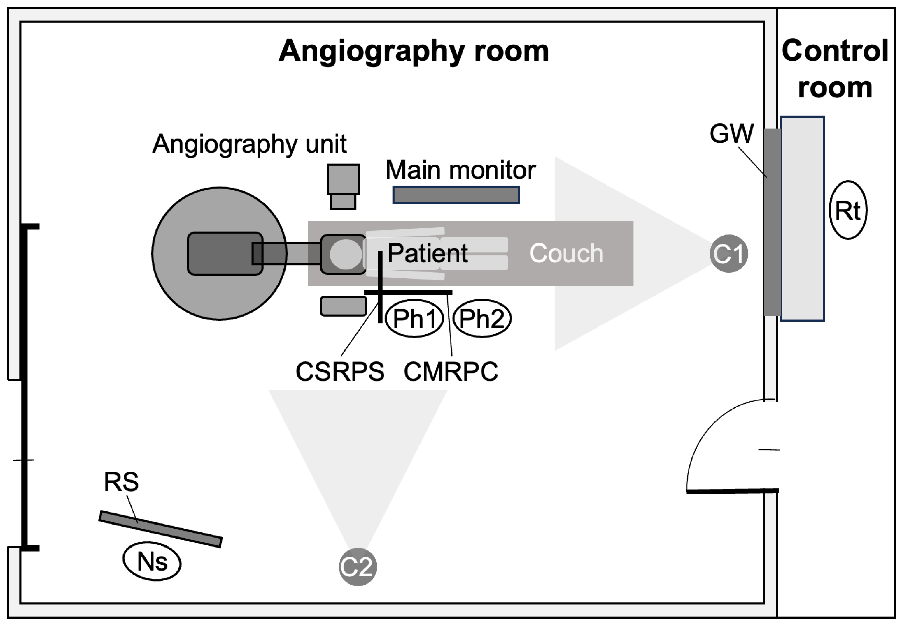
Angiography was performed using a biplane angiography system (Alphenix INFX-8000V, Canon Medical Systems Co., Ltd., Ohtawara, Japan) equipped with a CSRPS (KYOWAGLAS-XA, 0.5-mm Pb equivalent, KURARAY Trading Co., Ltd., Osaka, Japan) and a CMRPC (KYOWSGLAS-SA-35, 0.35-mm Pb equivalent, KURARAY Trading Co., Ltd., Osaka, Japan) (Figure 1).

2.3. Active Personal Dosimeter System

We used the RaySafe i3 (Unfors RaySafe AB, Billdal, Sweden) active dose-monitoring system, which measures scattered radiation (1-cm dose equivalent) in real time, displaying dose rate and cumulative dose. Response time is <1 s at >100 µSv/h and <5 s at <100 µSv/h; the integration interval is 1 s and the detection limit is <30 µSv/h. For each case, two operators wore one APD each, placed outside personal protective equipment at the left cervical region and left anterior chest (Figure 2).

2.4. Placement of Staff and In-Room Monitoring Cameras

In cerebral angiography without therapeutic intervention, the team comprises two operators, a circulating nurse, and a radiologic technologist (Figure 3). Two in-room monitoring cameras simultaneously filmed movements from the patient’s caudal side and right sides. When an automatic contrast injector was used, both operators typically moved to the control room to avoid exposure, whereas when manual contrast injection was performed, the operators remained in the angiography suite during the procedure.

2.5. Recording of the Operator’s Main Monitor Screen

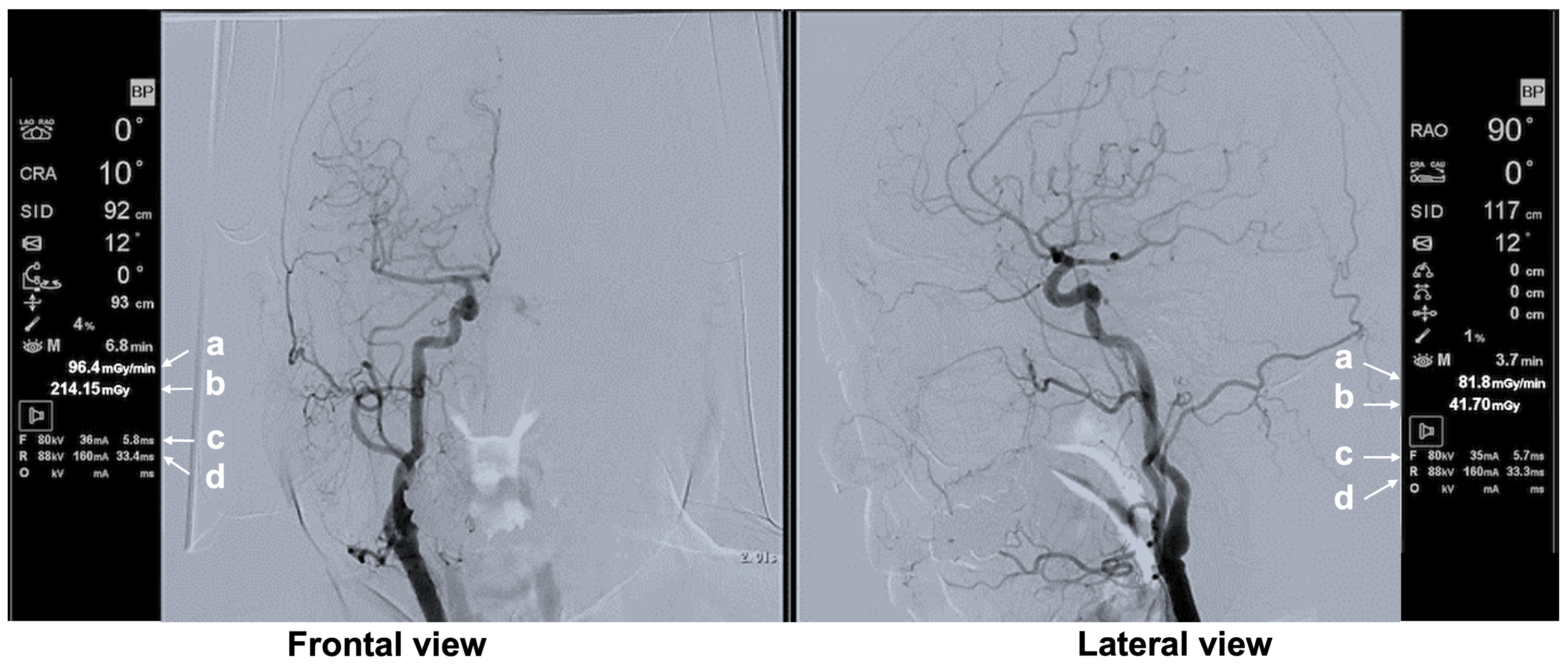
The image signal sent to the operator’s main angiography monitor was branched to a recorder, allowing video capture of the entire main monitor screen during the procedure. In addition to fluoroscopic and radiographic images, the main monitor displayed exposure-related parameters in real time, including the air kerma at the patient entrance reference point (Ka,r), tube voltage, tube current, pulse width, source-to-image receptor distance, and exposure angle (Figure 4).

2.6. Analysis of Operator Unprotected Dose

Because the primary operator (first position) and assistant (second position) frequently switched roles, in-room camera footage was used to identify operator position, and unprotected dose was calculated separately for each position (Figure 3).
Then, the unprotected dose was computed from APD unprotected dose rate values (measured outside the lead apron and lead thyroid protector) integrated every second by the RaySafe i3, using Equation (1):
U n p r o t e c t e d   d o s e   ( m S v )   =   Σ   [ U n p r o t e c t e d   d o s e   r a t e   ( m S v / h )   ×   E x p o s u r e   t i m e   ( h ) ]
where the unprotected dose rate (mSv/h) is refreshed every second by the RaySafe i3 system, and the exposure time (h) is the duration during which that dose rate persists. This data was exported from the RaySafe i3 system in CSV format after the angiography procedure was completed.

2.7. Analysis of Factors Affecting Operator Unprotected Dose Rate

We analyzed 62,704 data points on operator unprotected dose rate from the 12 procedures. Because the RaySafe i3 response time extends to 5 s at low dose rates (<0.1 mSv/h), we ensured 1-s sampling (necessary for video alignment) while considering analyst workload. Therefore, we extracted 266 scenes (2619 data points) in which either cervical or chest unprotected dose rate was ≥1 mSv/h during fluoroscopy or radiography. We limited the analysis to scenes in which the operator was in the first position and categorized them as before and after CSRPS use. Ultimately, 52 scenes (1641 data points) of before CSRPS use (catheter advancement to the aortic arch) and 47 scenes (532 data points) of after CSRPS use were extracted. For each scene, CSRPS/CMRPC use and operator position were determined from in-room videos, and exposure-related parameters from the main monitor were incorporated. As an indicator of appropriate CSRPS use, the cervical/chest unprotected dose rate ratio was calculated using the following Equation (2):
C e r v i c a l / C h e s t U n p r o t e c t e d   D o s e   R a t e   R a t i o =   C e r v i c a l   U n p r o t e c t e d   D o s e   R a t e   ( m S v / h )   /   C h e s t   U n p r o t e c t e d   D o s e   R a t e   ( m S v / h )

2.8. Statistical Analysis

Statistical analyses were performed using EZR version 1.55 [32]. Differences in unprotected dose rate by operator position and CSRPS use were tested with the Mann–Whitney U test (two-tailed). Differences with p < 0.05 were considered significant.

3. Results

3.1. Operator Unprotected Dose Rate and Unprotected Dose

Across the 12 procedures, the median unprotected dose before CSRPS introduction—from femoral artery puncture to catheter advancement into the aortic arch—was 23.89 µSv at the cervical region and 45.60 µSv at the chest. These values were nearly half of the medians for the entire procedure (49.23 µSv cervical region and 95.49 µSv chest) (Table 1). The two operators frequently switched positions and spent varying amounts of time in each position. Consequently, even within the same case, a significant difference in unprotected dose was observed between the two operators (Table 1). Although there was no significant difference in unprotected dose between the chest and cervical region before CSRPS introduction (median 45.60 µSv and 23.89 µSv, respectively; p = 0.053), the unprotected dose at the chest was significantly higher than that at the cervical region for the entire procedure (median 95.49 µSv and 49.23 µSv, respectively; p < 0.01) (Table 1). By operator position, unprotected dose at the cervical and chest regions was significantly higher in the first position than in the second position (p < 0.01) (Table 2).
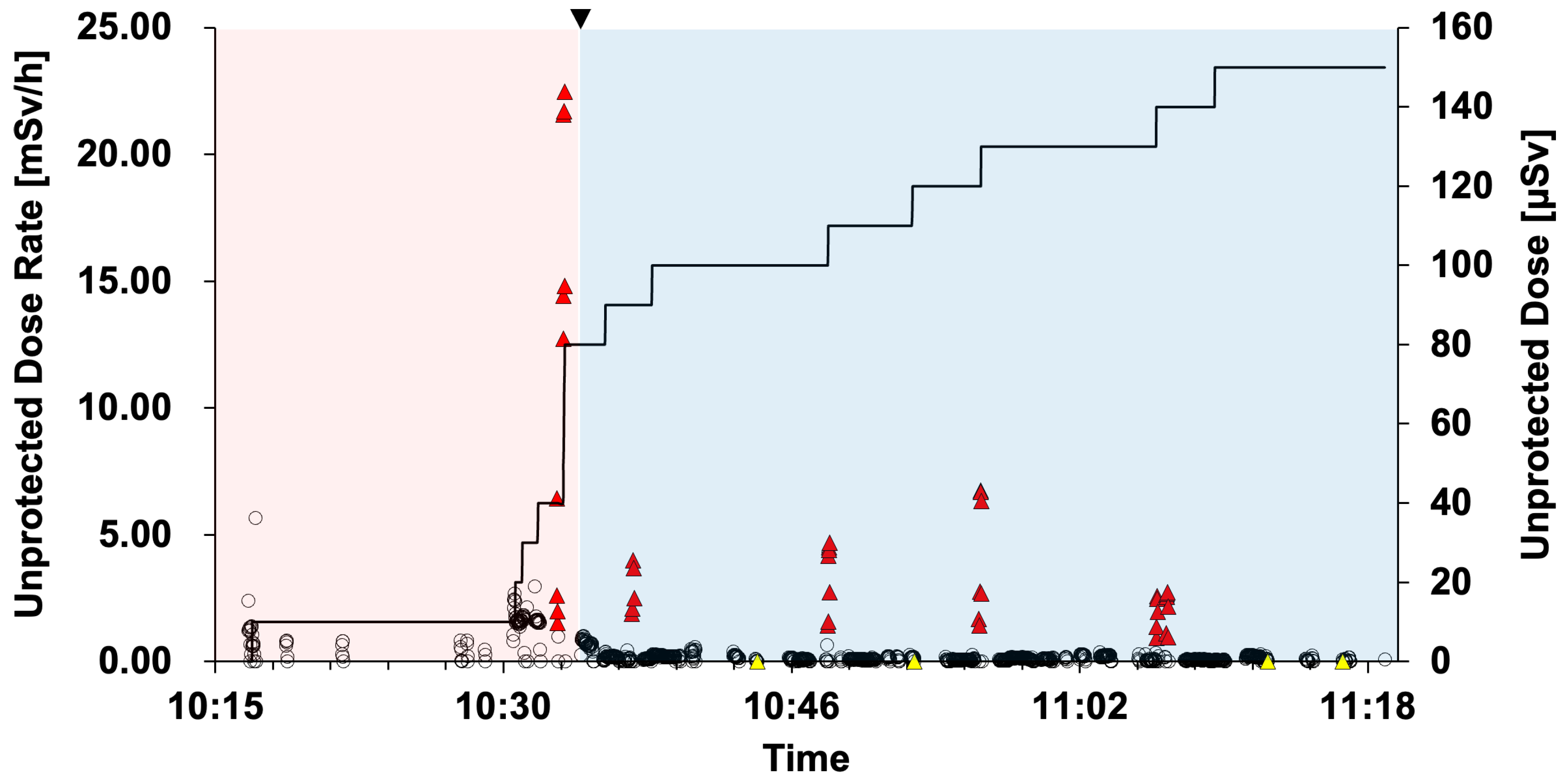
Figure 5 illustrates a cervical unprotected dose rate and unprotected dose analysis obtained with the RaySafe i3 (Case 2, Resident F; Table 1). From right femoral puncture until catheter advancement to the aortic arch, CSRPS could not be introduced because the operator stood close to the fluoroscopic field. This interval was mostly centered on fluoroscopy; thus, the unprotected dose rate from scatter radiation remained relatively low. However, because Resident F performed femoral arteriography (digital subtraction angiography [DSA] of the femoral artery) with manual contrast injection without retreating to the control room, the unprotected dose rate increased marked, substantially raising the unprotected dose.

3.2. Effect of CSRPS Placement on Operator Unprotected Dose Rate

Unprotected dose rates and cervical/chest ratios for the 47 scenes (532 data points) after CSRPS introduction are shown in Supplementary Table S1. These scenes did not involve fluoroscopy; all were DSA, which yields higher unprotected dose rates. After excluding four scenes (57 data points) that involved inappropriate CMRPC use, 43 scenes (475 data points) remained. Cervical unprotected dose rate was significantly lower with appropriate CSRPS use (p < 0.01), with a median reduction of 70% (1 − 0.65/2.20 = 0.70). In contrast, chest unprotected dose rate did not differ significantly (p = 0.917) (Table 3).
The cervical/chest unprotected dose rate ratio was 0.32 ± 0.05 (mean ± SD) with appropriate CSRPS use and 1.25 ± 0.76 (mean ± SD) with inappropriate CSRPS use (p < 0.01) (Figure 6).

3.3. Presentation of Typical Scenes

3.3.1. Typical Scene 1 (Case 5)

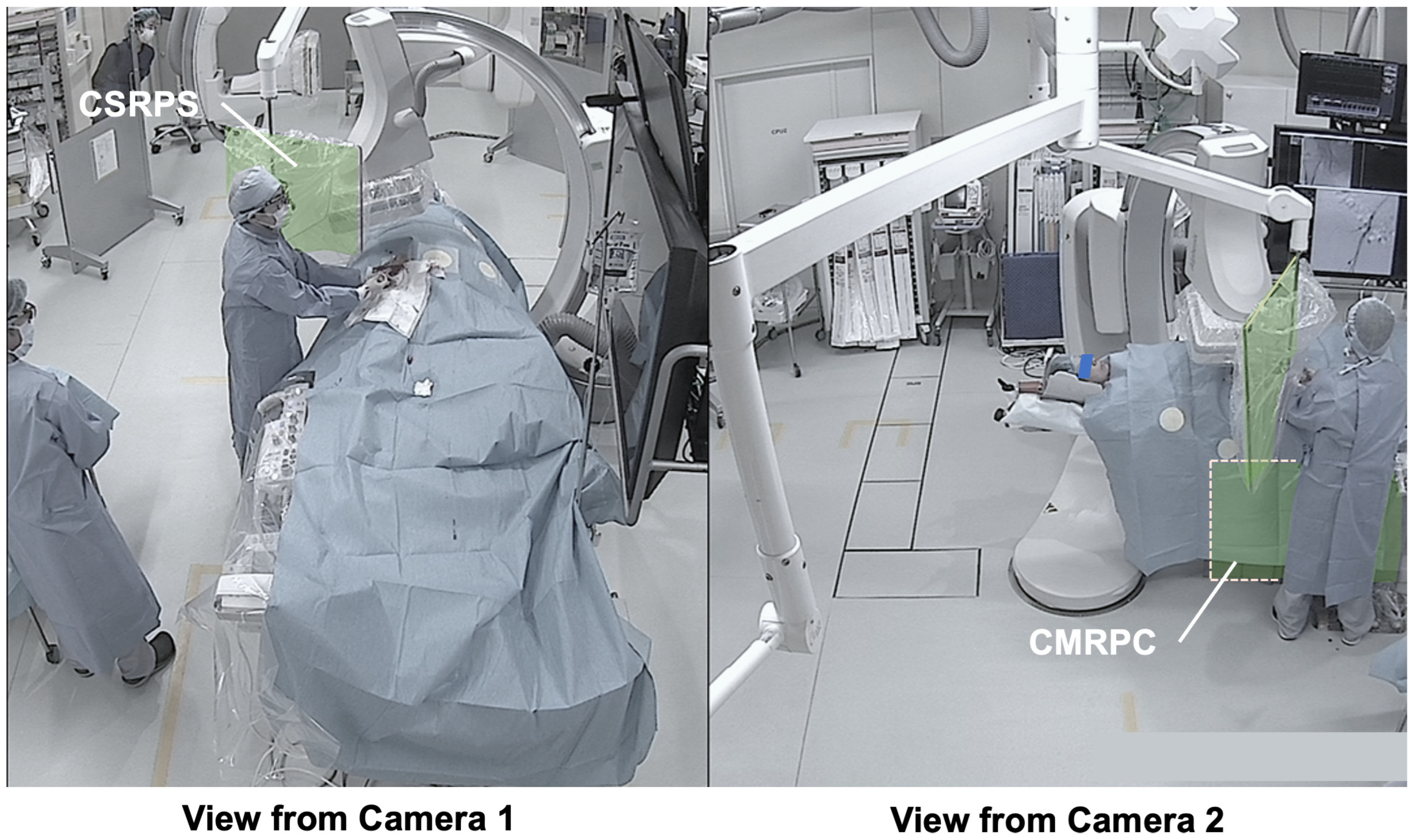
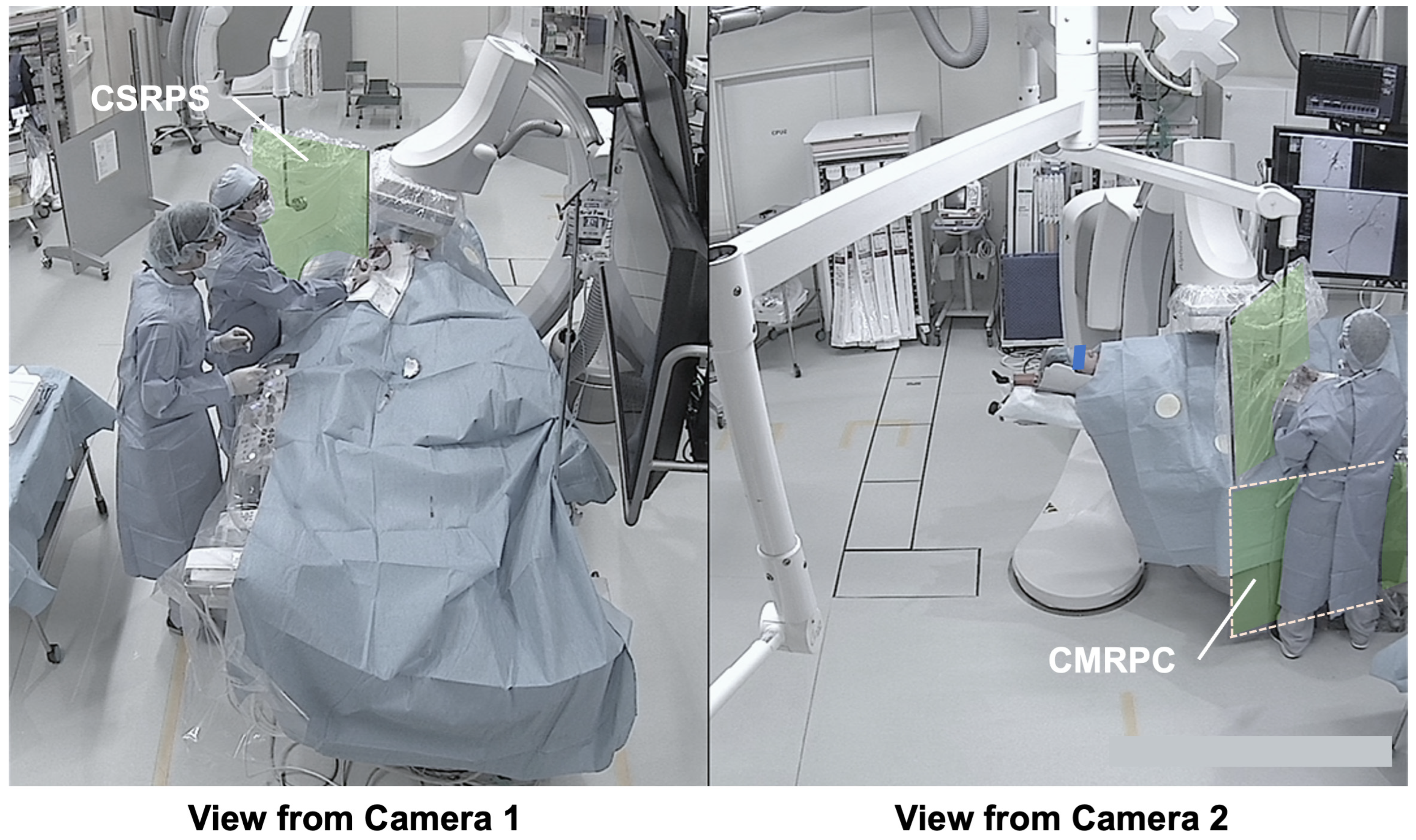
The patent’s right femoral artery was punctured and a catheter was inserted. To confirm the access route, femoral arteriography (DSA) was performed in the right anterior oblique projection. The operator remained in the angiography suite and manually injected a contrast agent (Figure 7). Because the CSRPS was not properly deployed due to space limitations and the operator was standing close to the fluoroscopic field, the unprotected dose rate was high (Table 4).

3.3.2. Typical Scene 2 (Case 5)

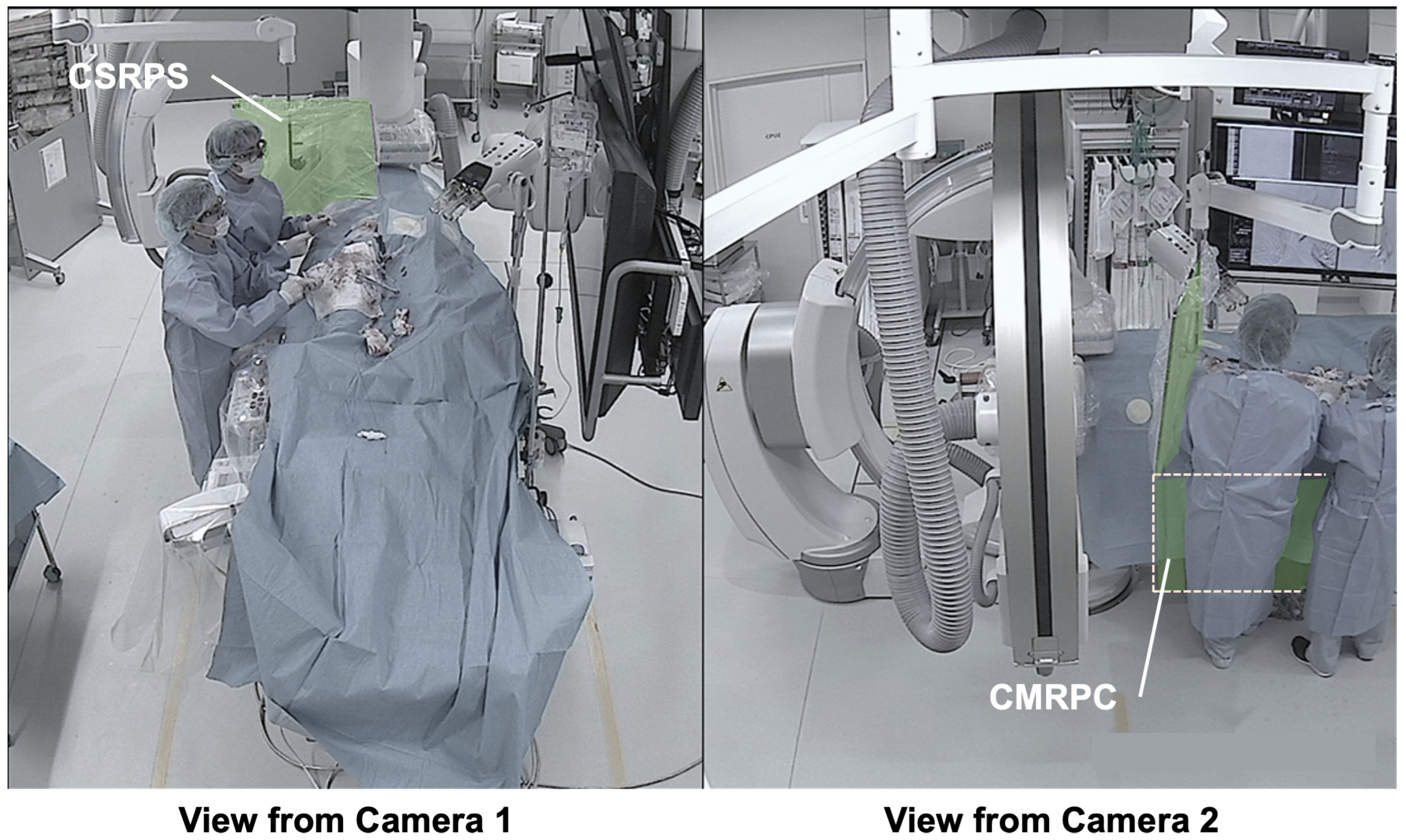
Same case as Scene 1. Femoral arteriography (DSA) was performed in the left anterior oblique projection (Figure 8). Compared with the right anterior oblique position in Scene 1, the unprotected dose rate was higher (Table 4).

3.3.3. Typical Scene 3 (Case 3)

CSRPS and CMRPC were used appropriately, and the operator stood close to the CSRPS (Figure 9). The unprotected dose rate was low at both the cervical and chest regions (Table 4).

3.3.4. Typical Scene 4 (Case 3)

Same case as Scene 3. Although both CSRPS and CMRPC were used, a gap remained between the CSRPS lower edge and the patient’s trunk, and the CSRPS–operator distance was greater (Figure 10). Although the angiography parameters of this scene were similar to those of Scene 3, the unprotected dose rates at both regions were approximately double those of Scene 3 (Table 4).

3.3.5. Typical Scene 5 (Case 4)

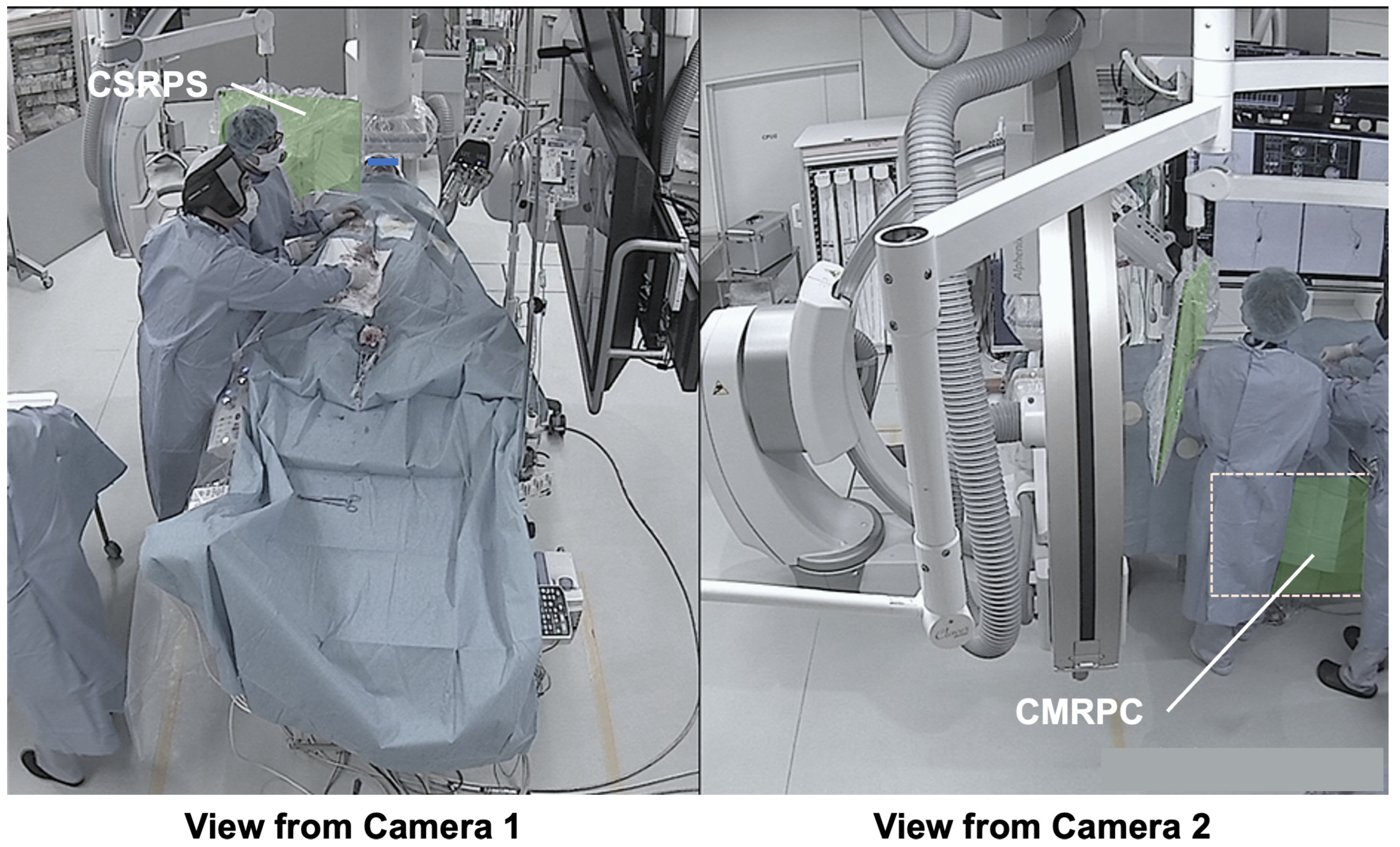
Although Ka,r was lower in this scene than in Scene 4, a gap remained between the CSRPS lower edge and the patient’s trunk, and the CMRPC did not adequately cover the first-position operator’s lower body (Figure 11). Consequently, the unprotected dose rate—particularly at the chest—was high (Table 4).

4. Discussion

Prior reports on APD-guided exposure management have suggested that APDs can induce behavioral change, optimize protective device use, and reduce exposure, via a real-time dose display instigating immediate behavior correction and heightened operator awareness [28,30,31]. Conversely, Miller et al. found that APDs alone did not significantly reduce scatter dose, possibly because operators focused on the main angiography monitor and overlooked a separate dose display [33]. By synchronizing APD data, in-room video, and main monitor information, we identified previously unrecognized inappropriate use of radiation protective devices and explained corrective strategies. Specifically, compared to the report by Kato et al. on attempts to synchronize APD data with unidirectional in-room video [4],
  • Dual-angle in-room monitoring cameras provided good depth perception, making it easier to assess the appropriateness of CSRPS placement;
  • The added camera on the patient’s right side allowed confirmation of the distance between the CSRPS and the operator;
  • The additional camera on the patient’s right side allowed confirmation of the CMRPC placement status under the patient bed;
  • Time-synchronized main monitor information enabled verification of the specific operator actions and irradiation conditions during exposure.
These provide practical feedback to operators; however, whether post-procedure (rather than real-time) feedback effectively reduces exposure warrants further study.
In this cohort, cervical unprotected dose averaged 58.48 ± 39.39 µSv per case (mean ± SD) (Table 1). If one physician performed approximately 150 diagnostic procedures annually, the dose from diagnostic work alone would likely exceed 6 mSv. Adding approximately 50 therapeutic cerebral angiography procedures would leave only a little margin before the lens equivalent-dose limit (20 mSv/year) is exceeded, underscoring the need for active interventions to mitigate occupational radiation exposure. Correcting inappropriate CSRPS use reduced median cervical unprotected dose rate from 2.20 to 0.65 mSv/h (70% reduction) (Table 4), indicating that promoting proper CSRPS use can lower operator lens dose. Unexpectedly, exposure during the pre-target phase (femoral arteriography and imaging before the catheter reached the common carotid or vertebral artery) accounted for approximately 50% of the total cervical unprotected dose (Table 1). Because these steps are not the main diagnostic objective, image-quality demands are less stringent, leaving substantial room for dose reduction; identifying this period as an intervention point is a major contribution of this study.
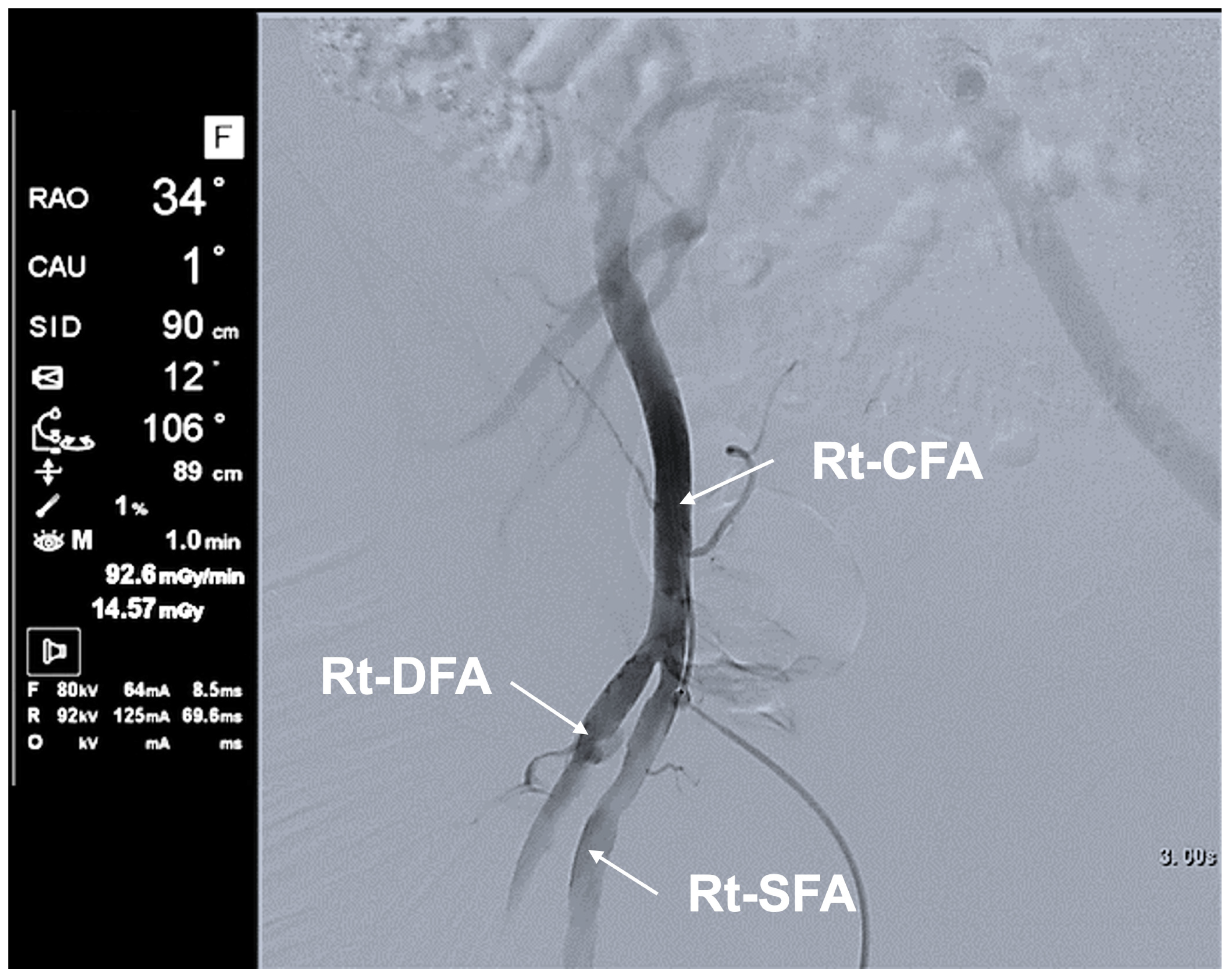
At the hospital where this study was conducted, after femoral puncture, operators commonly perform femoral arteriography by manually injecting contrast through the sheath side port to confirm guidewire course, detect perforation/dissection, and assess branches for hemostatic device use (Figure 12). Close operator-to-field proximity limits space for proper CSRPS deployment, increasing cervical unprotected dose. Lateral C-arm tilt to separate overlapping branches increases the depth along the beam path, inducing auto-exposure control and raising output and scatter—especially in left anterior oblique (Figure 8), where the tube approaches the operator’s lower body. In this situation, the operator is heavily affected by scatter more than in right anterior oblique (Figure 7), elevating the unprotected cervical dose rate (Table 4). Castle et al. reported that femoral arteriography can reduce femoral complications by approximately 40% [34] and is essential, minimizing DSA in favor of fluoroscopy storage. However, mindful beam direction is recommended [28,35]. Practically, CSRPS should be positioned as early as possible after puncture, and CMRPC placement should be completed before draping to ensure full lower-body coverage.
Consistent with phantom data by Jia et al. [36], the clinical data in the present study showed lower cervical unprotected doses for second-position versus first-position operators (19.59 ± 12.86 µSv vs. 48.19 ± 35.03 µSv; Table 2). Working from the second position, farther from the tube, is protective but not always feasible. Therefore, lead glasses and correct CSRPS/CMRPC use remain essential.
The study identified four practical points for device use in cerebral angiography without therapeutic intervention (Table 5).
While APD-plus-video can verify adherence, it is labor-intensive. As a simpler indicator, the cervical/chest unprotected dose rate ratio averaged 0.32 ± 0.05 (n = 4, mean ± SD) with appropriate CSRPS use versus 1.25 ± 0.76 (n = 39, mean ± SD) with inappropriate use (Supplementary Table S1, Table 4, Figure 6), suggesting its potential utility as a practical indicator. However, larger studies are needed to validate this metric.
The study had some limitations. First, we estimated that correct CSRPS use can reduce cervical unprotected dose by approximately 70%; however, by restricting the analysis to higher dose rates (≥1 mSv/h), we observed that even “appropriate” scenes (n = 4, Supplementary Table S1) may have bordered on suboptimal use. Second, the small sample could have underestimated the effect size.

5. Conclusions

Synchronizing APD data, in-room video, and exposure-related parameters from the operator’s main monitor identified previously unrecognized misuses of radiation protective devices and enabled clear corrective strategies. Femoral arteriography and imaging in the aortic-arch approach phase offer substantial opportunities for operator dose reduction and should be targeted for radiation protection interventions during cerebral angiography without therapeutic intervention. Appropriate use of CSRPS and CMRPC is a key intervention point for reducing occupational radiation exposure.

Supplementary Materials

The following supporting information can be downloaded at: https://www.mdpi.com/article/10.3390/app152111584/s1, Table S1. CSRPS and CMRPC placement status and operator unprotected dose-rate (47 extracted scenes, 532 data points).

Author Contributions

Conceptualization, T.I., G.H. and T.M.; methodology, G.H. and T.M.; validation, G.H. and T.M.; investigation, Y.T., T.K. (Toru Kurokawa) and K.N.; data curation, G.H., K.N., T.K. (Tomoko Kuriyama), K.M., S.M. and T.I.; writing—original draft preparation, G.H.; writing—review and editing, T.M.; visualization, G.H.; supervision, T.M. and T.I.; project administration, T.M.; funding acquisition, T.M. All authors have read and agreed to the published version of the manuscript.

Funding

This research was funded by the Japan Society for the Promotion of Science KAKENHI (to T.M.), grant number 24H00665; Ministry of Health, Labour and Welfare, the workers’ accident disease clinical study project, grant number 240401-02 (to T.M).

Institutional Review Board Statement

This study is a retrospective observational analysis of existing individual radiation exposure doses of healthcare workers. Since measuring individual doses is a statutory requirement, an ethical review was not necessary. However, because individual doses are private information, written consent was obtained from the participants after approval from the Ethics Committee for this paper. The study was conducted in accordance with the Declaration of Helsinki and was approved by the Ethics Committee of the University of Occupational and Environmental Health. Reference number: ID24-015, with the original version (1.0) approved by the IRB on 25 March 2025, and a revised version (2.0) approved on 12 August 2025.

Informed Consent Statement

Informed consent was obtained from all subjects involved in the study.

Data Availability Statement

The data presented in this study are available at the request of the corresponding author due to the study’s aims and ethics.

Acknowledgments

The authors would like to thank all physicians and medical staff who participated in this project.

Conflicts of Interest

The authors declare no conflicts of interest.

Abbreviations

The following abbreviations are used in this manuscript:
APDactive personal dosimeter
CSRPSceiling-suspended radiation protective shield
CMRPCcouch-mounted radiation protective curtain
C-CAGcommon carotid artery angiography
SAGsubclavian artery angiography
DSAdigital subtraction angiography
RAOright anterior oblique
LAOleft anterior oblique

References

  1. ICRP. Statement on Tissue Reactions; ICRP: Ottawa, ON, Canada, 2011; ref 4825-3093-1464. [Google Scholar]
  2. ICRP. ICRP Statement on Tissue Reactions/Early and Late Effects of Radiation in Normal Tissues and Organs—Threshold Doses for Tissue Reactions in a Radiation Protection Context. ICRP publication 118. Ann. ICRP 2012, 41, 1–322. [Google Scholar] [CrossRef]
  3. Ministry of Health, Labour and Welfare Ordinance Eighty-Second Number. Available online: https://www.mhlw.go.jp/content/001080975.pdf (accessed on 1 September 2025).
  4. Kato, T.; Fujisawa, M.; Hattori, K.; Yamada, A.; Haga, Y.; Kaga, Y.; Abe, M.; Inaba, Y.; Chida, K. Initial considerations for real-time measurement of lens dose in PCI surgeons. Nippon Hoshasen Anzen Kanri Gakkai-Shi 2023, 22, 10–18. [Google Scholar] [CrossRef]
  5. Matsuzaki, S.; Moritake, T.; Morota, K.; Nagamoto, K.; Nakagami, K.; Kuriyama, T.; Kunugita, N. Development and assessment of an educational application for the proper use of ceiling-suspended radiation shielding screens in angiography rooms using augmented reality technology. Eur. J. Radiol. 2021, 143, 109925. [Google Scholar] [CrossRef] [PubMed]
  6. Sakamoto, H.; Moritake, T.; Sun, L.; Kobayashi, I.; Kawauchi, S.; Abe, T.; Tsukamoto, A.; Morimoto, Y.; Daida, H.; Matsumaru, Y. Monitoring and protection against radiation dose to eyes of operators performing neuroendovascular procedures: A nationwide study in Japan. J. Neuroendovasc. Ther. 2022, 16, 354–360. [Google Scholar] [CrossRef]
  7. Sumi, S.; Yasuda, M.; Ohtani, H.; Ishimoto, Y.; Wakabayashi, K.; Sai, S.; Sato, H.; Kato, K. The effect of radiation protection education for the operators’ ocular lens in cardiac catheterization. Nihon Hoshasen Gijutsu Gakkai Zasshi 2021, 77, 710–717. [Google Scholar] [CrossRef] [PubMed]
  8. Chida, K. What are useful methods to reduce occupational radiation exposure among radiological medical workers, especially for interventional radiology personnel? Radiol. Phys. Technol. 2022, 15, 101–115. [Google Scholar] [CrossRef]
  9. Nakagami, K.; Moritake, T.; Nagamoto, K.; Morota, K.; Matsuzaki, S.; Kuriyama, T.; Kunugita, N. Strategy to reduce the collective equivalent dose for the lens of the physician’s eye using short radiation protection curtains to prevent cataracts. Diagnostics 2021, 11, 1415. [Google Scholar] [CrossRef]
  10. Akahane, M.; Yoshioka, N.; Kiryu, S. Radiation protection of the eye lens in fluoroscopy-guided interventional procedures. Interv. Radiol. 2022, 7, 44–48. [Google Scholar] [CrossRef]
  11. Haga, Y.; Chida, K.; Kaga, Y.; Sota, M.; Meguro, T.; Zuguchi, M. Occupational eye dose in interventional cardiology procedures. Sci. Rep. 2017, 7, 569. [Google Scholar] [CrossRef]
  12. Kato, M.; Chida, K.; Ishida, T.; Toyoshima, H.; Yoshida, Y.; Yoshioka, S.; Moroi, J.; Kinoshita, T. Occupational radiation exposure of the eye in neurovascular interventional physician. Radiat. Prot. Dosim. 2019, 185, 151–156. [Google Scholar] [CrossRef]
  13. Kato, M.; Chida, K.; Munehisa, M.; Sato, T.; Inaba, Y.; Suzuki, M.; Zuguchi, M. Non-lead protective aprons for the protection of interventional radiology physicians from radiation exposure in clinical settings: An initial study. Diagnostics 2021, 11, 1613. [Google Scholar] [CrossRef]
  14. Sato, T.; Eguchi, Y.; Yamazaki, C.; Hino, T.; Saida, T.; Chida, K. Development of a new radiation shield for the face and neck of IVR physicians. Bioengineering 2022, 9, 354. [Google Scholar] [CrossRef]
  15. Endo, M.; Haga, Y.; Sota, M.; Tanaka, A.; Otomo, K.; Murabayashi, Y.; Abe, M.; Kaga, Y.; Inaba, Y.; Suzuki, M.; et al. Evaluation of novel X-ray protective eyewear in reducing the eye dose to interventional radiology physicians. J. Radiat. Res. 2021, 62, 414–419. [Google Scholar] [CrossRef] [PubMed]
  16. Fujibuchi, T.; Fujita, K.; Igarashi, T.; Nishimaru, E.; Horita, S.; Sakurai, R.; Ono, K. Proposal for reduction measures of eye lens exposure based on actual exposure management in radiation-exposed medical staff. Nihon Hoshasen Gijutsu Gakkai Zasshi 2021, 77, 160–171. [Google Scholar] [CrossRef]
  17. Hamada, N.; Fujimichi, Y. Classification of radiation effects for dose limitation purposes: History, current situation and future prospects. J. Radiat. Res. 2014, 55, 629–640. [Google Scholar] [CrossRef] [PubMed]
  18. Hamada, N.; Fujimichi, Y.; Iwasaki, T.; Fujii, N.; Furuhashi, M.; Kubo, E.; Minamino, T.; Nomura, T.; Sato, H. Emerging issues in radiogenic cataracts and cardiovascular disease. J. Radiat. Res. 2014, 55, 831–846. [Google Scholar] [CrossRef] [PubMed]
  19. Ishii, H.; Chida, K.; Satsurai, K.; Haga, Y.; Kaga, Y.; Abe, M.; Inaba, Y.; Zuguchi, M. A phantom study to determine the optimal placement of eye dosemeters on interventional cardiology staff. Radiat. Prot. Dosim. 2019, 185, 409–413. [Google Scholar] [CrossRef]
  20. Ishii, H.; Chida, K.; Satsurai, K.; Haga, Y.; Kaga, Y.; Abe, M.; Inaba, Y.; Zuguchi, M. Occupational eye dose correlation with neck dose and patient-related quantities in interventional cardiology procedures. Radiol. Phys. Technol. 2022, 15, 54–62. [Google Scholar] [CrossRef]
  21. Kuriyama, T.; Moritake, T.; Nakagami, K.; Morota, K.; Hitomi, G.; Kitamura, H. Background factors affecting the radiation exposure of the lens of the eye among nurses in interventional radiology: A quantitative observational study. Nurs. Rep. 2024, 14, 413–427. [Google Scholar] [CrossRef]
  22. Ohno, S.; Konta, S.; Shindo, R.; Yamamoto, K.; Isobe, R.; Inaba, Y.; Suzuki, M.; Zuguchi, M.; Chida, K. Effect of backscatter radiation on the occupational eye-lens dose. J. Radiat. Res. 2024, 65, 450–458. [Google Scholar] [CrossRef]
  23. Yamada, A.; Haga, Y.; Sota, M.; Abe, M.; Kaga, Y.; Inaba, Y.; Suzuki, M.; Tada, N.; Zuguchi, M.; Chida, K. Eye lens radiation dose to nurses during cardiac interventional radiology: An initial study. Diagnostics 2023, 13, 3003. [Google Scholar] [CrossRef]
  24. Moritake, T.; Matsumaru, Y.; Takigawa, T.; Nishizawa, K.; Matsumura, A.; Tsuboi, K. Dose measurement on both patients and operators during neurointerventional procedures using photoluminescence glass dosimeters. AJNR Am. J. Neuroradiol. 2008, 29, 1910–1917. [Google Scholar] [CrossRef]
  25. Matsuzaki, S.; Moritake, T.; Sun, L.; Morota, K.; Nagamoto, K.; Nakagami, K.; Kuriyama, T.; Hitomi, G.; Kajiki, S.; Kunugita, N. The Effect of Pre-Operative Verbal Confirmation for Interventional Radiology Physicians on Their Use of Personal Dosimeters and Personal Protective Equipment. Int. J. Environ. Res. Public Health 2022, 19, 16825. [Google Scholar] [CrossRef]
  26. Hattori, K.; Inaba, Y.; Kato, T.; Fujisawa, M.; Yasuno, H.; Yamada, A.; Haga, Y.; Suzuki, M.; Zuguchi, M.; Chida, K. Evaluation of a new real-time dosimeter sensor for interventional radiology staff. Sensors 2023, 23, 512. [Google Scholar] [CrossRef]
  27. Inaba, Y.; Chida, K.; Kobayashi, R. Usefulness of new personal dosimeter systems in the percutaneous coronary intervention procedures. Heart 2015, 47, 679–686. [Google Scholar] [CrossRef]
  28. James, R.F.; Wainwright, K.J.; Kanaan, H.A.; Hudson, S.; Wainwright, M.E.; Hightower, J.H.; Delaney, J.J. Analysis of occupational radiation exposure during cerebral angiography utilizing a new real time radiation dose monitoring system. J. Neurointerv. Surg. 2015, 7, 503–508. [Google Scholar] [CrossRef]
  29. Koch, V.; Conrades, L.M.; Gruenewald, L.D.; Eichler, K.; Martin, S.S.; Booz, C.; D’Angelo, T.; Yel, I.; Bernatz, S.; Mahmoudi, S.; et al. Reduction of radiation dose using real-time visual feedback dosimetry during angiographic interventions. J. Appl. Clin. Med. Phys. 2023, 24, e13860. [Google Scholar] [CrossRef]
  30. Murat, D.; Wilken-Tergau, C.; Gottwald, U.; Nemitz, O.; Uher, T.; Schulz, E. Effects of real-time dosimetry on staff radiation exposure in the cardiac catheterization laboratory. J. Invasive Cardiol. 2021, 33, E337–E341. [Google Scholar] [CrossRef]
  31. Olschewski, M.; Ullrich, H.; Brandt, M.; Steven, S.; Ahoopai, M.; Blessing, R.; Petrescu, A.; Wenzel, P.; Munzel, T.; Gori, T. Effectiveness of a real-time X-ray dosimetry monitor in reducing radiation exposure in coronary procedures: The ESPRESSO-Raysafe randomized trial. J. Clin. Med. 2021, 10, 5350. [Google Scholar] [CrossRef]
  32. Kanda, Y. Investigation of the freely available easy-to-use software ‘EZR’ for medical statistics. Bone Marrow Transplant. 2013, 48, 452–458. [Google Scholar] [CrossRef]
  33. Miller, C.; Kendrick, D.; Shevitz, A.; Kim, A.; Baele, H.; Jordan, D.; Kashyap, V.S. Evaluating strategies for reducing scattered radiation in fixed-imaging hybrid operating suites. J. Vasc. Surg. 2018, 67, 1227–1233. [Google Scholar] [CrossRef] [PubMed]
  34. Castle, E.V.; Rathod, K.S.; Guttmann, O.P.; Jenkins, A.M.; McCarthy, C.D.; Knight, C.J.; O’Mahony, C.; Mathur, A.; Smith, E.J.; Weerackody, R.; et al. Routine use of fluoroscopic guidance and up-front femoral angiography results in reduced femoral complications in patients undergoing coronary angiographic procedures: An observational study using an Interrupted Time-Series analysis. Heart Vessel. 2019, 34, 419–426. [Google Scholar] [CrossRef] [PubMed]
  35. Wilson-Stewart, K.; Fontanarosa, D.; Malacova, E.; Gett, S.; Kruger, A.; Trapp, J.V. Occupational and patient radiation dose and quality implications of femoral access imaging during coronary angiography. J. Multidiscip. Healthc. 2021, 14, 1807–1818. [Google Scholar] [CrossRef]
  36. Jia, Q.; Chen, Z.; Jiang, X.; Zhao, Z.; Huang, M.; Li, J.; Zhuang, J.; Liu, X.; Hu, T.; Liang, W. Operator radiation and the efficacy of ceiling-suspended lead screen shielding during coronary angiography: An anthropomorphic phantom study using real-time dosimeters. Sci. Rep. 2017, 7, 42077. [Google Scholar] [CrossRef] [PubMed]
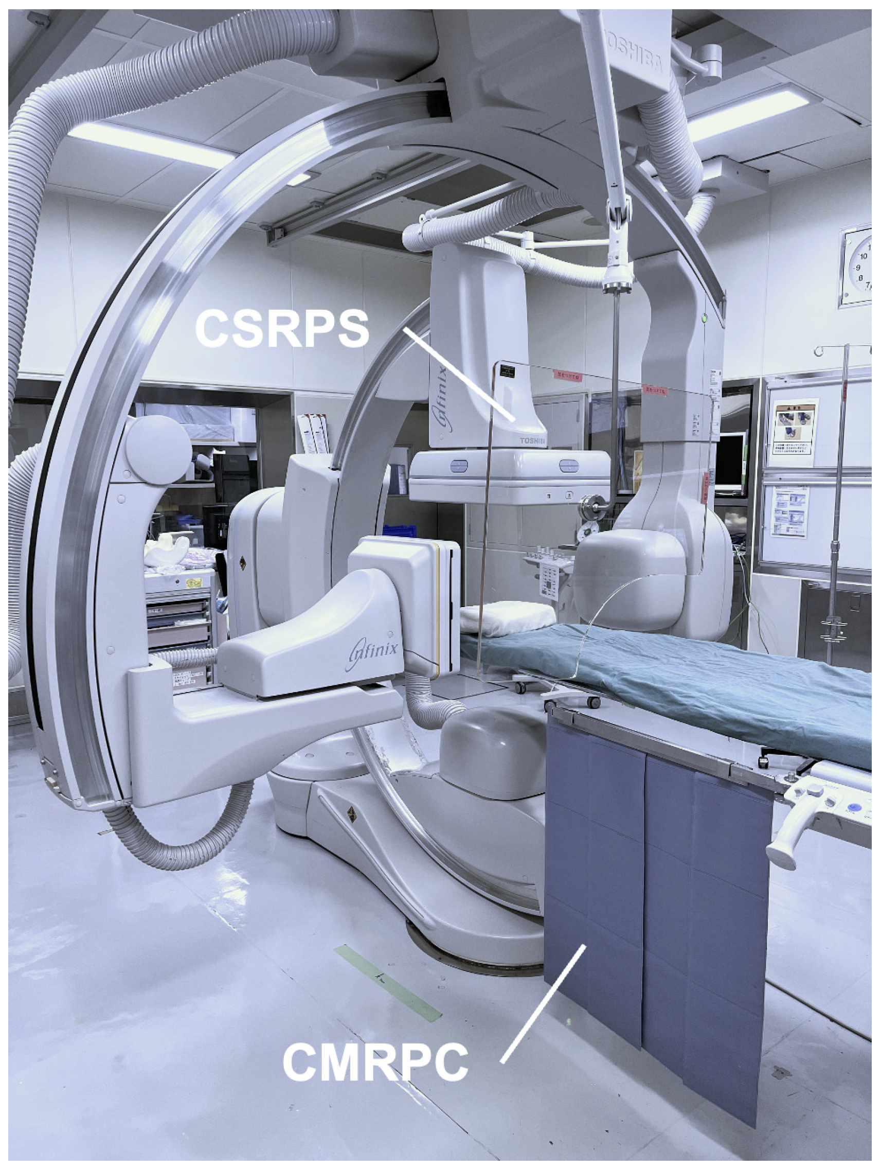
Figure 1. Biplane angiography system and radiation protective devices. CSRPS: ceiling-suspended radiation protective shield; CMRPC: couch-mounted radiation protective curtain.
Applsci 15 11584 g001
Figure 2. Placement of active personal dosimeters. Active personal dosimeters were attached (a) outside the lead thyroid protector at the left cervical region and (b) outside the lead apron at the left anterior chest. Devices are highlighted in red for clarity.
Applsci 15 11584 g002
Figure 3. Placement of staff and in-room monitoring cameras in the angiography suite. C1: camera 1; C2: camera 2. The suite was recorded simultaneously from two angles: C1 at the patient’s caudal side and C2 at the patient’s right side. GW: lead-containing glass window between angiography suite and control room; CSRPS: ceiling-suspended radiation protective shield; CMRPC: couch-mounted radiation protective curtain; RS: rolling lead shield; Ph1: main operator (first position); Ph2: assistant (second position); Ns: circulating nurse; Rt: radiological technologist.
Applsci 15 11584 g003
Figure 4. Operator’s main monitor screen. (a) Air kerma rate at the patient entrance reference point; (b) air kerma at the patient entrance reference point; (c) tube voltage, tube current, and pulse width during fluoroscopy; (d) tube voltage, tube current, and pulse width during radiography.
Applsci 15 11584 g004
Figure 5. Example of operator dose analysis during cerebral angiography. Plotted values are from the active personal dosimeter at the cervical region of Resident F (Case 2). Solid line: unprotected dose (µSv); ○: unprotected dose rate (mSv/h) during fluoroscopy; : unprotected dose rate during manual-injection angiography; : unprotected dose rate during automatic-injection angiography; ▼: time of CSRPS introduction.
Applsci 15 11584 g005
Figure 6. CSRPS placement and operator cervical/chest unprotected dose rate ratio. Box bot-tom/top: first/third quartiles; line: median; whiskers: minimum/maximum; ○: individual ratios. Mann–Whitney’s U test.
Applsci 15 11584 g006
Figure 7. Typical scene 1 (Case 5). CSRPS: ceiling-suspended radiation protective shield; CMRPC: couch-mounted radiation protective curtain. The right femoral puncture site was very close to the fluoroscopic field, so CSRPS was left beside the operator’s left shoulder and not correctly positioned. CMRPC was positioned appropriately. Projection: right anterior oblique. Devices highlighted in green for clarity.
Applsci 15 11584 g007
Figure 8. Typical scene 2 (Case 5). Scene 2 was similar to Scene 1. The CSRPS remained beside the operator’s left shoulder and was not correctly positioned; the CMRPC was positioned appropriately. Projection: left anterior oblique (LAO). Devices highlighted in green.
Applsci 15 11584 g008
Figure 9. Typical scene 3 (Case 3). CSRPS and CMRPC were used appropriately. Devices are highlighted in green.
Applsci 15 11584 g009
Figure 10. Typical scene 4 (Case 3). A gap remained between the lower edge of the CSRPS and the patient’s trunk; the CSRPS–operator distance was greater. CMRPC was positioned appropriately. Devices are highlighted in green.
Applsci 15 11584 g010
Figure 11. Typical scene 5 (Case 4). CSRPS and CMRPC were both inappropriately positioned. Devices are highlighted in green.
Applsci 15 11584 g011
Figure 12. Femoral arteriography [digital subtraction angiography (DSA)]. Rt-CFA: right common femoral artery; Rt-SFA: right superficial femoral artery; Rt-DFA: right deep femoral artery. DSA was performed after femoral puncture to confirm vessel course and detect vascular injury.
Applsci 15 11584 g012
Table 1. Operator unprotected dose per case of cerebral angiography without therapeutic intervention.
Case No.ProcedurePhysicianOperator QualificationPre-CSRPSEntire Procedure
Cervical
Unprotected
Dose (µSv)
Chest
Unprotected
Dose (µSv)
Cervical
Unprotected
Dose (µSv)
Chest
Unprotected
Dose (µSv)
1Post-procedural
diagnostic imaging
BSpecialist3.964.307.637.53
EResident19.2534.8829.3147.34
2Pre-procedural imagingCSpecialist14.7839.4529.05144.36
FResident84.03140.57148.98175.36
3Diagnostic imagingASpecialist9.9316.2633.5558.46
GResident18.7655.0649.3596.21
4Pre-procedural imagingCSpecialist24.8335.2185.28106.25
EResident94.9097.01164.88279.50
5Pre-procedural imagingASpecialist71.47167.4089.02198.85
GResident31.7142.2458.9494.76
6Pre-procedural imagingASpecialist11.2817.9621.0032.87
EResident38.2281.7549.10121.77
7Pre-procedural imagingBSpecialist36.2351.1760.9569.47
DResident47.4089.0673.15205.34
8Pre-procedural imagingDResident62.9585.3572.9396.82
FResident19.8773.6243.74105.20
9Pre-procedural imagingASpecialist20.2721.9631.6435.76
FResident77.57145.54102.22199.34
10Pre-procedural imagingCSpecialist5.643.3810.807.28
HResident24.8246.4539.0668.08
11Post-procedural
diagnostic imaging
BSpecialist2.944.1117.8058.75
HResident22.9644.7447.0970.67
12Post-procedural
diagnostic imaging
ASpecialist15.5817.5375.4485.34
FResident46.72121.5962.60149.10
mean ± SD33.59 ± 26.6459.86 ± 47.3358.48 ± 39.39104.77 ± 68.55
median [IQR]23.89 [15.38–46.89]45.60 [20.96–86.28]49.23 [31.06–73.72]95.49 [58.68–145.55]
range2.94–94.903.38–167.407.63–164.887.28–279.50
p-value (Mann–Whitney’s U-test)p = 0.053p < 0.01
Measured outside the lead apron and lead thyroid protector. CSRPS: ceiling suspended radiation protective shield; IQR: interquartile range.
Table 2. Relationship between operator unprotected dose per cerebral angiography case and operator position.
Case No.PhysicianCervical Unprotected Dose (µSv)Chest Unprotected Dose (µSv)
1st Position #12nd Position #21st Position #12nd Position #2
1B-7.63-7.53
E29.31-47.34-
2C2.9826.0764.5679.80
F120.2628.72163.8311.53
3A10.9222.6330.1728.29
G34.0615.2984.6811.53
4C25.1560.1352.9653.29
E136.4328.45251.6227.88
5A70.1718.85172.6526.20
G39.3619.5866.2828.48
6A-21.44-32.87
E49.10-121.77-
7B33.1627.7935.8133.66
D51.4621.69200.824.52
8D53.4319.5073.7323.09
F41.142.60102.342.86
9A5.6925.954.7631.00
F100.701.52198.071.27
10C-10.80-7.28
H39.06-68.08-
11B10.836.9723.9934.76
H47.09-70.67-
12A56.3319.1163.8821.46
F55.467.14141.347.76
mean ± SD 48.19 ± 35.0319.59 ± 12.8697.11 ± 66.8823.75 ± 18.98
median [IQR] 41.14 [29.31–55.46]19.54 [10.01–25.98]70.67 [52.96–141.34]24.65 [7.70–31.47]
range 2.98–136.431.52–60.134.76–251.621.27–79.80
p-value
(Mann–Whitney’s U-test)
p < 0.01p < 0.01
#1 Primary operator’s position. #2 Assistant’s position; IQR: interquartile range; -: the operator did not change position during the procedure or was not in the position because they were in the control room.
Table 3. Effect of CSRPS placement on operator unprotected dose rate.
RaySafei3 PlacementCSRPS
Placement
No. of ScenesOperator Unprotected
Dose Rate (mSv/h)
p-Value (Mann–Whitney U Test)
Median [IQR]Range
CervicalAppropriate40.65 [0.53–0.79]0.48–0.87p < 0.01
Inappropriate392.20 [1.54–2.88]0.41–4.69
ChestAppropriate42.05 [1.60–2.54]1.45–2.80p = 0.917
Inappropriate392.04 [1.49–2.66]0.70–5.08
CSRPS: ceiling suspended radiation protective shield; IQR: interquartile range.
Table 4. Operator unprotected dose-rates and dose-rate ratios in five typical scenes.
Typical
Scene No.
Case No.DSA SiteX-Ray ProjectionFPD Size (inch)SID (cm)Ka,r (mGy)Table Height (cm)Cervical Unprotected Dose Rate (mSv/h)Chest
Unprotected Dose Rate (mSv/h)
Cervical/Chest Unprotected Dose Rate Ratio
15Rt FAGFrontal—RAO 16°, Caudal 1°129062.8795.1611.750.44
25Rt FAGFrontal—LAO 20°, Cranial 0°129070.48711.2935.270.32
33Lt C-CAGFrontal—LAO 0°, Cranial 1°129080.06930.481.650.29
Lateral—RAO 90°, Cranial 0°12111100.1
43Lt SAGFrontal—LAO 0°, Cranial 0°129193.2941.013.200.32
Lateral—RAO 90°, Cranial 0°12112107
54Lt C-CAGFrontal—LAO 0°, Caudal 2°129653981.177.640.15
Lateral—RAO 90°, Cranial 0°1211960.8
Rt: right; Lt: left; C-CAG: common carotid artery angiography; SAG: subclavian artery angiography; DSA: digital subtraction angiography; RAO: right anterior oblique; LAO: left anterior oblique; FPD: flat panel detector; Ka,r: air kerma at the patient entrance reference point.
Table 5. Four practical points for radiation protective device use in cerebral angiography.
1Place CSRPS between the scatter source and the operator’s eyes
2Position CSRPS as close to the operator as possible
3Eliminate gaps between the lower edge of the CSRPS and the patient’s trunk
4Place CMRPC between the scatter source and the operator’s lower body
Disclaimer/Publisher’s Note: The statements, opinions and data contained in all publications are solely those of the individual author(s) and contributor(s) and not of MDPI and/or the editor(s). MDPI and/or the editor(s) disclaim responsibility for any injury to people or property resulting from any ideas, methods, instructions or products referred to in the content.