Abstract
In this study, the thermal and structural behavior of battery module components produced from polymer-based composites was systematically evaluated using coupled Moldflow 2016 and ANSYS Fluent 2024 simulations. Three thermoplastics—metal-flake-reinforced PC+ABS (Polycarbonate/Acrylonitrile Butadiene Styrene), carbon-fiber-reinforced PEEK (Polyether Ether Ketone), and hybrid mineral-filled PP (Polypropylene)—were investigated as alternatives to conventional aluminum components. Moldflow simulations enabled the assessment of injection molding performance by determining injection pressure, volumetric shrinkage, warpage, residual stress, flow front temperature, and part weight. PEEK exhibited the best dimensional stability, with minimal warpage and shrinkage, while PP showed significant thermomechanical distortion, indicating poor resistance to thermally induced deformation. For thermal management, steady-state simulations were performed on a 1P3S pouch cell battery configuration using the NTGK/DCIR model under a constant heat load of 190 W. Material properties, including temperature-dependent thermal conductivity, density, and specific heat capacity, were defined based on validated databases. The results revealed that temperature distribution and Joule heat generation were strongly influenced by thermal conductivity. While aluminum exhibited the most favorable thermal dissipation, PC+ABS closely matched its electrical performance, with only a 1.3% lower average current magnitude. In contrast, PEEK and PP generated higher cell core temperatures (up to 20 K) due to limited heat conduction, although they had comparable current magnitudes imposed by the energy-conserving model. Overall, the findings indicate that reinforced thermoplastics, particularly PC+ABS, can serve as lightweight and cost-effective alternatives to aluminum in mid-range battery modules, providing similar electrical performance and thermal losses within acceptable limits.
1. Introduction
Electric vehicles and highly integrated microelectronics require advanced thermal management solutions to ensure safe and efficient operation. This demand necessitates not only the development of novel materials, such as thermally conductive polymer composites and multifunctional structures, but also the design and optimization of battery thermal management systems (BTMSs) alongside safety-oriented multiphysics modeling. On the manufacturing side, process improvements such as injection–compression molding and conformal cooling channels play a critical role in enhancing dimensional stability and reducing cycle times [1]. In this context, Tarannum et al. reported that in an expanded graphite (EG)/polyetherimide (PEID) composite produced via solution mixing, the three-dimensional morphology of EG was preserved, forming a continuous conductive network, which resulted in outstanding electrical conductivity and a thermal conductivity of 7.3 W/mK [2]. Similarly, Goli et al. demonstrated that incorporating graphene into phase change materials (PCMs) can enhance thermal conductivity by orders of magnitude while maintaining latent heat storage capacity, thereby significantly improving battery thermal management [3]. As highlighted by Azzopardi et al., such material-driven advancements point to a broad design space in battery packs in which material selection, structural optimization, and system integration collectively determine the balance of performance, safety, and sustainability [4]. In contrast, Tan and Zhang emphasized that although thermally conductive polymer composites (TCPCs) offer advantages such as low density and processability, their lower-than-expected thermal conductivity values remain a major challenge, which must be addressed through interfacial engineering and filler architecture [5]. From a manufacturing perspective, injection molding (Figure 1) has been shown to reduce filling pressure and minimize shrinkage/warpage, thereby enhancing dimensional stability in thin and large components; Kwon et al. further demonstrated that small parting-line gaps significantly improve final geometric accuracy [6].
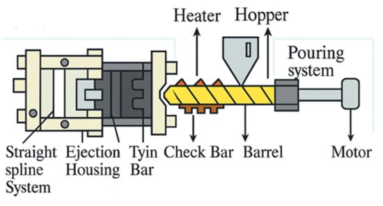
Figure 1.
Injection-molding machine parts.
For a reliable numerical representation of these processes, Baum et al. systematically reviewed the evolution of filling phase models from 1D to 3D, stressing the critical importance of accurate rheological characterization [7]. At the system level, Khan et al. proposed comprehensive guidelines for designing battery thermal management systems (BTMSs) that comply with existing quality and safety standards [8], while Murugan et al. compared air, liquid, and PCM-based thermal management systems (TMSs), showing that innovative materials and smart control algorithms play a pivotal role in next-generation EV applications [9]. Meanwhile, Reghunath et al. used ANSYS Fluent simulations to show that cooling channels play a delaying and limiting role in thermal runaway propagation, highlighting their critical contribution to safe battery pack design [10]. Multifunctional composites also provide new opportunities for the integrated optimization of thermal, mechanical, and energy storage functions. Pejman et al., for instance, combined structural battery composites with micro-channeled composites in a multiphysics framework, simultaneously maximizing energy storage and thermal regulation while achieving 23% range extension [11]. In high-power pouch modules, He et al. developed a coupled fluid–solid “bathtub-type” liquid cooling geometry, which maintained maximum temperatures below 60 °C while achieving excellent temperature uniformity [12]. At the component level, Chiang and Chang employed response surface methodology (RSM) to optimize injection molding parameters (Figure 2), reducing shrinkage and warpage in PC/ABS components by 37.8% and 53.9%, respectively [13]. Hassan et al. showed that positioning the gate normal to thin wall sections shortened solidification time and improved dimensional stability [14]. From a safety perspective, Piccirillo et al. developed an electrothermal coupled model for pouch cells, emphasizing that accurate representation of temperature-dependent reactions is essential for understanding thermal runaway [15]. Complementarily, Joe and Yoo analyzed overcharge and overheating experiments using Gaussian-based deconvolution and Arrhenius kinetics, modeling the multi-stage exothermic processes involved [16]. For intra-cell thermal dynamics, Wakale et al. compared the Equivalent Circuit Model (ECM) with the Newman–Tiedemann–Gauthier–Kim (NTGK) model, assessing their predictive accuracy for temperature, voltage, and heat generation under varying C-rates [17].
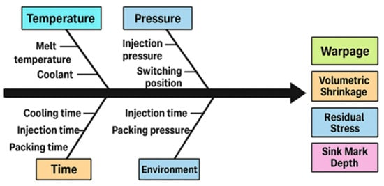
Figure 2.
Workpiece quality parameter relationship schematic.
At the material level, Vaidya and Chawla investigated thermal expansion in fiber- and particle-reinforced metal matrix composites (MMCs), showing reinforcement-type-dependent residual strains during cooling [18], while Shang and Wang developed a theoretical model demonstrating that residual stresses in solid-state half-cells can enhance capacity but reduce mechanical reliability [19]. At the design optimization scale, Amrit et al. employed multi-objective genetic algorithms (MOGAs) combined with surrogate models to efficiently explore trade-offs between cost, weight, and structural strength in battery tray design [20]. In a review of a BTMS (battery thermal management system), Xu et al. emphasized that hybrid and data-driven designs are key to improving safety and efficiency [21]. In polymer blends, compatibilization remains critical; Anjos et al. showed that maleic anhydride-grafted ABS (ABS-g-MA) improves phase compatibility and dispersion in PC/ABS systems [22]. Recent advances in organic polymer thermoelectric composites have also demonstrated the potential of these materials for efficient energy conversion and local cooling, owing to their low density, low thermal conductivity, and flexibility [23]. In parallel, Wang et al. developed and validated an electrochemical–thermal coupled model, which systematically analyzed the influence of electrochemical and thermal parameters on battery performance and temperature evolution, thereby providing a reliable tool for battery thermal management studies [24]. In terms of modeling and parameter sensitivity, Parmar et al. extracted total and ohmic heat generation and temperature fields from Fluent simulations, providing key data for cooling design [25]. Similarly, Wang et al. validated an electrochemical–thermal coupled model with experimental data, demonstrating the quantitative effects of electrode properties and heat transfer parameters on voltage, temperature, and capacity [24]. In addition, Kim et al. showed that the time-dependent viscoelastic behavior of thermal interface materials (TIMs) alters contact pressure and thermal contact conductance, impacting the long-term reliability of cooling systems [26]. At the pack topology level, Yu et al. mathematically analyzed how module collector positions affect equivalent resistance and current distribution, demonstrating that symmetric multi-collector configurations improve current homogeneity in edge modules [27]. Furthermore, Tan et al. used a COMSOL 2016-based electrochemical–thermal model to confirm that polarization heat dominates total heat generation and that ambient temperature strongly influences increases in battery temperature [28]. Cooling channel geometry is a decisive factor in productivity and quality. Kumar and Mishra showed that conformal cooling channels significantly influence cycle time and thermal performance in injection molding [29].
Multi-scale thermo–electromechanical finite element (FE) models developed by Ling et al. successfully predicted short-circuit and crash responses from the cell to full-vehicle scale, providing valuable tools for battery electric vehicle (BEV) safety assessment [30]. On the tooling side, Lee’s computer-aided engineering (CAE) analyses optimized gate design to reduce flow imbalance and deformation [31], while Hentati et al. applied the Taguchi method to confirm that injection pressure is the most influential factor in shear stress, reducing molding defects [32]. In insulation-oriented composites, Melnyk optimized filler type, fraction, and interfacial interactions to achieve ultralow thermal conductivity of 0.173 W/m·K [33]. Similarly, Hopmann et al. applied a homogenization-based approach to long-fiber thermoplastics (LFTs), predicting the effects of fiber length distribution on creep and relaxation [34]. The importance of thermal history was reinforced by Peyser and Bascom, who showed that filler type and cooling rate jointly affect glass transition temperature (Tg), with equivalent directionally opposite outcomes [35]. In joining applications, Li et al. demonstrated that lower cooling rates in resistance-welded carbon fiber/PEEK joints increase crystallinity and shear strength (up to 28%), with transcrystallinity playing a decisive role [36]. Regarding electromagnetic interference (EMI), Kashimatt et al. highlighted that three-dimensional printed multilayer conductive polymer composites can achieve up to 82% higher shielding effectiveness (SE) compared to conventional molded counterparts, indicating their promise for aerospace and defense applications [37].
Regarding mold technologies and predictive modeling, Lyubimyy et al. optimized conformal cooling channels in metal–polymer layered molds, improving both heat flow and structural durability [38]. Likewise, Gámez et al. processed Moldflow simulation data through an artificial neural network (ANN), predicting and optimizing warpage in polypropylene parts with high accuracy and speed [39]. At the system integration level, Siddiqui et al. emphasized that polymer composite battery housings are good alternatives to conventional materials due to their light weight, mechanical robustness, and safety [40]. In EV motors, Madeshwaran et al. combined lumped-parameter thermal network (LPTN) modeling with computational fluid dynamics (CFD), developing a hybrid simulation method that optimized cooling system performance while ensuring safe operation and improved torque/power density [41]. Regarding material selection, Kulkarni et al. compared air-, liquid-, and PCM-based cooling methods in battery pack casings, stressing that material choice must align with climate conditions and BTMS requirements [42]. Thirumurugan showed that adding graphite filler to PC/ABS improves tensile and flexural moduli by up to 20%, although tensile strength and elongation decrease slightly, offering a balanced option for automotive parts [43]. In metal injection molding (MIM), Osada and Kobayashi fabricated Cu/carbon fiber composites and revealed that fiber content and orientation strongly affect mechanical performance [44]. Guo et al. reviewed molding methods for PEEK and its composites, noting their strategic potential to replace metals despite processing challenges posed by semicrystallinity and high melting temperature [45]. Finally, Wolfsgruber et al. showed that filler volume fraction, particle shape, and intrinsic conductivity are the most critical factors determining thermal performance in thermoplastic composites [46], while Guerreiro et al. demonstrated that PA12/carbon nanotube (PA12/CNT) nanocomposite cables can partially replace metallic shielding, reducing cable weight by 4–20% while ensuring adequate EMI protection [47]. At the system level, Ranjbaran et al. proposed a hybrid BTMS combining PCM and cold air ducts, achieving a maximum temperature ≈ 314 K and cell-to-cell temperature difference (≈1.6 °C [48]. Lastly, Li et al. developed a three-dimensional electrothermal model for a 20 Ah polymer cell, showing that low short-circuit resistance leads to intense local heat generation, while higher through-plane conductivity and mini-channel cooling significantly reduce maximum temperature and limit hot spot propagation [49]. More recently, Yu et al. introduced a novel flame-retardant composite PCM formulation that effectively minimizes leakage (<1%) and significantly enhances thermal safety, maintaining the maximum temperature of battery packs below 50 °C even under high discharge rates [50]. Complementarily, studies integrating PCMs with forced-air convection have demonstrated that such hybrid systems successfully overcome the heat accumulation issues inherent to passive PCMs, ensuring that the maximum temperature remains under 50 °C and improving temperature uniformity across cycles [51].
Numerous multi-physics simulation studies on the thermal management of battery modules have been reported in the literature. However, most of these works primarily focus on thermal behavior alone or remain limited to a specific type of material. The innovative aspect of this study is that, although it does not directly propose a theoretical model, it provides an integrated evaluation of the manufacturability, thermal performance, and electrical behavior of different polymer composites (PC+ABS, PEEK, and PP) through a combined Moldflow and Fluent-based simulation approach. With this approach, thermal management, in-mold stresses, deformation tendencies during injection molding, and electrical properties are analyzed together in a multidimensional assessment. PC+ABS, PEEK, and PP composites were selected for study due to their widespread investigation in the literature for lithium-ion battery applications and their practical availability in industry. Specifically, PC+ABS is distinguished by high impact resistance and broad engineering use, PEEK is preferred in critical applications due to its high temperature resistance and chemical stability, and PP stands out as a potential lightweight material for battery modules due to its low density, low cost, and ease of processing. Given their properties, these three polymer materials were considered suitable candidates for comparison with aluminum in terms of both manufacturability and performance. Aluminum was chosen as the benchmark for comparison because it is currently among the most widely used structural materials in lithium-ion battery modules. Its high thermal conductivity (167 W/m·K) contrasts highly with that of polymers (~0.2–0.3 W/m·K). Although this difference does not imply direct performance equivalence, it facilitates assessment of the light weight, cost, and processability advantages of polymer-based alternatives against the current industrial standard of aluminum. This work is a preliminary numerical study, which relies on numerical modeling approaches rather than experimental validation. The Moldflow and Fluent models employed are based on widely validated methodologies in the literature. The main contribution of this study is the multidisciplinary evaluation of different polymer composites in terms of both production behavior (injection molding) and operational performance (thermal–electrical properties).
In light of the growing demand for thermally and electrically efficient battery enclosures, this study investigates the performance of injection-molded, metal-filled polymer composites as potential alternatives to conventional aluminum in pouch-type lithium-ion battery modules. A comprehensive numerical approach was adopted, combining Moldflow-based injection-molding simulations with ANSYS Fluent thermal–electrical analyses. Key parameters such as warpage, volumetric shrinkage, flow front temperature, and residual stress were measured to assess manufacturability, while current magnitude, static temperature distribution, and total heat generation were used to evaluate operational performance. By directly comparing these results with those of aluminum, the study aims to quantify the trade-offs and feasibility of implementing lightweight polymer-based solutions in structural and thermally active battery environments. The findings offer new insights into multiphysics design optimization for advanced battery systems.
2. Materials and Methods
2.1. Material
In this study, three different reinforced thermoplastic composite materials that can be used in battery cooling module components were chosen. The materials were selected from the material database of Autodesk Moldflow Insight Ultimate 2016 software by considering the following criteria: mechanical stiffness, thermal stability, moldability, and lightness. The first material is PC+ABS (metal-flake-filled), referred to by the trade name Cycoloy C1200HFM (SABIC Innovative Plastics US, LLC, Houston, TX, USA), which is reinforced with metal particles at a rate of 10% (Figure 3a). This material, which has high impact resistance and good molding and surface quality, is widely preferred in the automotive and electronic sectors. Given its lower filling time and low-viscosity properties, this material is favorable in terms of mold efficiency.
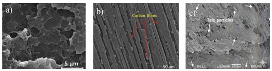
Figure 3.
SEM microstructure view of polymer composites (a) PC+ABS22, (b) PEEK23, and (c) PP24.
The second material is a high-performance engineering thermoplastic, PEEK, which is a special composite structure reinforced with 10% carbon fiber, 10% graphite, and 10% PTFE (Teflon) (Figure 3b). This material is listed in the database under the trade name Luvocom 1105/CF/10/GR/10/TF10 (Lehmann & Voss & Co, Hamburg, Germany). Although its thermal conductivity is about 0.29 W/m·K, the thermal and carbon and graphite reinforcements facilitate a more balanced heat distribution than in conventional plastics with thermal conductivity. Its high sensitivity to fiber orientation provides directional mechanical properties. Thus, PEEK is a viable alternative for battery module components that operate under high temperatures and stress. The third material is a composite made of a polypropylene (PP) matrix containing 9% metal whisker and 3% talc filler (Figure 3c). This material, which is registered in the Moldflow database under the name HX320 (Hyundai Engineering Plastics Co. Ltd., Seoul, South Korea), is characterized by its low cost, ease of processing, and light weight. These three materials were selected for inclusion in this study to compare their behavior in injection molding and their thermal management potential, as well as to evaluate their performance in terms of engineering criteria. Each material’s mechanical, thermal, and moldability properties are detailed in Table 1. In summary, the three primary composite materials employed in this study (PC+ABS, PEEK, and PP) are widely used in the automotive and electronics industries, and their distinct thermal and mechanical properties make them strong candidates for use in battery modules. PC+ABS was selected for its impact resistance and dimensional stability, PEEK was selected for its high thermal endurance and chemical resistance, and PP was selected for its low density and cost-effectiveness. The comparison among these materials reveals the performance boundaries of different polymer-based alternatives. The central focus of this study is to assess the potential of polymers against aluminum, a widely used reference material. This approach contributes to a clearer understanding of both the advantages and limitations of polymers.

Table 1.
SEM microstructure view of polymer composites: (a) PC+ABS; (b) PEEK; (c) PP.
2.2. Model and Process Parameters
The injection mold model used in this work was designed for the production of pouch-type battery module components (cell holder structure, tab connection, and carrier skeleton) (Figure 4). A model was created in Solidworks 2020 software, converted to STL format, and integrated into simulations. The model pouch cell had a total length of 116 mm, a cell length of 100 mm, and a base length of 20 mm, and the injection channel was a centrally fed single-channel (sprue-fed) system. The busbar width was 30 mm, the cell width was 100 mm, and the model consisted of 3 cells, each with a thickness of 5mm. Cooling channels were symmetrically placed around the model, and it was assumed that a coolant of constant temperature passed through them.
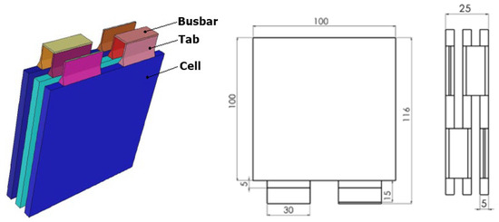
Figure 4.
Schematic of battery model and technical dimensions.
To accurately represent the interior volume of the material, a mesh structure consisting of three-dimensional (3D) tetrahedral elements was created with Moldflow Insight 2016 software. To improve the accuracy of volumetric modeling, six-layered optimization regions were defined. The mesh model consisted of 14,738 elements and 7371 nodes. When evaluated in terms of quality criteria, an aspect ratio of 1.57, a match percentage of 98.5%, and a reciprocal percentage of 99.4% were obtained. This design provided a very detailed solution in regions in which the material flow was the critical factor.
The point of injection is a critical issue in terms of both molding quality and product integrity. In this study, flow resistance indicator and gating suitability simulations were used for gate location optimization. In the analysis, regions with low flow resistance were identified as suitable gate areas for homogeneous filling. In the gate location analyses, variables such as gate diameter, flow time, and pressure distribution were considered, and flow differences depending on material viscosity were observed.
2.3. Injection Parameters and Process Design
In this study, the Design of Experiments (DOE) method was applied to investigate the influence of melt temperature in the injection molding process on mold filling, warpage, residual stresses, and production efficiency. For this purpose, the Face-Centered Central Composite Design (FCCCD) approach was implemented in Autodesk Moldflow Insight 2016 software, and analyses were performed with three level temperature sets for each material (Table 2). The regression distribution of process outputs was obtained. Linear and quadratic effects were observed, and statistically optimum melt temperatures were identified. The temperature levels for each material are listed below.
Table 2.
Melt temperature parameter levels.
The DOE study results provided findings that enabled the determination of the optimum temperatures specific to each material. At these temperatures, the lowest warpage, minimum residual stress, and energy-efficient production conditions were obtained. This research offers a significant decision support tool for optimizing material choice in injection molding by providing a direct comparison of the production behavior of different composite polymers.
According to the ANOVA results (Table 3), the regression models obtained for all materials are significant at the 95% confidence level. For example, the PEEK regression model is significant with F = 103.29 and p = 1 × 10⁻⁵, which means that melt temperature is the most important factor controlling volumetric shrinkage, with 99% confidence. Similarly, F = 81.77 and p = 2.1 × 10⁻⁵ and F = 92.13 and p = 1.4 × 10⁻⁵ for the PC+ABS and PP materials, respectively. These results indicate that the melt temperature has a significant effect on volume contraction not only with linear regression but also with the second degree of impact and that the FCCCD approach is a reliable model for determining material behavior.
Table 3.
ANOVA results for volumetric shrinkage (PEEK).
Bland–Altman analyses (Figure 5) were also performed to investigate consistency between the experimental and model predictions; for all materials, the observations were within the ±1.96 SD limit, which indicates that the regression models were sufficiently accurate in predicting volumetric shrinkage.
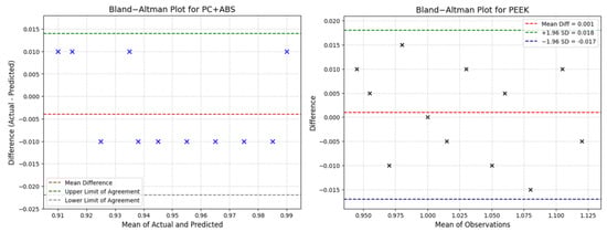
Figure 5.
Bland–Altman plots showing the agreement between actual and predicted values.
3. Mold-Filling Simulation
Fill analyses of the mold were carried out utilizing Autodesk Moldflow Insight software. A fixed mesh structure and the injection mold geometry were employed for each material for one-to-one comparative simulations. The goal was to analyze the effects of process outputs on the variable melt temperature throughout the process. Figure 6 presents the step-by-step simulation process in the form of a flowchart.
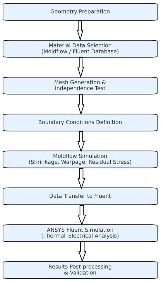
Figure 6.
Schematic representation of the simulation workflow.
3.1. Injection Pressure
The injection pressure directly affects the polymer’s ability to fill the mold cavity and is a primary influencing parameter in a wide range of areas, ranging from product geometry to energy consumption. It is directly correlated with the viscosity of the material used, the flow behavior, the mold geometry, and the melt temperature and therefore varies. Figure 7a–c show that each of the three materials, in different temperature ranges, exhibited different injection pressure profiles. The injection pressure data obtained indicate that the pressure requirement decreases in all materials with an increase in melt temperature. For PC+ABS, this is an effect of the amorphous structure, which results in a decrease of 18 MPa at 308 °C from about 9 MPa due to the increase in temperature. This decrease is related to an increase in the mobility of molecular chains with temperature and the consequent decrease in viscosity. Due to its crystalline structure, PEEK initially requires a high pressure of about 35 MPa; however, at about 400 °C, this value decreases to 26 MPa. This behavior can be explained by PEEK’s high melting point and the gradual disappearance of viscosity resistance during the phase transition from solid to liquid. The injection pressure in materials with low crystallinity and a low melting temperature, like PP, was also reduced; it decreased from about 6.6 MPa to 4.6 MPa due to the low friction forces in the system.
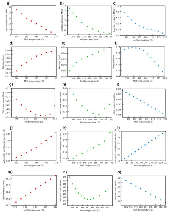
Figure 7.
Moldflow simulation results, showing the variation with melt temperature for different polymer composites (red: PC+ABS; green: PEEK; blue: PP); (a–c): Injection pressure; (d–f): Warpage; (g–i): Wall hear stress; (j–l): Voumetric shrinkage at ejection; (m–o): Residual stress.
3.2. Warpage
Warpage refers to shape deformations in the geometry of a part due to internal stresses during cooling [7]. Figure 7d–f shows the nature of the relationship between the dimensional stability and melt temperature of each material, parameters that correspond to specific characteristics. PP showed a trend of warpage (0.735 mm) that reached its maximum value around a melt temperature of 200 °C and then dramatically decreased with an increase in temperature. This reveals that at low temperatures, due to its low mechanical rigidity and high coefficient of thermal expansion, PP is more prone to losing its dimensional stability. The outcomes for PEEK demonstrate that this material is suitable for engineering applications that require at high temperatures; it shows very low and linearly increasing warpage values (0.180–0.205 mm) throughout the entire temperature range, which are very similar to the values obtained at low temperature. This behavior is consistent with PEEK’s crystalline structure, high heat resistance, and low thermal deformation tendency. Regarding PC+ABS, warpage increases until 295 °C from 264 °C and, after this point, shows a decreasing tendency. This means that PC+ABS is amorphous within a certain temperature range due to the balancing of internal stresses that are being resolved, which improves its dimensional stability.
These analyses clearly demonstrate that the materials used in battery module components must be mechanically and thermally resistant and should be carefully evaluated for their dimensional stability. PEEK demonstrates optimum performance in geometrically precise areas, such as the cell socket, tab, or cooler support, thanks to its low deformation rate even at high temperatures, making it particularly suitable for use in these areas. PEEK’s resistance to deformation is related to its crystalline structure and high thermal stability. In contrast, PP, which is characterized by its low production cost and ease of processing, offers limited applications in battery assembly systems, which require good structural tolerance due to high distortion values.
PP may only be suitable for secondary components that are fixed on surfaces and not exposed to heat. PC+ABS does not compare to PEEK in terms of thermal deformation; however, due to its balanced behavior and impact resistance, it is a good option, especially for battery housing covers or connection elements that are exposed to medium temperatures. In conclusion, the material selection should not only depend on the ease of processing but should also consider how the material will contribute to the long-term structural integrity of the battery system. In this context, the data obtained in the study are directly transferable to engineering decision-making processes. The behaviors noted are visually corroborated by the warpage contour results shown in Figure 8.
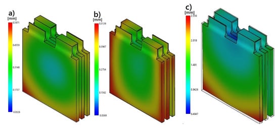
Figure 8.
Moldflow warpage contour results for (a) PC+ABS; (b) PEEK; (c) PP.
3.3. Wall Shear Stress
Shear stress created on the surface of the mold walls due to the flow of material inside the mold is one of the main parameters directly affecting both wear on the mold and the surface quality of the part. For PC+ABS, a clear trend of decreasing wall shear stress due to increasing melt temperature was observed; at 268 °C, the value was about 0.325 MPa, and at 298 °C, it reached a minimum (0.14 MPa). After this point, however, a slight increasing trend emerged (Figure 7g), and the stresses applied to the mold surface became more homogeneous due to the heat. A similar trend but with higher values was observed for PEEK: the wall shear stress at 360 °C of approximately 0.6 MPa dropped to a minimum (0.51 MPa) at 390 °C due to the increase in temperature, after which it rose again (Figure 7h), showing a strong interaction with the processing parameters.
For PP, the wall shear stress linearly decreased in the range of 180–220 °C, dropping from 0.095 MPa to 0.06 MPa (Figure 7i). Such results are particularly significant in battery module production, as mold geometry is sensitive to changes in wall smoothness, stress accumulation, and surface quality. Although low wall shear stress facilitates detachment of the material from the mold, very low values may result in potential surface defects or incomplete fillings. In this context, although PEEK is recommended for applications that require high strength, PC+ABS can provide more stable surface quality by offering controlled slip conditions. When used in fast production cycles, PP, with its low viscosity, applies less stress to the mold walls, resulting in energy-saving benefits and lengthening the life of the mold.
3.4. Volumetric Shrinkage
Volumetric shrinkage is an important parameter in injection molding processes and has a direct impact on the dimensional accuracy of the part, as well as the distribution of residual stresses. Our results indicate that an increase in melt temperature leads to volumetric shrinkage in all materials in a positive direction; however, the intensity and character of this increase depend on the thermal and molecular properties of the material (Figure 9). PC+ABS is a polymer with an amorphous structure and therefore does not exhibit crystallization [23].
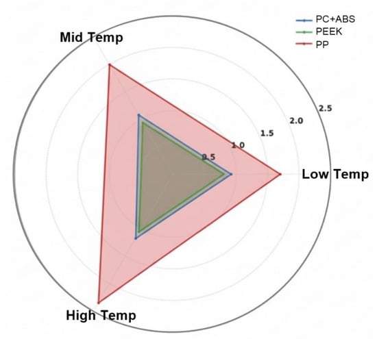
Figure 9.
Comparison of volumetric shrinkage (%) at low, mid, and high melt temperature levels for different polymer composites.
The results show that in a temperature range from 268 °C to 308 °C, volumetric shrinkage has a linear increasing trend from around 0.92% to 1.17% (Figure 7j). At high temperatures, a molten material with lower viscosity could flow more easily in the mold, but during cooling, the chains freeze irregularly in a random manner, which results in the formation of internal voids due to empty spaces in the material. At the same time, the fact that PC+ABS operates around the glass transition temperature of the material also causes a rapid volume change during the cooling process; thus, more shrinkage occurs when it is removed from the mold.
PEEK is a semi-crystalline polymer with a high melting temperature and excellent dimensional stability. In the temperature range 360 °C to 400 °C, PEEK shows distinct and non-linear volumetric shrinkage, which is clearly shown by an increase in the graph (Figure 7k). The initial value at around 0.825% increases almost to 1.07% when the temperature reaches 400 °C. This increase is mainly due to microscopic condensations resulting from crystal growth with temperature and the increase in crystallinity in the material. During cooling at high temperatures, crystal nucleation becomes more evident, and the influence of these structures on the casting shrinkage will be greater. In addition, for PEEK, the viscosity is very high at low shear rates, which causes the heat gradients inside the material to dissipate slowly. This intensifies thermal shrinkage due to the slow diffusion of the heat gradients. PP is a polymer with a low density and crystalline structure [24]. The graph obtained (Figure 7l), shows that a temperature increase from 180 °C to 220 °C results in volumetric shrinkage from about 1.7% to approximately 2.35%. These tendencies are consistent with the high thermal expansion coefficient and low viscosity of PP. The chain structure of PP becomes more mobile with an increase in temperature, and in-mold crystallization finishes relatively quickly. During solidification, this causes the chains to be packed more tightly and results in high volume losses. In addition, due to PP’s low glass transition temperature results in a stronger tendency for volumetric contraction in the cooling phase.
The graphs in Figure 10 represent three different thermoplastic polymer materials—PC+ABS (amorphous structure), PEEK (semi-crystalline structure) and PP (low crystallinity tendency)—and clearly show their different responses to warpage and residual stress due to changes in melt temperature. These differences result from the nature of each polymer chain’s structure, phase behavior, heat conduction characteristics, and the microstructures developed during cooling. PC+ABS is an amorphous material that does not crystallize, and its chains are irregularly distributed.
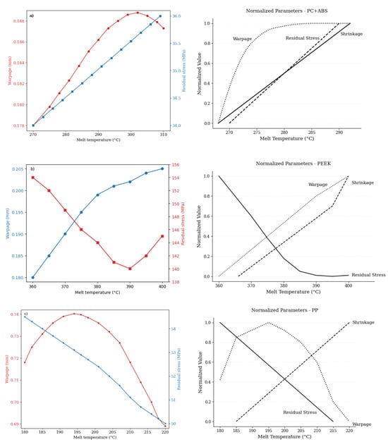
Figure 10.
Variation of warpage (mm) and residual stress (MPa) as a function of melt temperature (°C) for different polymer composites (a) PC+ABS; (b) PEEK; (c) PP.
Increasing the melt temperature in this material leads to chain mobility, which results in a decrease in viscosity [22]. This means that the polymer will flow more easily in the injection mold, but it will also become more sensitive to temperature gradients. As a result, warpage values, depending on the flow direction of the polymer, will increase due to the asymmetric distribution of thermal shrinkage. Residual stress increases linearly with temperature due to rapid rotation of the chains and irregular freezing in the internal structure, which causes stress accumulation (Figure 10a). The drop and subsequent increase in the residual stress curve can be explained by PEEK’s crystallization kinetics: in the temperature range of 380–390 °C, optimal crystal growth and stress relaxation are observed in the inner structure (Figure 10b). In this case, the crystallization of PEEK is definitely the major factor affecting residual stresses. PP, which has a low melting temperature and high fluidity, is a material whose viscosity is extremely sensitive to temperature.
3.5. Residual Stress
The formation of residual stress is directly related to the thermal transition behavior of the material used in the injection molding process, the viscosity profile, and the cooling dynamics. For PC+ABS, residual stress showed a linear increase with the increase in melt temperature (Figure 7m). This is because at high temperatures, the amorphous PC+ABS interacts more with the mold surface, thus cooling slowly and, at the same time, increasing thermal gradients in the inner structure. The PEEK material also exhibits more complex behavior due to its crystalline structure and high melting temperature (Figure 7n). The maximum residual stress (154 MPa) was recorded at 360 °C; it decreased to a minimum at around 385 °C and then began to rise again. This parabolic trend is the result of PEEK’s temperature-dependent crystallization kinetics. Within a specific temperature range, the crystal structure becomes more homogeneous, and thus, less internal stress occurs. However, with an increase in temperature (Figure 7o), while the viscosity decreases to very low levels, new areas of tension are generated in the mold due to the effects of rapid injection and abrupt cooling. The data for PP indicate that the residual stress decreases in a regular manner as the temperature rises due to PP’s low viscosity and high chain mobility. This trend is similar to PP’s viscosity-shear rate behavior; even at low temperatures, PP exhibited high flowability, so that viscosity changes during cooling became more homogeneous, limiting the accumulation of residual stress was limited. Consequently, in battery modules that typically require thermal stability, processing PEEK in a controlled temperature range results in minimum residual stress and dimensional stability, while PP, with its low stress trend, is suitable for economic and mass production applications with an appropriate profile. Due to its viscosity sensitivity and very high thermal expansion, processing PC+ABS requires temperature control. Therefore, when selecting a material, the potential for residual stress should be considered in addition to the material’s mechanical and thermal properties.
3.6. Part Weight
In injection-molding processes, part weight is a key indicator of not only material consumption but also the quality of filling in the mold and the geometric stability of the final product. According to numerical data; the weight of the PC+ABS changed between 151.67 g and 157.96 g. For PEEK, the part weight varied in the range of 212.56 g to 218.75 g, which corresponds to PEEK’s high melting temperature and viscosity, showed that at certain temperatures (especially 390–400 °C), it spread effectively in the mold. A stable weight increase supports material homogeneity within the part and a consistent shape, which is critical in battery module parts. In PP, the increase was limited and low, between 127.75 g and 134.98 g, which aligns with the low density and high fluidity of this material.
4. Thermal Performance Analysis
In the analyses conducted, the influence of the heat dispersion characteristics of the three different polymer composites, PC+ABS, PEEK, and PP, in a pouch battery module were thoroughly investigated. The analyses were carried out using ANSYS Fluent’s Battery Model plugin within the Multi-Scale Multi-Domain (MSMD) framework, and the electrochemical processes were solved by the NTGK/DCIR model simultaneously with the thermal field. The 1P3S configuration battery pack shown in Figure 4 is made of three active cells (cell 1–3) and passive elements (tab and busbar), which connect cells. For all materials, the mesh structure, cell arrangement, and solution settings were kept constant, so only the effects of the material-specific thermal–physical parameters (specific heat, thermal conductivity, density, etc.) on the temperature field are shown. The numerical experiments were conducted under a fixed system power of 190 W and an ambient temperature of 297 K. The dataset that was created includes metrics such as the static temperature distribution, current magnitude, Joule heat, and the total heat generation, providing a very detailed perspective on the heat gradients generated by each material at different locations from the cell core to the tab–busbar junction region. These parameters were entered in a manner consistent with the composite material databases used in the Moldflow analyses, and their accuracy has been confirmed.
4.1. Model and Boundary Conditions
According to an analysis of the literature, the lithium-ion battery model of the electric vehicle pouch-type battery pack has been applied to battery cells, tab, and busbar. In this study, the thermal behavior of a battery module was examined in three dimensions and under steady-state conditions using the Multi-Scale Multi-Domain (MSMD) approach, which is a part of the Battery Model plugin in ANSYS Fluent 2024. The use of steady-state analyses reduced the computational burden of the model and enabled a comparative evaluation of different materials. However, under transient conditions (such as high C-rate fast charging/discharging), temperature fluctuations and instantaneous thermal stresses may become more pronounced. Therefore, the obtained results should be interpreted with the consideration that transient analyses were excluded in this study.
The investigated system is a 1P3S (single parallel, three series) battery with three pouch-type cells, each with a nominal capacity of 14.6 Ah. The geometrical dimensions of the experimental prototype and the arrangement of the seats are fully preserved (Figure 4). In this study, the cells are defined as “cells 1–3”, the tabs as “tab_n/tab_p”, and the busbars as “bars 1–2”. In the “Conductive Zones” section, the cells are categorized as “active”, while the tab–busbar subregions are “passive” components. Thus, in the “Electric Contacts” menu, the current/temperature boundary conditions for the negative and positive tab surface were automatically given and, during the solution, voltage corrections were carried out via the NTGK/DCIR electrochemical model. A solution control was obtained with a current relaxation factor of 0.8 and a voltage correction factor of 1.0 to numerically balance the strong coupling between the electrothermal fields. A static scheme of clustering cells was chosen (Nx = Ny = Nz = 1). In regions of cell–tab and tab–busbar contact, the local mesh density was increased to obtain a mesh structure consisting of about 750,000 polyhedral elements, and quality control was performed in such a way that the surface–cell flat ratio was <1. Several validation steps were performed to enhance the reliability of the numerical solution. First, a grid independence analysis was conducted, and the solution was stabilized at a cell size yielding a deviation of less than 5%, thereby confirming that the results were independent of mesh density. In addition, convergence criteria of 10−6 for energy equations and 10−5 for momentum and mass balance equations were applied. Once these thresholds were reached, all calculations were considered converged. The time step was set to 0.001 s, which was found to be optimal in terms of both solution accuracy and computational efficiency. Based on these parameters, the analyses provided stable and reproducible results. The properties of materials that depend on temperature, such as specific heat, thermal conductivity, and density; data from the composite databases approved for Moldflow injection molding analysis; and the polynomial (T3) relations for the temperature range 290–360K were entered; thus, multi-physical consistency was achieved.
The boundary cells were considered adiabatic, and natural convection on the broad surfaces of the cell package was represented by a heat transfer coefficient h = 5 W m−2 K−1 and an ambient temperature T∞ = 297 K. Radiative transfer and material–material interface resistances (Rint = 0) were neglected. In the simulations, the interfacial thermal resistance between the polymer components and the battery cell surface was assumed to be zero. In practice, however, a certain degree of thermal resistance arises at the contact surface due to micro-gaps and surface roughness. Assuming zero interfacial thermal resistance may lead to a more homogeneous temperature distribution than what actually occurs. Therefore, the values obtained in this study should be interpreted as a best-case scenario. Nonetheless, this assumption enabled a comparative evaluation of trends in the thermal behavior of the polymers. In the NTGK/DCIR model, the “Specified System Power” option was enabled, and thus the battery was forced to produce 190 W of heat continuously; at the same time, the input “Specified C-Rate = 1C” was kept, meaning that the electrochemical reaction time was matched with the thermal load magnitude. The analyses in this study were conducted under a 1C discharge rate, which represents the most commonly employed standard condition in battery modules. However, it is well known that the thermal and electrical behavior of batteries can vary significantly under different C-rate values. For instance, at high discharge rates, the increase in Joule heating amplifies the temperature gradient, leading to greater deformation and stress accumulation. At low C-rates, the thermal load decreases, but long-term operation makes the effects of thermal aging more pronounced. Therefore, the findings of this study are valid only under 1C conditions and should be interpreted within this context. To represent the electrochemical heat generation and thermal distribution mechanisms in lithium-ion pouch cells, the following heat source formulations were adopted, in line with the NTGK/DCIR model framework:
The volumetric electrochemical heat generation rate [W.m−3] during cell discharge is given by
where j is the local current density, U is the equilibrium potential, φ+ and φ− denote the local electric potentials of the positive and negative electrodes, respectively, and T is the absolute temperature. The second term corresponds to the ohmic overpotential, and the third term reflects the reversible entropy change during operation.
The total volumetric heat generation [W.m−3] is then expressed as
The ohmic heat component [W.m−3], representing resistive losses in both electrodes, is defined as
The resulting temperature field (T) within the cell is governed by transient heat conduction with an internal heat source:
Here, ρ is the density, cp is the specific heat capacity, and k is the thermal conductivity of the material. These equations collectively describe the internal thermal behavior of the pouch cell under steady-state loading and were applied as user-defined functions (UDFs) in the Fluent simulations to accurately account for coupled electrothermal effects.
Console outputs confirmed that the battery network was consistently connected by verifying that one cell was placed in each series step at three stages. The above-mentioned boundary and modeling decisions ensured that changes in the thermal–physical properties of the polymer-based composites (PC+ABS, PEEK, and PP) were the only factors influencing the temperature field and heat diffusion in the battery pack, making the comparative results more reliable. The material properties used in this study were obtained from the experimentally calibrated and validated databases of Autodesk Moldflow and ANSYS Fluent 2024 software. Thus, although no experimental measurements were performed, the input parameters originated from reliable industrial datasets. In addition, grid independence analysis, convergence criteria, and boundary conditions (Table 4) were described in detail, enhancing the transparency of the modeling approach.
Table 4.
Thermal analysis boundary conditions.
4.2. Current Magnitude
The current density distribution in the battery module is, along with the electrochemical performance, one of the main factors in heat production and environmental pollution. Consequently, the electrical behavior of the three different polymer-based composites, the main parameters of electrochemical performance and heat generation, were thoroughly examined through the current density. In the ANSYS Fluent simulation, the negative and positive terminal surfaces, cell walls, and interconnecting surfaces were separately evaluated in a three-cell system (1P3S). The PC+ABS material achieved the highest net value, with an average current density of 74,281 A/m2 throughout the system. This value was determined to be 70,367 A/m2 for PEEK and 70,362 A/m2 for PP. The regions in which the current flows most densely are the negative and positive base terminals of the battery cells. For PC+ABS, the average current density on these surfaces was measured as 589,684 A/m2 (negative tab terminal) and 589,281 A/m2 (positive tab terminal).
For similar PEEK surfaces, values were observed in the range of 559,054–558,541 A/m2, while for PP, the range was 558,987–558,506 A/m2. This difference indicates that the PC+ABS offers about 5.5% higher conductivity and can carry a denser current in the terminal regions. A similar trend was observed on busbar connection surfaces. For PC+ABS, the average current densities were found to be 535,253 A/m2 and 535,591 A/m2 in these areas, while corresponding values for PEEK and PP remained at levels of about 507,000 A/m2. In the side wall surface of the cell body, the current density was two orders of magnitude lower than in the terminal connection regions and was limited to the band of 27,800–29,300 A/m2 for all materials. This provides clear evidence that only a very small part of the electrical current is actually distributed broadly in the side surfaces of the cell, which are the only low-resistance parts of the conduction system in the auxiliary component. The highest local current density in PC+ABS was 731,040 A/m2; for PEEK and PP, these values were 692,428 A/m2 and 692,344 A/m2, respectively.
The lowest values were measured to be 336 A/m2, 318 A/m2, and 318 A/m2 for the three materials, respectively. These upper and lower limits indicate not only how narrowly the current is concentrated but also the maximum conduction stress encountered in the system. These differences are due to the different conductivity characteristics of the materials. PC+ABS, with its metal-flake-reinforced structure, has lower volume resistivity compared to the carbon-fiber-reinforced PEEK and metal-whisker- and talc-filled PP, which have similar conductivity. This structure, while enabling more efficient current flow, also causes an increase in Joule heat generation. In other words, the conduction advantage has a cost in terms of thermal loading. The residual stress distributions for the three materials are compared in Figure 11.
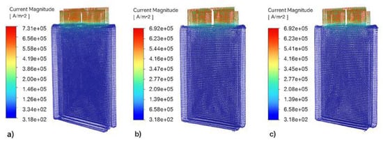
Figure 11.
Current magnitude simulation results for (a) PC+ABS; (b) PEEK; (c) PP.
As a result, PC+ABS exhibited the highest performance in terms of current density and has proven to be a strong candidate for high-discharge-capacity systems. However, this benefit comes with a requirement for more efficient cooling. PEEK and PP, on the other hand, are better suited to systems in which passive or semi-active cooling is dominant because they generate less heat with limited heat conduction. This indicates that the choice of material should depend on both conductivity and thermal management strategy.
In the aluminum reference scenario, an average current density of 7.53 × 10⁴ A m−2 was measured at the battery tab terminals (peak value 7.49 × 10⁵ A m−2), along with a thermal conductivity of 20 W m−1 K−1 and electrical conductivity of ≈3.5 × 10⁷ S m−1. These values reflect the outstanding conduction capability, which is reflected in the electrical conductivity. The metal-flake-containing PC+ABS had almost the same electro-conductivity performance, being only 1.3% lower (7.43 × 10⁴ A m−2) than that of aluminum, and demonstrated almost equivalent electric conductivity. PEEK and PP, on the other hand, exhibited averages which were approx. 6.5–7% lower (≈7.04 × 10⁴ A m−2). With such similarity in current profiles, the battery model NTGK/DCIR was used to keep the net current the same after the voltage adjustment. This was performed for every material. This was necessary because the model performed voltage correction for a constant input power of 190 W for the system, while the current remained the same. Therefore, polymers with low electrical conductivity maintained the same current with a higher voltage drop. On the other hand, the difference in thermal conductivity (~20 W m−1 K−1 against 0.2–0.3 W m−1 K−1) directly affected the temperature field; thus, the polymer cell cores were found to be 15–20 K hotter than the aluminum areas. In conclusion, PC+ABS has a high current-carrying capacity that is maintained with its low mass and processability advantages, while PEEK and PP are limited in their transmission capacity and are secondary in applications that require strong cooling due to increasing thermal loads. The similarity in current density can be explained by the power constant of the system; however, the temperature gradients clearly reveal the decisive effect of thermal conductivity.
4.3. Static Temperature
The static temperature field, one of the most important indicators of the heat distribution in the battery module, was analyzed in each polymer-based composite material, and both the increase in temperature in the central areas and the cooling profile of the end surfaces were studied in detail. In the Fluent simulations, all materials were evaluated with the same geometric structure, heat generation (190 W), and boundary conditions; thus, only the effects of the thermal–physical properties of the material (specific heat, thermal conductivity, and density) on the temperature field were considered. The analysis results (Figure 12) indicate that the lowest average temperature was recorded in the PC+ABS. This material had values of 309.77 K for the negative and 309.77 K for the positive base terminals, identifying it as the best thermal conductor among the battery cells for a general temperature of 310 K. For PEEK, this average value was set at 322.38 K, and for PP, it was 323.96 K. This difference is an indication that PC+ABS dissipates heat more effectively, enabling lower operating temperatures to be maintained under the same heat load.
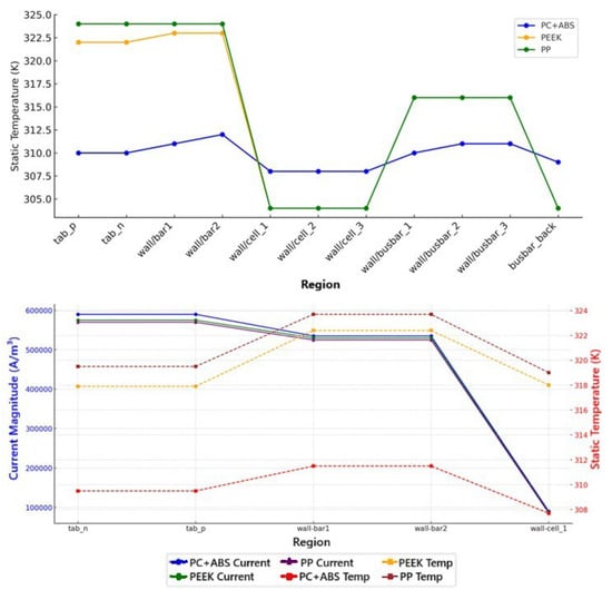
Figure 12.
Static temperature and current magnitude.
The highest local temperature values also had a similar ranking. The maximum temperature for PC+ABS on the tab_n surface was 309.83 K; for PEEK, it was 323.18 K; and for PP, it was 324.91 K. In the regions around the center of the cell body, the temperature deposition in PEEK and PP was distinctly higher than in of PC+ABS. This illustrates the local thermal resistances generated in materials with low thermal conductivity, which prevent heat flow and thus lead to an increase in the central temperature. Indeed, the maximum temperature difference in PP and PEEK was found to be correspondingly higher than in the battery module and can reach up to 15 K.
The minimum temperature values were observed close to the inlet and in the areas where the heat conduction process started; for PC+ABS, it was 309.72 K; for PEEK, it was 320.87 K; and for PP, it was 322.07 K. This difference is not limited to the hot areas of the system, revealing the material’s ability to conduct heat in the system’s regions of ambient temperature. In other words, the PC+ABS composite has more balanced and cooler temperature distribution at not only the local but also the global scale. These temperature data show that PC+ABS, due to its high thermal conductivity, distributes the thermal stress more uniformly and thus enables the battery components to operate in safer temperature ranges. On the other hand, materials with lower conductivity, such as PEEK and PP, cause the temperature to rise, especially in the central parts of the cooler, which results in an increase in thermal risk, mainly due to hot spots. Hence, in cases where the cooling system is passive or the convective effect is limited, PC+ABS appears to be a more advantageous choice in terms of thermal management.
These results demonstrate the absolute dominance of aluminum in thermal performance; however, they also indicate that polymer composites with low density and favorable production processes, together with appropriate cooling strategies, may substitute aluminum in some applications. In particular, PC+ABS can partially control the temperature levels, while PEEK and PP should be considered carefully in cases in which heat management is crucial.
4.4. Total Heat Source
Total heat generation is a highly important parameter for describing a battery system’s thermal capabilities, combining both Joule heating and electrochemical reactions. This study evaluated volumetric heat generation (W/m3) under a constant power load (190 W) for the PC+ABS, PEEK, and PP composites in the base terminals, busbars, and cell bodies. Simulation results showed that the greatest heat generation occurred in PC+ABS, which was 347,790 W/m3 on average in the base terminals, compared to 311,722 W/m3 and 311,708 W/m3 for PEEK and PP, respectively. This increase is due to PC+ABS’s higher capacity for current-carrying and thus Joule heating. Heat production is also affected by current density and local resistivity, with PC+ABS showing a temperature rise of up to 11% due to localized resistance and current concentration. On the other hand, PEEK and PP, with their lower conductivity, produce less heat per unit volume, which makes them more suitable for passive cooling strategies. A similar trend was observed for maximum heat generation, with PC+ABS at 365,418 W/m3, whereas PEEK and PP remained around 327,600 W/m3. An aluminum reference simulation showed significantly lower values—an average of 2.85 × 10⁵ W/m3 and a maximum of 3.25 × 10⁵ W/m3—owing to the metal’s superior electrical and thermal conductivity. PC+ABS generated 22% more total heat than aluminum, while PEEK and PP produced 9–10% more. Despite operating under equal power conditions, higher electrical resistance in the polymers led to greater Joule losses and heat buildup. Therefore, although PC+ABS approaches aluminum’s performance, it requires more effective thermal management. Although PEEK and PP generated less heat, they do not dissipate heat efficiently, which poses a risk in passive cooling applications.
5. Results and Discussion
In this study, during the injection molding process, cooling and deformation data obtained with Moldflow software and thermal performance outputs obtained from ANSYS Fluent were combined to comprehensively evaluate the general suitability of different polymer composite materials for battery module applications. Evaluations were carried out for each material, with systematic assessments of production and thermal management efficiency. Experimental studies in the literature on PC+ABS, PEEK, and PP composites have reported low thermal conductivity values and pronounced differences in dimensional stability. The simulation results obtained in this study are qualitatively consistent with these experimental findings, thereby supporting the reliability of the simulation-based predictions. The large disparity in thermal conductivity between aluminum and polymers does not indicate absolute performance equivalence but rather highlights the specific advantages and limitations of polymer-based alternatives. For instance, while PC+ABS lags behind aluminum in terms of thermal performance, it offers advantages such as lower density and better processability. Therefore, the comparison presented in this study serves not only as a numerical assessment but also as an engineering guideline for material selection. PC+ABS, which is reinforced with metal, can be used in injection molding with less warpage and suitable cooling times due to its short cooling period; its core flow density profile from ANSYS Fluent analyses was found to be very close to that of aluminum. Despite having a thermal conductivity approximately 80 times lower than aluminum, it exhibited effective performance by maintaining temperature distribution in a relatively controlled range (maximum ≈ 310 K). This material is a balanced option, as it offers low density, cost advantages, and ease of production, along with the increase in total heat generation. While PEEK stands out for its high mechanical strength and thermal stability, it showed not only longer cooling times in the Moldflow results but also severe temperature buildup in the central areas during the Fluent analysis (maximum ≈ 322 K) due to its thermal conductivity. This material, with 6–7% lower performance than aluminum in terms of current density, especially in high-voltage systems, still requires careful thermal management. It also requires specific process conditions in terms of temperature control inside the mold during production. PP has the lowest density and the lowest thermal conductivity. In the Fluent analysis, temperature values reached 324 K; this indicates that PP’s heat dissipation capacity is very limited. Moldflow analyses showed that although PP has advantages in terms of production efficiency, with low shrinkage ratios and short cycle times, it lagged behind the other materials in terms of its electrical and thermal performance. Hence, PP-based composites are more suitable for inexpensive, low-density, and limited power applications. The total heat generation results obtained in this study were used as a primary measure for evaluating the thermal management performance of battery modules. However, it is well-established that heat generation consists of two main components: Joule heat (originating from electrical resistance) and reaction heat (arising from electrochemical processes). In this study, these components were not calculated separately; instead, the evaluation was based on the total heat generation. The literature indicates that Joule heat makes the dominant contribution, particularly under high C-rate discharge conditions, while reaction heat plays a more significant role at low current densities. Therefore, the total heat values obtained in this work should be interpreted as trends that predominantly reflect the contribution of Joule heat.
The reference material, aluminum, demonstrated the best performance in all parameters; however, it can only provide a sustainable solution for a limited number of applications due to its high cost, density, and difficulties in shaping. In this context, PC+ABS stands out as the most balanced alternative to replace aluminum; PEEK, on the other hand, can be used in special applications in which cooling measures can be taken if high structural strength is required. PP can be recommended only for designs in which thermal loads are low and the main priority is cost. This comparison of multiple criteria demonstrates that decisions based on a single performance measure are insufficient and that in the selection of the material, the production and operating conditions must be holistically evaluated. This comprehensive comparison is illustrated in Figure 13.
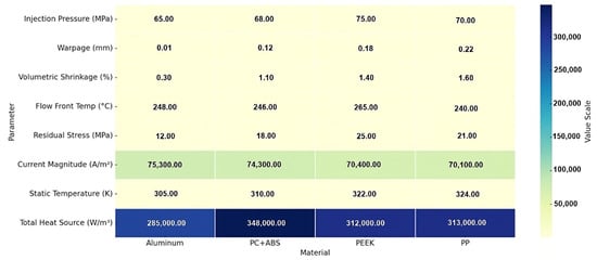
Figure 13.
Multi-parameter comparison of simulation results table.
6. Conclusions
In this study, the production and operating performances of alternative polymer-based composite materials that can be used to replace aluminum in the battery module components of electric vehicles were comprehensively evaluated using Moldflow- and ANSYS Fluent-based numerical simulations. Three different composite materials—metal-containing PC+ABS, carbon-fiber-reinforced PEEK, and mineral-filled PP—were compared in terms of processing properties during injection molding and thermal management efficiency during use. Aluminum was chosen as a reference, and all findings were compared to this reference. The results of the analysis showed that PC+ABS had the most similar results to aluminum in terms of not only production efficiency but also thermal performance. The three selected composite materials (PC+ABS, PEEK, and PP) were evaluated as alternatives to aluminum in battery modules due to their distinct mechanical and thermal properties. This comparison provides a holistic perspective on the advantages and limitations of different engineering polymers. The selection of aluminum as a reference benchmark is meaningful given its widespread industrial use; however, the difference in thermal conductivity does not imply direct equivalence. Rather, it facilitates a clearer assessment of the advantages and constraints of polymer-based alternatives. The microstructural characteristics of materials have a significant impact on their macroscopic performance. In particular, the distribution of filler particles and the orientation of fibers play a decisive role in thermal conductivity, mechanical strength, and dimensional stability. Homogeneous filler distributions can enhance thermal conductivity and reduce temperature gradients, whereas irregular distributions may result in localized stress accumulation and shape distortions. Similarly, the strong alignment of fibers in a specific direction induces anisotropic behavior, which caused the material to exhibit superior performance along certain orientations but reduced performance along others. In this context, Moldflow simulations indicated that low distortion, good temperature management in the mold, and short cycle times were possible, while ANSYS Fluent solutions demonstrated balanced performance with high current-carrying capacities and relatively low temperature rises. While PEEK is a remarkable material due to its high mechanical strength and heat resistance, it also presented some limiting factors as a result of its high production temperature requirement and noticeable temperature accumulation inside the battery module. On the other hand, PP fell short in terms of both thermal and electrical performance, achieving values significantly lower than those of the reference material, despite its low cost and density advantages. Comparative evaluations demonstrated that, in particular, in applications in which the battery base and busbar regions are the most conductive and have the highest thermal conductivity, the composite PC+ABS can be considered as an alternative to aluminum for the conducting material. However, it must be remembered that temperature rises in the central areas of low-thermal-conductivity polymers may cause a performance decrease in passive cooled systems, and additional cooling strategies may be needed to compensate for this. In conclusion, this study confirms that the structural materials applied in battery systems should be evaluated not only in terms of their thermal and mechanical properties but also in terms of production process dynamics. Polymer composites, such as metal-filled PC+ABS, which are used in medium power systems with cost considerations, are sustainable solutions both technically and economically, and they fit perfectly into the green economy. In this study, no new material was developed, nor was a structural design proposed. Instead, three engineering polymers widely used in industry were comparatively evaluated with aluminum in a simulation environment. This comparison systematically revealed the advantages and limitations of the existing materials, thereby providing a foundation for future experimental validation and design optimization studies. The innovative contribution of this work lies in demonstrating the potential application of different engineering polymers in battery modules through a multidisciplinary simulation approach by benchmarking them against aluminum. In this way, the polymers were analyzed not only from mechanical and thermal perspectives but also in terms of their manufacturing behavior, thermal response, and electrical performance, providing a holistic assessment with high engineering applicability. Although direct thermal cycling simulations were not performed, an evaluation of the thermal management performance of the materials was conducted based on their thermal conductivity coefficients and dimensional stability outcomes following injection molding. Since deformation tendencies induced by heat transfer are critical determinants in material selection, this approach offers an indirect yet meaningful indicator of thermal management capability. Accordingly, the term “thermal management performance” is employed here not to denote direct thermal cycling but rather to express material-based comparative suitability. In future works, these evaluations will be supported by thermo-mechanical coupled and time-dependent (transient) thermal analyses. By extending the model with experimental verification data, real battery module performance can be predicted with higher accuracy.
Author Contributions
Methodology, F.T.; Software, A.K.A.; Validation, F.T. and A.K.A.; Investigation, F.T. and A.K.A.; Resources, F.T.; Data curation, A.K.A.; Writing—original draft, F.T.; Writing—review & editing, F.T.; Visualization, A.K.A. All authors have read and agreed to the published version of the manuscript.
Funding
This research received no external funding.
Institutional Review Board Statement
Not applicable.
Informed Consent Statement
Not applicable.
Data Availability Statement
Data are contained within the article.
Conflicts of Interest
The authors declare no conflicts of interest.
Abbreviations
The following abbreviations are used in this manuscript:
| PC+ABS | Polycarbonate/Acrylonitrile Butadiene Styrene |
| PEEK | Polyether Ether Ketone |
| PP | Polypropylene |
| DOE | Design of Experiment |
| FCCCD | Face-Centered Central Composite Design |
| MSMD | Multi-Scale Multi-Domain |
| NTGK/DCIR | Newman–Tiedemann–Gu–Kim/Direct Current Internal Resistance |
| TMS | Thermal management system |
| PCMs | Phase change materials |
References
- Garud, K.S.; Tai, L.D.; Hwang, S.G.; Nguyen, N.H.; Lee, M.Y. A review of advanced cooling strategies for battery thermal management systems in electric vehicles. Symmetry 2023, 15, 1322. [Google Scholar] [CrossRef]
- Tarannum, F.; Danayat, S.; Nayal, A.; Muthaiah, R.; Annam, R.S.; Garg, J. Thermally expanded graphite polyetherimide composite with superior electrical and thermal conductivity. Polym. Adv. Technol. 2022, 1–28. [Google Scholar] [CrossRef]
- Goli, P.; Legedza, S.; Dhar, A.; Salgado, R.; Renteria, J.; Balandin, A.A. Graphene-enhanced hybrid phase change materials for thermal management of Li-ion batteries. J. Power Sources 2014, 248, 37–43. [Google Scholar] [CrossRef]
- Azzopardi, B.; Habib, A.; Kaleg, S.; Onggo, D.; Budiman, A.C. Recent advances in battery pack polymer composites. Energies 2023, 16, 6223. [Google Scholar] [CrossRef]
- Tan, J.; Zhang, Y. Thermal conductive polymer composites: Recent progress and applications. Molecules 2024, 29, 3572. [Google Scholar] [CrossRef]
- Kwon, Y.; Song, Y.S.; Lim, E. Simulation of injection-compression molding for thin and large battery housing. Curr. Appl. Phys. 2018, 18, 1451–1457. [Google Scholar] [CrossRef]
- Baum, M.; Anders, D.; Reinicke, T. Approaches for numerical modeling and simulation of the filling phase in injection molding: A review. Polymers 2023, 15, 4220. [Google Scholar] [CrossRef]
- Khan, M.R.; Swierczynski, M.; Kær, S.K. Towards an ultimate battery thermal management system: A review. Batteries 2017, 3, 9–27. [Google Scholar] [CrossRef]
- Murugan, M.; Elumalai, P.V.; Vijayakumar, K.; Babu, M.; Kumar, K.S. A comprehensive review of thermal management methods and ideal system design for improved electric vehicle battery pack performance and safety. Energy Sci. Eng. 2025, 13, 1011–1036. [Google Scholar] [CrossRef]
- Reghunath, U.; Gudi, A.; Bonala, S. Numerical modeling and simulation to predict thermal runaway propagation in an EV battery pack. SAE Tech. Pap. 2023, 1–759. [Google Scholar] [CrossRef]
- Pejman, R.; Gorman, J.; Najafi, A.R. Multi-physics design of a new battery packaging for electric vehicles utilizing multifunctional composites. Compos. B Eng. 2022, 237, 109810. [Google Scholar] [CrossRef]
- He, J.; Wang, C.; Huang, Y. Thermal management and performance optimization in high-power-density lithium-ion battery modules. Energies 2025, 18, 2294. [Google Scholar] [CrossRef]
- Chiang, K.T.; Chang, F.P. Analysis of shrinkage and warpage in an injection-molded part with a thin shell feature using the response surface methodology. Int. J. Adv. Manuf. Technol. 2007, 35, 468–479. [Google Scholar] [CrossRef]
- Hassan, H.; Régnier, N.; Defaye, G. A 3D study on the effect of gate location on the cooling of polymer by injection molding. Int. J. Heat. Fluid. Flow. 2009, 30, 1218–1229. [Google Scholar] [CrossRef]
- Piccirillo, F.; Scognamiglio, F.; Lasiello, M.; Chiu, W.K.S. Electro-thermal model of a pouch cell battery considering thermal runaway. J. Phys. Conf. Ser. 2025, 2940, 012005. [Google Scholar] [CrossRef]
- Joe, S.; Yoo, K. Study on experimental analysis and simulation model of thermal runaway phenomenon in pouch-type batteries for electric vehicles. JMST Adv. 2025, 7, 143–152. [Google Scholar] [CrossRef]
- Wakale, A.; Ma, S.; Hu, X. A thermal behaviour of battery cell using different electrochemical models (ECM and NTGK). SAE Tech. Pap. 2025, 2025-01-8140. [Google Scholar] [CrossRef]
- Vaidya, R. Thermal expansion of metal-matrix composites. Compos. Sci. Technol. 2015, 50, 13–22. [Google Scholar] [CrossRef]
- Shang, S.; Wang, F. Role of residual thermal stress on the electrochemical performance of a solid-state half-cell. J. Appl. Phys. 2021, 130, 245101. [Google Scholar] [CrossRef]
- Amrit, A.; Bahl, M.; Ranga, S. Multi-objective design optimization of EV battery tray. In Recent Trends in Product Design and Intelligent Manufacturing Systems; Springer: Singapore, 2022; pp. 821–829. [Google Scholar]
- Xu, L.; Wang, S.; Xi, L.; Li, Y.; Gao, J. A review of thermal management and heat transfer of lithium-ion batteries. Energies 2024, 17, 3873. [Google Scholar] [CrossRef]
- dos Anjos, E.G.R.; Marini, J.; Montagna, L.; Montanheiro, T.; Passador, F. Reactive processing of maleic anhydride-grafted ABS and its compatibilizing effect on PC/ABS blends. Polímeros 2020, 30, e2020039. [Google Scholar] [CrossRef]
- Chen, G.; Xu, W.; Zhu, D. Recent Advances in Organic Polymer Thermoelectric Composites. J. Mater. Chem. C 2017, 5, 4350–4360. [Google Scholar] [CrossRef]
- Wang, L.; Niu, J.; Zhao, W.; Li, G.; Zhao, X. Study on Electrochemical and Thermal Characteristics of Lithium-Ion Battery Using the Electrochemical–Thermal Coupled Model. Int. J. Energy Res. 2019, 43, 2086–2107. [Google Scholar] [CrossRef]
- Parmar, M.; Patel, D.; Patel, V.; Patel, R. Thermal simulation of Li-ion battery pack using ANSYS Fluent. In Recent Advances in Mechanical Infrastructure; Springer: Singapore, 2021; pp. 265–274. [Google Scholar]
- Kim, D.; Koh, J.; Choi, E.; Kim, H.K. Cooling performance analysis of battery modules considering the viscoelastic behavior of thermal interface materials. Int. J. Automot. Technol. 2025. [Google Scholar] [CrossRef]
- Yu, Z.; Sun, Z.; Chang, L.; Ma, C.; Li, C.; Li, H.; Luan, C.; Al-Saidi, M.Y.M. Impact of multiple module collectors on the cell current distribution within the battery pack. Batteries 2023, 9, 501. [Google Scholar] [CrossRef]
- Tan, Y.; Li, Y.; Gu, Y.; Liu, W.; Fang, J.; Pan, C. Numerical study on heat generation characteristics of charge and discharge cycle of the lithium-ion battery. Energies 2023, 17, 178. [Google Scholar] [CrossRef]
- Kumar, S.; Mishra, S. Optimization of injection molding process by using different types of conformal cooling channels. Res. J. Eng. Technol. 2022, 13, 47–60. [Google Scholar] [CrossRef]
- Ling, C.; Wang, L.; Kan, C.D.; Yang, C. Thermal-electrical-mechanical coupled finite element models for battery electric vehicle. Machines 2024, 12, 596. [Google Scholar] [CrossRef]
- Lee, Y. A study on the battery case injection molding by CAE analysis. J. Korea Acad.-Ind. Coop. Soc. 2011, 12, 2015–2022. [Google Scholar] [CrossRef]
- Hentati, F.; Hadriche, I.; Neila, M.; Bradai, C. Optimization of the injection molding process for the PC/ABS parts by integrating Taguchi approach and CAE simulation. Int. J. Adv. Manuf. Technol. 2019, 104, 4353–4363. [Google Scholar] [CrossRef]
- Melnyk, L. Influence of mineral filler on the thermal conductivity of polymer composites. Technol. Audit. Prod. Reserves 2024, 6, 6–11. [Google Scholar] [CrossRef]
- Hopmann, C.; Ersch, M.; Haag, J.V. Calculating the thermomechanical behaviour of plastic–metal hybrid components. Materials 2017, 119, 34–39. [Google Scholar] [CrossRef]
- Peyser, P.; Bascom, W.D. Effect of filler and cooling rate on the glass transition of polymers. J. Macromol. Sci. Part. B 2006, 45, 597–610. [Google Scholar] [CrossRef]
- Xuekuan, L.; Zhang, T.; Li, S.; Liu, H. The effect of cooling rate on resistance-welded CF/PEEK joints. J. Mater. Res. Technol. 2021, 12, 53–62. [Google Scholar]
- Kashimatt, V.; Vatnalmath, M.; Auradi, V. A review on conductive polymer composites focusing on advancements in electrical conductivity, and electromagnetic shielding capabilities. Polym. Compos. 2025, 1, 1–31. [Google Scholar]
- Lyubimyy, N.; Pol’shin, A.; Tihonov, A.; Gerasimov, M.; Liyamina, S. Investigation of the efficiency of conformal cooling channels of composite molds. Bull. Belgorod State Technol. Univ. 2022, 7, 101–109. [Google Scholar] [CrossRef]
- Gámez, J.L.; Vilaplana, A.J.; Peydro, M.A.; Selles, M.A.; Caballero, S.S. Predictive ANN modeling and optimization of injection molding parameters to minimize warpage in polypropylene rectangular parts. J. Manuf. Mater. Process. 2025, 9, 236406. [Google Scholar] [CrossRef]
- Siddiqui, V.U.; Jameel, Y.; Halim, M.F.A.; Sapuan, S.M.; Asmawi, N.N.M.; Iqbal, Z. Composites in battery casing and energy storage. Phys. Sci. Rev. 2025, 10, 489–496. [Google Scholar] [CrossRef]
- Madeshwaran, A.; Kumar, G.K.; Suresh, K. Develop a hybrid thermal simulation method for EV motor performance analysis, optim. and select cooling technology. Int. Res. J. Adv. Eng. Hub. 2024, 2, 2643–2651. [Google Scholar] [CrossRef]
- Kulkarni, G.; Mahajan, A.; Maheshwari, A. Comparative material selection of battery pack casing for an electric vehicle. Mater. Today Proc. Int. J. Res. Appl. Sci. Eng. Technol. 2023, 11, 66–75. [Google Scholar] [CrossRef]
- Thirumurugan, M. The influence of graphite filler on the viscoelastic and mechanical characteristics of PC/ABS hybrid composite for automotive applications. J. Mech. Eng. 2024, 21, 143–161. [Google Scholar]
- Osada, T.; Kobayashi, S. Injection molding of metal and carbon composites. J. Jpn. Soc. Powder Powder Metall. 2025, 72, 607–611. [Google Scholar] [CrossRef]
- Guo, Z.; He, J.; Gao, R.; Pan, Y.; Zhang, C.; Fu, J.; Zhao, P. Molding of polyether ether ketone (PEEK) and its composites: A review. J. Zhejiang Univ.-Sci. A Appl. Phys. Eng. 2024, 25, 788–823. [Google Scholar] [CrossRef]
- Wolfsgruber, N.; Tanda, A.; Archodoulaki, V.; Burgstaller, C. Influence of filler type and content on thermal conductivity and mechanical properties of thermoplastic compounds. Polym. Eng. Sci. 2023, 63, 1094–1105. [Google Scholar] [CrossRef]
- Guerreiro, M.; Rompante, J.; Leite, A.C.; Fernandes, L.P.; Santos, R.M.; Paiva, M.C.; Covas, J.A. Development of electrically conductive polymer nanocomposites for the automotive cable industry. Polímeros 2021, 31, e2021021. [Google Scholar] [CrossRef]
- Ranjbaran, Y.S.; Molaeimanesh, G.R.; Shojaeefard, M.H. Thermal performance enhancement of a passive battery thermal management system based on phase change material using cold air passageways for lithium batteries. J. Energy Storage 2023, 68, 107744. [Google Scholar] [CrossRef]
- Li, Y.; Zhou, Z.; Wu, W.T. Three-dimensional thermal modeling of internal shorting process in a 20 Ah lithium-ion polymer battery. Energies 2020, 13, 1013. [Google Scholar] [CrossRef]
- Yu, Y.; Zhang, J.; Zhu, M.; Luyao, Z. Experimental Investigation on the Thermal Management for Lithium-Ion Batteries Based on the Novel Flame Retardant Composite Phase Change Materials. Batteries 2023, 9, 378. [Google Scholar] [CrossRef]
- Ling, Z.; Wang, F.; Fang, X.; Gao, X.; Zhang, Z. A Hybrid Thermal Management System for Lithium-Ion Batteries Combining Phase Change Materials with Forced-Air Cooling. Appl. Energy 2015, 148, 403–409. [Google Scholar] [CrossRef]


Disclaimer/Publisher’s Note: The statements, opinions and data contained in all publications are solely those of the individual author(s) and contributor(s) and not of MDPI and/or the editor(s). MDPI and/or the editor(s) disclaim responsibility for any injury to people or property resulting from any ideas, methods, instructions or products referred to in the content. |
© 2025 by the authors. Licensee MDPI, Basel, Switzerland. This article is an open access article distributed under the terms and conditions of the Creative Commons Attribution (CC BY) license (https://creativecommons.org/licenses/by/4.0/).