1. Introduction
Recently, the eco-friendly nature of wind power energy is being increasingly emphasized. A great deal of effort is being expended to replace fossil fuels and transition to more eco-friendly renewable energy sources to meet goals for carbon-neutrality by 2050. In particular, wind power is an energy source that uses natural forces to produce a great deal of electricity. Wind power energy is generated when the wind hits turbine blades, rotates the turbine, and motors converts its rotatory power into electric energy.
Great efforts are under way to develop large wind turbines around the world. As large wind turbines are more efficient than small ones, the diameter of turbine blades grows, in order to catch more air flow and produce more electricity. However, there is a problem of a rise in transport costs due to the increase in blade length as the wind turbine grows larger. In this paper, a study was performed to separate large blades for transport.
Prior to this study, international and domestic research trends on detachable blades were analyzed. Much research work of segmentation of wind turbine blade has been performed. Mathijs Peeters et al. performed a study on the concept of segmented wind turbine blades. In this review paper, the concept of segmentation of wind turbine blades is summarized [
1]. Alejandra S Escalera Mendoza. et al. conducted study on the design and analysis of a segmented blade for a 50 MW wind turbine rotor. They showed that segmentation of an extreme-scale blade is possible but mass reduction is necessary to improve its feasibility [
2]. Muhammad Basit Ansari et al. performed research on adhesive snap-fit joint for modular wind turbine blades. In that paper, a numerical analysis study on the joint area was performed [
3]. Hongya Lu et al. carried out study on smart segmented blade system for reducing weight of the wind turbine rotor. The design was composed of the segmented blades and a hinged-rods support structure (SBHR) as a means of reducing weight by alleviating the blade moment [
4]. Taesung Kim et al. performed a study on innovative research for a segmented blade method with the pitch control for a large-scale wind turbine structure. In that work, the feasibility of segmentation about blade using the partial pitch method was investigated [
5]. Benjamin Anderson et al. conducted an open-source method for segmented blades. They developed an open source-based blade design system. That study used the open-source design codes WISDEM and OpenFAST, which were applied to wind turbine blade design. The sensitivity of wind turbine design techniques and annual energy production to various parameters was investigated. It was found that stiffness, mass, and position significantly influenced the design techniques [
6]. Eric Ross et al. have conducted research on segmented and pre-aligned blades for very large wind turbine systems. They demonstrated that segmenting the blades would facilitate the fabrication and transportation of large-scale offshore systems. They also suggested that assembly costs could be significantly reduced [
7]. S. Daynes et al. conducted a study on the design and experiment of control surfaces for variable-geometry wind turbine blades. In that work, wind tunnel tests were carried out. The NACA airfoil was adopted [
8]. Jelle Joustra et al. conducted a study on the structural reuse of blades. They applied a segmentation method to this method [
9]. Zhiwen Qin and his colleagues conducted a design study of a 38 m-wide wind turbine blade under extreme loads. They investigated the structural response. A typical commercial wind turbine blade was used. The design involved connection and composites layouts [
10]. Zhiwen Qin et al. designed a multi-bolt-connected composite box beam for a cross-sectional wind turbine blade. They studied the nonlinear response of the structure; it was a multi-bolt-connected box-shaped beam structure [
11]. Baoning Chang et al. performed a study on finite element analysis and design of connection strength of a segmented composite wind turbine blade. Based on a fluid-solid coupling analysis of a 59.5 m full-scale blade, their paper proposed a scarf adhesive/embedded bolt sleeve hybrid connection configuration for a segmented composite blade [
12]. Xavier Lachenal and his colleagues studied the application of wind turbine blades. They reviewed morphing concepts and structural materials. In their study, they applied their research on helicopter blades to wind turbine blades [
13]. Zhiwen Qin and his colleagues conducted a study on determining the split position of a cross-sectional wind power generation system blade. In their study, they investigated the effect of blade split position on the structural performance of the blade [
14]. Faber A. Saldanha et al. conducted a study on a modularization method for wind turbine blades. The blades used were horizontal-axis blades. In that paper, the blade modularization technique and load-carrying performance were evaluated. Their paper presented the development and validation of a novel joint structural system for cross-section blades [
15]. E. Saenz et al. studied a new joining method for blades. They also validated the developed method [
16]. In South Korea, Yonggyu Lee. et al. conducted the development of a 4.3 MW wind turbine blade. In that work, an aerodynamic design study for blade segmentation was conducted [
17]. Various studies have been conducted on large blade transportation and blade segmentation. Large blades are difficult and expensive to transport. Therefore, future research is planned to focus on research into detachable blades. Based on the analysis of previous studies, the design considering the separation location of 5 MW wind turbine blades was performed in this work. In this study, we conducted an optimization on the blade segmentation position. The study on the joint of the separation parts was carried out. In this work, a new technology for selecting segmentation locations is proposed. Furthermore, a new method for connecting segments through bonding is proposed.
2. Aerodynamic Design
The system specification of the blades set in this study was based on the horizontal-axis wind turbine blade design. The design target power was decided to be 5 MW. This is a suitable range for the standard that is being developed at this time. The wind speed was chosen to range from 3 m/s to 25 m/s. This includes the wind condition that is from cut-in to cut-out of wind turbines. The rated wind speed was set as 12.5 m/s, and wind turbines could generate electrical power most efficiently at this speed. In addition, the gust wind condition in extreme situations was considered. It serves as an important criterion for verifying durability and evaluating structural safety of wind turbines in extreme conditions.
The wind turbine was constructed with three blades in total. This is the number of blades used commonly in commercial wind turbines. Blades rotated clockwise, and the rotational speed was set as 23.26 rpm. This speed is a value set for blades to maximize rotatory power and aerodynamic performance as well as produce energy safely.
This study used DU-series airfoils provided by the National Renewable Energy Laboratory (NREL) to improve aerodynamic characteristics of the blade [
18]. These airfoils show excellent performance in low-speed aerodynamic characteristics. Consequently, they are used widely for wind turbine blades. Since the selection of airfoils has a great effect on the blade’s efficiency in addition to lift and drag characteristics, it was determined in accordance with the design goal.
The diameter of the rotor was designed to be 126 m; this size is a diameter used in 5 MW class large wind turbines, which could efficiently absorb high wind energy and convert into electrical power. Determination of the rotor’s diameter contributes to the improvement of the wind turbine’s power by collecting wind energy from a large area. Based on this system specification, aerodynamic design and analysis was performed for the blades.
Table 1 is the design requirement for blades.
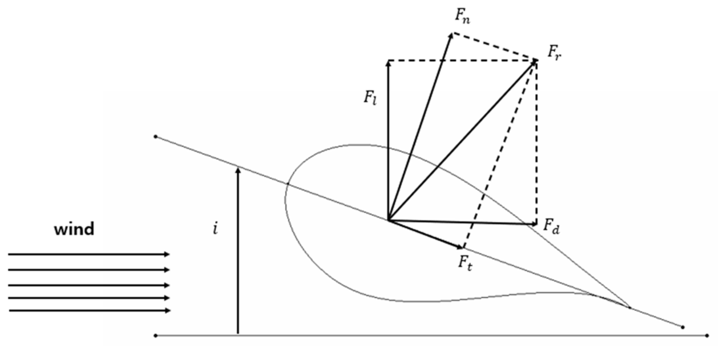
The blade element theory was used to perform the design. In order to find the angle of blade airfoils, this study used the blade element theory. The blade element theory is an effective method for analyzing aerodynamic force applied to the wind turbine blade. It could quantitatively evaluate the change in aerodynamic force by the shape and angle of the airfoil. The aerodynamic force applied to wind turbine blades is primarily composed of lift and drag. The lift is the force generated by movement being relative to wind when the blades are rotating, which acts vertically to the blade’s rotation direction. In contrast, the drag acts in the same direction as the blade’s progress direction, and is generated by the speed of the blades and the resistance of wind.
Figure 1 shows the load applied to blades.
Figure 2 depicts the result of modeling the blade design.
Equation (1) is lift force and Equation (2) is drag force, where is air density. is the area of the blade about each section for design. is velocity of wind.
This study used the lift and drag coefficients, chord length, twisting angle and so on, which are aerodynamic characteristics of blades, to carry out aerodynamic analysis of the designed blade. These factors work as essential variables in evaluating the blade’s performance and deriving the target power. In the aerodynamic analysis process, aerodynamic characteristics of blades were analyzed first to calculate the values of lift and drag coefficients. This contributes to evaluating the lift and drag that blades could generate under specific conditions. In addition, since the chord length and twisting angle of blades have an effect on the blade’s structural safety and aerodynamic efficiency, these factors were considered together to examine whether the target power was derived.
Momentum theory was used to calculate the power of wind turbines by representing the effect of turbine blades on the surrounding fluid as the momentum changes. The wing element momentum theory based on momentum theory is shown in Equation (3). The momentum change in fluid occurs through the wind turbine blade, and it leads to acting torque on the turbine blade in accordance with the principle of action and reaction. Accordingly, the relationship between force and torque for the rotational motion could be expressed as an equation. In blade element momentum theory, the change in blade shape and flow speed is considered to define the speed change factor and the axial speed change factor by rotational speed. The a′ of Equation (5) means axial speed variation factor according to rotational speed. The a of Equation (6) means velocity change factor. These two factors are different depending on the shape and position of blades. It is derived through blade element momentum theory based on momentum theory. S
d represents the ratio that the chord length of blade occupies in the entire circumference. The area which the wind hits and the lift could be used in accordance with the blade volume ratio to calculate the power [
19].
It was verified whether the target power of the result finally designed was derived. As a result of using Equation (7) to find the power with local speed for each section and then verifying whether the target power 5 MW was obtained, 7.56 MW was derived, so considering the generator efficiency of 0.7, 5.08 MW was drawn. Consequently, the performance of the designed wind turbine blade was proved.
To design the blade that could obtain the target power and implement it safely, a process is required that thoroughly examines the power coefficient representing the efficiency of wind turbines. The power coefficient means the energy percentage that turbines could actually extract at the given wind speed, and it is an important measure that evaluates whether the blade designed works efficiently. This allows us to verify whether the blade maintains the performance targeted in the design stage and also has optimum efficiency. In this study, particularly, the power coefficient at the tip speed ratio 7, which was aimed for when designing, was calculated to verify whether the blade properly worked at the best efficiency point. This analysis enabled us to secure the turbine’s reliability and evaluate whether the performance predicted in the design stage was correctly implemented also during actual operation. In the power coefficient calculation process, the blade performance in different wind conditions and operation situations was comprehensively examined to verify whether optimum efficiency was maintained at the targeted TSR 7.
Table 2 shows the power coefficient in accordance with TSR.
3. Structural Design for Segmentation of Wind Turbine Blade
In this study, aerodynamic design was conducted first. The structural design was then performed based on the aerodynamic design results. In this study, a design study on a blade, which is a longitudinally elongated structure similar to a truss structure, was conducted. The structural design was performed by replacing the structure with a long I-beam-shaped structure similar to the shape of a truss structure. After the conceptual design for the structural design, the structural design for segmentation was performed.
Due to the enlargement of the blades, it was designed with two spars that could effectively support the load. This spar flange-web structure plays the role of strengthening the inside of the blade. It was designed to efficiently distribute the force applied to the entire structure by placing respective spar webs at different positions. The thickness, position, angle, etc., of the spar web were designed by optimizing to withstand the load applied to the blades. This allowed us to minimize the deformation of blades and to secure long-term durability [
20,
21]. For structural design, the blade was divided into 13 sections in the longitudinal direction.
Table 3 shows the structural design result for the blade web and skin.
Table 4 shows the structural design results for the spar flange. The material properties for structural design were referenced from existing test results. The specimen test was performed using static material testing system NFEC-2007-10-001003 at Future Mobility Platform Reliability Core Center in Kunsan National University.
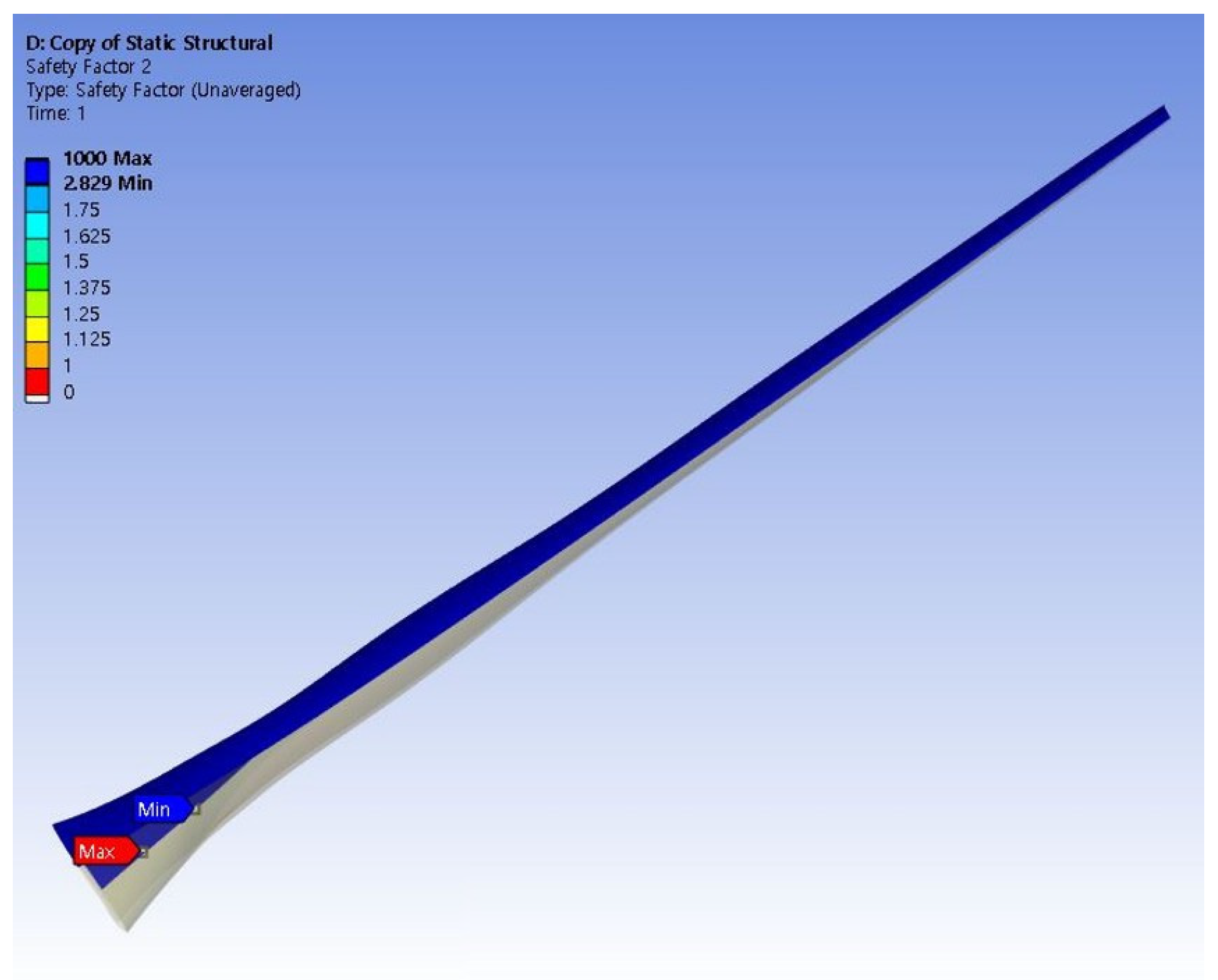
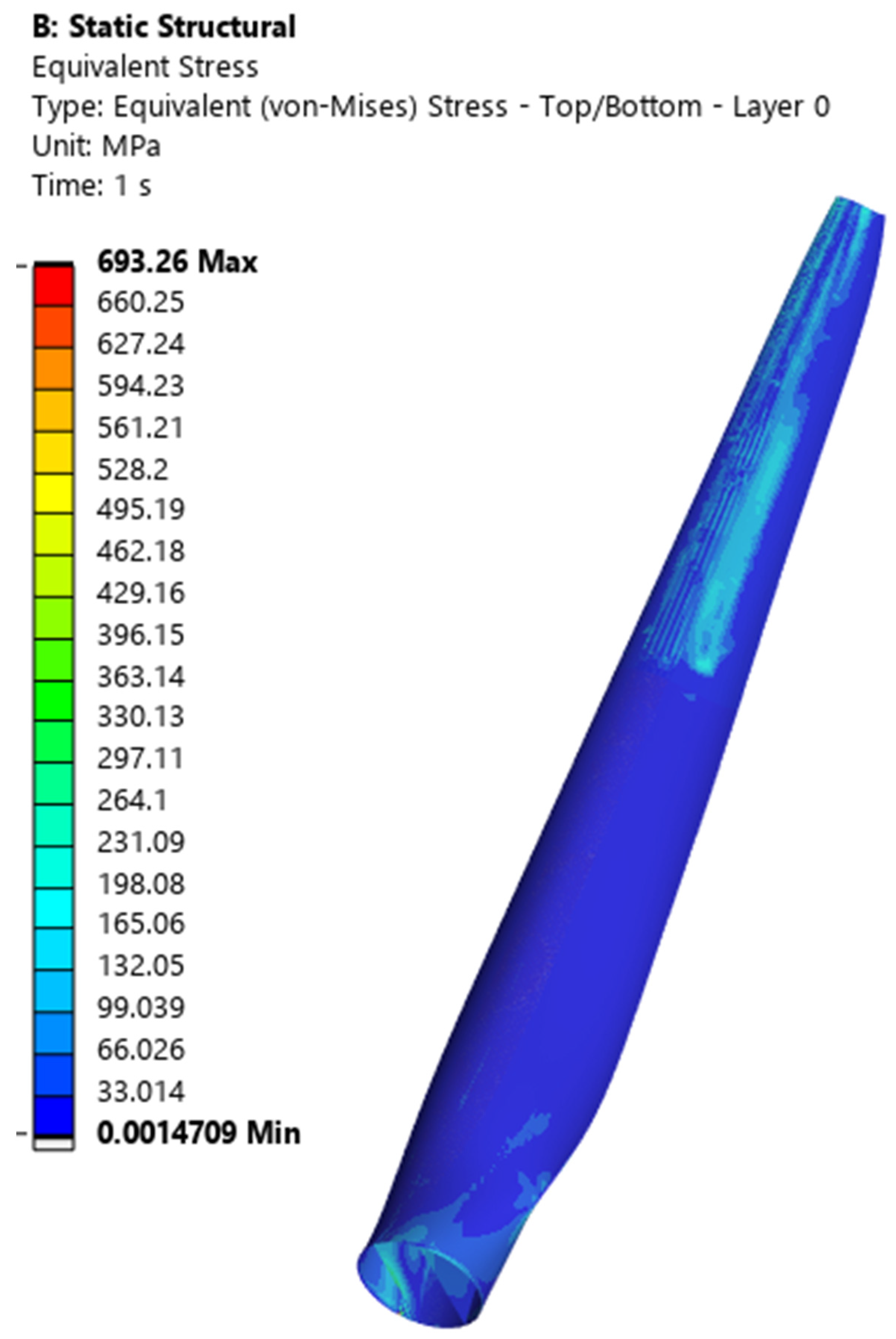
In this study, the analysis was performed with ANSYS 2024, a commercial analysis program, to evaluate the structural safety of blades. Numerical analysis was performed to verify the structural safety of the structural design results. Structural analysis was conducted by comparing stresses against material strength. Furthermore, deformation stability was examined through displacement analysis. The safety of the design results was verified by reviewing the final safety factor. The mathematical model for numerical analysis utilized a finite element analysis model. In particular, for precise analysis considering complex material properties of the composite, which is the main material in the blades, ACP (Ansys Composite Prepost) module of ANSYS was used to reflect the characteristic of composite correctly. This module could model the directionality and stratified structure of composite specifically, so it has an advantage in obtaining the analysis result similar to actual blades. As a result of structural analysis, the safety factor of 2.8 was secured for stress, and the deformation rate was 659 mm, so it was verified enough to be safe.
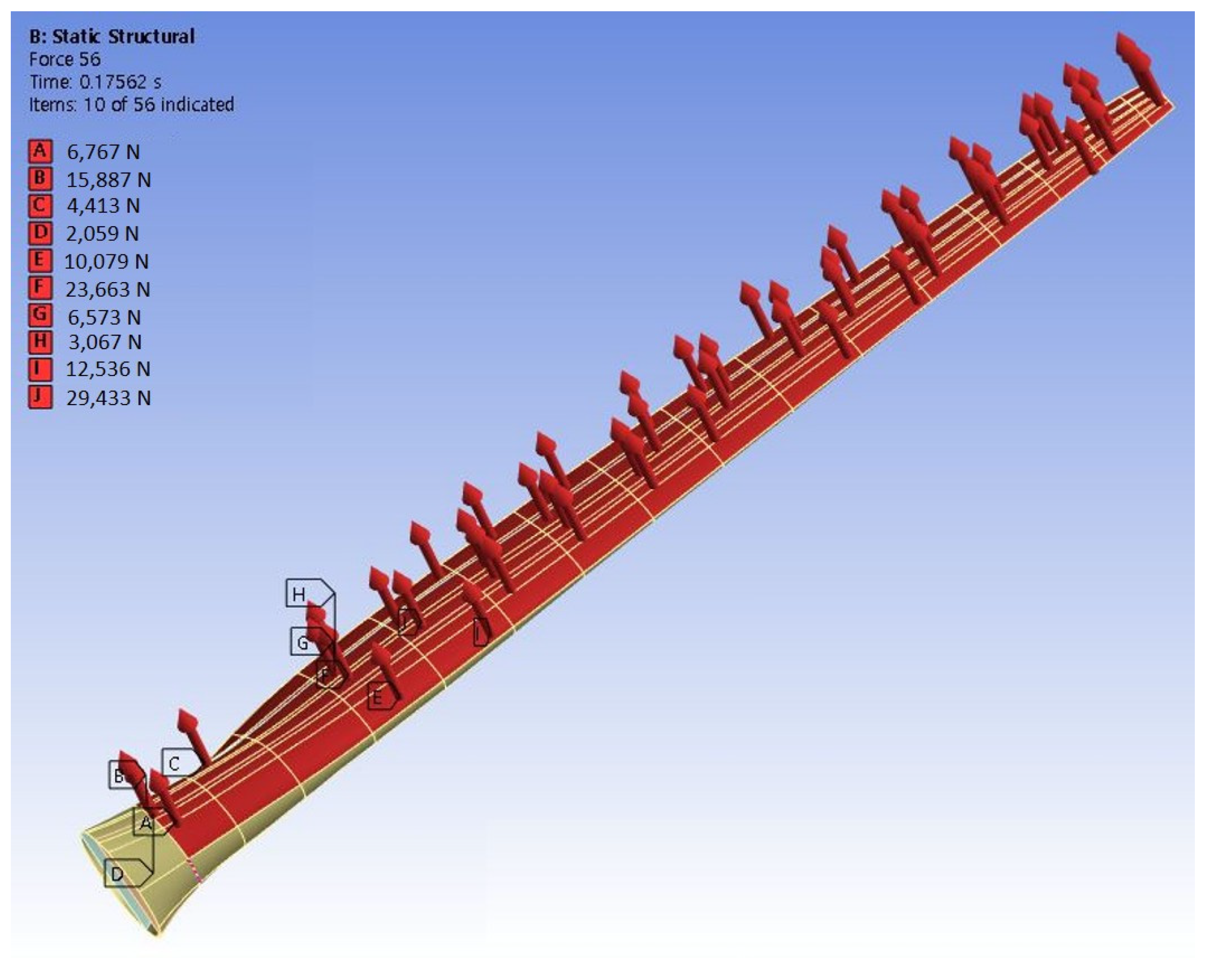
Figure 3 shows distributed load and boundary conditions for structural analysis.
Figure 4 is the safety factor of stress analysis result.
Figure 5 shows the result of stress analysis.
Figure 6 shows the result of deformation analysis.
In this study, after completing the aerodynamic and structural design for blades, various conditions were analyzed to secure the reliability of the blade design and set the optimum segmentation position. In particular, this study started out from the necessity of the segmented blade design considering special environments like mountainous areas in South Korea. Consequently, it was aimed at the design of blades being installable in mountainous areas. The joint part is perfectly combined. The aerodynamic shape remains unchanged. Therefore, aerodynamic performance is not affected.
Since mountainous areas have many restrictions on transport of wind turbine blades due to topographic features, it was a required element of the design that the blades could be transported by segmenting them. Specifically, blades are easier to transport in mountainous areas when their length is 30 m or less. Considering the overall length of 63 m of 5 MW class wind turbine blades, it is needed to segment them into two parts at least. When setting the segmentation position of blades based on such a condition, the conclusion was reached that segmenting at the middle point of the blades has a higher structural efficiency than segmenting the front and rear part of the blades. This is because the restrictions occurring during transport and assembly could be reduced in addition to maintaining structural strength if segmenting at the middle point of the blades. This design is favorable to load balancing and load distribution of the overall blade, so safe installation is possible.
If segmenting blades to transport, the increase in the device’s load for joining the segments should be considered. The farther from the blade root, the more the load tends to increase. It is paticularly not appropriate to set the segmentation position closer toward the tip. Since the tip part is a section that has lower structural strength and receives relatively higher stress, it could be disadvantageous for maintaining the strength and safety of blades when segmenting. As a result of this analysis, it was determined that the point between 40% and 60% of the overall length is the position suitable for segmentation for 5 MW class wind turbine blades. Segmenting at this position not only efficiently distributes the blade’s load but also makes installation and transport easy. Consequently, it enables designing a blade that could be efficiently installed even in mountainous areas. Considering the safety of the joint at the separation location and the optimization method for transportation, the 50% location was considered the most appropriate. To achieve weight reduction, a size optimization technique was applied to the design of the bonding area. The design variables of the bonding area were mainly the shape of the blade skin, spar cap, and the bonded part. The joint of the segmented blades responds to various temperatures/environments (low temperature, shock, vibration, and humidity). In this study, materials applicable to the aerospace field were used. The adhesive used was 3MEC-2216B/A, which has been certified for durability. The bolt connection used M30 bolts made of Ti-6Al-4V.
First, the load of the joint was analyzed at different segmentation positions and the change in the load applied to the blade structure. In this process, structural analysis was used to quantitatively evaluate the effect of the joint load on the blade. In particular, the stress concentration and strain occurred by adding the joint load were analyzed. It was also analyzed how the blade reacts under normal operation and extreme conditions. Based on these load and stress analysis results, the structural safety of blades was evaluated depending on the segmentation position and the optimum segmentation position was selected.
Optimum segmentation position should not only have a minimum effect on the blade’s performance but also make installation and maintenance easy. In addition, it should be able to assure the structural reliability of blades at the same time. Ultimately, the blade’s overall performance could be improved, and structural safety could be secured by optimizing the segmentation position.
This study considered the design of joints at respective segmentation points to analyze the segmentation positions of the blade. After determining the position of joints, the effect of resultant load increase and load condition change on blade’s safety were evaluated.
In particular, the safety coefficient was examined to analyze the effect of weight increase caused by joint installation on the blade’s structural safety. As a result, it was decided whether safety is maintained if segmenting blades, and the result required for determining optimum segmentation positions was drawn. The purpose of this study is for the design of segmented blades to maintain safety under actual load conditions.
The safety coefficient for joints was designed to be 2.3 or more. The design for joints was aimed at installing at the space between the leading edge and middle spar web. For the joint part, safety was increased by securing the contact surface as much as possible considering the connection between bolts. Since additional load occurred due to the joints, it was designed to keep a minimum load and not to significantly affect the blade’s safety coefficient by optimizing them. For the final blade, the design was optimized by segmenting the blade at the 50% point.
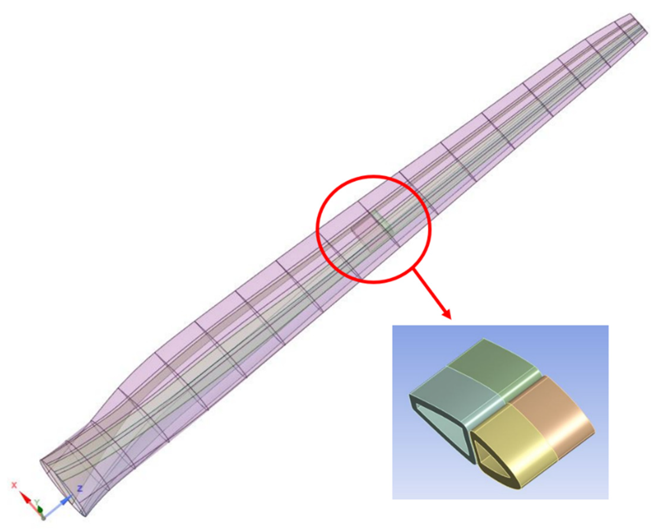
Figure 7 is the result of modeling for the joint.
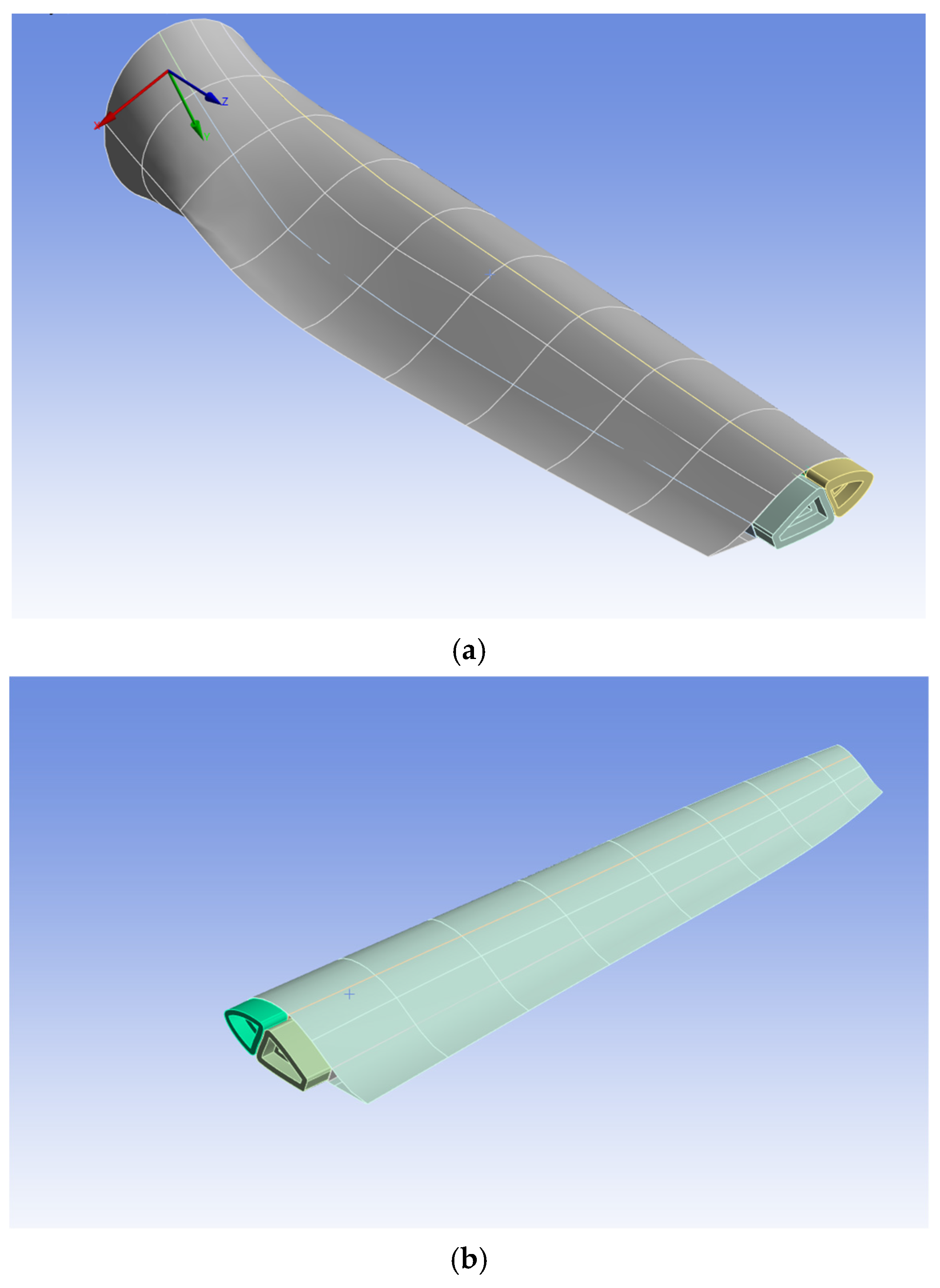
Figure 8 is the configuration of root part for blade joint.
Each blade’s joint was designed to be 1 m in length and 15 cm in thickness. Basic steel properties were applied to materials. Joints between the leading edge and two spar webs were joined by adhesion. In the structural analysis process, the jointed boundary condition was applied to the blade segmentation part. The jointed condition was given to the joint part, and the safety coefficient was examined to determine whether the blade was able to be used safely while operating.
The safety factor for the blade’s joint part was 2.39, which was determined to be safe. Therefore, it was confirmed that the joint had connected blades safe enough in operation. The mass of blades was calculated as 46,225 kg. Consequently, it was observed that blades were safely operating even if the load of joints was added.
Figure 9 shows the safety factor of the joint part.
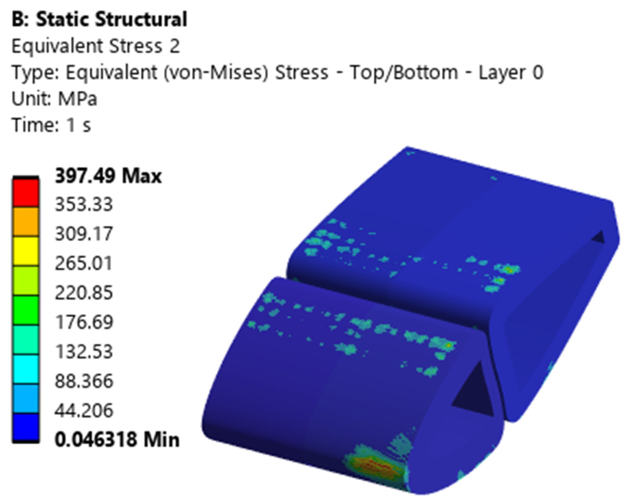
Figure 10 shows a stress analysis result of the joint part. The joint safety factor in this study was derived based on a self-load scenario and was confirmed to exceed the safety factor (1.35–1.5) for the ultimate load conditions suggested by DNV-ST-0376 and IEC 61400-1. However, since the design load and fatigue test conditions specified in the industry standards were not fully reflected, future research will need to be conducted based on these standards.
4. Conclusions
In this study, 5 MW class large wind turbine blades were designed and analyzed considering the transportation of large wind turbine blades. The wind turbine blade designed was segmented at the specific segmentation point, and the joint was installed at the same time. The performance of the design result was proved by analyzing the safety coefficient for the load increase due to installing joints and corresponding load change.
In this study, the blade designed using DU-series airfoil provided by NREL was 63 m in radius, 61.5 m in diameter, and 13.26 rpm in rotational speed. The tip speed ratio (TSR) was 7, which was designed for large wind turbine blades. For the blade’s angle of attack, the maximum lift and drag of airfoil was considered. The final optimum angle was determined. The power, torque, and power coefficient were analyzed using the lift and drag caused by the angle of airfoil. Based on them, reliability for the design was secured. Structural design was carried out based on the aerodynamic design result. The structural shape was designed with the structure form of two spar flanges and webs. In addition, the spar was designed with a foam sandwich structure shape. The skin was designed after designing the spar. Carbon fiber composite and glass fiber composite were applied for the composite. In order to select the segmentation position using the blade designed, Daegwallyeong Wind Farm, which is an onshore wind farm in South Korea, was considered. Referring to the length of the wind turbine blade that could be transported in mountainous areas, the number of segmentations for the wind turbine blade was determined. Finally, a longitudinal 50% point of blade was determined as the segmentation position. Segmentation was carried out at the 50% point of blade, and the joint was designed for the blade segmentation. Structural analysis was performed considering the increased load caused by mounting the joint. The safety of blades was confirmed through the final structural analysis.
A limitation of the numerical analysis results of this study is that fluid–structure interaction analysis was not considered. The structural load was calculated by analyzing the results of the aerodynamic load calculation. We plan to improve this area in the future. We plan to further deepen our research on fluid–structure interaction analysis to complement our findings. This study did not investigate the vibration and fatigue characteristics of segmentation. We will conduct further research on this in the future.
