Abstract
This paper presents the design process of a composite wheel rim for a Formula Student race car. First, the design requirements for composite rims are outlined, which are driven to ensure safe operation as well as compliance with race regulations. Next, a novel methodology for the iterative design of composite wheel rims is proposed, and its steps are individually presented. The load cases were determined using data from lap time simulations and from practical experience from the operation of previous race cars. Material cards for the simulations were created by measuring the characteristics of the prepreg composites. The geometry of the rims was created by prioritizing the optimum contact with the tires. After creating the rim geometry, the composite material cards, and the simulation’s pre-processing, the layup iteration process began. In this manual iterative process, FEM simulations were run and their results were evaluated. The desired component properties were reached after 11 layup iterations. The final result is a weight reduction of 35% compared to the aluminum rims and 15% compared to the previous multi-piece CFRP rims, without a compromise in operational safety. The main novelty of the paper is the description of the iterative layup selection logic and process in detail, as well as demonstrating this on a concrete use case.
1. Introduction
In race vehicle design, weight is a critical factor for enhancing performance. This is especially true for the unsprung mass as well as the rotating components of the suspension. Although race vehicle wheel rims are typically made of lightweight metals, several attempts have been made in the past decade to develop carbon-fiber reinforced polymer (CFRP) alternatives for these. In comparison to “classical”, non-rotating CFRP-based components, the challenge here is firstly to design a component able to withstand the loading specific to rotating wheels, i.e., the transfer of significant torque between the wheel hub and the tire, dynamically varying lateral, longitudinal, and vertical loading due to the excessive braking, acceleration, and cornering during a lap, the tire pressure acting on the perimeter of the rims, as well as elevated temperatures due to the vicinity of the brake disks. Another major challenge is to follow an efficient iterative design process in selecting the optimum layout of the CFRP layers. This is a crucial element of the design, since the lack of a logical sequence of iterations can lead to a lengthy design process yet result in a non-optimal overweight product. Despite this, the literature generally lacks a proper description of the design process itself.
Table 1 provides an overview of the state-of-the-art in the field of CFRP-based wheel rim design, highlighting the aspects of the employed design process itself.

Table 1.
Overview of the state-of-the-art on the design of CFRP-based wheel rims for race vehicles.
As can be seen, most papers rely on manual iterations during the design process, but they typically lack detailed explanations of the iteration method or the number of iterations performed. Only a few studies [2,7,8,14] employ algorithm-based optimization techniques. While these studies provide information about the iteration numbers and describe the algorithms used, they often neglect critical aspects of the design, such as the practical issues of component design and manufacturing. For instance, some approaches involve non-integer fiber orientation angles, which are impractical for real-world applications [2]. Additionally, algorithm-based methods appear to be significantly more resource-intensive in comparison to manual iterations, with reported iteration counts ranging from 35 to 60 [2,7,8,14], in contrast to just 11 iterations in the case of a manual method [11]. Moreover, these works rarely include comprehensive details on the computational costs.
The logic behind layup iterations is explicitly addressed in only a small number of papers, and even these fail to explain the rationale behind selecting the initial layup or the approach to modifying the layup between iterations [7,14]. Furthermore, no prior work has utilized loads derived from multibody simulation-based lap time simulations, a potential oversight that may have resulted in suboptimal final layups. Finally, only a limited number of studies incorporate material data that has been experimentally verified, further limiting the reliability of their findings.
Several papers [15,16,17,18] address the possibility and the applicability of using machine learning or artificial intelligence to develop composite components, but only a few [17,18] describe the logical process behind their method. Neither of these papers incorporates material data gathering and verification, limiting the reliability of their findings as well. Also, it must be noted that artificial intelligence is conceptually distinct from the algorithmic methods considered here, as it operates on data-driven learning rather than engineering-based logic.
Although dozens of papers, examples [19,20,21,22], deal with FEM simulation of composite structures, they do not deal with how they obtained their used composite layup structures.
To address these gaps, this paper aims to accomplish the following:
- Determine the loads acting on the structure using multibody lap time simulation methods;
- Provide a detailed description of the layup iteration method, emphasizing the selection of the initial layup and the logic behind layup modifications;
- Utilize experimentally obtained material data to create accurate material cards;
- Evaluate the cost of the complete manual optimization simulation process;
- Critically compare the manual iteration method with algorithm-based approaches in the literature, focusing on resource requirements and practicality.
In summary, this paper aims to offer, for the first time, a comprehensive and novel approach to composite layup optimization by presenting a fully described manual iteration method, addressing critical gaps in the existing body of work.
The test case, the aim of which is to demonstrate the novel design methodology, is the 10-inch wheel rim of the Formula Student race car of Arrabona Racing Team (ART) at Széchenyi István University. The initial model modifies the geometry of a commercial aluminum rim designed as a two-piece structure. The primary objective of the redesign is to optimize weight while maintaining structural integrity, performance, and compatibility.
2. Formula Student Wheels
Formula Student is a racing category in which teams of university students design, manufacture, and race an open-wheel racecar with an electric motor or combustion engine-based drivetrain.
Many teams prefer to purchase wheels from commercial manufacturers, who offer one-piece wheels in aluminum, magnesium, or CFRP, while others provide multi-piece designs that allow for customization [23].
Multi-piece wheels blend commercial aluminum rims with custom centers, often machined or 3D printed. CFRP rims have grown popular for their significant weight reduction compared to aluminum while needing simpler, less expensive tooling.
Custom CFRP wheels offer high customizability and stiffness, along with considerable weight savings. However, they come with high material and production costs, requiring specialized composite knowledge and tools, making them more challenging for teams to produce effectively.
The ART, on whose vehicle’s wheel this paper will demonstrate the proposed design process, previously used 2-piece rims with a custom center, which were replaced with in-house designed CFRP rims with metal 3D centers (Figure 1 and Ref. [24]). After the wheel width changed from 7.25″ to 8″ for better contact patch utilization, the CFRP rims had to change as well. Since the costs of the lamination tools for a multi-piece wheel are quite similar to a single-piece wheel, while offering further weight savings, the decision was made to design new CFRP rims.
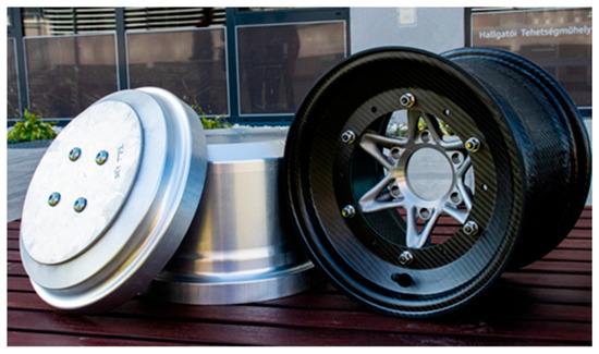
Figure 1.
ART’s previously used a three-piece CFRP rim and its laminating tools.
3. Design Requirements
The redesigned wheels must meet several critical criteria to ensure both safety and performance. They must support failsafe operation with a minimum safety factor of 1.2, and global displacement must remain below 3.0 mm. Compatibility with the car’s current suspension geometry and wheel hub design is essential, allowing for easy interchangeability with existing CFRP and aluminum wheels.
Reducing weight is a primary goal, with the target of lowering the wheel rim’s weight to less than 1000 g, which represents a 35% reduction over aluminum rims and 10% over two-piece CFRP rims. Feasibility of production by ART and its partners, along with cost-effectiveness, is another priority, balancing performance gains with budget considerations.
4. Methodology
In this paper, an iterative design methodology is proposed to be used. The iterative design methodology requires a cyclic process, which is illustrated in Figure 2. The process is composed of four main phases: (1) virtual prototyping, in which the geometry of the rim, the initial layout, and the loads are determined; (2) the FEM analysis of the wheel rim, the results of which are evaluated on the basis of whether the requirements on failure criterion, stress distribution, and displacement have been met; (3) the iterative modification of the layout for the case that the criterion in Step 2 have not been met. This third step employs 3 different logical decisions and corresponding layup modifications, depending on which criterion has not been satisfied. This iterative process is repeated until all criteria are simultaneously satisfied. A key novelty of the process is the clear definition of the layup modification logic, i.e., adding or removing twill layers or adding unidirectional (UD) layers, until the final, optimum layup is reached.
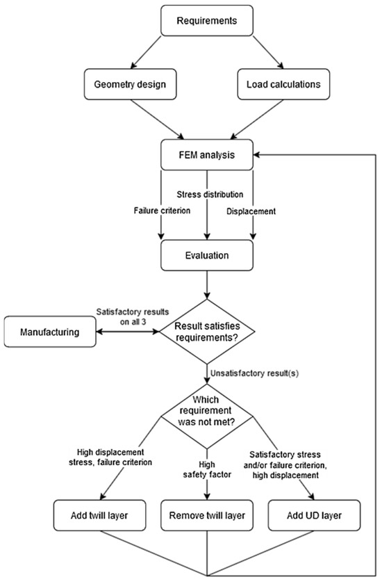
Figure 2.
Iterative design methodology flowchart.
5. Load Case Determination
To design and simulate the structural integrity of the new wheels, it is critical to accurately define the forces they experience under various conditions. For this purpose, the IPG CarMaker 13.0.1. lap time simulation software was employed. IPG CarMaker enables precise modeling and simulation of vehicle behavior via Multi-Body Dynamics (MBD) simulations by replicating real-world scenarios in a virtual environment. It allows users to evaluate the performance of various components (including the wheels) under controlled conditions that mirror real-life situations.
In this study, the software was used to estimate the forces acting on the contact patch of the wheels during different driving scenarios, such as acceleration, braking, and cornering. To ensure the highest degree of accuracy, the car model was developed to replicate the exact specifications of the vehicle, including its suspension geometry, weight distribution, and drivetrain configuration. Similarly, the track environment was modeled to reflect the physical characteristics of the surfaces on which the vehicle would be tested, including factors such as curvature and grip levels. The software’s advanced algorithms calculated the forces generated at the tire-road interface, including vertical, lateral, and longitudinal forces.
The first simulation scenario aimed to define the maximum longitudinal forces acting on the wheels for the latest race vehicle of the ART, codenamed ART_11. This simulation involved accelerating the car to its maximum speed and then braking fully on high-grip tarmac. The second simulation scenario was focused on lateral forces, using a 30-meter-diameter skidpad to simulate maximum lateral loads. In the third simulation, the Formula Student Germany autocross track was used under ideal conditions to examine combined longitudinal and lateral forces on the wheels, providing a comprehensive view of simultaneous force impacts. The loads resulting from these scenarios are summarized in Table 2.

Table 2.
The forces acting on the contact patch of the wheels for the ART_11 race vehicle.
For validation, live data from a previous vehicle of the ART, codenamed the ART_09’s onboard telemetry, recorded during the 2022 Formula Student Germany (FSG) competition, was used. In IPG Carmaker, the ART_09 model, modeled with the same principles as ART_11’s model, was simulated, allowing a comparison of maximum longitudinal and lateral acceleration values with those recorded in actual competition. As shown in Table 3, the simulation results closely matched the telemetry data, with only minor differences. These discrepancies likely result from IPG Carmaker’s virtual track setup, which allows slight corner-cutting by the virtual driver, unlike the actual FSG racetrack, which uses cones that prevent corner-cutting.

Table 3.
Comparison between simulated and recorded peak acceleration values (in terms of gravitational acceleration, i.e., G’s) for the ART_09 vehicle to enable validation of the simulation environment.
Since specific torque figures for ART’s engine were not available, a torque estimate of 1000 Nm was chosen. This included all gear ratios in the car’s drivetrain and a safety factor. This approach ensures that the new rims will be compatible with potential future upgrades, such as a switch to turbocharged engines or electric hub motors, both of which may exert higher torque than the current internal combustion engine.
Another load experienced by the rims is the tire pressure. A pressure of 4 bar was set on the rim’s surface, reflecting the pressure exerted during tire mounting, as this is the maximum pressure needed to slide the tire onto the rim. When inflated, the tire’s sidewall stretches the bead under this pressure, but since simulating the entire tire was beyond the scope of this paper, this effect was not simulated.
Thermal loads were also essential to consider, as heat exposure can impact the material’s mechanical properties. This is especially critical for composite parts, where elevated temperatures can compromise the integrity of the epoxy resin. Previous tests using thermal indicators (Figure 3) showed that, while brake disks may reach temperatures exceeding 400 °C, the inner surface of the wheels has never surpassed 50 °C. Based on these observations, using CFRP components in this area is considered safe, and it is not necessary to include the heat load in the simulations [24].
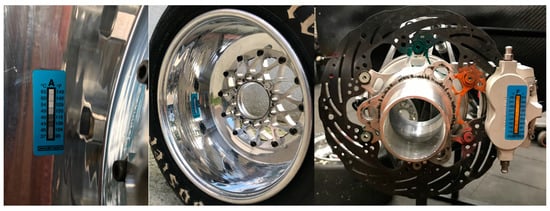
Figure 3.
Temperature measurement devices on the rim and front suspension.
Overall, the validated IPG Carmaker simulations, the estimated torque values, the pressure values, and the validated thermal data provide a reliable foundation for load parameters in designing the ART 11’s new CFRP wheel rims.
6. Geometry Design
For time and cost efficiency, the new CFRP rims use the same geometry for both the front and rear axles. While most dimensions match the previously used rims, the width has been increased from 7.25″ to 8″ based on ART‘s suspension geometry subgroup’s recommendation to improve tire contact. The design (Figure 4) follows the European Tyre and Rim Technical Organisation’s (ETRTO) standards, which provide guidelines for street-use rims, ensuring secure tire mounting and stress reduction during changes. Though race car rims do not require strict adherence to road vehicle regulations, these dimensions serve as valuable references for rim sizing and bead seat alignment.
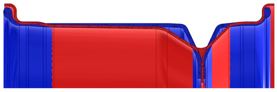
Figure 4.
Comparison between the commercially available aluminum (blue) and the custom-designed CFRP (red) rim geometry.
Finally, CAD (Autodesk Inventor 2025.3) clearance checks confirm a minimum 3 mm gap between the rims and nearby suspension components. With a maximum rim deflection of 2.7 mm anticipated at the rim edge, this clearance prevents interference and maintains structural integrity.
7. Material Tests
This section details the preparations required for the finite element method (FEM) simulation for the wheels. One of the main challenges in this process was addressing the orthotropic behavior of fiber-reinforced composites, which required specialized consideration of fiber orientation, resin properties, and structural demands. To achieve these objectives, the design process involved close collaboration with the Chassis department of ART, the subgroup responsible for the design and manufacture of the composite sandwich-structured monocoque.
Material property determination was a critical stage due to the inherent variability in textile composites, where material properties depend on fiber type, matrix material, fiber-to-matrix ratio, and the production process itself. While manufacturer data sheets for the carbon fabrics are available, these provide only partial information. Therefore, experimental testing was necessary to define specific material properties. This required testing specimens [Figure 5] prepared from the carbon fabrics used in the wheel’s design, specifically the 2 × 2 twill woven prepreg and the unidirectional (UD) fiber fabric.
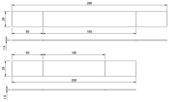
Figure 5.
Unidirectional (above) and twill (below) tensile test specimens.
The production of testing specimens followed a standardized process to ensure consistency and accuracy. Testing (Figure 6) was conducted according to ASTM D 3039 [22] and D 3818/D 3518M [25] standards, due to the availability of the necessary testing equipment and the familiarity with these standards. The tensile tests for twill fabric assessed properties along its main axis, while UD specimens were evaluated in both the fiber and transverse directions. Additionally, shear tests, conducted with a rotated fiber alignment, analyzed the shear force between fibers under tension. While compression tests were planned, they were ultimately omitted due to the associated costs. Instead, values were estimated based on data sheets and measurements from similar materials [26].
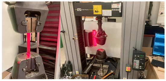
Figure 6.
Tensile testing machine with the specimen. The tests were conducted at 2 mm/min and at a constant 20 °C room temperature.
The test results yielded detailed data to characterize both the twill and unidirectional (UD) fabrics, establishing the foundation for FEM modeling. Based on these results, material cards (Table 4 and Table 5) were created, which include key orthotropic properties essential for realistic simulations. E1 and E2 denote the Young’s moduli along and transverse to the fiber direction, defining stiffness in the principal material directions, while G12, G13, and G23 represent the shear moduli, quantifying the material’s resistance to in-plane and out-of-plane shearing. The Poisson’s ratio (ν12) captures the transverse strain arising from longitudinal loading. Strength parameters include the tensile and compressive limits along and transverse to the fibers (S1T, S2T, S1C, S2C) and the in-plane shear strength (Sshear), all critical for predicting failure under complex loading. Finally, represents the material density, necessary for accurate mass and inertia calculations. These material cards were essential for simulating real-world stress distributions and refining the structural design of the CFRP wheels, ensuring they are both lightweight and durable.

Table 4.
Twill prepreg carbon fiber material card [26].

Table 5.
UD prepreg carbon fiber material card [26].
8. FEM Simulation
8.1. Pre-Processing
In the first step, the CAD model was imported into ANSA v23.1.2 pre-processing software, where irrelevant details were simplified and data conversion errors were corrected to ensure connected elements. The rim model was simplified by using a 1/6th CAD section, meshed with first-order shell elements at the mid-surface (Figure 7). Initial element size trials (4 mm, 2 mm, and 1 mm) indicated that a 2 mm size worked well, but further refinement was needed at the rim’s center part, ultimately using a uniform 1 mm mesh. The wheel center, a secondary component, was modeled with 2 mm tetra elements to balance accuracy with a reduced element count.
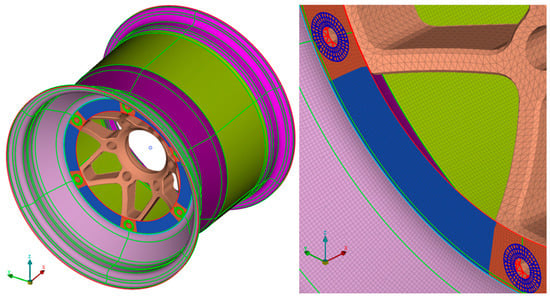
Figure 7.
The meshed rim and center (left) with their constrained contact (right).
Boundary conditions were set by defining loads and constraints. The rim and wheel center were joined by constraints simulating bolt connections, maintaining stability without relative movement. The forces of the contact patch were modeled by applying the forces on a node placed in the theoretical center of the contact patch and linking it to the rim with distributed coupling constraints (Figure 8, left). Abaqus 6.13 was used for the FEM simulations and has a pressure load option preset; it was applied across the internal faces of the rim during the simulation. The torque is applied to the wheel centers via couplings from a single load (Figure 8, right), modeling real-life conditions. Primary constraints fixed the wheel center’s connection to the theoretical wheel hub, while for the torque load case, the node representing the contact patch was constrained.
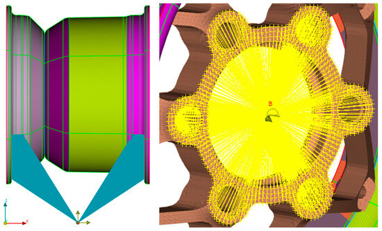
Figure 8.
The loads from the contact patch (left) and torque (right) defined on the wheel. Point B is the center point of the wheel were the torque load is applied.
8.2. Layup Iteration
The start of the layup iteration was a symmetrical alternating layup of 10 layers of twill at 0° and 10 layers of twill at 45°. It was selected as an easily modifiable base that guarantees that the iteration starts with an upward trajectory (in stress and failure criterion).
The iteration method is based on the flowchart shown in Figure 2, with a goal of 3.00 mm displacement and Tsai–Wu failure criterion (TSAIW) of 0.833. Iteration results for multiple parameters throughout the design are shown in Figure 9, Figure 10, Figure 11, Figure 12, Figure 13, Figure 14, Figure 15 and Figure 16, showing a clear trend towards the expected final results. Note that from iteration 5 to 6, a great jump in the results can be seen due to modification of the layer sequence in multiple layer zones (Table 6).
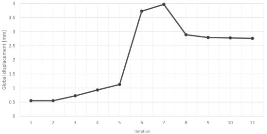
Figure 9.
Change in maximum global displacement (U) through the iteration process.
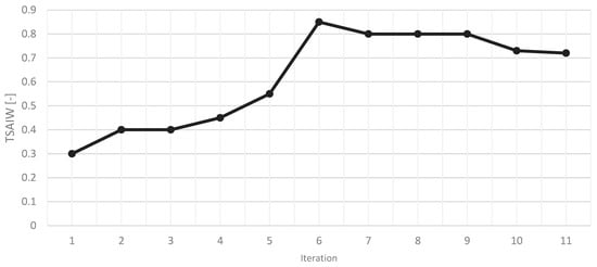
Figure 10.
Change in the maximal value of the Tsai–Wu failure criterion (TSAIW) through the iteration process.
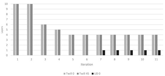
Figure 11.
The change in the layering sequence of the “Rim outer” zone through the iteration process.
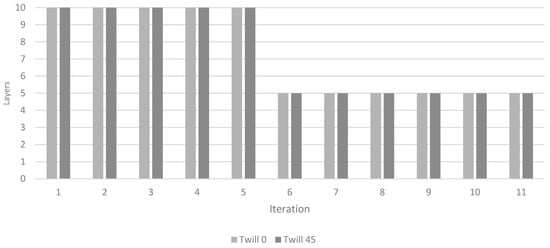
Figure 12.
The change in the layering sequence of the “Rim center1” zone through the iteration process.
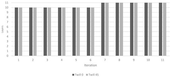
Figure 13.
The change in the layering sequence of the “Rim center2” zone through the iteration process.
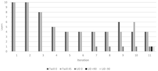
Figure 14.
The change in the layering sequence of the “Rim inner1” zone through the iteration process.
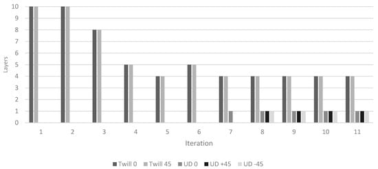
Figure 15.
The change in the layering sequence of the “Rim inner2” zone through the iteration process.
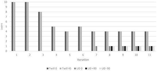
Figure 16.
The change in the layering sequence of the “Rim inner3” zone through the iteration process.

Table 6.
The layer zones of the rim.
Composite layer performance was analyzed with the Tsai–Wu failure criterion, aiming for a failure factor below 0.833. Peak stress areas on the rim reached 1.015 (see Figure 17), a common fringe effect at element edges, disregarded in final assessments. The rim’s global displacement under combined loads was 2.763 mm, within the 3 mm limit, with critical suspension points positioned well inside the rim’s displacement zone. For the torque load, the maximum failure factor was 0.796 with a similar distribution along the rim.
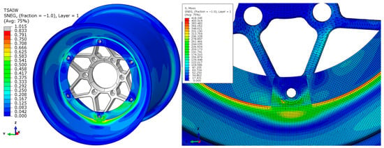
Figure 17.
Stress distribution on the rim with the final layup iteration.
9. Final Layup
From previous project insights and simulations, optimized layer structures for the six rim sections were developed, combining twill and UD materials to leverage each material’s strengths. Symmetry was a primary design consideration to handle complex loads like braking or cornering while accelerating. The ply sequence was also arranged to integrate the rim-bead seat contact areas structurally within the midsection. Overlaps were added to maintain fiber continuity, enhancing durability. Table 7 details the final layup for each rim section.

Table 7.
Final plybook for each rim section.
Finally, the weight of the component was evaluated, which result is shown in Table 8. Based on prepreg data and ART’s past composite manufacturing experiences, the final wheel’s mass was calculated to be about 850 g, a 35% reduction from aluminum rims and 15% lighter than the previous CFRP rim. The weight reduction improves to 41% and 19%, respectively, if the wheel center and all the fasteners are included in the calculation.

Table 8.
Weight of the new CFRP rim and of the previously used ones, including centers and fasteners.
10. Conclusions
A comprehensive, iterative design process has been developed and demonstrated for the design of CFRP wheel rims used in Formula Student race vehicles. The proposed methodology systematically integrates simulation-driven analysis with a structured decision-making logic, guiding the iterative refinement of the composite layup. Each design iteration was evaluated based on stiffness, strength, and manufacturability criteria, with detailed documentation of how the layup evolved across the iterative process. The approach not only ensured that the final design met the required mechanical and safety standards but also optimized the use of composite material for minimal weight. As a result, an optimal layup configuration was achieved after only 11 iterations, demonstrating the efficiency of the method. The final rim design achieved a 15% weight reduction compared to the previous multi-piece CFRP rims and a 35% reduction compared to aluminum rims, while maintaining structural integrity and safety. This outcome highlights the potential of the proposed design framework to support future lightweight, high-performance composite component development in motorsport engineering.
Author Contributions
Methodology, D.B.; Writing—original draft, D.B.; Writing—review & editing, M.K. and D.F.; Supervision, M.K. and D.F. All authors have read and agreed to the published version of the manuscript.
Funding
This research received no external funding.
Data Availability Statement
The data presented in this study are available on request from the corresponding author.
Conflicts of Interest
The authors declare no conflict of interest.
References
- Kandukuri, S.Y.; Pai, A.; Manikandan, M. Scope of Carbon Fibre-Reinforced Polymer Wheel Rims for Formula Student Racecars: A Finite Element Analytical approach. J. Inst. Eng. 2022, 103, 939–948. [Google Scholar] [CrossRef]
- Korntved, K.; Hersbøll, J.; Lauritsen, M.; Bording, K.; Leto, H. Design and Analysis of a Formula Student Carbon Fibre Rim. In Proceedings of the 5th Student Symposium on Mechanical and Manufacturing Engineering, Aalborg East, Denmark, 16 June 2017; Department of Materials and Production, Aalborg University: Aalborg East, Denmark, 2017. [Google Scholar]
- Lei, F.; Qiu, R.; Bai, Y.; Yuan, C. An integrated optimization for laminate design and manufacturing of a CFRP wheel hub based on structural performance. Struct. Multidiscip. Optim. 2018, 57, 2309–2321. [Google Scholar] [CrossRef]
- Cocchi, D.; Raimondi, L.; Brugo, T.M.; Zucchelli, A. A systematic material-oriented design approach for lightweight components and the CFRP motor wheel case study. Int. J. Adv. Manuf. Technol. 2020, 109, 2133–2153. [Google Scholar] [CrossRef]
- Aggarwal, S.; Elsen, R. Design and Fabrication of CFRP Wheel Centre for FSAE Race-Car; SAE Technical Paper: Warrendale, PA, USA, 2019. [Google Scholar] [CrossRef]
- Czypionka, S.; Kienhöfer, F. Weight reduction of a carbon fibre composite wheel. Sci. Eng. Compos. Mater. 2019, 26, 338–346. [Google Scholar] [CrossRef]
- Giger, M.; Ermanni, P. Development of CFRP racing motorcycle rims using a heuristic evolutionary algorithm approach. Struct. Multidiscip. Optim. 2005, 30, 54–65. [Google Scholar] [CrossRef][Green Version]
- Zhang, Y.; Shan, Y.; Liu, X.; He, T. An integrated multi-objective topology optimization method for automobile wheels made of lightweight materials. Struct. Multidiscip. Optim. 2021, 64, 1585–1605. [Google Scholar] [CrossRef]
- Czypionka, S.N. A Carbon Fibre Wheel for a Lightweight Production Sports Car; Faculty of Engineering and the Built Environment, University of the Witwatersrand: Johannesburg, South Africa, 2019. [Google Scholar]
- Gardie, E.; Paramasivam, V.; Dubale, H.; Chekol, E.T.; Selvaraj, S.K. Numerical analysis of reinforced carbon fiber composite material for lightweight automotive wheel application. Mater. Today Proc. 2021, 46, 7369–7374. [Google Scholar] [CrossRef]
- Walther, H. Development of a Lightweight Laminated Composite Wheel for Formula SAE Race Vehicles; Mechanical Engineering and the Graduate Faculty of the University of Kansas: Lawrence, KS, USA, 2016. [Google Scholar]
- Poodipeddi, K.K.; Singampalli, A.; Rayala, L.S.; Ravula, S.S. Structural and fatigue analysis of car wheel rims with carbon fibre composites. World J. Eng. 2024, 21, 503–509. [Google Scholar] [CrossRef]
- Islam, N.; Das, A.; Jarin, S. Experimental Investigation of Mechanical Behavior of CFRP-AA7075-T6 Composite and Finite Element Analysis for Automotive Wheel Rim Application. J. Mater. Eng. 2024, 2, 259–266. [Google Scholar] [CrossRef]
- Kuşkıra, B. Optimization of CFRP Prepreg Composite Rim by Using MOGAII Genetic Algo-Rithm; İstanbul Teknik Üniversitesi: Istanbul, Turkey, 2022; Available online: https://hdl.handle.net/11527/25166 (accessed on 7 November 2024).
- Wang, Y.; Wang, K.; Zhang, C. Applications of artificial intelligence/machine learning to high-performance composites. Compos. Part B Eng. 2024, 285, 111740. [Google Scholar] [CrossRef]
- Maniraj, J.; Arockiasamy, F.S.; Kumar, C.R.; Kumar, D.A.; Jenish, I.; Suyambulingam, I.; Rangappa, S.M.; Siengchin, S. Machine Learning Techniques for the Design and Optimization of Polymer Composites: A Review. E3S Web Conf. 2023, 428, 2013. [Google Scholar] [CrossRef]
- Hamidi, Y.K.; Berrado, A.; Altan, M.C. Machine learning applications in polymer composites. AIP Conf. Proc. 2020, 2205, 20031. [Google Scholar] [CrossRef]
- Chen, C.-T.; Gu, G.X. Machine learning for composite materials. MRS Commun. 2019, 9, 556–566. [Google Scholar] [CrossRef]
- Hu, D.; Shan, Y.; He, T.; Liu, X.; Wan, X. Research on simulation method of impact resistance of composite wheels made of long glass fiber reinforced thermoplastic introducing anisotropic property. Compos. Struct. 2019, 223, 110965. [Google Scholar] [CrossRef]
- Bol’shikh, A.A.; Vdovin, D.S.; Eremin, G.P. Calculation investigation of the strength of the composite wheel rim. Izv. Mgtu Mami 2018, 12, 2–9. [Google Scholar] [CrossRef]
- Zhang, Y.; Liu, X.; He, T.; Wan, X.; Shan, Y. 13-degree impact test of long-fiber-reinforced thermoplastic composite wheel manufactured by injection molding–Improved co-simulation approach and experimental investigation. Int. J. Impact Eng. 2023, 174, 104517. [Google Scholar] [CrossRef]
- ASTM D 3039; Standard Test Method for Tensil Properties of Polymer Matrix Composite Materials. ASTM International: West Conshohocken, PA, USA, 1995.
- Bársony, D. Wheel Center Design of a Formula. Bachelor’s Thesis, Széchenyi István University, Győr, Hungary, 2022. [Google Scholar]
- Illés, T. Carbon Fiber Racing Wheel Assembly Design with 3D Printed Wheel Center for Formula Student Racecar. Master’s Thesis, Széchenyi István University, Győr, Hungary, 2021. [Google Scholar]
- ASTM D 3818/D 3518M-94; Standard Test Method for In-Plane Shear Response of Polymer Matrix Composite Materials by Tensile Test of a ±45° Laminate. ASTM International: West Conshohocken, PA, USA, 2001.
- Balogh, D. Előimpregnált Karbon Kompozit Szilárdságának Tesztelése Külömböző Túlnyomáson Való Gyártás Után. Bachelor’s Thesis, Széchenyi István University, Győr, Hungary, 2024. [Google Scholar]
Disclaimer/Publisher’s Note: The statements, opinions and data contained in all publications are solely those of the individual author(s) and contributor(s) and not of MDPI and/or the editor(s). MDPI and/or the editor(s) disclaim responsibility for any injury to people or property resulting from any ideas, methods, instructions or products referred to in the content. |
© 2025 by the authors. Licensee MDPI, Basel, Switzerland. This article is an open access article distributed under the terms and conditions of the Creative Commons Attribution (CC BY) license (https://creativecommons.org/licenses/by/4.0/).


