Abstract
Hydrogen embrittlement (HE) can degrade the mechanical integrity of steel pipes, increasing failure risks in naval fuel systems. This study assesses HE effects on ASTM A131 and A36 steels through tensile testing and numerical modeling. Tests conducted with varying exposure times to hydrogen revealed that A131 outperformed A36 in terms of mechanical strength. However, both materials experienced property degradation after six hours. After nine hours, a transient increase in strength occurred, due to temporary microstructural hardening, though the overall trend remained a decline. The maximum reductions in ultimate tensile strength and toughness were 19% and 47% for A131 and 39% and 61% for A36, respectively. Additionally, microstructural analysis revealed the presence of inclusions, intergranular decohesion and micro-crack, in specimens exposed for longer periods. Finally, a combined GTN-PLNIH numerical model was implemented, demonstrating its effectiveness in predicting the mechanical behavior of structures exposed to hydrogen.
1. Introduction
Hydrogen has emerged as a cornerstone in the global transition toward sustainable and low-carbon energy systems [1]. As a versatile energy carrier, it offers a clean alternative to fossil fuels, particularly when produced from renewable sources—commonly referred to as “green hydrogen” [2]. Despite its promising role in decarbonizing energy systems, hydrogen faces significant technical and economic challenges across its value chain. Hydrogen must be transported and stored under high pressure or cryogenic conditions due to its low volumetric energy density. Additionally, the high solubility of hydrogen in metals and alloys, such as ferritic steels used in pipelines, tubes, and pressure vessels can cause severe degradation of the mechanical properties of these materials, a phenomenon known as hydrogen embrittlement (HE) [3]. Hydrogen interacts with material defects, such as dislocations and grain boundaries, promoting the formation of microcracks that can lead to fracture [4]. Specifically, structural steels used in transmission pipelines and pressure vessels experience sudden and catastrophic failures after prolonged exposure to hydrogen, leading to serious implications in terms of safety, environmental impact, and economic repercussions.
The phenomenon of HE has become a critical issue, intensely studied by the scientific community with the aim of developing effective solutions that ensure operational safety and reduce the costs associated with developing and maintaining hydrogen transportation and storage infrastructure [5,6,7,8,9,10]. One can refer to Hino et al. [11], who conducted experiments evaluating the effects of baking time on HE in high-strength steel subjected to various zinc-based electroplating treatments. Mihi et al. [12] explored HE in C-Mn steels used in offshore structures through slow strain rate tensile tests. Novak et al. [13] provided a statistical, physically based model to comprehend hydrogen-induced intergranular fractures in steel, attributing critical failure events to the presence of hydrogen at dislocation sites. In an experimental setup examining type 304 austenitic stainless steels, Sun et al. [14] assessed tensile behavior in hydrogen environments at low temperatures. Lee et al. [15] presented insights into the HE of hardened low-carbon sheet steel, correlating uniaxial tensile deformation behavior directly to microstructural characteristics of tempered martensite. Wang and Huang [16] analyzed the impact of retained austenite and martensite matrix design on hot-stamped steel’s resistance to HE. Drichel et al. [17] addressed hydrogen diffusion through indirect electrochemical methods, uncovering insights into the complex interplay between hydrogen uptake and material degradation.
Numerical works related to HE have also contributed significantly to understanding the mechanisms, modeling, and prediction of material degradation due to hydrogen. One can refer to Takasugi and Hanada [18], who examined the environmental embrittlement of boron-doped single crystals through simulations that analyzed hydrogen’s effects on crystal lattice properties. Borchers et al. [19] performed computational analyses to assess the effects of hydrogen on the mechanical properties of stainless steels. Komoda et al. [20] used numerical methods to investigate the inhibitory effects of oxygen on hydrogen-induced fractures. Scheider et al. [21] developed a cohesive model for simulating hydrogen-assisted stress corrosion cracking, combining finite element analysis with fracture mechanics principles. Ahn et al. [22] focused on modeling hydrogen-assisted ductile crack propagation in metals and alloys, utilizing finite element methods to analyze the effect of hydrogen on fracture processes. Toribio [23] presented a diffusion-based numerical model aimed at predicting the life of cylindrical structures under HE and residual stress fields. Gong et al. [24] introduced an ensemble learning strategy for multi-source HE data, illustrating the application of machine learning methodologies in conjunction with numerical modeling to enhance predictive capabilities in understanding HE.
The maritime industry, which is the focus of this research, is increasingly exploring hydrogen as a clean fuel alternative to reduce greenhouse gas emissions and comply with international decarbonization targets [25,26]. However, integrating hydrogen into shipboard and port infrastructure presents unique engineering challenges. The materials used in these systems must resist corrosion, fatigue, and hydrogen-induced degradation over long operational lifespans. While HE has been extensively studied in structural steels used in pipelines and pressure vessels, there remains a notable gap in the literature concerning its effects under realistic maritime conditions, particularly in steels commonly employed in naval fuel systems. According to this, the present study aims to analyze the effects of HE on steel specimens through experimental and numerical methods to prevent potential structural collapse in steel pipes used in fuel systems in the naval sector. Since theoretical methods are not sufficient to accurately predict the effects of hydrogen on these materials under real operational conditions, the need arises to conduct experimental studies and numerical simulations that directly assess the impact of HE on steel pipes. The findings of this work will enable researchers to evaluate new alloys and materials that promote the development of safe and sustainable renewable energy solutions.
2. Materials and Methods
This study analyzed hydrogen embrittlement in ASTM A131 and A36 steel specimens both experimentally and numerically. The experimental analysis was conducted through tensile tests performed on samples exposed to hydrogen for different time intervals. Based on these tests, the elastic and plastic mechanical properties of the steels were determined, allowing a quantitative evaluation of the effect of hydrogen on their structural behavior. Additionally, a metallographic analysis was carried out to visualize and microscopically characterize the hydrogen-induced embrittlement mechanisms. Finally, the results obtained experimentally were used to validate the developed numerical models, which accurately simulated the mechanical response of the materials until the ultimate load was reached.
2.1. Experimental Test
2.1.1. Specimen Construction
To replicate the actual operating conditions of steel pipes used in naval fuel systems, specimens of ASTM A131 and A36 steels were fabricated in accordance with the ASTM E8/E8M-08 standard [27]. At the initial state, the mechanical properties of these steels measured at an ambient temperature of 26 °C were as follows: yield strengths of 353 MPa (A131) and 90 MPa (A36), ultimate tensile strengths of 593 MPa and 205 MPa, Young’s moduli of 182 GPa and 135 GPa, and a Poisson’s ratio of 0.30 for both materials. The chemical compositions of the steels are presented in Table 1. For the tensile tests, fifteen specimens with a thickness of 4 mm were prepared from the ASTM A131 steel and exposed to hydrogen for 0, 3, 6, 9, and 12 h (three specimens for each exposure time). The same procedure was applied to the ASTM A36 steel specimens, which had a thickness of 2 mm. The specimen geometry, including gauge length (G ± 0.1), width of the effective length (w ± 0.2), filet radius (R), grip section length (B), and grip section width (C), is illustrated in Figure 1. This design ensured effective hydrogen permeation during exposure and enabled reliable tensile testing, focusing the analysis on the effective length region of each specimen.

Table 1.
Chemical composition of Steels (%).
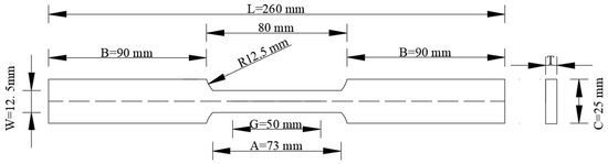
Figure 1.
Specimen cutting plane for the experimental test.
2.1.2. Experimental Setting
Hydrogenation of steels.
To achieve hydrogen insertion into the steel specimens, the constant current cathodic charging model [28] was applied. The specimens were immersed in a hydrochloric acid (HCl) solution with a concentration of 38%. A copper rod was used as the anode, and the steel specimens served as cathodes. A 220 V-4A power supply was used to provide a constant current of 3.2 amperes, with the positive pole connected to wires arranged in series on the steel specimens and the negative pole connected to the copper electrode, as shown in Figure 2. The proper functioning of the electrolysis process was confirmed by the appearance of hydrogen bubbles in the solution.
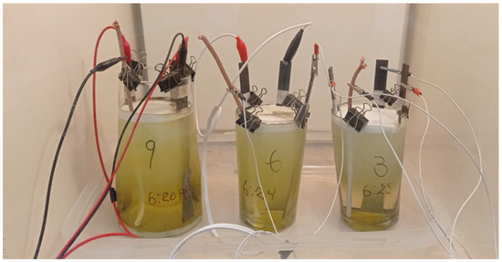
Figure 2.
Settings of the cathodic charge on the specimens.
Equation (1) [8] expresses the hydrogen concentration in the sample, (mol/cm3), based on Faraday’s law [29,30], where is the number of electrons involved in the electrochemical reaction (1), and is the effective volume of the specimen. Table 2 shows that the amount of absorbed hydrogen in the steel specimens increases proportionally with exposure time. Atomic hydrogen generated at the cathode diffused into the metallic lattice of the steel, promoting hydrogen embrittlement, which is consistent with theoretical predictions.
Table 2.
Hydrogen concentration in steel.
Tensile tests.
After the hydrogen exposure period, 120 Ω strain gauges were mounted along the effective gauge length of the steel specimens. The gauges recorded strain at a sampling rate of 1 kHz in order to determine the Young’s modulus of the materials. For this purpose, a National Instruments strain gauge register was used, connected to a computer running LabView software 2017 (see Figure 3). Additionally, during the tensile tests, force and displacement were continuously recorded at a rate of 100 scans/s until fracture using a Shimadzu universal testing machine (max. cap. 500 kN). A constant loading rate of 3 MPa/s was applied to all specimens. Three tensile tests were conducted for each condition to assess the repeatability of the measurements. The coefficient of variation (CV) for the mechanical properties was below 3% for the specimens without hydrogen exposure and below 10% for those exposed to hydrogen, demonstrating good reproducibility and consistency across tests. Consequently, only the results of a representative test are presented for each condition.
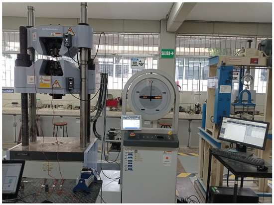
Figure 3.
Settings of the tensile test.
Metallography method.
After the steels were subjected to cathodic hydrogenation and tensile testing, metallographic specimens were prepared according to ASTM E3–95 [31], which provides a systematic procedure for revealing, identifying, and analyzing the microstructure of metals. Initially, each specimen was selected and sectioned at a distance no greater than two centimeters from the necking zone, to ensure observation of the areas most affected by stress. Subsequently, the specimens were mounted in resin and meticulously polished to obtain a smooth surface that would not alter the internal microstructure. For phase revelation, a solution of nitric acid in alcohol was applied for five seconds, highlighting microstructural features. Finally, the specimens were examined under an optical microscope to identify phases, inclusions, and potential defects [32], with the information obtained correlated with the mechanical properties derived from the tensile tests.
2.2. Numerical Calculations
In this section, the computational package Ansys Workbench (version 2024 R2) was used. The Static Structural module was employed to simulate hydrogen embrittlement during tensile tests up to the ultimate load of the material. The models used for the plastic characterization of the material were the Power Law Nonlinear Isotropic Hardening (PLNIH) and the Gurson–Tvergaard–Needleman (GTN) Method [33]. The displacement approach was used, which iteratively applies the Newton-Raphson method until convergence is achieved [34]. The steps for the ultimate load analysis in Ansys Workbench include: definition of the elastic and plastic mechanical properties of the material, meshing, application of boundary conditions and loads, and ultimate load calculation [35].
2.2.1. Description of the Model
The geometry of the specimens was modeled using solid hexahedral elements. Three different mesh configurations were tested to assess mesh convergence. For the general grip section, a mesh size of 10 mm was used, while the reduced parallel section—the region of interest—was refined with element sizes of 2 mm, 1.5 mm, and 1 mm. The final mesh adopted consisted of 10 mm elements in the grip section and 1 mm elements in the reduced section, ensuring four elements through the thickness for 4 mm specimens (ASTM A131 steel) and two elements for 2 mm specimens (A36 steel). This meshing strategy was applied to both steels, as illustrated in Figure 4.
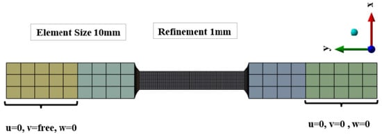
Figure 4.
Mesh, boundary condition and load of the models. The colored regions represent the gripping areas, while the black section corresponds to the reduced parallel length.
To replicate the experimental tensile test, boundary conditions were applied by fully constraining the lower end of the 50 mm grip section on both faces, meaning that displacements in the x, y, and z directions were set to zero. This corresponds to the clamping length of the universal testing machine. At the upper end, a controlled displacement was imposed on both faces, restricting movement in the x and z directions while allowing displacement along the y direction. The mesh convergence study showed that the percentage difference in ultimate stress between the last two mesh refinements was below 1%, confirming that the selected mesh provided sufficiently accurate results.
2.2.2. Description of Plastic Behavior of the Materials
The GTN model is combined with the PLNIH model to characterize the plastic behavior and damage evolution in ductile metals with porosity. In such cases, the material experiences void growth, nucleation, and coalescence. As porosity increases, material degradation intensifies, resulting in a reduced load-carrying capacity. The governing expressions of this combined model are presented below:
The GTN model is presented in Equation (2) [36], where σe, σy, and p denote the von Mises equivalent stress, yield stress, and hydrostatic pressure, respectively. The Tvergaard–Needleman constants were set as q1 = 1.5, q2 = 1.0, q3 = 2.5 for ductile steels [36,37,38]. The modified void volume fraction f* is employed to represent the degradation in load-carrying capacity due to void coalescence. However, in this analysis, void coalescence was not considered, as the numerical simulations were carried out only up to the material’s ultimate tensile strength.
Equation (3) [33] presents PLNIH model, where σo, N represent the initial yield stress and the strain hardening exponent, respectively. These parameters were derived from the experimental tensile tests conducted as part of this study. The mechanical properties of ASTM A131 and A36 steels, including their respective coefficients of variation, as obtained from these tests, are summarized in Table 3 and Table 4. Additionally, the initial porosity f0, included in the GTN model, accounts for hydrogen-induced voids, which have a significant effect on the mechanical behavior of the material.
Table 3.
Mechanical Properties of A131 Steel.
Table 4.
Mechanical Properties of A36 Steel.
The rate of change in void volume fraction is governed by two mechanisms: void growth and void nucleation, as described in Equations (4)–(6) [36]. The first mechanism occurs when the solid matrix is subjected to a hydrostatic tensile state. Under such conditions, the increase in void volume fraction due to growth is proportional to the rate of volumetric plastic strain. The second mechanism, void nucleation, takes place during plastic deformation when new voids are generated. In this study, void nucleation is modeled as a strain-controlled process using nucleation parameters—mean strain and standard deviation —adopted from experimental results [36,39].
3. Results and Discussion
To evidence HE in the steels, the dimensions of the specimens were recorded before hydrogen exposure and after the tensile tests. From these measurements, along with the force–displacement curves of each test, the elastic and plastic mechanical properties of the materials were obtained. The parameters considered included: Young’s modulus (E), yield stress (σy), ultimate stress (σu), tenacidad (Ut), and ductility in terms of final elongation (Lf). This section presents the variation in mechanical properties due to HE in ASTM A131 and A36 steels. Tensile test results for A36 steel after 12 h of hydrogen exposure are not shown, since one specimen exposed for 9 h fractured prematurely during the cathodic charging process, before the tensile test could be performed, see Figure 5.
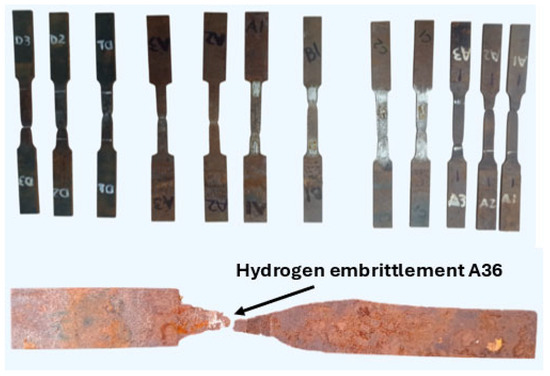
Figure 5.
Specimens of A36 and A131 steels after hydrogen charging and tensile testing, highlighting the hydrogen embrittlement observed in A36 steel after 9 h of exposure.
3.1. Experimental Analysis
Figure 6 shows the stress–strain curves for ASTM A131 and A36 steels subjected to different exposure times to hydrogen: 0, 3, 6, 9, and 12 h. The strength of the steels decreases progressively with increasing exposure time to hydrogen. As the hydrogen concentration in the specimens increases, the fracture stress is reached more quickly, indicating a degradation of their mechanical properties. Additionally, a loss of ductility is observed in both steels, with a more pronounced effect in A131 due to its higher strength. This behavior confirms the theory that high-strength steels are more susceptible to HE [40].
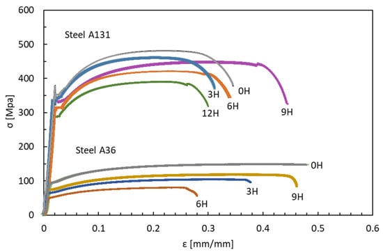
Figure 6.
Stress—Strain, Steel ASTM A131-A36.
Figure 7 presents the evolution of the mechanical properties of A131 and A36 steels as a function of hydrogen charging time, including Young’s modulus, yield stress, ultimate tensile stress, toughness, and ductility. Figure 7a shows the variation in yield and ultimate stresses. For A131 steel, ultimate strength decreased by 4%, 12%, 7%, and 19%, and yield stress by 13%, 17%, 11%, and 25% after 3, 6, 9, and 12 h of hydrogen exposure, respectively. For A36 steel, ultimate strength decreased by 30%, 47%, and 20%, and yield stress by 32%, 44%, and 19% after 3, 6, and 9 h, respectively. A temporary hardening effect was observed after 9 h of hydrogen charging, likely associated with transient saturation, hydrogen trapping at defects or dislocations, or microstructural rearrangements, as reported in the literature [41,42]. Figure 7b presents the variation in Young’s modulus. After 3 h of exposure, increases of 4% for A131 and 9% for A36 were recorded compared to uncharged specimens. After 6 h, reductions of 6% and 16% were observed, respectively. At longer exposure times, A131 showed decreases of 5% and 3% after 9 and 12 h, while A36 exhibited a slight increase of 2% at 9 h. These variations are attributed to interactions between hydrogen and the microstructure. Figure 7c shows the toughness results. A131 exhibited consistently higher toughness than A36; however, both materials experienced degradation after 6 h of hydrogen exposure, with reductions of 14% and 61%, respectively. Although a temporary increase was observed after 9 h, the overall trend remained downward, reaching a 30% reduction for A131 after 12 h. Figure 7d presents the evolution of ductility, evaluated through elongation. Both steels showed progressive reductions over time, with the largest decreases observed after 3 h for A131 (28%) and after 6 h for A36 (26%). Despite this, A36 retained higher ductility throughout the tests, suggesting better suitability for structural applications under prolonged hydrogen exposure.
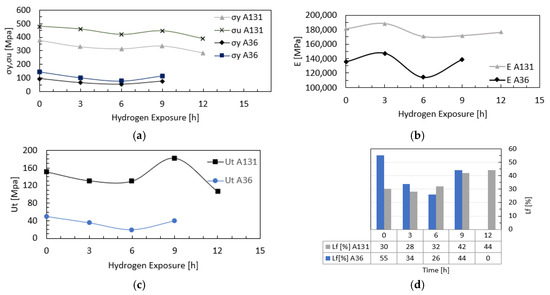
Figure 7.
Hydrogen Effect on Mechanical Properties of A131 and A36 Steels: (a) yield stress and ultimate tensile stress; (b) Young’s modulus; (c) toughness; and (d) ductility.
3.2. Metallographic Analysis
Microscopy images of the A131 steel specimens at 200× and 400× magnifications are presented in Figure 8. For the specimens without hydrogen exposure, the microstructure was predominantly composed of ferrite and pearlite, with a possible presence of bainite in higher-strength grades, as well as a non-uniform distribution of manganese sulfide (MnS) and complex oxide inclusions. In the specimens subjected to 3 h of hydrogen charging, grain boundaries were not clearly distinguishable; however, two deep scratches were observed on the material surface, along with some visible inclusions. For the specimens exposed to hydrogen for 6 h, the average grain size was 6.72 µm. Dark spots were observed, attributed to interactions between hydrogen and existing compounds or inclusions in the steel, such as oxides or carbides. In the specimen’s hydrogen-charged for 12 h, elongated irregular grains were identified, likely due to plastic deformation, along with inclusions, intergranular decohesion, and micro-pitting. The presence of these defects provides clear evidence of hydrogen embrittlement in the material.
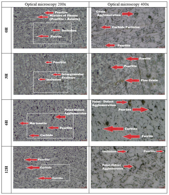
Figure 8.
Microscopy of A131 steel specimens.
Microscopy images of the A36 steel specimens at 200× and 400× magnifications are presented in Figure 9. In the specimens without hydrogen exposure, a bimodal microstructure was observed, consisting of ferrite (light grains) and pearlite colonies (dark grains) heterogeneously distributed, with an average grain size of 9.93 µm. After 3 h of hydrogen charging, the grain size increased to 16.89 µm, suggesting that hydrogen enhances grain boundary mobility by lowering the energy barriers that limit their movement, thus promoting the growth of larger grains at the expense of smaller ones. For the specimens subjected to 6 h of hydrogen charging, the average grain size was 13.85 µm, and a more pronounced intergranular decohesion was observed, along with a brownish stain surrounding an inclusion, indicating possible metallurgical phenomena or localized chemical reactions. In the specimens exposed for 9 h, the average grain size was 13.83 µm, with irregular grain morphology and elongated boundaries. Hydrogen diffusion into the material reduced atomic cohesion at grain boundaries, promoting the formation of coalescent micro-voids that facilitate intergranular fracture, thereby compromising the mechanical strength of steels used in naval applications.
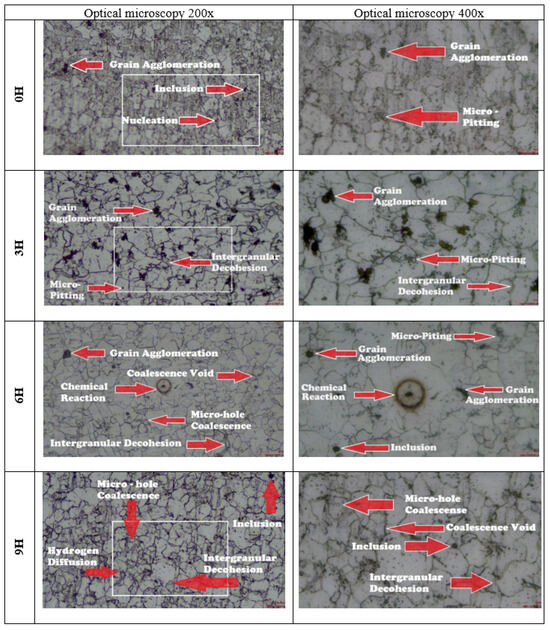
Figure 9.
Microscopy of A36 steel specimens.
3.3. Numerical Analysis
To develop a model that accurately simulates the load and deformation behavior observed in the tensile tests, a comparison was made between the experimental and numerical results, as shown in Figure 10. In this analysis, the numerical model validation was performed using the stress–strain curves of ASTM A131 and A36 steels, exposed to hydrogen for 12 and 9 h, respectively. By adjusting the parameters of the combined GTN-PLNIH model, a good match was achieved in the overall trend and behavior of the curves. However, a small gap was observed between the experimental and numerical curves in the region adjacent to the yield limit, which can be attributed to the strain hardening exponent, whose influence was not considered in this phase of the analysis.
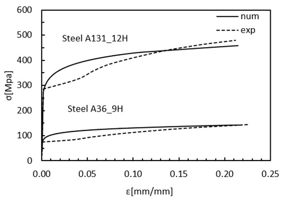
Figure 10.
Stress vs. Strain numerical-experimental validation.
Once validated, the numerical model was applied to the remaining cases, as shown in Figure 11. The stress–strain curves up to the ultimate stress exhibit trends consistent with the experimental results, with ultimate strength decreasing proportionally as hydrogen concentration increases. Notably, models with 9 h exposure show a deviation from this pattern, likely due to interactions between hydrogen and the material’s grains, as suggested in the literature. In addition, the initial porosity selected for each model, with or without hydrogen exposure, plays a crucial role in defining the material’s strength and ductility. Higher initial porosity accelerates the nucleation and coalescence of voids, reducing the area under the curve in the plastic region. This behavior reflects the typical loss of ductility and the onset of hydrogen embrittlement in steels, highlighting the combined influence of microstructural interactions and porosity on mechanical performance under hydrogen exposure.
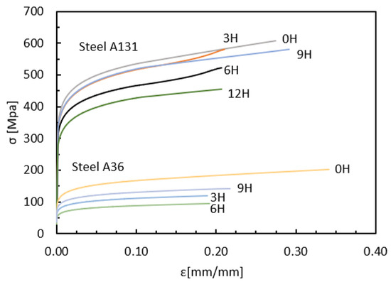
Figure 11.
FEM Stress–Strain Behavior of Steel under Hydrogen Exposure.
The normal stresses in the “y” direction for the models A131_0H, A131_12H, A36_0H, and A36_9H are shown in Figure 12 and Figure 13, evaluated at the point of ultimate stress for each model. In all cases, the onset of necking is observed, with this effect being more pronounced in models without hydrogen exposure, that is, zero initial porosity. For models with hydrogen exposure, necking is less evident, highlighting the increased brittleness induced by hydrogen. These results indicate that hydrogen not only reduces ductility but also alters the stress distribution during plastic deformation, potentially affecting the failure mode of the steels.
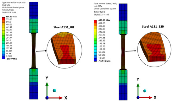
Figure 12.
Normal Stress in “y” direction of Steel A131.
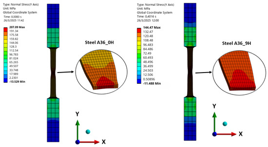
Figure 13.
Normal Stress in “y” direction of Steel A36.
4. Conclusions
This study evaluated the effects of hydrogen exposure on naval steels ASTM A131 and A36, combining experimental testing and numerical simulation. Key findings and contributions are:
- Mechanical degradation: Both steels showed progressive reductions in strength and toughness after 6 h of hydrogen exposure. A transient hardening occurred at 9 h, but long-term properties declined. Maximum reductions in ultimate tensile strength were 19% (A131) and 47% (A36), with toughness decreasing by 39% and 61%, respectively.
- Material performance: A131 exhibited superior mechanical behavior compared to A36 under all exposure conditions.
- Microstructural damage: Hydrogen embrittlement produced inclusions, intergranular decohesion, cracks, micro-pitting, and fissures, increasingly severe with longer exposure.
- Numerical modeling: A GTN-PLNIH FEM model accurately predicted tensile behavior, demonstrating the critical role of initial porosity in accelerating void nucleation and coalescence, leading to reduced toughness and increased brittleness.
- Practical implications: Results highlight the detrimental effect of hydrogen and the importance of mitigation strategies, such as protective coatings and optimized design, for naval and industrial structures in hydrogen-rich environments.
Overall, this work provides a concise experimental and numerical framework for predicting hydrogen-induced degradation in naval steels, offering insights to improve structural design and safety under hydrogen exposure.
Author Contributions
Conceptualization, J.I.M., M.D.S. and M.D.S.; methodology, J.I.M., R.I.C., L.C. and M.I.L.; software, J.I.M. and R.I.C.; formal analysis, J.I.M. and M.D.S.; investigation, J.I.M.; resources, J.I.M. and L.C.; writing—original draft preparation, J.I.M.; writing—review and editing, L.C. and M.I.L.; visualization, J.I.M.; supervision, L.C. All authors have read and agreed to the published version of the manuscript.
Funding
This research received no external funding.
Institutional Review Board Statement
Not applicable.
Informed Consent Statement
Not applicable.
Data Availability Statement
The original contributions presented in this study are included in the article. Further inquiries can be directed to the authors.
Conflicts of Interest
The authors declare no conflicts of interest.
References
- Kut, J.P.; Pietrucha-Urbanik, K.; Zeleňáková, M. Assessing the role of hydrogen in sustainable energy futures: A comprehensive bibliometric analysis of research and international collaborations in energy and environmental engineering. Energies 2024, 17, 1862. [Google Scholar] [CrossRef]
- Mohamed Elshafei, J.A.; Mansour, R. Green hydrogen as a potential solution for reducing carbon emissions: A review. J. Energy Res. Rev. 2023, 13, 1–10. [Google Scholar] [CrossRef]
- Dadfarnia, M.; Nagao, A.; Wang, S.; Martin, M.L.; Somerday, B.P.; Sofronis, P. Recent advances on hydrogen embrittlement of structural materials. Int. J. Fract. 2015, 196, 223–243. [Google Scholar] [CrossRef]
- Andeobu, L.; Wibowo, S.; Grandhi, S. Renewable hydrogen for the energy transition in Australia—Current trends, challenges and future directions. Int. J. Hydrogen Energy 2024, 87, 1207–1223. [Google Scholar] [CrossRef]
- Ruggieri, C.; Sarzosa, D.F.B.; Paredes, M. A local stress criterion to assess the effects of hydrogen embrittlement on the fracture strength of notched tensile specimens. Theor. Appl. Fract. Mech. 2023, 127, 104045. [Google Scholar] [CrossRef]
- Cao, J. Effect of hydrogen embrittlement on the safety assessment of low-strength hydrogen transmission pipeline. Eng. Fail. Anal. 2024, 156, 107787. [Google Scholar] [CrossRef]
- Shehata, M.F.; El-Shamy, A.M. Hydrogen-based failure in oil and gas pipelines a review. Gas Sci. Eng. 2023, 115, 204994. [Google Scholar] [CrossRef]
- Zhang, R.; Ai, S.; Long, M.; Wan, L.; Li, Y.; Jia, D.; Duan, H.; Chen, D. Quantitative study on hydrogen concentration–hydrogen embrittlement sensitivity of X80 pipeline steel based on hydrogen permeation kinetics. Metals 2024, 14, 763. [Google Scholar] [CrossRef]
- Rivera-Vargas, G.A.; Matsumoto-Kuwabara, Y.; Baquero-Parra, R. Análisis para la obtención de hidrógeno a partir de biogás proveniente de la fermentación de bebidas naturales. Ing. Investig. Tecnol. 2016, 17, 251–256. [Google Scholar] [CrossRef][Green Version]
- Ghadiani, H.; Farhat, Z.; Alam, T.; Islam, M.A. Assessing hydrogen embrittlement in pipeline steels for natural gas-hydrogen blends: Implications for existing infrastructure. Solids 2024, 5, 375–393. [Google Scholar] [CrossRef]
- Hino, M.; Mukai, S.; Shimada, T.; Okada, K.; Horikawa, K. Inferences of baking time on hydrogen embrittlement for high strength steel treated with various zinc based electroplating. Mater. Sci. Forum 2021, 1016, 156–161. [Google Scholar] [CrossRef]
- Mihi, A.; Benbouta, R.; Abbassi, A.; Cottis, R. Simulated heat affected zone hardness limits of C-Mn steels used in offshore structures. Mater. Corros. 2006, 57, 766–770. [Google Scholar] [CrossRef]
- Novak, P.; Yuan, R.; Somerday, B.P.; Sofronis, P.; Ritchie, R.O. A statistical, physical-based, micro-mechanical model of hydrogen-induced intergranular fracture in steel. J. Mech. Phys. Solids 2010, 58, 206–226. [Google Scholar] [CrossRef]
- Sun, D.; Han, G.; Vaodee, S.; Fukuyama, S.; Yokogawa, K. Tensile behaviour of type 304 austenitic stainless steels in hydrogen atmosphere at low temperatures. Mater. Sci. Technol. 2001, 17, 302–308. [Google Scholar] [CrossRef]
- Lee, S.J.; Ronevich, J.A.; Krauss, G.; Matlock, D.K. Hydrogen embrittlement of hardened low-carbon sheet steel. ISIJ Int. 2010, 50, 294–301. [Google Scholar] [CrossRef]
- Wang, Z.; Huang, M. Improving hydrogen embrittlement resistance of hot-stamped 1500 MPa steel parts that have undergone a Q&P treatment by the design of retained austenite and martensite Matrix. Metals 2020, 10, 1585. [Google Scholar] [CrossRef]
- Drichel, A.; Spiewak, M.; Röttger, A.; Lützenkirchen-Hecht, D.; Rodrigues, B.V.M.; Slabon, A. Hydrogen Economy vs. Hydrogen Embrittlement: Indirect Electrochemical Determination of Hydrogen Diffusion in Steel. ACS Sustain. Chem. Eng. 2024, 12, 13142–13153. [Google Scholar] [CrossRef]
- Takasugi, T.; Hanada, S. Environmental embrittlement of boron-doped Ni3(Al, Ti) single crystals at room temperature. J. Mater. Res. 1993, 8, 2534–2542. [Google Scholar] [CrossRef]
- Borchers, C.; Michler, T.; Pundt, A. Effect of hydrogen on the mechanical properties of stainless steels. Adv. Eng. Mater. 2008, 10, 11–23. [Google Scholar] [CrossRef]
- Komoda, R.; Kubota, M.; Staykov, A.; Ginet, P.; Barbier, F.; Furtado, J. Inhibitory effect of oxygen on hydrogen-induced fracture of A333 pipe steel. Fatigue Fract. Eng. Mater. Struct. 2019, 42, 1387–1401. [Google Scholar] [CrossRef]
- Scheider, I.; Pfuff, M.; Dietzel, W. Simulation of hydrogen assisted stress corrosion cracking using the cohesive model. Eng. Fract. Mech. 2008, 75, 4283–4291. [Google Scholar] [CrossRef]
- Ahn, D.C.; Sofronis, P.; Dodds, R. Modeling of hydrogen-assisted ductile crack propagation in metals and alloys. Int. J. Fract. 2007, 145, 135–157. [Google Scholar] [CrossRef]
- Toribio, J. Numerical modelling of hydrogen embrittlement of cylindrical bars with residual stress fields. J. Strain Anal. Eng. Des. 2000, 35, 189–203. [Google Scholar] [CrossRef]
- Gong, X.; Lei, R.; Sun, R.; Jiang, X.; Su, Y.; Yan, Y. An ensemble learning strategy for multi-source hydrogen embrittlement data by introducing missing information. Mater. Genome Eng. Adv. 2024, 2, e35. [Google Scholar] [CrossRef]
- Lamas, M.I.; Rodriguez, C.G. Numerical model to analyze NOx reduction by ammonia injection in diesel-hydrogen engines. Int. J. Hydrogen Energy 2017, 42, 26132–26141. [Google Scholar] [CrossRef]
- Troya, J.J.; Álvarez, C.; Fernández-Garrido, C.; Carral, L. Analysing the possibilities of using fuel cells in ships. Int. J. Hydrogen Energy 2016, 41, 2853–2866. [Google Scholar] [CrossRef]
- ASTM C1709-18; Standard Test Methods for Tension Testing of Metallic Materials (E8/E8M—08). Vol. 08, no. Reapproved 1989. ASTM International: West Conshohocken, PA, USA, 2000; pp. 3–4. [CrossRef]
- García, T.E.; Arroyo, B.; Rodríguez, C.; Belzunce, F.J.; Álvarez, J.A. Small punch test methodologies for the analysis of the hydrogen embrittlement of structural steels. Theor. Appl. Fract. Mech. 2016, 86, 89–100. [Google Scholar] [CrossRef]
- Capelle, J.; Dmytrakh, I.; Pluvinage, G. Comparative assessment of electrochemical hydrogen absorption by pipeline steels with different strength. Corros. Sci. 2010, 52, 1554–1559. [Google Scholar] [CrossRef]
- Cupertino-Malheiros, L.; Duportal, M.; Hageman, T.; Zafra, A.; Martínez-Pañeda, E. Hydrogen uptake kinetics of cathodic polarized metals in aqueous electrolytes. Corros. Sci. 2024, 231, 111959. [Google Scholar] [CrossRef]
- ASTM E3-01; Standard Practice for Preparation of Metallographic Specimens. ASTM International: West Conshohocken, PA, USA, 1995.
- ASM International. ASM Handbook: Metallography and Microstructures; ASM International: Materials Park, OH, USA, 2004; Volume 9. [Google Scholar]
- Ansys. Material Reference 2024R2. 2024, pp. 13–345. Available online: http://www.ansys.com (accessed on 26 March 2025).
- Madenci, E.; Guven, I. The Finite Element Method and Applications in Engineering Using ANSYS, 2nd ed.; Springer: Boston, MA, USA, 2015. [Google Scholar]
- Mendoza, J.I.; Marín-López, J.R. Ultimate local strength of a submarine structure considering the influence of localized reduction of thickness. Ocean Eng. 2023, 271, 113778. [Google Scholar] [CrossRef]
- Tvergaard, V.; Needleman, A. Analysis of the cup-cone round tensile fracture. Acta Metall. 1984, 32, 157–169. [Google Scholar] [CrossRef]
- Springmann, M.; Kuna, M. Identification of material parameters of the Gurson—Tvergaard—Needleman model by combined experimental and numerical techniques. Comput. Mater. Sci. 2005, 33, 501–509. [Google Scholar] [CrossRef]
- Vadillo, G. An analysis of Gurson model with parameters dependent on triaxiality based on unitary cells. Eur. J. Mech. A/Solids 2009, 28, 417–427. [Google Scholar] [CrossRef]
- Depraetere, R.; De Waele, W.; Hertelé, S. Fully-coupled continuum damage model for simulation of plasticity dominated hydrogen embrittlement mechanisms. Comput. Mater. Sci. 2021, 200, 110857. [Google Scholar] [CrossRef]
- Dowling, N.E. Mechanical Behavior of Materials, 4th ed.; PEARSON: London, UK, 2015; pp. 334–400. [Google Scholar]
- Iost, A.; Vogt, J.B. Hardness variation in a cathodic hydrogen-charged austenitic stainless steel. Scr. Mater. 1997, 37, 1499–1504. [Google Scholar] [CrossRef]
- Candia, G.L.; Brandaleze, E.; Mansilla, G.A. Study of the effect of hydrogen on the microhardness of steels. Rev. Cienc. Tecnol. 2013, 19, 64–68. [Google Scholar]
Disclaimer/Publisher’s Note: The statements, opinions and data contained in all publications are solely those of the individual author(s) and contributor(s) and not of MDPI and/or the editor(s). MDPI and/or the editor(s) disclaim responsibility for any injury to people or property resulting from any ideas, methods, instructions or products referred to in the content. |
© 2025 by the authors. Licensee MDPI, Basel, Switzerland. This article is an open access article distributed under the terms and conditions of the Creative Commons Attribution (CC BY) license (https://creativecommons.org/licenses/by/4.0/).