Article

Reduction in Reflection Signal Losses in Complex Terahertz Optical Elements Through Tailored Oil Application

1
Faculty of Physics, Warsaw University of Technology, Koszykowa 75, 00-662 Warsaw, Poland
2
Institute of Micromechanics and Photonics, Faculty of Mechatronics, Warsaw University of Technology, Św. A. Boboli 8, 02-525 Warsaw, Poland
*
Author to whom correspondence should be addressed.
Appl. Sci. 2025, 15(20), 11167; https://doi.org/10.3390/app152011167
Submission received: 12 September 2025 / Revised: 3 October 2025 / Accepted: 16 October 2025 / Published: 17 October 2025

Abstract

In complex terahertz (THz) systems, multiple optical elements are often combined to achieve advanced functionalities. However, unwanted Fresnel reflections at their interfaces and between components lead to parasitic interference effects and signal losses. This study presents oil-based refractive-index-matching fillers integrated with additively manufactured assemblies to suppress Fresnel reflections and enhance overall optical system performance. The optical properties of 20 plant-based, synthetic, and mineral oils were investigated using terahertz time-domain spectroscopy (THz TDS). Furthermore, a multilayer structure was designed and experimentally verified, fabricated via fused deposition modeling (FDM) using highly transparent cyclic olefin copolymer (COC). The results demonstrate that the use of tailored oils reduces Fresnel reflection signal losses and also mitigates parasitic interference within the system, thereby improving the effective efficiency of the optical system. Additionally, THz TDS measurements on multilayer structures revealed that, in imaging configurations, the application of refractive-index-matched oils increases the signal gain by 2.33 times. These findings highlight the potential of oil-based index-matching fillers for imaging multilayered objects and mitigating delamination effects in optical elements.

1. Introduction

In recent years, the rapid development of terahertz (THz) technology has significantly contributed to the advancement of numerous implemented and future technological applications in fields such as medicine and biology [1,2,3], telecommunications [4,5], security systems [6], and non-destructive testing [7]. Each of these applications requires specialized optical systems capable of precise beam shaping in transmission and/or reflection modes [8]. This is achievable by implementing various types of passive optical elements, including refractive, diffractive, or hybrid components, depending on specific application requirements [9,10].
In research units, prototyping THz passive optical elements relies increasingly on additive manufacturing technologies, such as fused deposition modeling (FDM), selective laser sintering (SLS), and digital light processing (DLP) [11,12]. This phenomenon is the result of the high printing resolution compared to the THz radiation wavelengths, allowing the fabrication of efficient elements even for frequencies as high as 1 THz [13]. Furthermore, polymer materials used in 3D printing technologies exhibit desirable optical properties, particularly those relevant to FDM technology [14,15]. These polymers exhibit low absorption coefficients and refractive indices in the range of 1.45–1.65 within the THz region. Examples of such materials include cyclic olefin copolymer (COC) [16,17], polypropylene (PP) [14], styrene–butadiene copolymer (SBC) [15], and high-impact polystyrene (HIPS) [14]. Moreover, these polymers possess optical properties similar to polytetrafluoroethylene (PTFE), a material commonly used in commercial lens manufacturing [18]. Additive manufacturing further enables the low-cost, single-unit, detailed production of optical structures with significantly more complex spatial profiles compared to commercially available components, which is especially beneficial in the case of diffractive optical elements [19,20].
The growing requirements of THz technology demand increasingly sophisticated solutions in the implementation of optical systems, often involving the use of multiple connected optical elements. One example is the THz achromatic doublets, which reduce chromatic aberration (dispersion) by combining multiple optical elements made of various materials with different spatial profiles. Another example involves solutions aimed at enhancing system efficiency through the integration of multiple diffractive optical elements, such as those employed for spatial multiplexing of THz signals, which are described in detail in our previous studies [21]. However, despite the improved efficiency of innovative solutions, combining two or multiple optical elements introduces signal losses due to Fresnel reflections. These reflections arise from significant differences in refractive indices, often caused by air gaps between adjacent optical elements. In addition to signal losses, Fresnel reflections can lead to parasitic signal interferometric effects, particularly in systems utilizing highly coherent THz radiation sources such as Schottky-diode-based mixer–amplifier–multiplier chains (e.g., manufactured by Virginia Diodes Inc. (VDI)), Impact Ionization Avalanche Transit-Time (IMPATT) diodes, or Resonant Tunneling Diodes (RTDs) [22]. These undesired reflections result in a decrease in the efficiency of optical systems as well as various unexpected signal amplification in measurements caused by the interferometric effects [23].
One solution to this issue is the application of an appropriate coupling medium to fill the air gaps between adjacent optical elements. This approach minimizes the refractive index difference between optical components, thereby reducing the impact of unwanted Fresnel reflections. However, water-based adhesives (a significant portion of glues) are unsuitable for this purpose due to their high absorption of THz radiation and inappropriate refractive index values caused by the water component [24,25]. Additionally, some of the immersion oils applicable for visible optics also significantly attenuate THz radiation [26]. The refractive index matching with THz optical components from 1.5 to 1.8 can be achieved using unconventional materials such as waxes, paraffins, or even chocolate [15]. However, these solutions are not practical for real applications due to material deformations and internal stresses that arise during the cooling process. For higher refractive indices, from 1.8 to 5.0, a matching solution based on barium titanate (BaTiO3) particles dispersed in benzocyclobutene (BCB) can be employed [27]. Nevertheless, alternative approaches are still required to enable reliable refractive index matching with polymers commonly used for the fabrication of THz passive optical components with refractive indices from 1.5 to 1.6.
In this study, the authors propose utilizing various oils of different origins—plant, mineral, and synthetic—as possible materials to reduce unwanted reflections. Detailed investigations into the optical properties of 20 different oils in the THz radiation range are presented in this research. The results allowed for the selection of oils compatible with polymer materials commonly used in the manufacturing of THz optical elements. Furthermore, THz time-domain spectroscopy (THz TDS) measurements conducted on multilayer structures demonstrated the degree of the influence of the parasitic signal reflections, occurring between optical components in THz optical setups, on the imaging quality. We show that the application of a proper oil filler significantly reduced the mentioned signal losses. The presented solution also finds application as the filler for delaminations that might be present in THz optical elements, as well as in the optical setups requiring the integration of various types of materials in one system, e.g., intended for different imaging applications.
Until now, previous studies on the optical properties of plant-based oils and animal fats using THz TDS concern only a limited range of materials and primarily focus on animal fats, and the influence of temperature on their optical properties [28]. Thus, this is the first time that a thorough study on different types of oils and their applicability for THz imaging is presented.

2. Materials and Methods

2.1. Optical Properties Investigation

The optical properties of 20 different oils were investigated using THz TDS. Measurements were conducted with the TeraPulse Lx Modular System (TeraView) operating in both transmission and reflection configurations. THz TDS is a technique that enables the determination of both the attenuation and the phase delay introduced by the investigated material within the terahertz frequency range, spanning approximately from 100 GHz to 4 THz for transparent materials measurements. In the THz TDS system, femtosecond laser pulses are split into two beams. One beam excites a photoconductive antenna, typically fabricated from a semiconductor such as GaAs, generating ultrashort THz pulses. These pulses are shaped and focused onto the sample by a set of mirrors, and after transmission through the sample, they are guided to a detector, which is also a photoconductive antenna. The second laser beam serves as a probe and is temporally delayed by an optical delay line, enabling time-resolved sampling of the THz pulses. This approach allows the reconstruction of both the amplitude and phase of the transmitted signal in the time domain. Applying the Fourier transform provides broadband spectral information [29,30]. Consequently, the analysis of the acquired data allows for the calculation of the absorption coefficient and refractive index of the investigated materials, which are crucial optical properties in the design and prototyping stage of the THz optical component creation process. A schematic diagram of the THz TDS setup operating in transmission mode is presented in Figure 1.
This study includes various types of oils of plant, mineral, and synthetic origin, including immersion oils commonly used in the visible spectrum. A detailed list of the oils, including their type, base component, and brand names, is presented in Table 1. The measurements in this study were conducted at room temperature. Variations in temperature may influence the optical properties of the investigated oils in the THz radiation range; however, this remains a topic for future research.
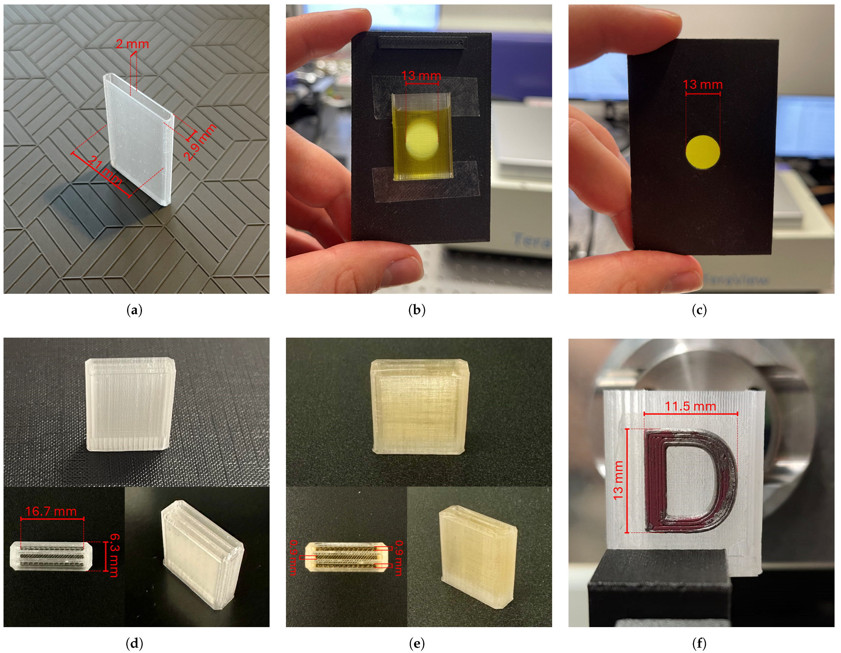
In order to investigate the optical properties of the oils listed in Table 1, special 3D-printed cuvettes were designed, into which the oils were inserted using a pipette. The external dimensions of each cuvette were 21 × 30 mm, and its thickness was 2.9 mm (including the empty space inside). The cuvettes were 3D-printed using FDM technology with COC material, which is highly transparent in the THz radiation range [16,17]. The printing parameters were carefully selected based on previous studies in this area to ensure maximum uniformity of the printed structure and minimal absorption losses [16]. Consequently, the cuvette walls were printed using a 0.4 mm diameter hardened steel nozzle with electroless nickel plating and a tungsten disulfide fullerene structure (WS2) nanoparticle coating. The walls of the cuvette were printed as a single line with a thickness of 0.45 mm. Thus, during the propagation of THz radiation through the sample, the radiation passed through a 2 mm thickness optical path of the investigated oil and 0.9 mm thickness (corresponding to the two walls) of the COC material. The layer thickness during cuvette printing was set for 100 µm, defining the vertical resolution of the manufactured cuvettes. All structures in this study (including cuvettes) were manufactured using the Prusa MK3S+ printer. The photograph of the empty printed cuvette is shown in Figure 2a.
Subsequently, the cuvettes were filled with oil and then attached to a 3D-printed holder manufactured from a polyethylene terephthalate glycol-modified (PETG) composite with a carbon fiber additive, which had a circular aperture with a diameter of 13 mm. The PETG composite with a carbon fiber additive is a strongly attenuating material in the THz radiation range [31]. Thus, during measurements, THz radiation propagated exclusively through the area defined by the aperture. Moreover, broadband tunable THz metamaterial absorbers based on graphene could also be employed in other optical systems, thereby providing additional functionality and versatility [32]. The photographs of the cuvette filled with an example of plant oil (oil 1 in Table 1) attached to the holder are shown in Figure 2b,c.
During THz TDS measurements, the holder with the sample was placed in a dry air chamber to eliminate the negative effects of water vapor present in the air [33,34]. For each sample, measurements were performed with a sample average value of 350. This part of the study focused on the determination of the absorption coefficient and refractive index values for the samples.
Additionally, the optical properties of cylindrical samples manufactured from COC with a diameter of 13 mm and a thickness of 4 mm were measured to determine the optical properties of the material used for cuvettes [15]. This allowed for the determination of the refractive index and absorption coefficient of the oils without the influence of the cuvette component. The absorption coefficient of the oils α 1 was calculated according to Equation (1), and the refractive index n 1 was determined using Equation (2).
α 1 = α d α 2 d 2 d 1 ,
n 1 = n d n 2 d 2 d 1 ,
where α represents the effective absorption coefficient of the entire sample (the combination of the absorption coefficients of the investigated oil and the 3D-printed cuvette), while α 1 and α 2 denote the absorption coefficients of the sample components: the investigated oil and the cuvette material (COC), respectively. Similarly, n is the effective refractive index of the entire sample (the combination of the refractive index of the investigated oil and the 3D-printed cuvette), and n 1 and n 2 represent the refractive index values of the oil and the cuvette material (COC), respectively. The total thickness of the sample d is expressed as the sum of the thickness of the inlet filled with oil d 1 and the thickness of the cuvette walls d 2 . The thickness d 1 is equal to 2 mm, while d 2 is equal to 0.9 mm.

2.2. Multilayer Structures Design, Manufacturing and Investigation Methods

In the second part of the study, emphasis was placed on determining the impact of parasitic Fresnel reflections, associated with signal losses, and on the method of their reduction using a selected synthetic filler oil (oil 18 in Table 1), whose optical properties are consistent with the COC material. For this purpose, a multilayer structure with three inlets was designed and subsequently 3D-printed using FDM technology from COC, following the printing parameters outlined in the previously mentioned study [16]. The multilayer structures were fabricated using a hardened steel nozzle with electroless nickel plating and a tungsten disulfide fullerene structure (WS2) nanoparticle coating with a diameter of 400 μm. Printing was carried out with a line width of 450 μm and a layer height of 100 μm, corresponding to the horizontal and vertical printing resolutions, respectively. The structures were manufactured at a nozzle temperature of 240, while the build plate temperature was maintained at 85. In addition, the build plate was coated with a layer of vinylpyrrolidone/vinyl acetate (VP/VA) copolymers to enhance adhesion and prevent undesired deformations of the print. Each inlet of the multilayer structure had a width of 900 µm, as did the walls separating them (wall thickness corresponding to two print lines). Consequently, the total thickness of the multilayer structure was equal to 6.3 mm.
The photograph of the empty multilayer structure is shown in Figure 2d, while Figure 2e presents the structure filled with the synthetic oil (oil 18 from Table 1). Additionally, Figure 2f shows the multilayer structure placed in the THz TDS measurement setup for scans in the reflection mode.
Initially, THz TDS measurements for the multilayer structure were conducted in the transmission mode within a chamber filled with dry air. The structure was mounted in the holder with a 13 mm diameter aperture manufactured from the PETG composite with carbon fiber additive. The empty structure was first examined, followed by filling each inlet with oil 18 (notations as in Table 1) and repeating the measurements. These measurements were utilized to determine the absorption coefficient and refractive index values of the multilayer structure in four different states. Conducting such studies enabled the identification of potential parasitic internal reflections (Fresnel reflections) within the structure, which can lead to signal loss and undesired interference effects. The THz TDS measurements were performed with sample averages set to 350.
Subsequently, the procedure was repeated for the THz TDS measurements in the reflection mode. This time, the entire structure was scanned with an attached object in the shape of the letter “D” at its back, with total dimensions of 11.5 mm by 13 mm. The “D”-shaped object was manufactured using FDM technology from polylactic acid (PLA) and subsequently coated with a few mirror spray layers (Forever Paints brand), significantly enhancing its reflectance. The scans were performed with a step size of 200 μm in both the horizontal and vertical directions.

3. Experimental Results

3.1. Optical Properties Measurements

The obtained experimental results of the optical properties of twenty different oils investigated using THz TDS in transmission mode within a chamber filled with dry air are presented in Figure 3. The presented data include the absorption coefficient (Figure 3a) and the refractive index (Figure 3b) values in the frequency domain, ranging from 100 GHz to 1.5 THz. In contrast, Figure 3c–f present enlarged sections in the frequency range from 0.5 THz to 0.7 THz, highlighting the differences in the optical properties of plant and fish oils, as well as mineral and synthetic oils. The notation of the oils follows the data presented in Table 1.
The presented optical properties in Figure Figure 3 clearly indicate that synthetic and mineral oils exhibit significantly lower absorption coefficients compared to other oils. Their refractive index values in the analyzed frequency range of 100 GHz to 2 THz fall within an approximate range of 1.47 to 1.50, depending on the oil. The dispersion of the mentioned oils was not observed. Their optical properties are similar to those of polymers such as COC, high-density polyethylene (HDPE), linear low-density polyethylene (LLDPE), PTFE, and PP [15], which are commonly used in the prototyping and production of THz passive optical elements due to the introduction of low attenuation in the THz radiation range. As a result, these oils may find applications in filling air gaps between highly transparent optical elements or addressing delaminations within optical components, thereby enhancing the performance of optical elements and systems.
All investigated plant oils and fish oil exhibit similar optical properties. Their absorption is significantly higher than synthetic and mineral oils. However, it remains comparable to (or even lower than) various polymers used in the prototyping of optical elements with 3D printing technologies [15]. For this group of oils, dispersion was observed in the frequency range of 100 GHz to 2 THz, which is associated with a change in the absorption coefficient within this range. The refractive index of the analyzed group was approximately equal to 1.55 at 750 GHz. This value corresponds to the refractive index of polymers such as styrene-butadiene copolymer (SBC), high-impact polystyrene (HIPS), acrylonitrile butadiene styrene (ABS), polyamide 12 (PA12), polymethyl methacrylate (PMMA), and some thermoplastic elastomers (TPE) in the THz radiation range [15].
The results also revealed that two immersion oils, which are transparent in the visible radiation range, significantly attenuate THz radiation. Such research is essential as it demonstrates that seemingly intuitive materials may not align with potential THz applications, whereas more “exotic” oils (like synthetic, mineral, or plant oils) may prove to be highly suitable. The refractive index of the mentioned immersion oils is equal to approximately 1.62 at 750 GHz.

3.2. Multilayer Structures Measurements

The optical properties of the multilayer structure were measured using THz TDS in transmission mode. The obtained results are presented in Figure 4. The analysis focused on the absorption coefficient and refractive index of the structure in the THz frequency domain, as these parameters play a crucial role in both the prototyping of passive optical components and their performance in optical systems. Initially, measurements were conducted on the structure with three empty inlets. Subsequently, the measurements were repeated in sequential stages, filling the successive inlets with synthetic oil 18 (as denoted in Table 1).
The results presented in Figure 4 clearly indicate a significant impact of the undesired Fresnel reflections in the investigated multilayer structure. When radiation is incident at the interface between two media with different refractive indices, a portion of the incident wave is reflected. In multilayer structures, multiple such reflections occur, and for certain frequencies, these reflections may interfere, leading to signal losses and signal disturbances in optical systems. These reflections manifest as periodic oscillations across the entire analyzed spectral range, affecting both the absorption coefficient and the refractive index values. The reflections introduce substantial signal losses, as evidenced by the significantly higher absorption coefficient observed in regions of quasi-absorption peaks caused by these reflections. Successively filling inlets with synthetic oil 18 significantly reduced the undesired reflection effects. For all three inlets filled, an almost complete elimination of Fresnel reflections and the corresponding signal losses was achieved.
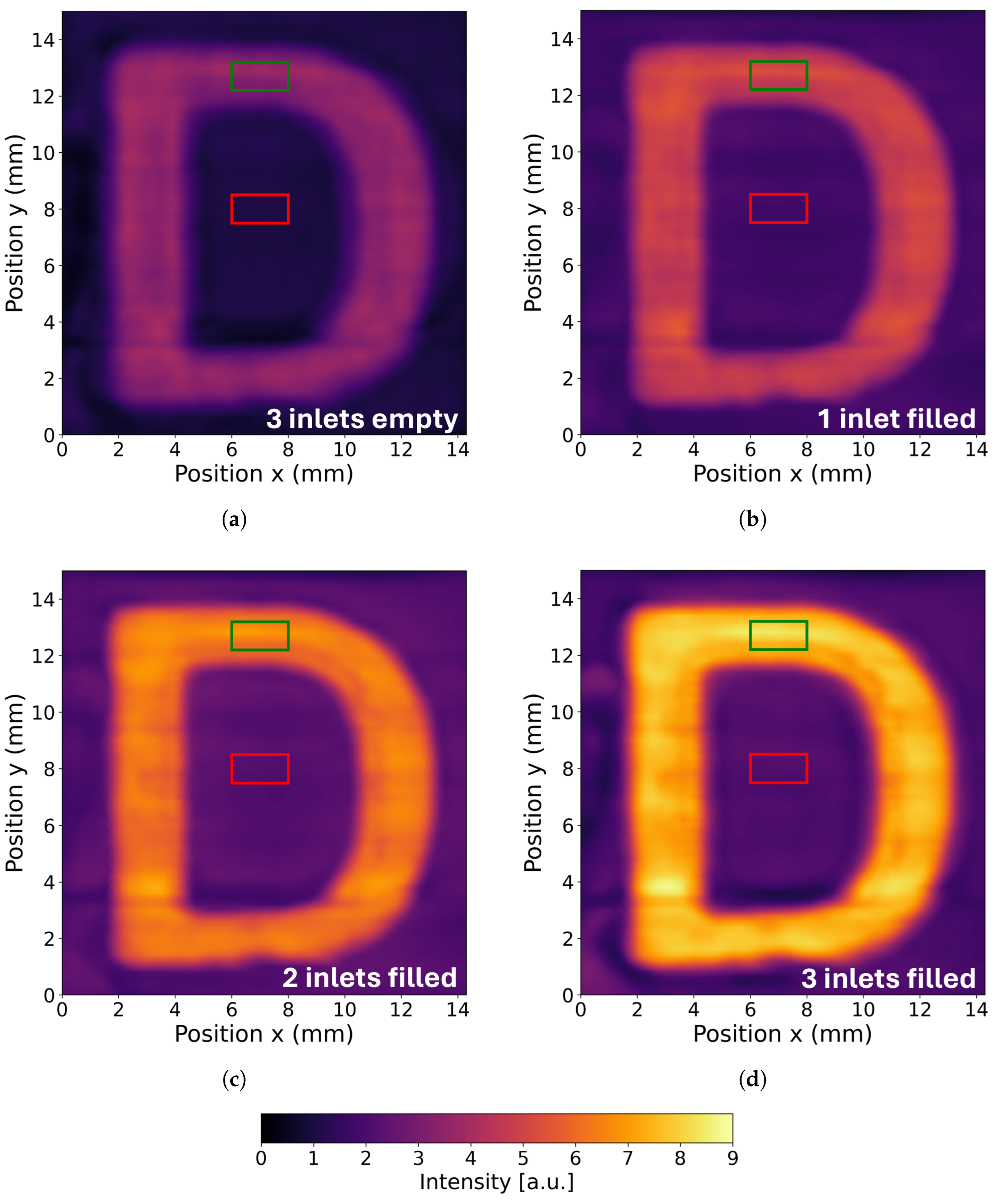
Subsequently, THz TDS measurements were performed in reflection mode by scanning the multilayer structure. The measurements were conducted on a structure designed and manufactured identically to the one used in the transmission measurements. However, in this setup, the highly reflective “D”-shaped object was additionally attached to the back surface of the structure, as illustrated in Figure 2f. Measurements were carried out with the three inlets being initially empty and then repeated after filling each inlet sequentially with the synthetic oil 18. The results of the peak-to-peak scans are shown in Figure 5. The presented data were processed using linear interpolation. Each scan highlights two areas of interest: the region marked in green represents the radiation reflected from the “D”-shaped object, while the region marked in red corresponds to the area where the recorded signal did not interact with the object.
The scans presented in Figure 5 indicate a reduction in parasitic Fresnel reflection losses, achieved by the refractive-index-matching of a suitable oil filler and the 3D-printed multilayer structure. Filling successive inlets with oil 18 results in an increase in the recorded signal reflected from the “D”-shaped object. The marked areas in Figure 5 were used for a quantitative analysis of the obtained results, which is presented in Table 2. The average registered intensities of the THz signal were determined for the indicated regions, where I object corresponds to the intensity reflected from the green area of the “D”-shaped object, while I background represents the intensity recorded for the red-marked area where the object was absent.
To analyze the reflected signal enhancement, the signal gain (G) parameter was calculated. The signal gain (G) was defined as the ratio of I o b j e c t ( f i l l e d ) for the multilayer structure with a specified number of inlets filled with synthetic oil 18 to I o b j e c t ( e m p t y ) , which corresponds to the average intensity measured for the structure with three empty inlets, as defined by Equation (3). In addition, the corresponding range of G values was determined by calculating its minimum G min and maximum G max bounds, as given by Equation (4) and Equation (5), respectively.
G = I o b j e c t ( f i l l e d ) I o b j e c t ( e m p t y ) ,
G min = I o b j e c t ( f i l l e d ) σ I o b j e c t ( f i l l e d ) I o b j e c t ( e m p t y ) + σ I o b j e c t ( e m p t y ) ,
G max = I o b j e c t ( f i l l e d ) + σ I o b j e c t ( f i l l e d ) I o b j e c t ( e m p t y ) σ I o b j e c t ( e m p t y ) ,
where σ denotes the standard deviation of the intensity values calculated within the selected region.
The quantitative analysis of the results of the THz TDS reflection scans presented in Table 2 demonstrates the significant increase in the registered signal for the areas containing the “D”-shaped object in the case when the THz radiation is reflected only from the back surface of the multilayer structure (all inlets are filled with oil). This is a desirable effect, indicating a reduction in parasitic Fresnel reflections within the structure.
A key parameter in the presented analysis is the signal gain G, which represents the ratio of the reflected signal intensity recorded from the “D”-shaped object with inlets filled with oil compared to empty inlets. The results clearly show that G increases progressively with each additional filled inlet. For the three filled inlets, the parameter G reached a value of 2.33, indicating a significantly higher recorded intensity. This suggests that air gaps in the sample contribute to undesirable reflective effects, while the use of an appropriate filler (in this case, oil 18) significantly reduces these effects and improves the quality of the recorded scans.
The presented results indicate that selecting an appropriate oil for filling inlets in a multilayer structure, addressing delamination in an optical structure, and optimizing the refractive index jump on the interface between optical elements can significantly reduce Fresnel reflections and enhance the efficiency of the optical components.
It is important to emphasize that the presented measurements were conducted on the multilayer structure manufactured from highly transparent COC with a refractive index approximately equal to 1.51 in the THz radiation range. The use of a material that possesses a higher refractive index could further amplify the Fresnel reflection effects and result in significantly greater signal losses of THz radiation.
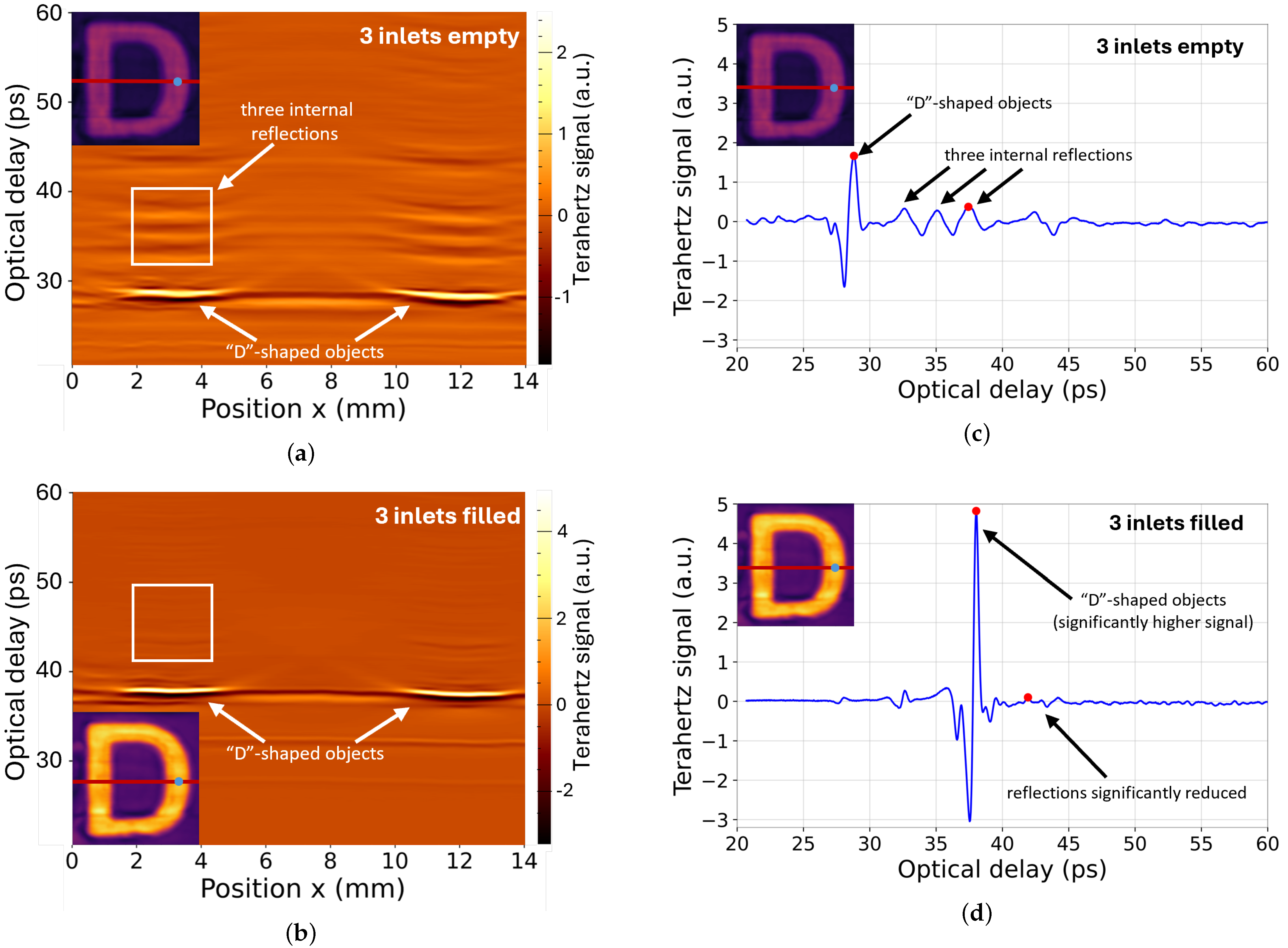
As an additional investigation of the presented results, THz TDS reflection measurements were conducted for the multilayer structure with three inlets that were empty and three inlets filled with oil. Thus, horizontal-depth B-slice views of the signal intensity distribution within the structure were generated to provide further insights. In Figure 6a,b, the obtained-depth B-slice cross-sections are presented, while Figure 6c,d depicts the recorded signal intensity as a function of optical delay. The horizontal B-slice cross-sections were taken at the midpoint of the imaged object, with their region marked by a red transverse line in the inset. In Figure 6a,b, the white square indicates the region from which the signal fluctuations were evaluated using the mean gradient magnitude within the selected area. Meanwhile, the recorded signal as a function of optical delay, shown in Figure 6c,d, was extracted for a point passing through the imaged “D”-shaped object, marked by a green dot in the inset. In Figure 6c,d, the red dots indicate the peaks of the signal reflected from the object, as well as the highest undesired signal level registered due to internal reflections within the multilayer structure.
In both B-slice cross-sections shown in Figure 6a,b, the reflection from the “D”-shaped object is visible and marked in the images. For the empty multilayer structure (Figure 6a), after the main reflection is registered, a secondary signal caused by internal reflections within the structure reaches the detector with a delay. This results in three main signal distortions corresponding to the three air gaps, as well as the following distortions. In contrast, when the multilayer structure is filled with synthetic oil 18 (Figure 6b), the reflected signal from the “D”-shaped object is significantly stronger, while the secondary reflections and the following distortions are nearly eliminated. This is further confirmed by the mean gradient magnitude evaluated within the region marked by the white square, which amounts to 6.29 for the empty structure and 0.88 for the structure with three filled inlets. Higher gradient values indicate increased signal distortion, which in this case corresponds to signal losses associated with undesired enhancements caused by interference originating from internal reflections.
This behavior is further illustrated by the local time-domain analysis of the recorded signal, shown in Figure 6c,d. For the structure with empty inlets (Figure 6c), the signal corresponding to the main reflection reaches a level of 1.67 a.u., followed by three secondary reflections, with the highest undesired reflection attaining 0.37 a.u. at the detector. The ratio between the main reflection and this secondary peak is 4.45. However, when the gaps are filled with oil (Figure 6d), the signal from the “D”-shaped object is significantly enhanced, reaching a main reflection level of 4.82 a.u., while the strongest secondary reflection is reduced to 0.10 a.u. The ratio between these signals is equal to 47.59.

4. Discussion

Recent studies have increasingly focused on identifying suitable fabrication methods and well-performing materials for advanced optical structures operating in the THz range [35,36,37]. Achieving high-resolution fabrication of structures with subwavelength features [38], designed using iterative algorithms [39] or neural network methods [19,20], represents a crucial step in the development of passive THz optics. Among the available fabrication methods, FDM is currently the most widely employed, largely because it enables the use of COC material, which combines high transparency in the THz range with excellent mechanical stability [16,17].
In the literature, extensive research has been devoted to investigating the optical properties of polymers [14,36,37]. However, significantly fewer studies have explored the optical properties of alternative materials that could serve as refractive-index-matching fillers for integration with 3D-printed THz optics. In this study, the authors present an investigation of the optical properties of various oils using THz TDS. Based on these measurements, the authors identified a synthetic oil that exhibits remarkable refractive-index-matching with COC. Compared to other casting or embedding materials reported in the literature, such as waxes and paraffins, or even unconventional substances such as chocolate [15], oils provide unique benefits arising from their liquid nature. The proper application of oils with well-matched refractive indices enables a substantial reduction of Fresnel reflection losses in THz optical systems, thereby mitigating signal attenuation and suppressing unwanted interference effects while also facilitating optical coupling between components and filling delaminations in THz optical components. Investigating the optical properties of unconventional materials, therefore, represents an important aspect of advancing THz optics.
An important aspect is the proper application of refractive-index-matching oils when scaling to larger and more complex THz systems. It is essential to ensure that the filler remains confined to the designated region of the object without leakage, as uncontrolled spreading could limit the reliability and efficiency of the approach. Moreover, it should be noted that oil-based fillers are not suitable for high-power radiation sources, as heating effects may change their optical and mechanical properties and thus reduce their performance. Addressing such challenges would require further dedicated studies to develop alternative solutions or modified fillers specifically tailored for high-power source applications.
Another research direction aimed at mitigating unwanted reflections in THz optical systems involves the application of anti-reflection coatings, such as polymer films [40,41] or subwavelength micropyramids [42]. However, these studies typically address elements fabricated from materials with significantly higher refractive indices than COC. Nevertheless, it could be stated that in some cases a uniform oil coating can act as an effective anti-reflection coating layer for such components, providing a simple and convenient solution. Reflection suppression remains essential for reducing both transmission losses and unwanted interference effects in complex THz optical systems.
In addition, this study demonstrates the use of THz TDS depth scans (B-slice cross-sectional views) for characterizing multilayer structures. These measurements allow for evaluating the THz wave propagation within spatially inhomogeneous volumes, thus providing valuable insights into the signal distribution of the internal structure. However, it should be emphasized that the objects investigated in this study were designed to exhibit periodic and relatively simple refractive-index profiles. For more complex or irregularly structured objects, advanced THz tomographic approaches will be required. Such methods are expected to play a key role in future studies and constitute a promising direction for further exploration in this field [43].

5. Conclusions

This study presents the results of optical properties measurements for 20 different oils of plant, mineral, and synthetic origin, conducted using THz TDS in transmission mode within a dry air chamber. The results identified mineral and synthetic oils with exceptionally low absorption coefficients in the THz radiation range. Additionally, the refractive index of selected oils was matched to the optical properties of the specified polymer materials, facilitating the prototyping using FDM technology of highly transparent passive optical components in the THz range. This enables the selection of appropriate oils for combining optical components in complex THz systems, significantly reducing unwanted Fresnel reflections and signal losses within the system. Consequently, this leads to a notable improvement in the efficiency of THz optical setups. Moreover, the proposed oils are superior materials for filling delaminations in optical elements, which can greatly enhance their performance.
Further studies were conducted on multilayer structures with three air-gap inlets. These inlets were sequentially filled with the selected synthetic oil. The multilayer structures represented the connection of successive THz optical elements in an experimental setup. The THz TDS measurements allowed for the evaluation of parasitic internal Fresnel reflections and corresponding signal losses, as well as enabled the determination of recorded signal gain in the reflection mode imaging as the inlets were filled with oil. The results demonstrated a 2.33 times increase in the recorded signal when the proposed oil was applied, highlighting the potential of this solution.
Thus, the selection of a suitable filler, such as the recommended oils, is critical for improving the efficiency of optical systems that require the integration of multiple elements to maintain complex functionality.

Author Contributions

Conceptualization, M.K. and A.S.; methodology, M.K. and A.S.; software, M.K.; validation, M.K.; formal analysis, M.K.; investigation, M.K. and M.S.; resources, A.S. and W.K.; data curation, M.K. and A.N.; writing—original draft preparation, M.K.; writing—review and editing, A.N., M.S., W.K. and A.S.; visualization, M.K.; supervision, A.S. and W.K.; project administration, A.S. and W.K.; funding acquisition, A.S. and W.K. All authors have read and agreed to the published version of the manuscript.

Funding

Reported research was realized within the confines of the project “NSMET National Network of Coordinate Metrology” financed from the European Regional Development Fund under Measure 4.2 of Smart Growth Operational Program 2014-2020, contract no. POIR.04.02.00-00-D012/20-00.

Data Availability Statement

The original data presented in the study are openly available in the Knowledge Base of Warsaw University of Technology at http://dx.doi.org/10.71724/1e0g-d765, reference number WUT86bee25efc60459b8e8b76f33dc02ece (accessed on 7 April 2025).

Acknowledgments

The authors would like to thank Patricio Andres Espinoza Guevara for his assistance in conducting the experimental investigations presented in this study, carried out as part of her MSc thesis under the supervision of A. Siemion.

Conflicts of Interest

The authors declare no conflicts of interest.

Abbreviations

The following abbreviations are used in this manuscript:
ABSacrylonitrile butadiene styrene
COCcyclic olefin copolymer
DLPdigital light processing
FDMfused deposition modeling
HDPEhigh-density polyethylene
HIPShigh-impact polystyrene
IMPATTImpact Ionization Avalanche Transit-Time Diode
LLDPElinear low-density polyethylen
PA12polyamide 12
PETGpolyethylene terephthalate glycol-modified
PPpolypropylene
PTFEpolytetrafluoroethylene
RTDResonant Tunnelling Diode
SBCstyrene-butadiene copolymer
SLSselective laser sintering
THzterahertz
THz TDSterahertz time-domain spectroscopy
TPEthermoplastic elastomer
VDIVirginia Diodes Inc.
VP/VAvinylpyrrolidone/vinyl acetate copolymers

References

  1. Markelz, A.G.; Mittleman, D.M. Perspective on terahertz applications in bioscience and biotechnology. ACS Photonics 2022, 9, 1117–1126. [Google Scholar] [CrossRef]
  2. Yan, Z.; Zhu, L.G.; Meng, K.; Huang, W.; Shi, Q. THz medical imaging: From in vitro to in vivo. Trends Biotechnol. 2022, 40, 816–830. [Google Scholar] [CrossRef] [PubMed]
  3. Chernomyrdin, N.V.; Musina, G.R.; Nikitin, P.V.; Dolganova, I.N.; Kucheryavenko, A.S.; Alekseeva, A.I.; Wang, Y.; Xu, D.; Shi, Q.; Tuchin, V.V.; et al. Terahertz technology in intraoperative neurodiagnostics: A review. Opto-Electron. Adv. 2023, 6, 220071. [Google Scholar] [CrossRef]
  4. Shafie, A.; Yang, N.; Han, C.; Jornet, J.M.; Juntti, M.; Kürner, T. Terahertz communications for 6G and beyond wireless networks: Challenges, key advancements, and opportunities. IEEE Netw. 2023, 37, 162–169. [Google Scholar] [CrossRef]
  5. Jiang, W.; Han, B.; Habibi, M.A.; Schotten, H.D. The road towards 6G: A comprehensive survey. IEEE Open J. Commun. Soc. 2021, 2, 334–366. [Google Scholar] [CrossRef]
  6. Knipper, R.; Brahm, A.; Heinz, E.; May, T.; Notni, G.; Meyer, H.G.; Tunnermann, A.; Popp, J. THz absorption in fabric and its impact on body scanning for security application. IEEE Trans. Terahertz Sci. Technol. 2015, 5, 999–1004. [Google Scholar] [CrossRef]
  7. Tao, Y.H.; Fitzgerald, A.J.; Wallace, V.P. Non-contact, non-destructive testing in various industrial sectors with terahertz technology. Sensors 2020, 20, 712. [Google Scholar] [CrossRef]
  8. Headland, D.; Monnai, Y.; Abbott, D.; Fumeaux, C.; Withayachumnankul, W. Tutorial: Terahertz beamforming, from concepts to realizations. APL Photonics 2018, 3, 051101. [Google Scholar] [CrossRef]
  9. Khonina, S.N.; Kazanskiy, N.L.; Skidanov, R.V.; Butt, M.A. Advancements and applications of diffractive optical elements in contemporary optics: A comprehensive overview. Adv. Mater. Technol. 2025, 10, 2401028. [Google Scholar] [CrossRef]
  10. He, J.; Dong, T.; Chi, B.; Zhang, Y. Metasurfaces for terahertz wavefront modulation: A review. J. Infrared Millim. Terahertz Waves 2020, 41, 607–631. [Google Scholar] [CrossRef]
  11. Sun, J.; Hu, F. Three-dimensional printing technologies for terahertz applications: A review. Int. J. RF Microw. Comput-Aid. Eng. 2020, 30, e21983. [Google Scholar] [CrossRef]
  12. Wu, G.B.; Chen, J.; Yang, C.; Chan, K.F.; Chen, M.K.; Tsai, D.P.; Chan, C.H. 3-D-printed terahertz metalenses for next-generation communication and imaging applications. Proc. IEEE Inst. Electr. Electron. Eng. 2024, 112, 1033–1050. [Google Scholar] [CrossRef]
  13. Komorowski, P.; Kaluza, M.; Surma, M.; Siemion, A. 3D printed diffractive lenses operating at 1 THz. Lith. J. Phys. 2023, 63, 122–130. [Google Scholar] [CrossRef]
  14. Squires, A.D.; Lewis, R.A. Feasibility and characterization of common and exotic filaments for use in 3D printed terahertz devices. J. Infrared Millim. Terahertz Waves 2018, 39, 614–635. [Google Scholar] [CrossRef]
  15. Kałuża, M.; Komorowski, P.; Walczakowski, M.; Nieradka, A.; Siemion, A. Optical Properties of Materials in the Terahertz Spectral Range; Knowledge Base of Warsaw University of Technology: Warszawa, Poland, 2025. [Google Scholar] [CrossRef]
  16. Kaluza, M.; Walczakowski, M.; Siemion, A. Exploring the impact of 3D printing parameters on the THz optical characteristics of COC material. Materials 2024, 17, 5104. [Google Scholar] [CrossRef]
  17. Busch, S.F.; Weidenbach, M.; Balzer, J.C.; Koch, M. THz optics 3D printed with TOPAS. J. Infrared Millim. Terahertz Waves 2016, 37, 303–307. [Google Scholar] [CrossRef]
  18. Rogalin, V.E.; Kaplunov, I.A.; Kropotov, G.I. Optical materials for the THz range. Opt. Spectrosc. 2018, 125, 1053–1064. [Google Scholar] [CrossRef]
  19. Luo, Y.; Mengu, D.; Yardimci, N.T.; Rivenson, Y.; Veli, M.; Jarrahi, M.; Ozcan, A. Design of task-specific optical systems using broadband diffractive neural networks. Light Sci. Appl. 2019, 8, 112. [Google Scholar] [CrossRef] [PubMed]
  20. Liao, D.; Chan, K.F.; Chan, C.H.; Zhang, Q.; Wang, H. All-optical diffractive neural networked terahertz hologram. Opt. Lett. 2020, 45, 2906–2909. [Google Scholar] [CrossRef] [PubMed]
  21. Kaluza, M.; Komorowski, P.; Nieradka, A.; Zagrajek, P.; Siemion, A. Implementing terahertz spatial multiplexing and frequency demultiplexing systems using diffractive optical elements for 6G telecommunications applications. IEEE Trans. Microw. Theory Tech. 2025, 73, 6037–6048. [Google Scholar] [CrossRef]
  22. Mehdi, I.; Siles, J.V.; Lee, C.; Schlecht, E. THz diode technology: Status, prospects, and applications. Proc. IEEE Inst. Electr. Electron. Eng. 2017, 105, 990–1007. [Google Scholar] [CrossRef]
  23. Kaluza, M.; Nieradka, A.; Komorowski, P.; Siemion, A. Challenges and limitations of terahertz phase imaging method. Photonics Lett. Pol. 2024, 16, 82–86. [Google Scholar] [CrossRef]
  24. Ge, H.; Sun, Z.; Jiang, Y.; Wu, X.; Jia, Z.; Cui, G.; Zhang, Y. Recent advances in THz detection of water. Int. J. Mol. Sci. 2023, 24, 10936. [Google Scholar] [CrossRef]
  25. Wang, T.; Klarskov, P.; Jepsen, P.U. Ultrabroadband THz time-domain spectroscopy of a free-flowing water film. IEEE Trans. Terahertz Sci. Technol. 2014, 4, 425–431. [Google Scholar] [CrossRef]
  26. Kałuża, M.; Nieradka, A.; Surma, M.J.; Krauze, W.; Siemion, A. Terahertz Optical Properties of Oils for Signal Loss Reduction in Multilayer Structures; Knowledge Base of Warsaw University of Technology: Warszawa, Poland, 2025. [Google Scholar] [CrossRef]
  27. Mavrona, E.; Appugliese, F.; Andberger, J.; Keller, J.; Franckié, M.; Scalari, G.; Faist, J. Terahertz refractive index matching solution. Opt. Express 2019, 27, 14536–14544. [Google Scholar] [CrossRef]
  28. Hu, Y.; Guo, L.; Wang, X.; Zhang, X.C. THz time-domain spectroscopy on plant oils and animal fats. In Proceedings of the Infrared Components and Their Applications, Beijing, China, 8–11 November 2004; Gong, H., Cai, Y., Chatard, J.P., Eds.; SPIE: Bellingham, WA, USA, 2005. [Google Scholar] [CrossRef]
  29. Neu, J.; Schmuttenmaer, C.A. Tutorial: An introduction to terahertz time domain spectroscopy (THz-TDS). J. Appl. Phys. 2018, 124, 231101. [Google Scholar] [CrossRef]
  30. Coutaz, J.L.; Bernier, M.; Garet, F.; Joly, S.; Miyake, Y.; Minamide, H.; Lheurette, E.; Lippens, D. Terahertz time-domain spectroscopy of absorbing materials and of metamaterials. Terahertz Sci. Technol. 2014, 7, 53–69. [Google Scholar] [CrossRef]
  31. Zeranska-Chudek, K.; Siemion, A.; Palka, N.; Mdarhri, A.; Elaboudi, I.; Brosseau, C.; Zdrojek, M. Terahertz shielding properties of carbon black based polymer nanocomposites. Materials 2021, 14, 835. [Google Scholar] [CrossRef]
  32. Li, Z.; Cheng, S.; Zhang, H.; Yang, W.; Yi, Z.; Yi, Y.; Wang, J.; Ahmad, S.; Raza, R. Ultrathin broadband terahertz metamaterial based on single-layer nested patterned graphene. Phys. Lett. A 2025, 534, 130262. [Google Scholar] [CrossRef]
  33. Xin, X.; Altan, H.; Saint, A.; Matten, D.; Alfano, R.R. Terahertz absorption spectrum of para and ortho water vapors at different humidities at room temperature. J. Appl. Phys. 2006, 100, 094905. [Google Scholar] [CrossRef]
  34. Slocum, D.M.; Slingerland, E.J.; Giles, R.H.; Goyette, T.M. Atmospheric absorption of terahertz radiation and water vapor continuum effects. J. Quant. Spectrosc. Radiat. Transf. 2013, 127, 49–63. [Google Scholar] [CrossRef]
  35. Castro-Camus, E.; Koch, M.; Hernandez-Serrano, A.I. Additive manufacture of photonic components for the terahertz band. J. Appl. Phys. 2020, 127, 210901. [Google Scholar] [CrossRef]
  36. Brodie, C.H.; Spotts, I.; Reguigui, H.; Leclerc, C.A.; Mitchell, M.E.; Holzman, J.F.; Collier, C.M. Comprehensive study of 3D printing materials over the terahertz regime: Absorption coefficient and refractive index characterizations. Opt. Mater. Express 2022, 12, 3379–3402. [Google Scholar] [CrossRef]
  37. Duangrit, N.; Hong, B.; Burnett, A.D.; Akkaraekthalin, P.; Robertson, I.D.; Somjit, N. Terahertz dielectric property characterization of photopolymers for additive manufacturing. IEEE Access 2019, 7, 12339–12347. [Google Scholar] [CrossRef]
  38. Wang, Y.; Zhang, X.; Wang, Y.; Liu, Y.; Li, J.; Chen, X.; Cui, Z.; Burokur, S.N.; Zhang, J.; Zhao, X.; et al. Recent advances in metasurfaces: From THz biosensing to microwave wireless communications. Research 2025, 8, 0820. [Google Scholar] [CrossRef] [PubMed]
  39. Kaluza, M.; Komorowski, P.; Surma, M.; Nieradka, A.; Zagrajek, P.; Siemion, A. Advanced diffractive optical elements implementing multiple-input spatial multiplexing of terahertz radiation. Opt. Lasers Eng. 2025, 184, 108606. [Google Scholar] [CrossRef]
  40. Ahmed, A.; Braconnier, A.; Gibbs, J.; Burgess, J.A.J. Terahertz antireflection coatings employing off-the-shelf adhesive tapes. Appl. Opt. 2022, 61, 6316–6321. [Google Scholar] [CrossRef]
  41. Shevchik-Shekera, A.; Sizov, F.; Golenkov, O.; Lysiuk, I.; Petriakov, V.; Kovbasa, M. Silicon lenses with HDPE anti-reflection coatings for low THz frequency range. Semicond. Phys. Quantum Electron. Optoelectron. 2023, 26, 59–67. [Google Scholar] [CrossRef]
  42. Han, P.; Chen, Y.; Zhang, X.C. Application of silicon micropyramid structures for antireflection of terahertz waves. IEEE J. Sel. Top. Quantum Electron. 2010, 16, 338–343. [Google Scholar] [CrossRef]
  43. Guillet, J.P.; Recur, B.; Frederique, L.; Bousquet, B.; Canioni, L.; Manek-Hönninger, I.; Desbarats, P.; Mounaix, P. Review of terahertz tomography techniques. J. Infrared Millim. Terahertz Waves 2014, 35, 382–411. [Google Scholar] [CrossRef]
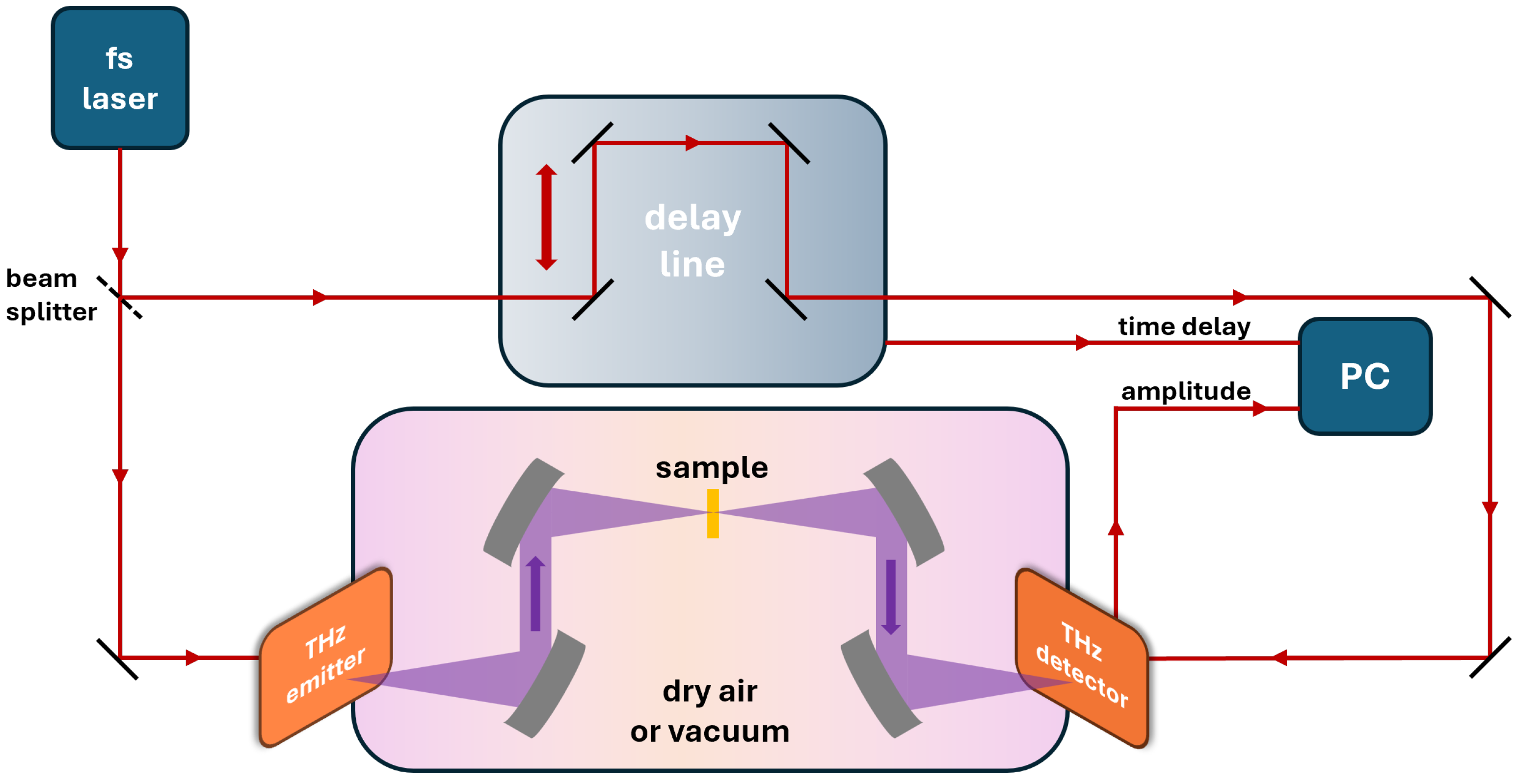
Figure 1. A schematic diagram of the THz TDS setup operating in transmission mode.
Applsci 15 11167 g001
Figure 2. The photographs of 3D-printed structures manufactured from cyclic olefin copolymer (COC) using fused deposition modeling (FDM) technology: (a) an empty cuvette; (b,c) front and back view of a cuvette filled with plant oil (oil 1 in Table 1) mounted in a holder for THz TDS; (d,e) empty and filled with oil (oil 18 in Table 1) multilayered structure consisting of alternating walls and air/oil gaps between them; (f) the multilayered structure with mounted “D letter” object for THz TDS imaging measurements in reflection mode.
Applsci 15 11167 g002
Figure 3. The optical properties of twenty different oils were investigated using terahertz time-domain spectroscopy (THz TDS) in transmission mode within a chamber filled with dry air. (a) Absorption coefficient in the frequency range of 0.1–1.5 THz. (b) Refractive index in the frequency range of 0.1–1.5 THz. (c,d) Enlarged views of the absorption coefficient and refractive index, respectively, in the narrower range of 0.5–0.7 THz for plant and fish oils, highlighting the differences within this group. (e,f) Enlarged views of the absorption coefficient and refractive index, respectively, in the range of 0.5–0.7 THz for mineral and synthetic oils.
Applsci 15 11167 g003aApplsci 15 11167 g003b
Figure 4. The optical properties of the multilayer structure characterized for the case of three empty inlets and subsequently for configurations with successive inlets filled with the synthetic oil (oil 18 in Table 1): (a) the absorption coefficient in the THz frequency domain; (b) the refractive index in the THz frequency domain.
Applsci 15 11167 g004
Figure 5. The results of terahertz time-domain spectroscopy (THz TDS) scans in the reflection mode for the multilayer structure with mounted highly reflective “D”-shaped object on the back surface of the structure. The presented data corresponds to the multilayer structure with (a) three empty inlets; (b) one inlet filled with the synthetic oil (oil 18 in Table 1); (c) two inlets filled with the synthetic oil; and (d) all three inlets filled with the synthetic oil. Each scan highlights two areas of interest: the region marked in green represents the radiation reflected from the “D”-shaped object, while the region marked in red corresponds to the area where the recorded signal did not interact with the object.
Applsci 15 11167 g005
Figure 6. The analysis of the results of terahertz time-domain spectroscopy (THz TDS) scans in the reflection mode for the multilayer structure with a highly reflective “D”-shaped object mounted on the back surface. The presented data corresponds to the multilayer structure with (a) three empty inlets in the B-slice cross-section view; (b) three inlets filled with the synthetic oil 18 in the B-slice cross-section view; (c) three empty inlets in the time-domain THz signal distribution; and (d) three inlets filled with the synthetic oil 18 in the time-domain THz signal distribution. The areas of the B-slice cross-sections are marked in red, while the locations of the registered THz time-domain signal are marked in green in the inset images.
Applsci 15 11167 g006
Table 1. Detailed information on the oils, whose optical properties were investigated using terahertz time-domain spectroscopy (THz TDS).
ID abTypeBaseBrand Name
oil 1extra virgin olive oil (1)plant oilLugliO
oil 2extra virgin olive oil (2)plant oilKalamata Gold
oil 3rapeseed oil (1)plant oilVita D’or
oil 4rapeseed oil (2)plant oilKujawski
oil 5rapeseed oil (3)plant oilBielmar
oil 6sunflower oilplant oilClever
oil 7milk thistle seed oilplant oilunavailable
oil 8pumpkin seed oilplant oilOleofarm
oil 9hazelnut oilplant oilOleofarm
oil 10toasted sesame oilplant oilOh Aik Guan
oil 11rice bran oilplant oilOlitalia
oil 12hypoallergenic plant oilplant oilBaltazar
oil 13fish oil (Omega 3 TOTAL)fish oilNorsan
oil 14immersion oil (1)plant oilMerck
oil 15immersion oil (2)not disclosedBresser
oil 16immersion oil (3)synthetic oilDelta Optical
oil 17synthetic engine oil (1)synthetic oilTotal Quartz INEO ECS 5W-30
oil 18synthetic engine oil (2)fully synthetic oilMobil Super 3000 5W-40
oil 19lubricant (WD-40)light mineral oilWD-40
oil 20mineral oil (baby oil)mineral oilJohnson’s
a Plant and fish oils (green rows) showed similar average THz attenuation. b Mineral and synthetic oils (blue rows) showed very low THz attenuation.
Table 2. Quantitative analysis of terahertz time-domain spectroscopy (THz TDS) reflection scans for two regions of interest (green and red in Figure 5): background intensity I background , object intensity I object , and signal gain G (with its minimum and maximum bounds) for successive cases of filled inlets.
Multilayer Structure State I background [ a . u . ] I object [ a . u . ] G aGminGmax
three inlets empty1.063.39– I object ( empty ) 1.000.861.16
one inlet filled1.784.871.441.271.63
two inlets filled2.206.471.911.692.17
three inlets filled2.137.882.332.072.62
a Signal gain is defined as G = I object ( filled ) / I object ( empty ) . The shaded (purple) column highlights the average enhancement achieved with oil application, while G min and G max denote its lower and upper bounds calculated according to Equations (4) and (5).
Disclaimer/Publisher’s Note: The statements, opinions and data contained in all publications are solely those of the individual author(s) and contributor(s) and not of MDPI and/or the editor(s). MDPI and/or the editor(s) disclaim responsibility for any injury to people or property resulting from any ideas, methods, instructions or products referred to in the content.