Article

Evaluation of Plasma Dynamic Parameters of a Multi-Layer MIF Target Under Exposure to External Broadband Radiation

by
Victor V. Kuzenov
,
Sergei V. Ryzhkov
* and
Artem G. Polyanskiy
Power Engineering Faculty, Bauman Moscow State Technical University, Moscow 105005, Russia
*
Author to whom correspondence should be addressed.
Appl. Sci. 2025, 15(20), 11155; https://doi.org/10.3390/app152011155
Submission received: 23 September 2025 / Revised: 7 October 2025 / Accepted: 16 October 2025 / Published: 17 October 2025
(This article belongs to the Special Issue Advances in Fusion Engineering and Design Volume II)

Abstract

This work presents a numerical investigation into broadband radiation effects (with energy flux densities q < 1014 W/cm2) on a magneto–inertial fusion (MIF) target. The calculation results demonstrate the impact of intense energy fluxes on a multi-layer cylindrical target that provides more uniform and homogeneous compression. All principal dynamic parameters (plasma dynamics and radiative) of the compressed target plasma have been determined. The work performed allows us to draw the following initial conclusion: it is advisable to create compact neutron generators based on the MIF scheme on a multi-layer version of the target (made of “heavy” chemical elements).

1. Introduction

Typically, the MIF scheme [1,2,3,4] achieves compression and heating of the plasma formation by high-speed plasma jets or high-power laser radiation. In this paper, the effect of external broadband radiation on a cylindrical target is studied numerically.
The pulsed radiation source (a Hohlraum design variant) comprises conical cavities embedded within a high-density solid material. Each conical cavity (exposed to external laser radiation) contains gaseous deuterium or its mixture with tritium. The D-T gas is confined within either a flat thin-walled shell or a convex membrane. When interacting with concentrated energy flux (laser beams), the shell implodes into the cavity at supersonic velocity, compressing and heating the D-T fuel. The plasma compression in the conical section of the radiation source can generate intense axis-aligned broadband radiation ( q = σ T 4 ~ 1016–1020 W/cm2). In this configuration, the initial laser radiation (qL ~ 1014 W/cm2) may be amplified by up to 100 times (or more) through thermonuclear burning of the D-T mixture within the conical cavity.
The process of interaction between external broadband radiation and the target can be evolutionarily described as follows: After the initial heating of the target wall material by a strong shock wave (generated by heating the target with external broadband radiation), it accelerates and moves towards the center of symmetry of the target. When the center of symmetry of the fuel-containing target layers is reached, they accumulate (up to the stage of nuclear reactions). The cumulation along the system’s geometric axis compresses the plasma to the stage of nuclear reactions, where the reaction probability is proportional to exp K Z 1 Z 2 / E ; here, Z1, Z2 are the proton numbers of the interacting nuclei, E is their relative approach energy, and K is a plasma-specific scaling factor in the target.
Addressing this complex scientific–technical challenge requires the concurrent refinement of both plasma–physical models for targets and numerical methods to obtain its solution. Notably, such mathematical models may also enable the evaluation of physico–technical parameters for compact generators with practical applications, particularly those capable of producing intense, long-lifetime sources of high-energy particles (ions, neutrons).
The following is a brief description of the mathematical model used in the work; a variant of the author’s numerical methodology is indicated, and in Section 3 some of the results obtained in the work are analyzed. The conclusion is given at the end of the paper.

2. Mathematical Model and Computational Algorithm

In its full formulation—a multidimensional, multivelocity, multitemperature problem accounting for numerous possible physicochemical processes—this represents an exceptionally challenging computational task, even for modern high-performance computing systems.
However, the problem under consideration can be investigated using magnetohydrodynamic (MHD) models. This approach requires several simplifying assumptions, of which we highlight the following key ones:
  • We will assume that plasma formation (monatomic plasma composition) consists of dissociated neutral and ionized gas. The mathematical description of the dynamics of such a plasma formation is based on a multi-liquid (single-velocity), high-temperature, chemically non-reactive continuous plasma medium.
  • The calculation of dynamic processes (absorption and scattering) related to the solution of the Vlasov (or Fokker–Planck) kinetic equation for relativistic “suprathermal” electrons in a magnetic field is not considered.
  • At the initial time, the plasma formation and the surrounding medium can be differentiated by specifying distinct thermodynamic parameters, as well as the degree of ionization α = ne/n, where ne and n are the electron and heavy particle concentrations, respectively.
Assuming that the energy input by broadband radiation is cylindrically symmetrical and the wall of the multi-layer cylindrical target is thin, we will proceed with a one-dimensional mathematical model describing compression and energy release processes in the target. This mathematical model is based on the equations of radiation plasma dynamics, which take into account a self-sustaining thermonuclear fusion reaction. The governing equations are formulated in a spherically symmetric coordinate system and include the following:
ρ / t + d i v ρ u   = 0 ,
ρ u / t + d i v ρ u 2 + P   = f r ,   f r = 1 c j × H r
ρ E / t + d i v ρ E u + P u + q   = q r + Q F u s e
ρ e e / t + d i v ρ e e u + P e u + q + q e = q r Q e i + Q F u s e
q r = j r E r + j z E z q = q e + q i + q , P = P e + P i
where the index v = 1 , 2 , 3 corresponds to cases of planar, axial, and spherical symmetry, and qterm is the density of the external broadband radiation flux directed perpendicular to the generatrix of the multi-layer cylindrical target.
The fictitious impurity method is used to determine the spatiotemporal position of the contact boundary separating the plasma of the D–T mixture from the plasma of metals (Al, Au) or the environment. To do this, several additional equations are introduced into the system of the above equations ρ g 0 , 1 of the form ρ g / t + u ρ g / r = 0 . Knowing ρ g , it is possible to determine the position of the contact boundary Γ(t) = { ξ : ρ g ξ , t = 0 }, which divides the entire computational domain into several regions, each of which corresponds to a D-T mixture, metal (Al) plasma, or the environment, depending on the sign of the function ρ g .
Broadband radiation is calculated using a multigroup diffusion approximation [5,6]:
d i v ( q v ) + χ v c U v = χ v 4 σ T 4 ,   c 3 U v + χ v q v = 0 .
If the electron and ion distribution functions are Maxwellian, the energy transferred per unit time per unit volume from electrons to ions can be calculated by the formula
Q e i = k = 1 s f k 2 m e M k 3 2 k T e T i , k v e i , k n e .
Here, v e i , k is the average frequency of electron–ion collisions with momentum transfer, given by the following [7]:
v e i , k = 4 2 π   n k Z i , k 2 e 4 ln Λ e i 3 m e 1 / 2 k T e 3 / 2 ,   τ e i = 1 v e i 1 + θ 8 ,
where E F = h 2 2 m e 3 π 2 n e 2 3 is the Fermi degenerate energy, and θ = exp E F k T e is the plasma degeneracy parameter that describes, in particular, the limiting cases of classical ( θ 1 ) and fully degenerate ( θ = 0 ) plasma.
The developed numerical methodology has been verified through solutions to a series of test (model) problems [6,7,8,9,10,11,12,13,14].

3. Calculation Results

The computational domain and MIF target (Figure 1) consist of a central part and two coaxial layers (Al and Au). The computational domain has an outer radius 0.3 cm.
Derivatives of the species T / z , ln n e / z are determined along the forming multi-layer cylindrical target [15].
Then, the spatial region r f n u c l and the velocity V f n u c l of the thermonuclear reaction (propagation of the “thermal wave”) are estimated as r f n u c l = χ τ n u c l , V f n u c l = 1 2 χ / τ n u c l . Here, τ n u c l is the characteristic time of thermonuclear burning, τ n u c l = M i ρ 1 V σ , where ρ is the current charge density, Mi is the mass of the ion participating in the thermonuclear reaction, V is the relative velocity of interacting nuclei participating in the thermonuclear reaction, and σ is the cross-section of the thermonuclear reaction.
The propagation velocity of the “photodetonation” wave VD can be found from the relation V D = 2 γ 2 1 q ρ 0 1 / 3 , where ρ0 is the medium density ahead of the photodetonation wave front [14]. Assuming equality ( q P f r f n u c l –ignition by a “light-detonation” wave) of energy releases in the “light-detonation” wave q and in the region of the self-sustaining thermonuclear reaction P f r f n u c l , one can obtain the following estimate for the velocity of the thermonuclear reaction propagating in the “photodetonation” regime: V D n u c l = 2 γ 2 1 P f r f n u c l ρ 0 1 / 3 , where P f = n a n b σ V a , b E f is the fusion power per unit volume, n a n b are the volume concentrations of reacting particles of the variety a, b; σ V a , b is the activity, the product of the reaction cross-section and the average particle velocity in the Maxwell distribution; and Ef is the energy of the thermonuclear reaction.
The expression for the specific power of bremsstrahlung radiation [6] is Q = 1.5 × 10 27 n e n i Z 2 T e [erg/(s·cm3)], where Z is the charge number of the ion of the element; n e , n i is the electron and ion concentration, cm3; and Te is the electron plasma temperature, K. It follows from this ratio (all other things being equal) that the power Q A u of the “braking” radiation at the contact boundary (Figure 2 and Figure 3) from Au to Al is approximately 32 times greater, and from Al to D-T by 42 times.
The process of compression (relative to time t) of the target by a system of pulsed broadband radiators (a variant of the Holraum design) can be described as having several spatial structural phases [15] (the main phases are the “collapse”, “re-reflection”, and “expansion” of the compressed and heated plasma).
Using the graphical dependencies shown in Figure 1, Figure 2, Figure 3 and Figure 4, the paper describes the most interesting phases of “collapse” (Figure 1 and Figure 2) and “re-reflections” (Figure 3 and Figure 4).
The initial phase lasts for a time interval of 0 ≤ t ≤ 0.78 ns (multi-layer case of Al–Au) and 0 ≤ t ≤ 0.4 ns (single-layer case: Al).
The “collapse” phase (Figure 1 and Figure 2) depends on the number of layers and target material, and lasts for the following time intervals, approximately: 0.78 ≤ t ≤ 1.03 ns for the multi-layer case (Figure 1; Al–Au) and 0.4 ≤ t ≤ 0.61 ns for the single-layer case (Figure 2; Al only). In the multi-layer case (note that the atomic mass of aluminum is 2.7 g/cm3, and for gold it is 19.25 g/cm3), a later convergence of the spatial region occupied by the “thermal wave” (thermal wave velocity approximately corresponds to the electron temperature front velocity in the multi-layer target) with the system’s geometric symmetry axis is observed. In Figure 1, at distance r = 0.04 cm (from the symmetry axis), a shock wave is observed, behind the front of which there is a weak (T-Teq~0.6 million K) temperature stratification Te > Teq. Note (Figure 2) that, in the single-layer case, the temperature stratification Te, Teq is more significant (~40 million K).
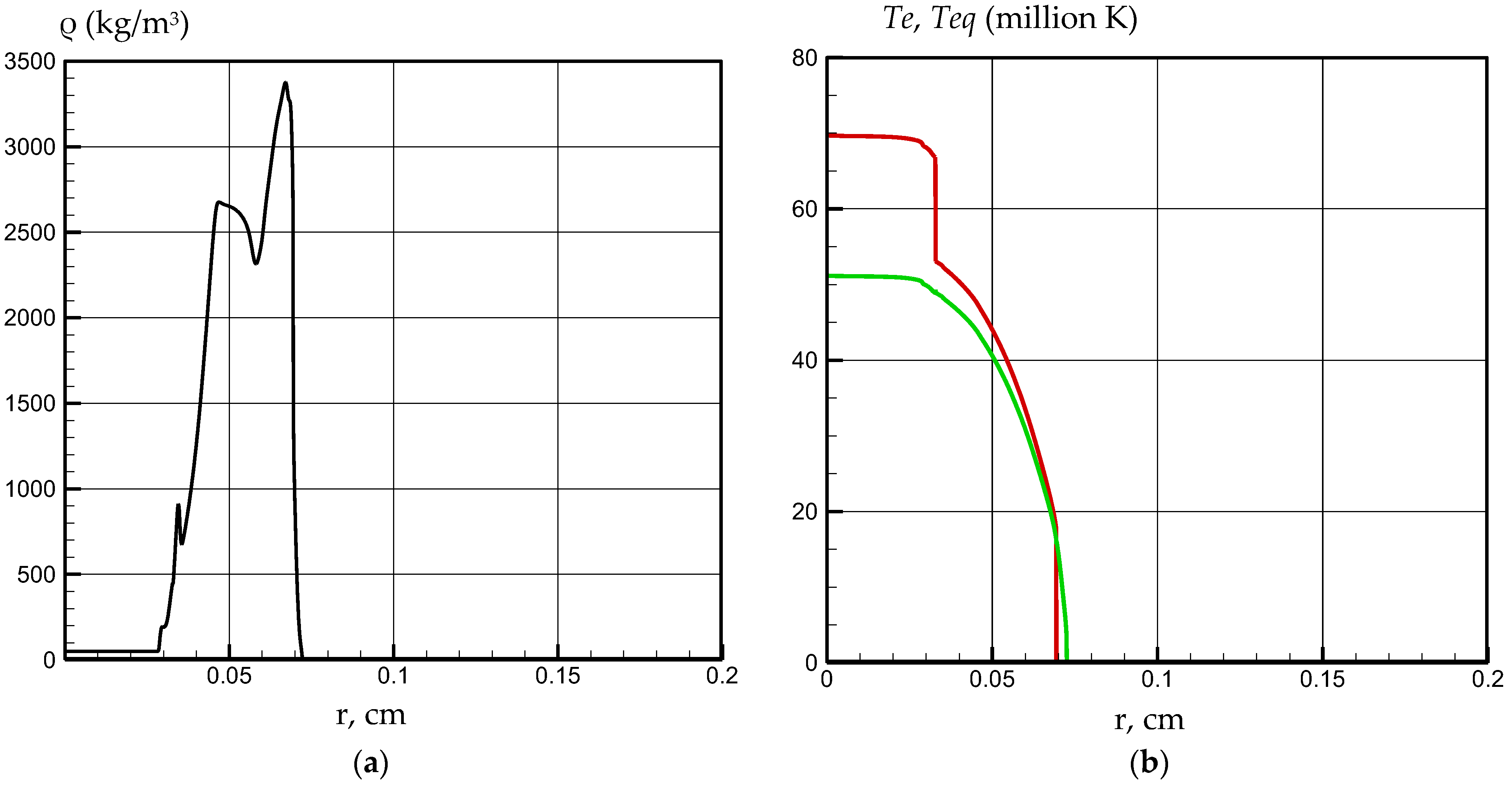
The flow structure (Figure 2) observed in the single-layer case (the “collapse” phase) consists of a “heat wave”, and the formation of a shock wave (in this case, the front of the “heat wave” and the front of the shock wave coincide and are located in the area r = 0.075 cm) in the substance is observed in the time interval 0.4 ≤ t ≤ 0.61 ns.
Figure 3 shows the spatial distribution (multi-layer case Al–Au) of density ρ and average plasma temperature Teq in the MIF target at the “rebound” phase. In this case, multiple transition regions are present. The most important of these are noted as follows: the first shock wave (SW) front is located near the target symmetry axis, and the second SW front is at a distance from the axis. In the region 0.05 ≤ r ≤ 0.06 cm, a significant separation of the average plasma temperature Teq (b) (green line) and electron temperature Te (red line) is observed. It can also be noted that the maximum temperature value is located in the region T ≈ 240–260 million K, which significantly exceeds the maximum temperature level of the single-layer case.
Figure 4 shows the spatial distributions in a single-layer target resulting from intense broadband radiation exposure during the “recompression” phase. By this time, the maximum temperature T and pressure P are located on the geometric axis of the target and reach values of T ≈ 150 million K (slight separation between ion and electron temperatures is observed),   P 8 × 10 9 atm. However, the maximum density ρ = 2.5 × 10³ kg/m3 (where the magnetic pressure of the spontaneous field has a relatively high value of P = 4.5 × 10⁴ atm) is not on the target axis, but in the region of 0.06 ≤ r ≤ 0.075 cm of the most intense broadband radiation absorption.
The simplified physical picture (Figure 4) of the thermophysical processes occurring in the flow interaction region is as follows: after the cumulative reflection (T ≈ 150 million K) of plasma from the target axis, it rapidly expands (u = 600 km/s) with shock wave generation in the peripheral region.
As seen in Figure 1, Figure 2, Figure 3 and Figure 4, the situation described may exhibit a spatial state (for relatively short time intervals Δt < 0.1 ns) where the following relation holds: q + q e / r > Q e i . In this spatial region, “supercooled” or “superheated” plasma [16] may form, which can be in a thermodynamically nonequilibrium (Te ≠ Teq and Z c p Z c p ) state. Here Zcp is the “nonequilibrium” average charge of heavy particles, Z c p n e , T e is the equilibrium average charge of heavy particles, and Teq is the effective temperature that would correspond to the actual equilibrium average charge Z c p of heavy particles under thermodynamic equilibrium conditions.
As noted in [16], in cases where the plasma ionization state is primarily determined by collisions, one can classify (based on parameters existing at time t) the plasma state by the deviation in its heavy particles’ average charge Zcp from the thermodynamic equilibrium value Z c p n e , T e . When Z c p > Z c p , the predominant ions in the given spatial region mainly recombine, while when Z c p Z c p , electrons primarily ionize and excite ions. We also note that at high ionization degrees Z c p > Z c p , the plasma is “supercooled”, and Te < Teq, whereas at low ionization degrees Z c p Z c p , the plasma is “superheated”, and TeTeq. This observed temperature “stratification” (in the considered case near shock wave fronts) is shown in Figure 1, Figure 2, Figure 3 and Figure 4 and occurs during both the “implosion” and “recompression” phases.
Overall, the behavior [16] of electron and ion temperatures in the transition region near the shock (detonation) wave front (Figure 1, Figure 2, Figure 3 and Figure 4) can be qualitatively described by the following main physical mechanisms (accounting for e-i exchange): conductive heating of electrons ahead of the shock front; non-adiabatic heating of electrons behind the shock front; and collisional heat exchange (both ahead and behind the shock front) between electrons and ions. The inclusion of thermal conductivity (particularly “radiative” conductivity [6]) leads to the formation of an electron-gas-heating “tongue” ahead of the shock jump, causing greater increase in Te than would occur with adiabatic heating. Collisional e-i exchange results in an overall electron temperature increase behind the shock front.
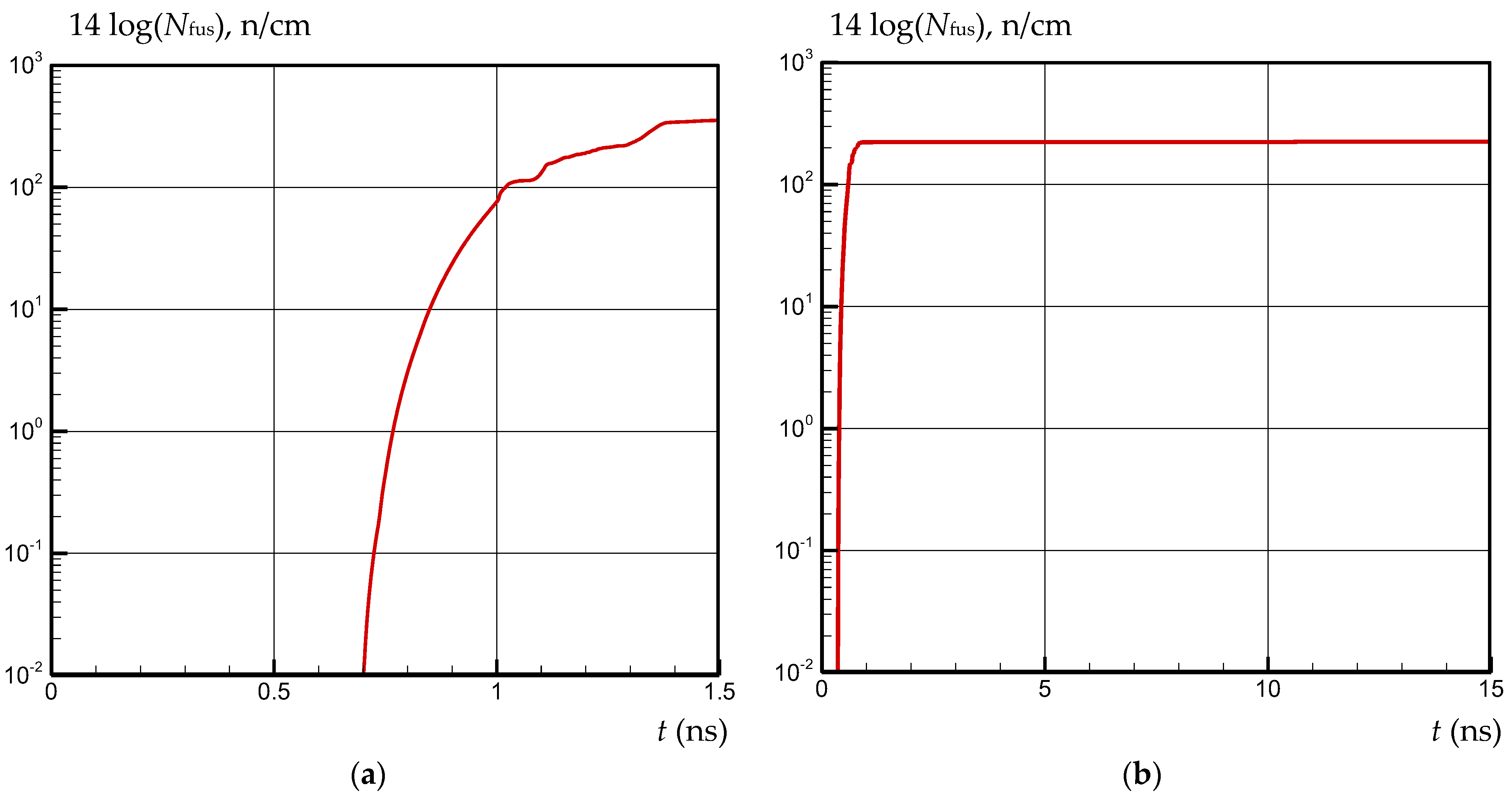
The number of neutrons Nfus can reach levels of 1015 n/cm (for the single-layer case, Al) and 35 × 1015 n/cm (for the multi-layer case, Al–Au) (Figure 5).
We should note that regardless of the chosen target type (single-layer or multi-layer) hydrodynamic instabilities (not accounted for in these calculations) may develop during compression and prevent the achievement of optimal thermonuclear fuel parameters. It should be noted that, for the more accurate calculation of neutron numbers, accounting for mixing of the target material is required. Broadband lasers for fusion experiments have been discussed recently in other works [17,18,19]. Applications of wideband pulses and plasma jets in an external magnetic field have been studied experimentally and theoretically in papers [20,21,22,23,24,25].

4. Conclusions

The paper evaluates the plasma dynamic parameters of a single-layer and multi-layer cylindrical target under the influence of intense broadband radiation fluxes. During the calculations, a new version (developed by the authors of the article) of the numerical solution method for one-dimensional plasma dynamic equations was used. This method is based (for the “hyperbolic” part of the system for Equation (1)) on a nonlinear quasi-monotonic compact polynomial difference scheme of an increased order of accuracy, and for the “parabolic” part of the system of equations, a new (it allows calculations in cases of intense discontinuities in transport coefficients) numerical method is used to solve the magnetic field diffusion equation and the heat equation using a monotonized difference scheme of an increased order of accuracy.
All stages of compression of the target have been analyzed and it is shown that the temperature of the central part of the target can reach the level of T > 200 million K. The possibility of creating neutron generators (the number of neutrons per unit length N f u s = 1.0 × 10 17 n/cm by the time of the end of exposure for a multi-layer target) using external broadband radiation is shown at certain points in time (Figure 5). The 1D calculations of the plasma dynamic parameters of the cylindrical target take into account a wide range of physical effects and generally provide information about the dynamics of processes in areas of the 3D target where the study density is either at its most intense or relatively low., i.e., 1D calculations in principle (without taking into account mutual influence) allow us to obtain pictures of 2D distributions of absorbed energy, plasma dynamic and thermodynamic quantities, and therefore judge the operability of the neutron generator circuit based on the effect of broadband radiation on the target.

Author Contributions

Conceptualization, S.V.R. and V.V.K.; data curation, V.V.K.; formal analysis, S.V.R.; investigation, A.G.P.; software, A.G.P.; supervision, S.V.R.; writing—original draft preparation, V.V.K.; writing—review and editing, S.V.R.; visualization, V.V.K. All authors have read and agreed to the published version of the manuscript.

Funding

This research was supported by the Ministry of Science and Higher Education of the Russian Federation (State Assignment No. FSFN-2024-0022).

Institutional Review Board Statement

Not applicable.

Informed Consent Statement

Not applicable.

Data Availability Statement

The original contributions presented in this study are included in the article. Further inquiries can be directed to the corresponding authors.

Conflicts of Interest

The authors declare no conflicts of interest.

Nomenclature

cthe speed of light
Bzexternal magnetic field, T
EFFermi degenerate energy
Efenergy of the thermonuclear reaction
Eenergy, W/kg
Hmagnetic induction, T
jrcurrent density, A/m2
kBoltzmann constant
Kplasma-specific scaling factor
Nfusnumber of neutrons
nheavy particle, cm−1
neelectron concentration, cm−1
Ppressure, Pa
Peelectron pressure, Pa
Piion pressure, Pa
Pffusion power per unit volume, W/m3
Qeienergy transferred per unit time per unit volume from electrons to ions
Qfuslocal (thermonuclear) energy release to the electron component
qbroadband radiation intensity, W/cm2
qLLaser intensity, W/cm2
qrenergy flux from the magnetic field, W/cm2
qvspectral broadband radiation flux, W/cm2
qtermdensity of the external broadband radiation flux perpendicular to the target
rradial coordinate, m
ttime, s
Teqaverage plasma temperature
Teelectron temperature, K
Tiion plasma temperature, K
uvelocity along the coordinate, m/s
Uνspectral flux and volumetric density of broadband radiation
VDvelocity of the photodetonation wave, m/s
V f n u c l velocity of the thermonuclear reaction, m/s
v e i , k average frequency of electron–ion collisions, Hz
ρdensity, kg/m3
λeelectron thermal conductivity coefficient, W/(m K)
λiion thermal conductivity coefficient, W/(m K)
τthe duration of the broadband radiation pulse, s
φthe azimuthal angle
Z1proton number of the interacting nuclei 1
Z2proton number of the interacting nuclei 2
Z c p equilibrium average charge of heavy particles
θplasma degeneracy parameter
χradiative thermal diffusivity coefficient
χνspectral absorption coefficient
γadiabatic index of Hugoniot

References

  1. Ananyev, S.; Kukushkin, A. Calculation of Consistent Plasma Parameters for DEMO-FNS Using Ionic Transport Equations and Simulation of the Tritium Fuel Cycle. Appl. Sci. 2023, 13, 8552. [Google Scholar] [CrossRef]
  2. Dlougach, E.; Panasenkov, A.; Kuteev, B.; Serikov, A. Neutral Beam Coupling with Plasma in a Compact Fusion Neutron Source. Appl. Sci. 2022, 12, 8404. [Google Scholar] [CrossRef]
  3. Garanin, S.G.; Ivanovskii, A.V.; Kulikov, S.M.; Mamyshev, V.I.; Pevny, S.N.; Rogachev, V.G. Inertial Thermonuclear Fusion Using Explosive Magnetic Generators. Plasma Phys. Rep. 2022, 48, 111–120. [Google Scholar] [CrossRef]
  4. Mitrofanov, K.N.; Aleksandrov, V.V.; Branitski, A.V.; Grabovskiy, E.V.; Gritsuk, A.N.; Oleinik, G.M.; Frolov, I.N.; Olkhovskaya, O.G.; Gasilov, V.A. Progress in researching the implosion of nested arrays of mixed composition and the generation of soft X-ray power pulse. Plasma Phys. Control Fusion 2022, 64, 045007. [Google Scholar] [CrossRef]
  5. Chetverushkin, B.N.; D’Ascenzo, N.; Saveliev, V.I. Kinetically consistent magnetogasdynamics equations and their use in supercomputer computations. Dokl. Math. 2014, 90, 495–498. [Google Scholar] [CrossRef]
  6. Zel’Dovich, Y.B.; Rajzer, Y.P. Physics of Shock Waves and High Temperature Phenomena of Hydrodynamic Phenomena; Nauka: Moscow, Russia, 1966. [Google Scholar]
  7. Braginskij, S.I. Transport Processes in a Plasma; Reviews of Plasma Physics; Leontovich, M.A., Ed.; Consultants Bureau: New York, NY, USA, 1965; pp. 205–311. [Google Scholar]
  8. Samarskij, A.A.; Popov, I.P. Difference Methods for Solving Problems of Gas Dynamics; Nauka: Moscow, Russia, 1980. (In Russian) [Google Scholar]
  9. Kuzenov, V.V.; Ryzhkov, S.V.; Varaksin, A.Y. Development of a Method for Solving Elliptic Differential Equations Based on a Nonlinear Compact-Polynomial Scheme. J. Comput. Appl. Math. 2024, 451, 116098. [Google Scholar] [CrossRef]
  10. Surzhikov, S.T. Computing System for Solving Radiative Gasdynamic Problems of Entry and Re-Entry Space Vehicles. In Proceedings of the 1st International Workshop on Radiation of High Temperature Gases in Atmospheric Entry, ESA-533, Lisabon, Portugal, 8–10 October 2003; pp. 111–118. [Google Scholar]
  11. Kuzenov, V.V.; Ryzhkov, S.V.; Shumaev, V.V. Application of Thomas-Fermi model to evaluation of thermodynamic properties of magnetized plasma. Probl. At. Sci. Technol. 2015, 1, 97–99. [Google Scholar]
  12. Xu, Z.; Shu, C.-W. Anti-diffusive flux corrections for high order finite difference WENO schemes. J. Comput. Phys. 2005, 205, 458–485. [Google Scholar] [CrossRef]
  13. Xu, Z.; Shu, C.-W. Anti-diffusive finite difference WENO methods for shallow water with transport of pollutant, J. Comput. Math. 2006, 24, 239–251. [Google Scholar]
  14. Raizer, Y.P. Breakdown and heating of gases under the influence of a laser beam, Sov. Phys. Usp. 1966, 8, 650–673. [Google Scholar] [CrossRef]
  15. Kuzenov, V.V.; Ryzhkov, S.V. Small-sized plasma generators—Sources of high-energy particle and neutron fluxes (review). Fusion Sci. Technol. 2025, 81, 1–11. [Google Scholar] [CrossRef]
  16. Derzhiev, V.I.; Zhidkov, A.G.; Yakovlenko, S.I. Radiation of Ions in a Nonequilibrium Dense Plasma; Energoatomizdat: Moscow, Russia, 1986. (In Russian) [Google Scholar]
  17. Paradis, C.; Hammond, D.; Thoma, J.; Loescher, A.; Le Touzé, G.; Friedman, G.; Le Garrec, B.; Chériaux, G. Advances in laser technology for direct drive inertial fusion energy. Proc. SPIE—Int. Soc. Opt. Eng. 2025, 13343, 1334302. [Google Scholar] [CrossRef]
  18. Follett, R.K.; Colaïtis, A.; Seaton, A.G.; Wen, H.; Turnbull, D.; Froula, D.H.; Palastro, J.P. Ray-based cross-beam energy transfer modeling for broadband lasers. Phys. Plasmas 2023, 30, 042102. [Google Scholar] [CrossRef]
  19. Zhang, X.; Ji, L.L.; Liu, D.; Gao, Y.Q.; Sui, Z.; Zhao, X.H.; Xiang, X. Numerical simulation on third-harmonic generation of super-luminescent light by mixing broadband and narrowband lasers. Chin. J. Lasers 2021, 48, 2108001. [Google Scholar] [CrossRef]
  20. Zudin, I.; Gushchin, M.; Korobkov, S.; Strikovskiy, A.; Katkov, A.; Kochedykov, V.; Petrova, I. Transformation of the Shape and Spectrum of an Ultrawideband Electromagnetic Pulse in a “Gigantic” Coaxial Line Filled with Magnetized Plasma. Appl. Sci. 2024, 14, 705. [Google Scholar] [CrossRef]
  21. Nikolenko, A.S.; Gushchin, M.E.; Korobkov, S.V.; Strikovskiy, A.V.; Loskutov, K.N. Dynamics of a Plasma Cloud Generated by a Compact Coaxial Gun upon Expansion into Vacuum and Large-Volume Background Plasma in an External Magnetic Field. Plasma Phys. Rep. 2023, 49, 1284–1299. [Google Scholar] [CrossRef]
  22. Es’kin, V.A.; Korobkov, S.V.; Gushchin, M.E.; Kudrin, A.V. Propagation of an Ultrawideband Electromagnetic Pulse Along a Plasma-Filled Coaxial Line. IEEE Trans. Plasma Sci. 2023, 51, 374–380. [Google Scholar] [CrossRef]
  23. Sladkov, A.; Fegan, C.; Yao, W.; Bott, A.F.A.; Chen, S.N.; Ahmed, H.; Filippov, E.D.; Lelièvre, R.; Martin, P.; McIlvenny, A.; et al. Saturation of the compression of two interacting magnetized plasma toroids evidenced in the laboratory. Nat. Commun. 2024, 15, 10065. [Google Scholar] [CrossRef] [PubMed]
  24. Korobkov, S.V.; Nikolenko, A.S.; Gushchin, M.E.; Strikovsky, A.V.; Zudin, I.Y.; Aidakina, N.A.; Shaikhislamov, I.F.; Rumenskikh, M.S.; Zemskov, R.S.; Starodubtsev, M.V. Features of Dynamics and Instability of Plasma Jets Expanding into an External Magnetic Field in Laboratory Experiments with Compact Coaxial Plasma Generators on a Large-Scale “Krot” Stand. Astron. Rep. 2023, 67, 93–103. [Google Scholar] [CrossRef]
  25. Savenko, N.O.; Urvachev, E.M.; Losseva, T.V.; Grushin, A.S.; Poklad, Y.V.; Gasilov, V.A. Numerical Simulation of Plasma Jet Expansion in a Laboratory Experiment. Plasma Phys. Rep. 2025, 51, 697–707. [Google Scholar] [CrossRef]
Figure 1. Spatial distribution (multi-layer case Al–Au): (a) density (orange line), ρ (kg/m3) and (b) average plasma temperature Teq (green line) and electron temperature Te (red line) at the time moment t = 0.78 ns. Positions of the contact boundaries (green line in (a)): 1 between D-T and Al; 2 between Al and Au, and 3 between Au and air.
Applsci 15 11155 g001
Figure 2. Spatial distribution (single-layer case: Al): (a) density, ρ (kg/m3) and (b) average plasma temperature Teq (green line) and electron temperature Te (red line) at time moment t = 0.4 ns.
Applsci 15 11155 g002
Figure 3. Spatial distribution (multi-layer case Al–Au): (a) density (orange line), ρ (kg/m3) and (b) average plasma temperature Teq (green line) and electron temperature Te (red line) at time moment t = 1.03 ns. Positions of contact boundaries (green line in Figure 1a and Figure 3a): 1 between D-T and Al, 2 between Al and Au, and 3 between Au and air.
Applsci 15 11155 g003
Figure 4. Spatial distribution (single-layer case: Al): (a) density, ρ (kg/m3) and (b) average plasma temperature Teq (green line) and electron temperature Te (red line) at time moment t = 0.62 ns.
Applsci 15 11155 g004
Figure 5. The number of neutrons Nfus (n/cm) that have left the computational domain by time t: (a) multi-layer case Al–Au and (b) single-layer case: Al.
Applsci 15 11155 g005
Disclaimer/Publisher’s Note: The statements, opinions and data contained in all publications are solely those of the individual author(s) and contributor(s) and not of MDPI and/or the editor(s). MDPI and/or the editor(s) disclaim responsibility for any injury to people or property resulting from any ideas, methods, instructions or products referred to in the content.