Article

Safety Evaluation of Composite Wall Systems Subjected to Projectile Impact

Chair of Research and Studies in Strengthening and Rehabilitation of Structures, Department of Civil Engineering, College of Engineering, King Saud University, P.O. Box 800, Riyadh 11421, Saudi Arabia
*
Author to whom correspondence should be addressed.
Appl. Sci. 2025, 15(20), 11128; https://doi.org/10.3390/app152011128
Submission received: 3 September 2025 / Revised: 26 September 2025 / Accepted: 9 October 2025 / Published: 17 October 2025

Abstract

Featured Application

The findings of this study highlight the promising application of the composite wall system. This system consists of two reinforced concrete (RC) walls with a gap in between, which may or may not contain a filling, and functions as an effective protective barrier in structures exposed to projectile impacts. Typical applications include defense facilities, nuclear installations, storage units for hazardous materials, and critical infrastructure. By optimizing wall thickness ratios and selecting appropriate gap-filling materials, the composite system provides significantly higher safety and reliability than conventional monolithic RC walls, even under severe impact scenarios. Its adaptability, achieved through varying gap widths, filler densities, and reinforcement layouts, offers engineers a versatile and resource-efficient solution. Moreover, it enables the use of sustainable materials, such as recycled concrete aggregates, enhancing both structural resilience and environmental sustainability.

Abstract

This study evaluates the structural safety of composite RC wall systems, which consist of outer and inner RC walls with either an empty or a filled gap, against projectile impacts. The system is considered to have failed if its ballistic limit falls below the projectile’s striking velocity. To determine this limit, the wall system is transformed into an equivalent monolithic wall of the same total reinforcement and perforation energy. A modified UKAEA formula was employed to estimate this limit. To perform the reliability assessment, as the experiments were limited, over one million composite walls were simulated, and the probability of failure and reliability were estimated. Results show that, by leaving the gap unfilled between equally thick inner and outer walls, safety improves by 49.2% compared to a monolithic wall; the safety increases further to 68.2% and 68.9% by filling the gap with sand and recycled concrete aggregate, respectively. Greater gains occur with unequal wall thicknesses: 62% (no fill), 95% (sand), and 96% (recycled aggregate). Parametric analysis demonstrated the influence of filling density, gap thickness, and wall thickness ratios on system reliability. Overall, the findings confirm the superior protective performance and higher safety of composite wall systems compared to monolithic walls.

1. Introduction

Two reinforced concrete (RC) walls kept at some distance apart constitute a composite wall system (CWS). This configuration may include a filling or remain unfilled. Recent experimental research by the authors has demonstrated that such a system with granular fillings provides a superior impact response compared to a monolithic RC wall of equivalent total thickness [1]. However, the quantitative improvement in the safety level of such a promising composite wall system was not known. In this study, the improvement in safety level, measured in terms of the probability of failure or reliability index, of the composite wall system relative to the same total thickness monolithic RC wall is studied.
The utilization of composite wall systems in protective structures is still relatively uncommon. Conventional defense facilities, such as military bunkers and war shelters, predominantly employ massive monolithic concrete walls and slabs to withstand missile and projectile impacts. In contrast, the adoption of composite wall configurations has been limited to a few specialized shelters (see Figure 1). This limited adoption is primarily due to the scarcity of systematic research and experimental studies in this domain.
The studies on composite walls subjected to projectile impact are limited. The available studies are primarily on sandwich panels with cores. Abbas et al. [1] carried out experiments to evaluate how granular infill placed between two reinforced concrete (RC) walls can enhance the impact resistance of composite wall systems compared to traditional monolithic RC walls. They prepared specimens to simulate both composite and monolithic configurations and subjected them to single and repeated impacts using hemispherical nose projectiles. The experimental outcomes revealed that the composite wall systems not only achieved higher impact resistance and ballistic limits but also outperformed the monolithic walls significantly. Additionally, the study introduced a model for predicting the mass of material ejected during impact. Tao et al. [3] studied the impact dynamics and energy absorption performance of sandwich panels under conditions of high-speed impact. They employed 3D digital image correlation in conjunction with high-speed imaging to analyze the dynamic deflection of the rear sheets. The results showed that variations in core density and thickness had a substantial impact on the ballistic limit velocity, while penetration led to minimal localized permanent deformation. Zhang et al. [4] performed experiments on fluid-filled containers with an aluminum wall and a composite aluminum/rubber wall to investigate the impact of the rubber layer on structural damage resulting from high-velocity projectile impacts. High-speed cameras and pressure transducers were used to record the impact events. Their findings revealed that the rubber in the composite wall successfully attenuated shock pressure (reflected) and minimized structural deformations.
Aktay et al. [5] investigated the performance of sandwich panels featuring aramid paper honeycomb and PEI foam cores subjected to transverse impacts. Using the PAM-CRASH software, they developed a numerical model. Their findings showed that the model effectively replicated the outcomes of high-velocity impact experiments for both sandwich panel configurations. Gupta et al. [6] examined how steel impactors with hemispherical, ogive, and flat-nose profiles interact with the stacked aluminum plates with differing thicknesses. Using a pneumatic gun, they tested projectiles with different nose shapes and velocities. Both their experimental tests and finite element (FE) simulations provided data on residual and ballistic limit velocities for each aluminum plate configuration. Their results revealed that (i) two-layered plates exhibited residual velocities comparable to single plates, (ii) ogive-nosed projectiles demonstrated the highest penetration efficiency, and (iii) the FE simulation results closely matched the experimental findings.
Siddiqui et al. [7] developed a method to evaluate double-wall containment systems’ reliability under impact loads generated by rigid projectiles. Their assessment focused on the outer reinforced concrete wall’s ballistic limit when struck by a specific projectile. The study concluded that the containment structure could be considered “sufficiently safe” as long as the projectile’s impact velocity did not exceed 65% of the wall’s ballistic limit. Dancygier et al. [8] experimentally studied the impact resistance of high-performance concrete (HPC) barriers against non-deforming projectiles. The research examined the effects of aggregate size, steel fiber content, and layering on impact performance. The study output showed that the strategic use of steel fibers and aggregates of larger sizes significantly enhanced the impact strength of different concrete layers. Siddiqui et al. [9] designed an experiment to model a containment system with two walls, focusing on the impact resistance of steel plates shielded with reinforced concrete walls to ogive and biconical-nose projectiles. Their study also evaluated the safety of the shielded steel plate against projectile impacts. Using the Monte Carlo simulation (MCS), they assessed the reliability of shielded steel plates subjected to impact velocities of different magnitudes. They also determined the failure probability of shielded steel plates under various failure scenarios. Wu et al. [10] performed high-speed impact tests on high-strength concrete panels reinforced with steel fibers (SFRHSC). These panels had liners of steel on the backside and, in some cases, a backfilled layer of sandy soil. Their study revealed that (i) SFRHSC/steel composite targets demonstrated enhanced impact resistance when supported by sandy soil; (ii) steel-lined targets outperformed SFRHSC-sand composite targets in impact resistance; (iii) adding a sand layer behind SFRHSC panels provided greater impact resistance benefits than steel liners; and (iv) incorporating steel fibers significantly minimized damage to the concrete targets. Wu et al. [11] investigated five types of reinforced concrete (RC) panels with liners (made up of steel), incorporating both monolithic and segmented designs. Their findings indicated that segmented targets of stacked-type offered greater impact resistance than segmented targets of spaced-type, having a similar thickness and subjected to the same projectile velocity. Feng et al. [12] experimentally and numerically studied the response of projectile impact on targets having two layers composed of ultra-high-performance FRC and armor steel. Their study evaluated residual penetration depth, failure modes, and perforation behavior, providing insights into the ballistic performance of UHPFRC plates.
Ebrahimi et al. [13] conducted detailed finite element simulations to analyze the response of honeycomb sandwich panels to impulsive pressure and high-velocity projectile impacts. Their findings offered valuable insights into the panels’ behavior and failure mechanisms, contributing to the development of more structurally resilient systems. Liu et al. [14] investigated the high-velocity impact response of sandwich panels having the skins of metal fiber laminate (FML) and cores of aluminum foam. They performed impact tests using a gas gun, striking the panels with steel ball bearings at 210 m/s. In addition, they created a finite element model to examine the projectile’s shape and angle effects on the behavior of the sandwich panels. Li et al. [15] developed a composite bulkhead composed of multiple layers on both the front and back. Their study revealed that the front plate experienced combined damage, causing excessive deformation and shear plugging. Moreover, they demonstrated that these composite structures made up of multiple layers are more than 60% lighter than their steel counterparts while providing comparable penetration resistance. Lai et al. [16] investigated high-performance concrete (UHPC) containing a combination of various fibers and aggregates composed primarily of corundum under repeated impacts of bullets. They studied the damage patterns on both the projectiles and concrete targets after each impact. They noticed that the fibers and aggregates significantly enhanced the UHPC’s impact resistance to successive penetrations. Their FE simulations and developed model showed strong agreement with the measured penetration depths.
Wang et al. [17] designed various reinforced concrete (RC) walls incorporating different configurations of transverse reinforcement and conducted large-scale tests using rigid projectiles. Their results highlighted that transverse reinforcement played a crucial role in determining failure modes and mitigating damage to the backside of the concrete. Notably, walls with U-shaped reinforcement (i.e., transverse reinforcement) demonstrated enhanced perforation resistance. Choi et al. [18] explored the impact response of layered panels composed of high-strength and high-ductility fiber-reinforced composites. They subjected the panels to both static loading and high-velocity projectile impacts. The study revealed that panels with high-strength and high-ductility composites at the front and back, respectively, delivered enhanced impact response compared to other configurations that exhibited different damage patterns. Salhan and Rashid [19] carried out projectile impact studies on carbon/epoxy composites and aluminum alloy honeycomb cores. They examined how projectile obliquity and shape affected various ballistic parameters and discovered that the carbon/epoxy composites were capable of absorbing a substantial amount of strain energy before failure.
Zhang et al. [20] investigated the mechanism of penetration in ultra-high-performance concrete (UHPC) having high-strength steel bars (HSSB) and subjected to high-velocity projectile impacts. Their findings revealed that HSSB-UHPC, with its superior strength and toughness, offered remarkable resistance to penetration, achieving significantly lower penetration depths compared to conventional concrete.
Remennikov et al. [21] combined experimental work with numerical simulations to study hypervelocity impacts on various steel-concrete (SC) barrier systems, including non-, partially, and fully composite designs. Their research demonstrated that all these protective systems successfully halted projectiles having high velocities by harnessing the combined strength of both concrete and steel plates. Shao et al. [22] examined the behavior of ultra-high strength concrete (UHSC) targets that were reinforced with energy-absorbing, lightweight and tough composites to resist projectile impact and its penetration. Their combined experimental and numerical analyses revealed that wired meshes and foam within the UHSC target collectively absorbed most of the projectile’s kinetic energy.
The literature review clearly shows that replacing thick monolithic concrete walls with RC composite walls can greatly improve impact resistance. However, it is still crucial to determine whether incorporating granular fillings—such as sand, silt, clay, or recycled stone waste—between two RC walls can offer an even higher level of safety under impact loading compared to an equally thick monolithic RC wall. This study examines how granular fillings affect the safety performance of composite wall systems and compares these findings with those of a corresponding single/monolithic RC wall. The total thickness of composite walls can be provided by making the front and rear walls equal or unequal in thickness. In this paper, the effect of a thickness (equal or unequal) of the front and rear walls on the reliability of composite walls will also be investigated. The reliability of the composite wall system under solid, nondeforming projectile impacts will be evaluated using a simulation-based probabilistic approach. This approach accounts for uncertainties in design parameters such as geometry, material properties, and impact conditions. This study is expected to provide valuable insights for researchers, civil engineers, and architects by highlighting the effect of parameters that influence the response and overall reliability of composite wall systems subjected to projectile impacts.

2. Composite Materials and Systems for Impact Protection

A wide range of composite materials and systems has been developed for protection against projectile and fragment impacts, which are custom-made to specific velocity ranges and applications. The selection of a suitable material depends not only on its ballistic performance but also on its adaptability, scalability, and cost-effectiveness [23,24]. Several review articles are available in the literature that comprehensively examine different aspects of impact protection and provide properties of different materials employed for this purpose [25,26,27,28].
Aramid fibers, such as Kevlar [29,30], are widely used in soft armor for personal protection equipment, including helmets and bulletproof vests, primarily due to their high energy absorption, low density, and high tensile strength [31,32,33]. They are effective at dissipating the kinetic energy of bullets at moderate velocities (up to approximately 500 m/s) [34]. However, their susceptibility to UV degradation, poor performance under sustained compressive forces, and high cost restrict their adoption in large-scale civil infrastructure [35,36,37]. Although nano-coatings have been explored to enhance UV resistance, such treatments further increase overall material cost [38,39].
Ultra-high-molecular-weight polyethylene (UHMWPE) composites exhibit excellent impact resistance and energy absorption capacity, often exceeding aramids in lightweight armor systems [30,40]. The impact performance of these composites has been studied in many past studies [41,42,43]. Their low density makes them attractive for vehicle armor; however, poor fire resistance and high creep under sustained loads make them unsuitable for civil infrastructures [44].
Ceramic composites, such as alumina or silicon carbide, are highly effective in resisting high-velocity and armor-piercing projectiles owing to their hardness and ability to shatter or blunt the projectile [45,46,47]. Despite these advantages, their brittleness and high cost limit their application in large-scale civil structures, though they remain essential in specialized military-grade armor and protective barriers [24].
Reinforced concrete (RC) composites do not provide the same specific energy absorption as advanced fiber-based systems; yet, they remain the most practical solution for structural impact protection because of their inherent mass, compressive strength, availability, and cost-effectiveness [1,48,49,50]. RC contributes significant inertia against penetration, and when combined with fiber-reinforced polymers, hybrid systems can be developed that offer both structural capacity and enhanced ballistic resistance. The present study builds on this principle by investigating layered targets in which a granular, low-cost material is sandwiched between two RC wall panels of different thicknesses, with the objective of achieving improved performance compared to monolithic RC targets [1]. Importantly, the outer RC layer of this system is used as a sacrificial layer, which can be replaced if damaged during projectile impact, providing a sustainable and cost-efficient solution to post-damage repair. The effectiveness and reliability of this composite system against projectile impacts are evaluated through reliability analysis in this study.

3. Formulation for Reliability Analysis of Composite Wall System

The primary goal of this reliability study is to determine the likelihood (or probability) that the composite wall system remains within the specified limit state under the impact of a non-deforming solid projectile. A violation of the limit state occurs when the ballistic limit of the composite system of walls falls below the projectile’s striking velocity. Conversely, failure is defined as the condition in which the projectile’s striking velocity exceeds the ballistic limit of the wall system. The limit state is mathematically represented by a performance or limit state function, which can take zero or non-zero (positive or negative) values. A negative function value or zero function value signifies failure, while a positive value indicates that the composite wall system remains safe and reliable. The failure probability of a composite wall can, therefore, be expressed as:
P f = P [ g ( x _ ) 0 ]
In the above expression, P f represents the probability of failure of the wall system impacted by a projectile, while g ( x _ ) denotes the limit state function, which determines whether the structure remains intact or fails. The variable x _ is a vector containing the random parameters that influence the limit state function, such as material properties, geometric characteristics, and impact conditions.

3.1. Mathematical Representation of the Limit State Function

To mathematically develop a limit state function, the scenario of a projectile impacting the composite wall system under normal incidence was considered. This assumption ensures a consistent and controlled evaluation of the impact resistance and reliability of the wall system under standardized conditions. The composite wall system was assumed to have failed (i.e., penetrated) if the ballistic limit of the composite wall system fell below the projectile’s impact velocity. If V 0 and V p are impact and ballistic limit velocity, one can mathematically define the limit state function as:
g ( x _ ) = V p V 0

3.2. Ballistic Limit of a Composite Wall System

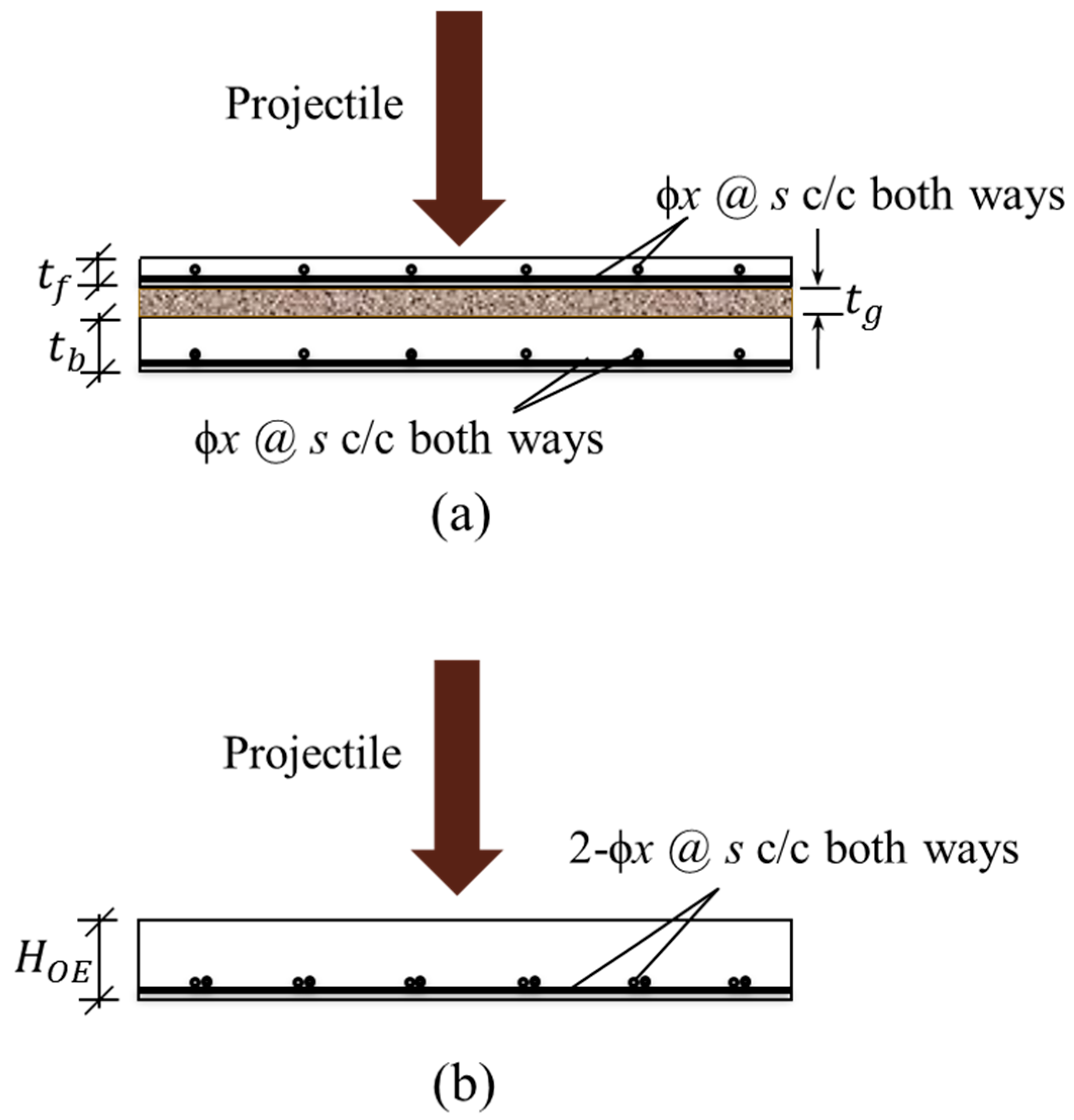
To derive the ballistic limit for a composite wall system, the composite wall system is transformed into an equivalent monolithic wall of thickness H O E (Figure 2). The equivalence is based on perforation energy, i.e., the total perforation energy of the composite wall and its equivalent monolithic wall is the same. Considering this equivalence, the following expression is derived for the thickness of an equivalent monolithic wall:
H O E = α t f + β t b + γ t g t b t f ρ f ρ c
In the above expression, the thicknesses of the front and rear walls are t f and t b , respectively, and the thickness of the filled gap is t g . The coefficients, α , β , and γ are the empirical coefficients. ρ c and ρ f are densities (or unit weights) of concrete and filled material, respectively.
This equivalent thickness was employed to estimate the ballistic limit of the composite wall system and subsequently carry out its reliability analysis. In this equivalent monolithic wall, the distribution of steel was also assumed to be the same as that of the control monolithic wall. The reinforcement was provided to the rear face of the composite wall system. In the present study, the coefficients, α , β , and γ were obtained with the help of tested composite wall systems [1]. The perforation energies of these systems were known. The coefficients were searched within a reasonable limit until the equivalent monolithic wall’s energy for complete penetration (i.e., perforation) matched the experimentally observed perforation energies of the composite wall systems. It should be noted that the values of these coefficients were obtained from a limited number of tests conducted on composite wall specimens of the type, geometry, and material configuration investigated in this study. Thus, their applicability is presently confined to conditions similar to those tested, and further experimental investigations covering broader variations in test parameters are required to refine these coefficients and to assess their general validity.
The literature offers various formulas for forecasting the ballistic limit of RC targets [48]. In this study, a modified UKAEA formula [49,50] was utilized to calculate the perforation velocity, V p , of the equivalent monolithic wall. As per this formula:
V p = V a       f o r   V a   l e s s   t h a n   o r   e q u a l s   t o   70   m / s V a 1 + V a 500 2         f o r   V a   m o r e   t h a n   70   m / s
In which, V a , is given by:
V a = 1.3 ρ c 1 / 6 f c 1 / 2 p H O E 2 π M 2 / 3 ( r + 0.3 ) 1 / 2 ζ
where   ζ = 1.2 0.6 c r H O E 0.5
In the given equations:
  • M represents the projectile mass.
  • H O E denotes the equivalent thickness of the target (i.e., composite wall).
  • p is the perimeter of the projectile’s cross-section, given by π D p .
  • D p is the diameter of the projectile’s aft body.
  • c r represents the spacing of steel rebars.
  • r indicates the percentage of steel rebars, calculated as, r = 2 A ϕ c r d O E 100 .
  • A ϕ is the area (i.e., cross-sectional area) of the steel bars.
  • d O E is the effective depth of the equivalent monolithic wall.
  • f c represents the concrete compressive strength.
These parameters play a crucial role in defining the structural behavior and impact resistance of the composite wall system.
By substituting the expression for V p into Equation (2), the limit state function becomes dependent on the variables ρ c (concrete density), f c (concrete compressive strength), H O E (equivalent thickness of the composite wall), r (steel rebar percentage), c r (rebar spacing), M (projectile mass), D p (projectile diameter), and V o (initial projectile velocity).
Since these variables are subject to considerable uncertainties due to material properties, geometric variations, and impact conditions, they are treated as random variables in this study. The set of these random variables can be represented as:
x _ = ρ c , f c , H O E , r ,   c r ,   M , D p , V o
This probabilistic approach allows for a more realistic assessment of composite wall systems’ impact resistance and reliability.

3.3. Reliability Assessment

The reliability and failure probability of the composite wall system under the action of a rigid projectile were estimated using the Monte Carlo Simulation (MCS) method. In this process, a large ensemble of random realizations of the input parameters is generated, and the resulting outcomes are evaluated based on the limit state function. By analyzing the proportion of failure cases, MCS provides a robust estimation of the composite wall’s reliability under varying impact conditions. MCS involves the following steps:
  • Select those variables that have significant uncertainty as the random variables. Estimate the nominal values of these variables and calculate their required statistics, such as mean, variance, standard deviation, coefficient of variation, etc.
  • Select appropriate probability distributions for all the random variables and calculate the parameters of the probability distributions.
  • Simulate using Monte Carlo Simulation N (~around 1.5 million) composite walls by considering randomness in the material, geometry, and impact-related parameters of the composite walls.
  • Compare each simulated wall’s ballistic limit with the velocity of the impacting projectile.
  • Count the failing number of (composite) walls, i.e., the number of walls having their ballistic limit less than the projectile impact velocity (i.e., having a negative value of the limit state function); say it is N f
  • Calculate the probability of failure of the composite wall ( P f ) and its reliability index ( β ) using the following formulas: P f = N f / N and β = Φ 1 ( P f ) ; in this formulation, Φ 1 P f represents the quantile of the standard normal distribution, obtained via the inverse of its cumulative distribution function [51].
The convergence of MCS is verified through the coefficient of variation (COV) of the failure probability, calculated using [51]:
COV ( P f ) ( 1 P f ) P f N P f
A low coefficient of variation (COV) reflects higher accuracy in the estimation of the failure probability, indicating improved convergence of the Monte Carlo Simulation. If the COV ( P f ) is below 5%, the number of simulations (N) is considered adequate for practical calculations [51].

4. Test Program

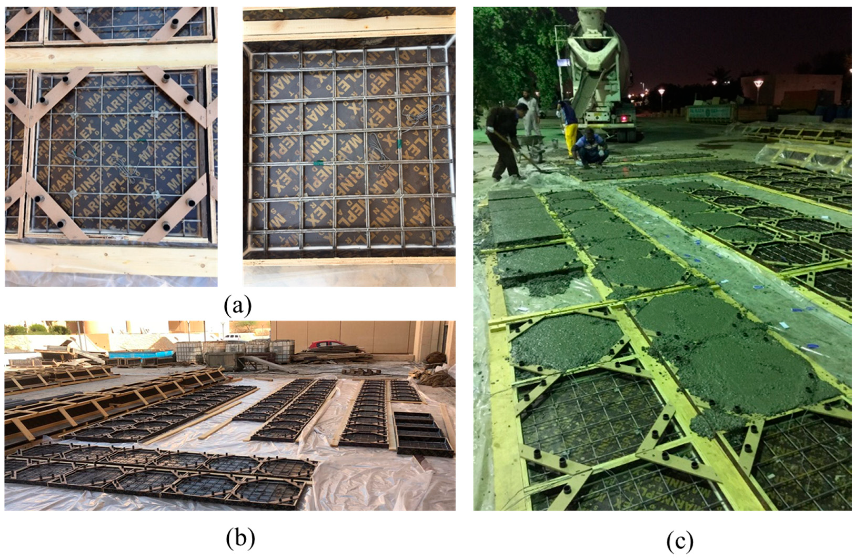
A recent experimental investigation [1] was conducted to simulate the behavior of both monolithic and composite reinforced concrete (RC) walls. The wall specimens were prepared using wooden molds, as illustrated in Figure 3.
The test specimens were divided into three groups, as summarized in Table 1.
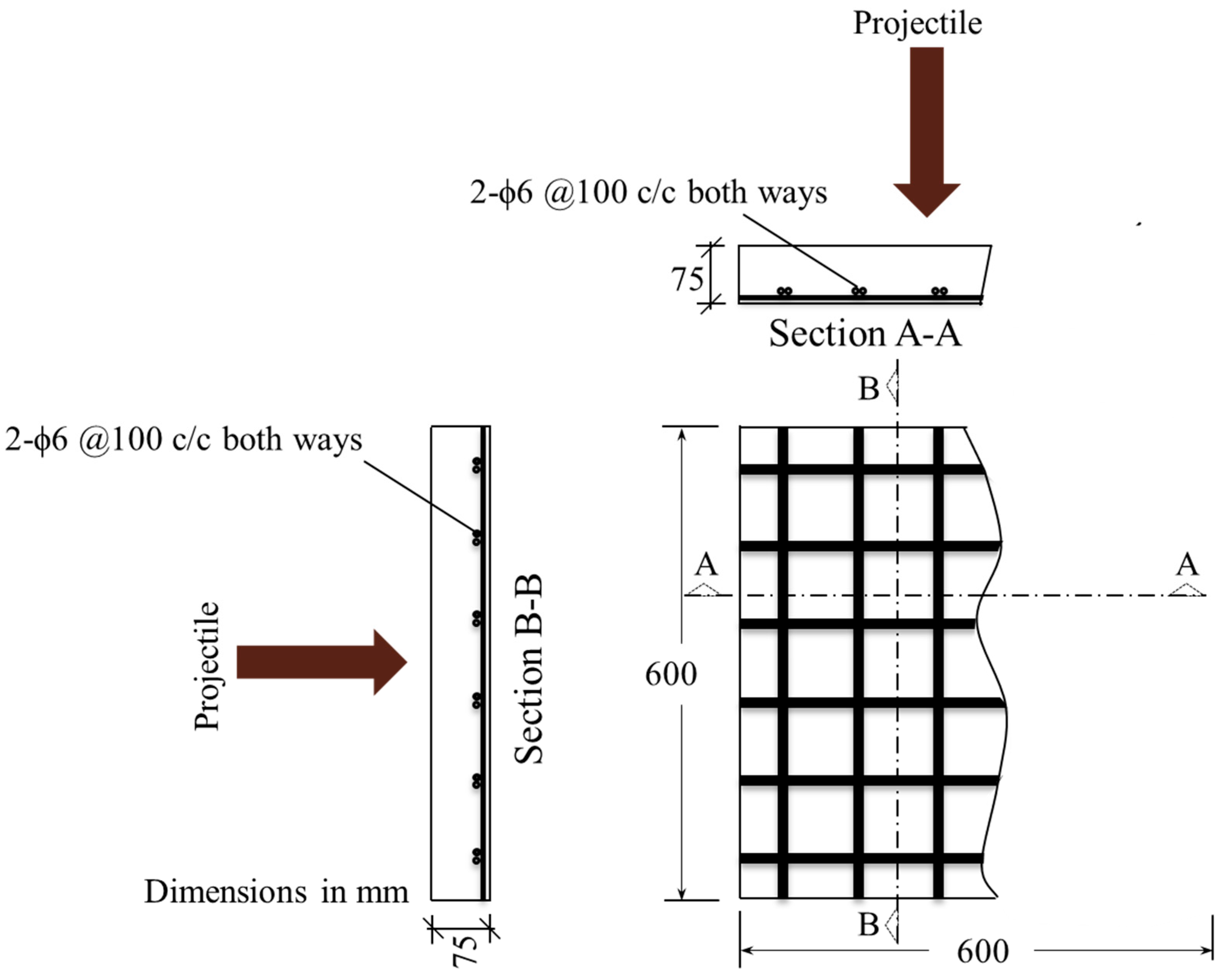
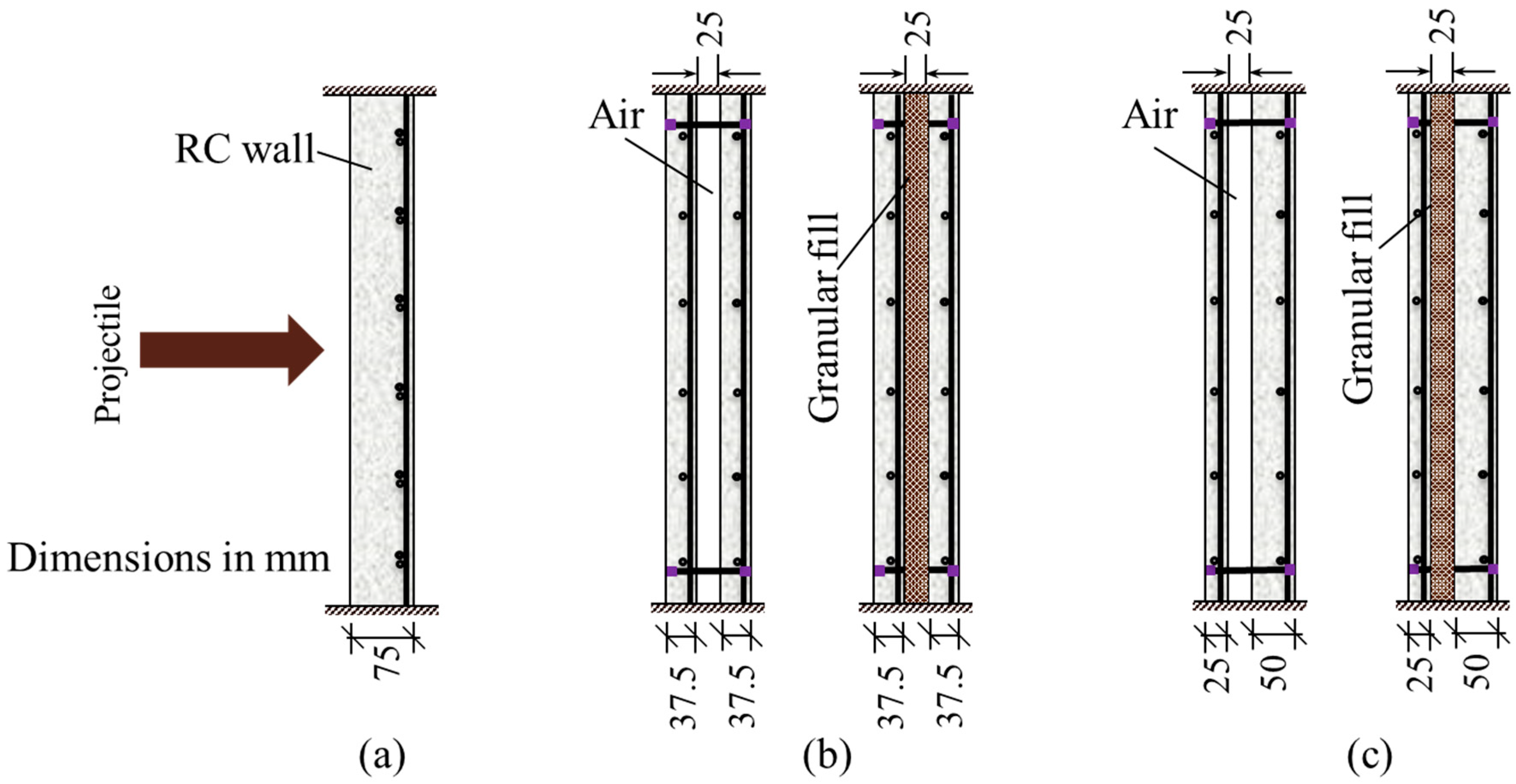
The first group comprised monolithic RC walls, which served as the control set for assessing the structural performance of the composite RC wall configurations. The control specimen consisted of a singly reinforced wall with a thickness of 75 mm. It was reinforced using 2ϕ6 plain mild steel bars arranged at 100 mm center-to-center spacing. The reinforcement was positioned on the rear face of the wall, maintaining a clear cover of 6.5 mm (Figure 4).
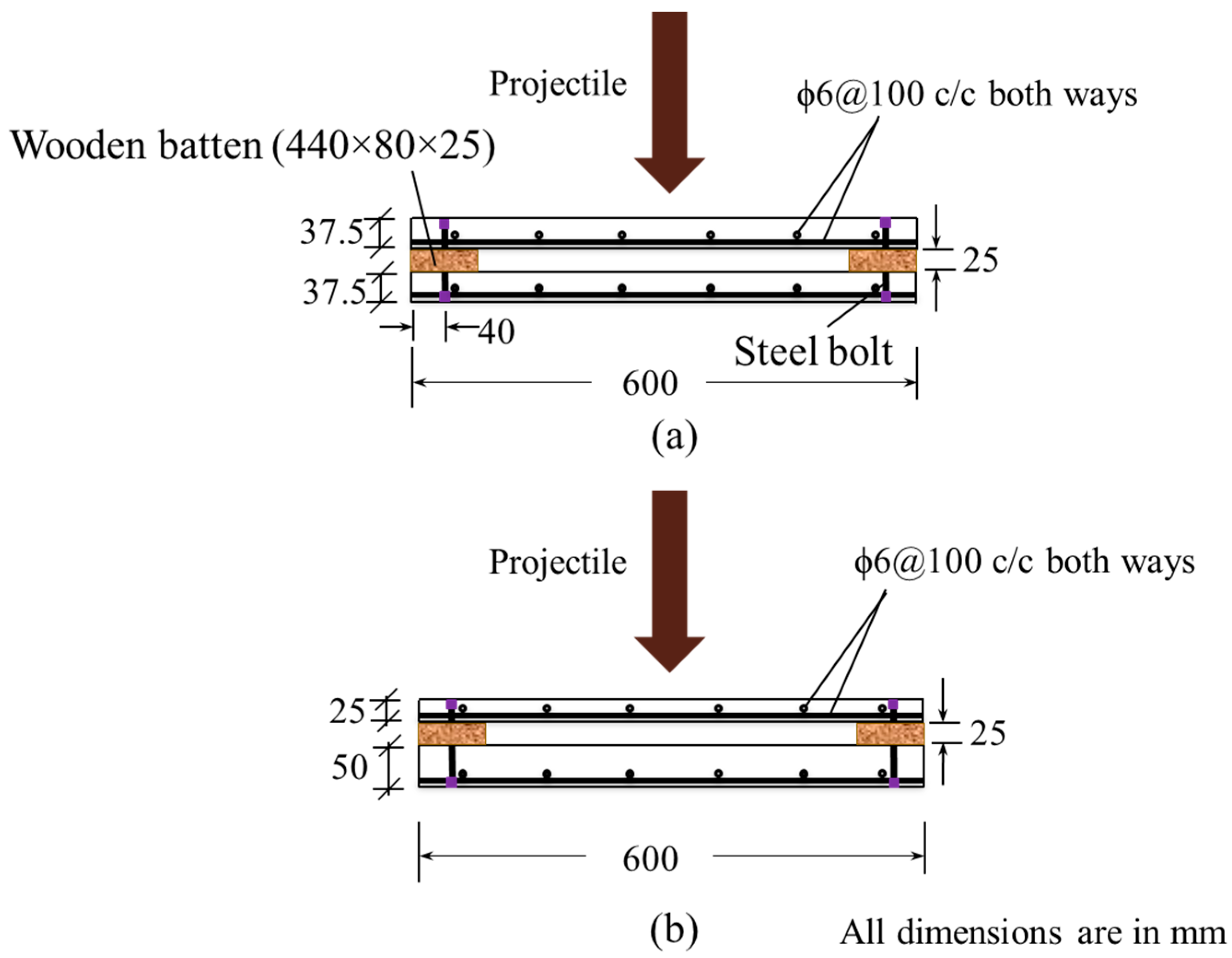
All test specimens were constructed using 6 mm diameter steel rebars of identical grade. The reinforcement was arranged such that the projectile, striking at the center of the target, would not directly impact the rebars. The specimens in the second group featured identical front and back wall thicknesses across all samples, but varied in the type of granular filling materials used. Each specimen was composed of two reinforced concrete walls, each with a thickness of 37.5 mm, representing half the thickness of the control specimen. Both the inner and outer walls were reinforced with ϕ6 plain mild steel bars, spaced at 100 mm center-to-center, maintaining an equivalent total reinforcement to that of the control specimen (Figure 5a). In each wall, the reinforcement was positioned on the rear face with a clear cover of 6.5 mm. A 25 mm gap was provided between the two walls in the test specimens, which was filled with one of two materials: (i) sand compacted at its optimum moisture content, or (ii) recycled concrete aggregate (RCA).
The third group of specimens resembled the second group, with the primary difference being the thickness ratio between the inner and outer reinforced concrete walls. Like the second group, each specimen comprised two RC walls, but these had varying thicknesses (Figure 5b). The wall facing the projectile impact had a thickness of 25 mm, whereas the opposite wall was 50 mm thick. Both walls were reinforced with ϕ6 plain mild steel rebars, spaced at 100 mm center-to-center, ensuring that the total reinforcement remained the same as in the control and composite walls of equal thickness. The reinforcement was placed on the rear face, and a clear concrete cover of 6.5 mm was maintained. As with the specimens of equal thickness, these test specimens had a 25 mm gap between the walls, which was filled with either compacted sand or recycled concrete aggregate (RCA) (Figure 6).
The concrete cover thickness of 6.5 mm was selected to accommodate two layers of 6 mm diameter rebars, placed centrally within the 25 mm thick panel, thereby leaving 6.5 mm of cover on both faces. This cover was maintained in all panels during casting using cover blocks. While the cover was smaller than that recommended by design codes, the specimens were intentionally scaled for laboratory testing in order to preserve structural proportions and rebar detailing relevant to ballistic performance studies. However, for real-world applications, appropriate cover thickness should be adopted in line with the relevant exposure classes and durability requirements prescribed by applicable design standards.
The recycled aggregate used for the cavity filling had a maximum particle size of 12.5 mm. No mechanical compaction was performed, as the aggregate was simply filled in the 25 mm thick cavity and leveled. It should be emphasized that for full-scale, real-world applications, suitable compaction methods should be employed to ensure adequate structural integrity and uniform density of the filler material, which is expected to enhance the overall performance of such composite panels.
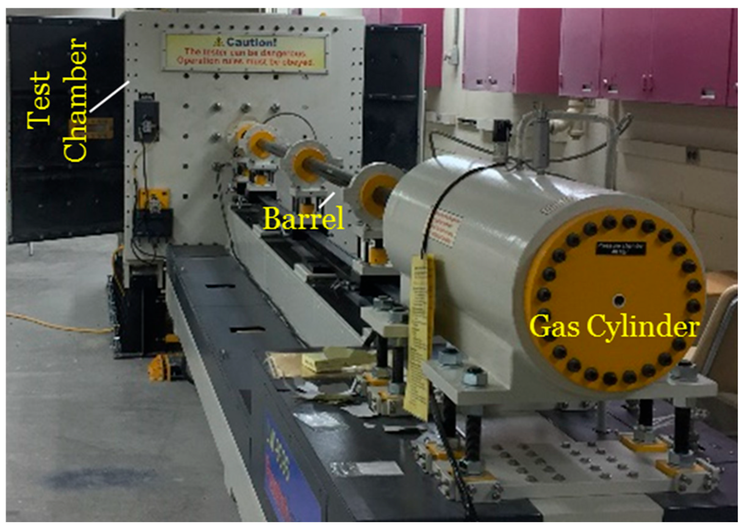
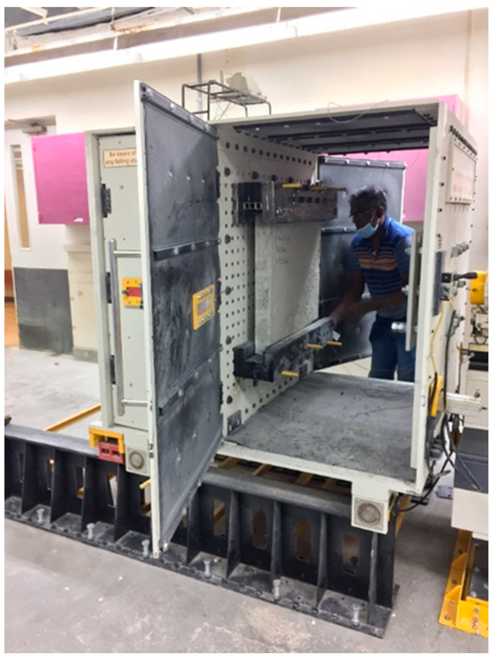
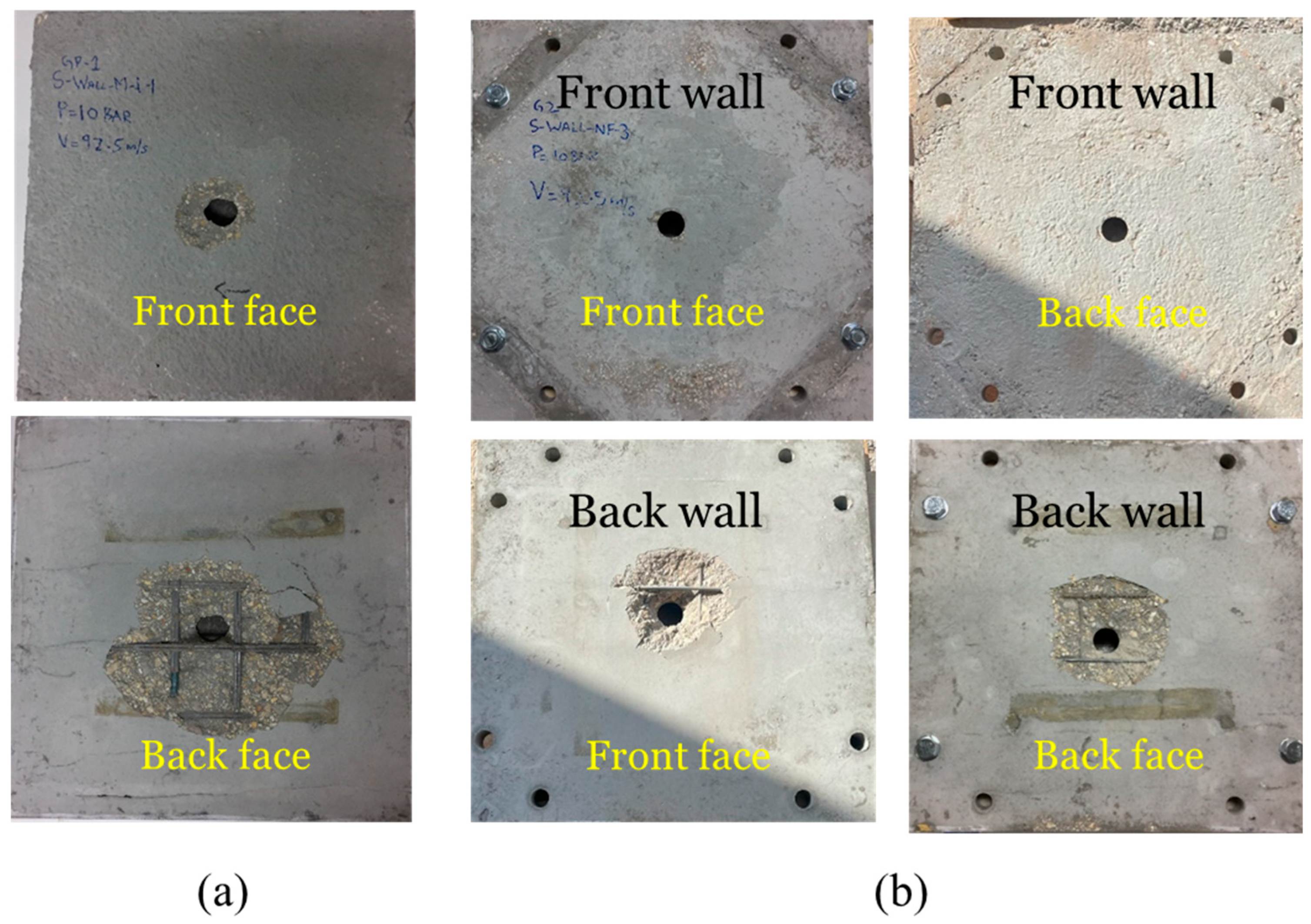
The impact tests were performed using the Longwin gas gun system from Taiwan [52,53], which can propel projectiles at speeds reaching up to 300 m/s (Figure 7). A rigid projectile with a hemispherical nose, weighing 0.8 kg with a diameter of 40 mm, was fired to impact at the specimens’ center (refer to Figure 6). For positioning within the loading frame of the test setup, each specimen was first placed inside the box and securely fastened to the rigid frame using bolts, as illustrated in Figure 8. Proper alignment was verified from the rear face before proceeding. Once correctly positioned, the doors were tightly closed to ensure the required level of safety during testing. Subsequently, the projectile was loaded into the barrel, and the pressure was adjusted to achieve the desired impact velocity. The projectile was then fired to strike the specimen at the desired velocity. When the impact velocity exceeded the ballistic limit of the specimen, complete penetration occurred, with the projectile perforating and exiting the wall (Figure 9).
The impact of a projectile on a target can result in either partial or complete penetration, i.e., perforation. In cases of partial penetration, the projectile’s entire kinetic energy is absorbed in causing damage to the target. When complete perforation occurs, the residual velocity of the projectile must be measured to estimate the perforation energy. During the tests, the residual velocity was recorded using a high-speed camera (10,000 fps), capturing the impact on the rear face of the target. To counter reduced visibility caused by the debris cloud, adequate lighting was provided on the back face of the target chamber. Additionally, videos were recorded over an extended duration to ensure safety and capture the full event.

Equivalent Thickness and Ballistic Limit

Using the formula proposed in Equation (3), the equivalent thickness of each composite wall was estimated. The ballistic limit was then also calculated using Equation (4) through (6). The estimated equivalent thickness and ballistic limits of all the composite walls are shown in Table 1. Comparing the estimated ballistic limit with the experimental findings [1] reveals a close alignment between them (see Table 1). The percentage error in estimating the ballistic limit of composite walls through an equivalent thickness approach for any of the walls is within ±5%, indicating the effectiveness of the equivalent thickness method. The error distribution does not show any consistent overestimation or underestimation across the tested cases, suggesting that the method does not exhibit any systematic bias within the current dataset. However, this observation is based on a limited number of tests, and further validation with an extended experimental dataset would be required to confirm.

5. Input Data for Reliability Assessment

For the reliability analysis of the composite wall systems, critical variables exhibiting significant uncertainty were identified, and their statistical properties, including suitable probability distributions, were established. The random variables incorporated in the analysis are summarized in Table 2. The bias factor in the table is calculated as the ratio of the mean value of a random variable to its nominal (fixed, non-statistical) value. A factor of 1.0 signifies that the mean value corresponds exactly to the nominal value. Generally, resistance-related variables tend to have bias factors greater than 1.0, whereas load variables typically have bias factors below 1.0.
In evaluating the reliability of composite wall specimens, it is essential to identify the probability distribution of the extreme impact load, which is expressed in terms of the projectile’s impact velocity. In this work, the impact velocity is characterized using the Extreme Value Type I distribution [54]. The corresponding probability density function (PDF) and cumulative distribution function (CDF) for this distribution are presented by Nowak and Collins [51]:
P D F = α exp e α ( x u ) exp α ( x u )
C D F = exp e α ( x u )
Here, u and α   denote the distribution parameters. When the mean ( μ x ) and standard deviation ( σ x ) of the impact velocity are known, these parameters can be approximately evaluated using the following relations [51]:
α 1.282 σ x
u μ x 0.45 σ x
In this analysis, the random variables were assumed to be statistically independent, and correlations among them were not explicitly accounted for. It is recognized that in practical situations, certain variables, such as concrete compressive strength and density, may exhibit correlations that could influence the predicted ballistic performance. The error incurred on account of this assumption is expected to be small. However, a more comprehensive approach is suggested for future studies that could incorporate correlations among the random variables or perform sensitivity analyses to assess the effect of these correlations on the simulation results.

6. Discussion of Results

6.1. Composite Walls of Equal Thickness

Table 3 presents the probabilities of failure and reliabilities of various composite wall systems. The walls were subjected to 80% and 90% of the ballistic threshold/limit of the control (monolithic) wall ( V 0 / V B L _ m o n o ). The results show a substantial improvement in safety level when the monolithic wall is replaced by a composite wall with the same total thickness of 75 mm. A projectile striking the monolithic wall at a velocity equal to 0.8 times its ballistic limit (i.e., 80% of its ballistic limit) results in a reliability index of 2.1. The desired reliability index for the majority of the strategic structures is at least 3.0 [7,9,52,54]. This indicates that the monolithic control wall does not provide the desired reliability when subjected to 80% of its ballistic limit. In contrast, the composite walls with the same total thickness, when impacted by the same projectile at the same velocity, exhibit reliability indices greater than 3.0, demonstrating that they meet the minimum (or desired) safety requirements.
Table 3 reveals that leaving the space between the two walls unfilled results in a 49.2% higher safety level than that of the monolithic wall. When this gap is filled with either compacted sand or recycled concrete aggregate (RCA), the reliability of the composite walls rises by 68.2% and 68.9%, respectively, compared with the monolithic configuration. This can be attributed to an increase in the perforation energies (or ballistic limits) of the wall by making it a composite system (Table 1). A comparison of the reliability of filled composite walls with no-fill composite walls illustrates that there is a noticeable effect of filling material on the safety of the composite wall system, as there is an improvement of about 12.7% in the reliability index when the empty gap (air) between the walls is filled with compacted sand. This improvement level changes to 13.2% when the gap is filled with the RCA. The difference in improvement level between sand and RCA is not substantial, as the reliability indices for the two materials are close to each other. Table 3 clearly shows that reinforced concrete (RC) targets composed of two walls with equal thickness demonstrate significantly higher reliability indices compared to a monolithic RC wall of the same thickness. This substantial improvement highlights the synergistic interaction present in double-wall systems, where identical thickness and reinforcement contribute to enhanced structural performance relative to a single, monolithic wall. These findings underscore the advantages of employing composite double-wall configurations for improved reliability under impact loading.

6.2. Composite Walls with Non-Identical Thicknesses

This section examines the reliability and impact performance of composite walls consisting of reinforced concrete layers with non-uniform thicknesses. According to Table 3, the reliability of composite walls formed by two layers of unequal thickness surpasses that of equal-thickness composite walls by 62% to 96%. The improvement stems from the notably greater perforation energy provided by the unequal-thickness configuration [1]. This indicates that an unequal-thickness composite wall system has a better synergistic response than an equal-thickness composite wall system.
The presence of filling material between the two walls helps distribute the impact load across a wider area of the back wall (after the front wall is perforated). In an equal-thickness composite wall system, the thicker front wall is unable to distribute the load over a larger area of the back wall. However, in an unequal-thickness composite system, the thinner front wall allows the load to spread more widely across the back wall. This, in turn, increases the ballistic limit and enhances the reliability compared to an equal-thickness composite wall system. Furthermore, the reduced-thickness front wall functions as a sacrificial element that can be easily replaced once damaged, thereby enhancing the system’s maintainability and extending its overall service life.
While the present study focuses on the ballistic performance of composite wall systems, the findings have practical implications for the design of protective structures. The equivalent thickness method for the layered RC-granular configurations can guide preliminary wall sizing. The use of low-cost granular infills and replaceable outer RC layer offers economic advantages by reducing material and maintenance costs. Furthermore, the modular design enhances construction feasibility, allowing damaged layers to be replaced without affecting the structural integrity of the overall wall. These considerations demonstrate the potential applicability of the proposed system in real-world protective structures. However, the site-specific design would require further engineering evaluation.

7. Parametric Study

In this section, the outcomes of three parametric investigations are outlined to derive results of practical significance. In all the parametric studies, the projectile impact velocity was maintained the same, and it was 90% of the ballistic threshold/limit velocity of a 75 mm thick monolithic wall (i.e., V0 = 0.9 VBL_mono).

7.1. Effect of Unit Weight of the Filling Material

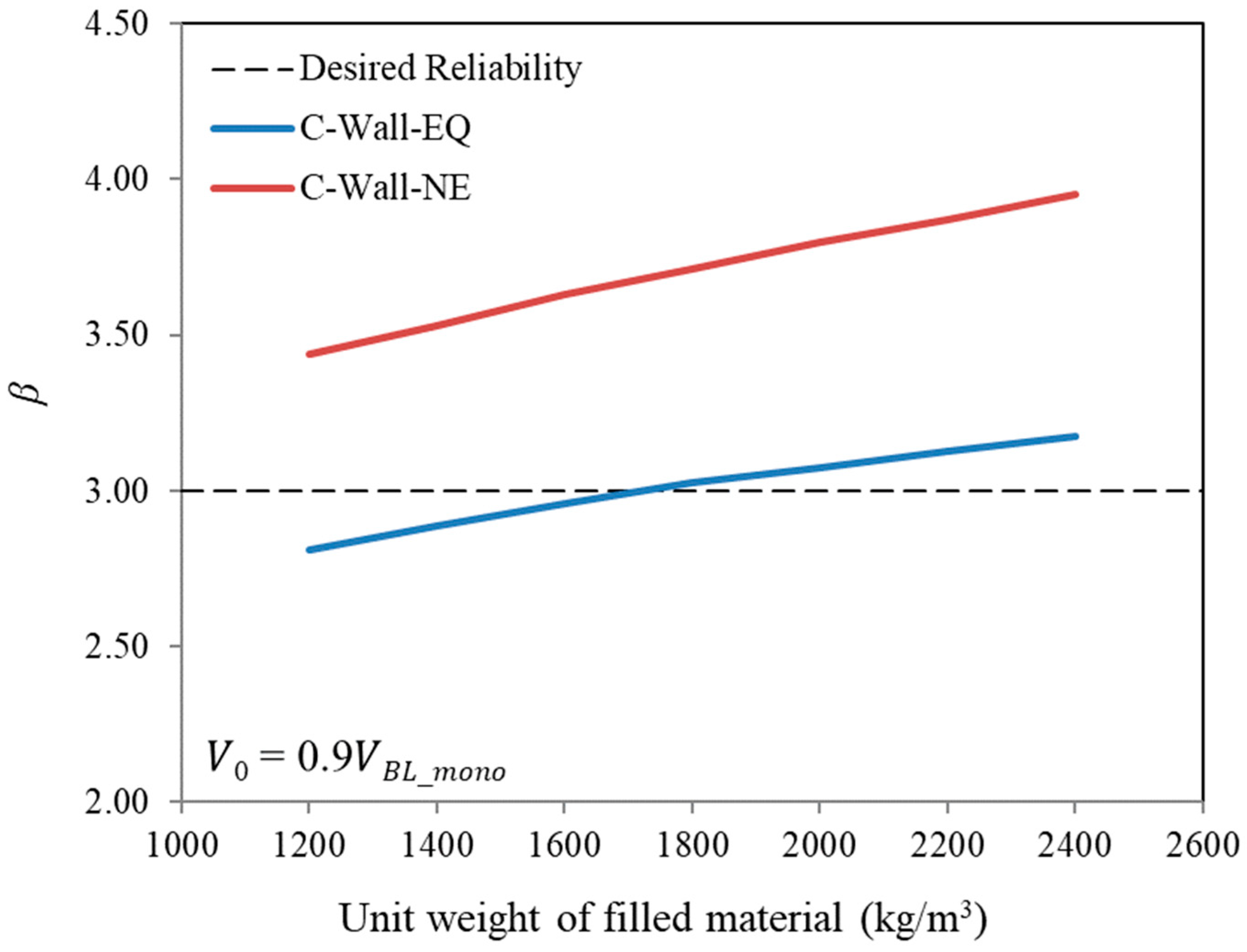
A wide range of options is available to fill the gap between the front and rear walls with various lightweight or normal-weight materials. In the experimental study, we filled the gap between the front and rear walls either with sand (unit weight = 1600 kg/m3) or RCA (unit weight = 1700 kg/m3). In order to examine the influence of filling materials of different unit weights, this parametric investigation involved altering the unit weight within the range of 1200 to 2400 kg/m3. The findings of this study are illustrated in Figure 10. This figure illustrates the vital role of the filling material type. When the filling material is lightweight (unit weight less than 1600 kg/m3), the present composite wall system with equally thick front and rear walls possesses a reliability value less than the minimum required level of safety. However, the reliability index is more than the minimum required value for unequal-thickness composite wall systems, even when the filling material is lightweight.

7.2. Effect of Gap Thickness

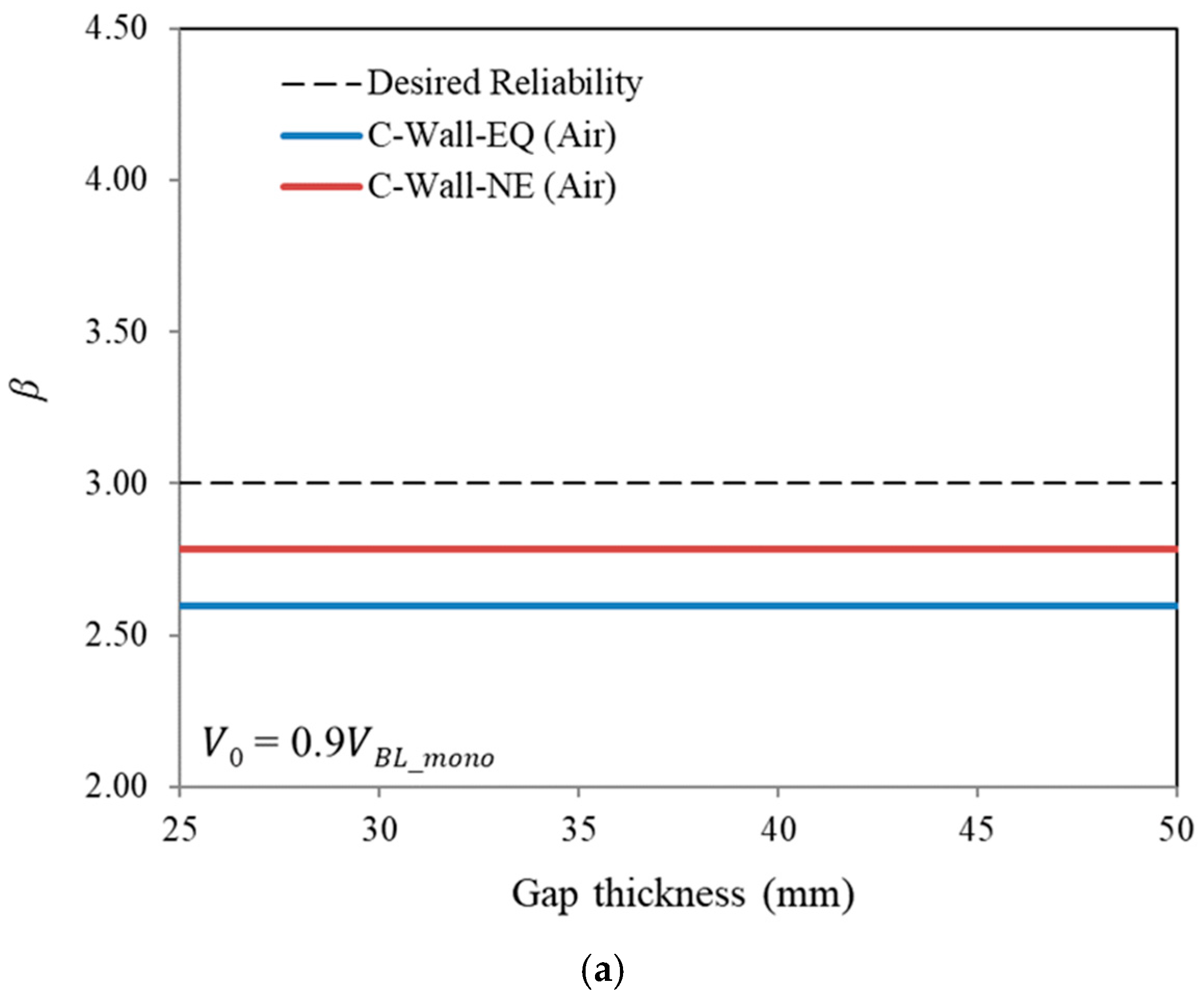
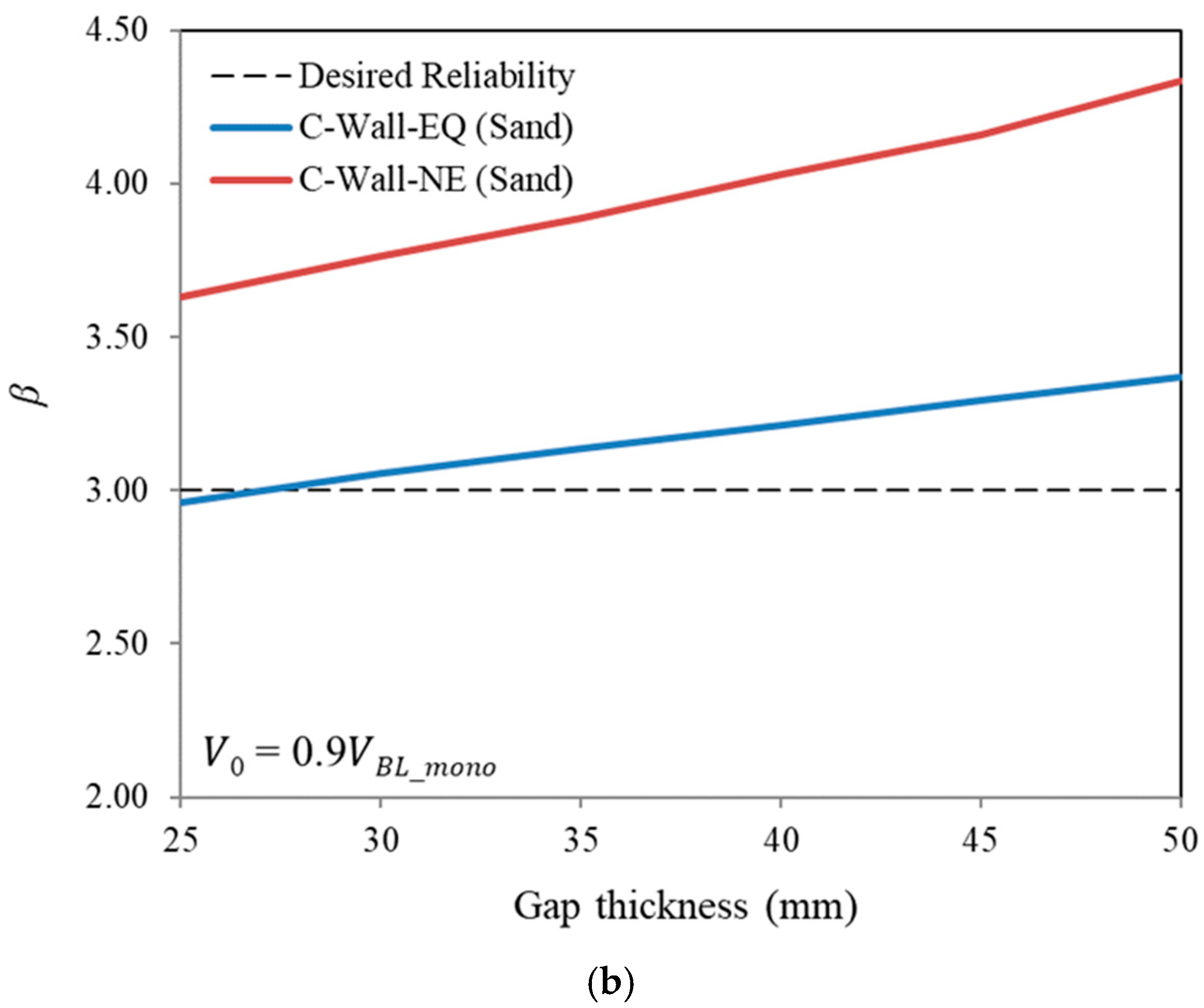
If the space between the two walls is filled with air rather than any material, it does not impact the safety performance of the composite wall system. This is illustrated in Figure 11a. However, Figure 11b demonstrates that when the gap is filled with a material such as sand, its thickness influences the reliability of the composite wall system. In this scenario, the reliability improves in a nearly linear fashion as the thickness of the filled gap increases. This is because a thicker-filled gap will cause the projectile to dissipate more energy before striking the rear wall. Due to this energy dissipation, the projectile will hit the rear wall with lesser velocity, leading to a higher ballistic threshold for the composite wall system and, consequently, greater system reliability.

7.3. Influence of the Thickness Ratio of Front to Rear Walls

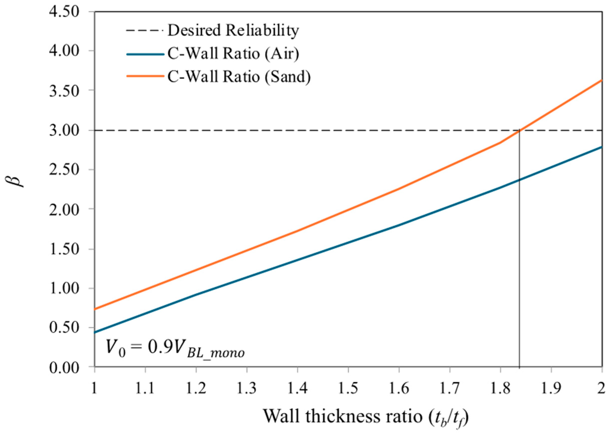
The ratio of front-to-rear wall thickness plays a crucial role in assessing the safety of composite wall systems against projectile impact. Figure 12 shows that with the increase in the front and rear wall ratios, there is a continuous increase in the reliability index. This occurs because, for a fixed front wall thickness, an increase in the thickness ratio leads to a thicker rear wall, which in turn raises the ballistic limit of the composite wall system. A higher ballistic limit enhances the safety margin for a given projectile impact velocity, thereby improving the system’s reliability. The figure also indicates that even when the thickness ratio is doubled, a composite wall system without a filling material in the gap has a reliability index below the target value of 3.0. However, when the gap is filled with sand, the required reliability is attained even at a thickness ratio of less than 1.85.

8. Conclusions

Key findings drawn from the investigation include:
  • The composite wall system provides a greater safety margin compared to a monolithic wall of the same total thickness and reinforcement. When no filling material was present between two walls of equal thickness, the target’s reliability was 49.2% higher than that of the one-piece concrete wall. Introducing infill materials such as compacted sand and recycled concrete aggregates (RCA) resulted in reliability improvements of 68.2% and 68.9% for the composite walls, respectively.
  • Compared to a monolithic wall of equal total thickness, RC targets constructed with walls of varying thicknesses showed markedly enhanced reliability—62% for an unfilled gap, 95% for a sand-filled gap, and 96% for a gap filled with RCA. These findings emphasize the enhanced synergistic behavior of double-wall targets, especially when the walls differ in thickness yet maintain the same total reinforcement as a monolithic RC wall.
  • When the filling material is lightweight (unit weight less than 1600 kg/m3), the present composite wall system with equally thick front and rear walls possesses a reliability value less than the minimum required level of safety. However, the reliability index is more than the minimum required value for unequal-thickness composite wall systems, even when the filling material is lightweight.
  • A thicker filled gap causes the projectile to dissipate more energy before striking the rear wall. As a result of this energy dissipation, the projectile impacts the rear wall at a reduced velocity, thereby raising the ballistic limit and enhancing the overall reliability of the composite wall system.
  • Even when the thickness ratio is double, the reliability of the composite wall system having no material between the gap has a reliability index less than the desired reliability of 3.0. However, if the gap is filled with sand, the desired reliability is achieved even when the ratio is much less than 2.0 (i.e., less than 1.85).
  • RC targets with unequal thickness double walls exhibit higher reliability than those with equal thickness. Using unequal thickness offers greater advantages, as the thinner front wall serves as a sacrificial layer, absorbing the initial impact. Damage to the front wall can be addressed with less complexity and expense, which contributes to greater maintainability and efficiency of the composite wall system.
  • This study is limited to the specific composite configurations, filler materials, projectile types, and single-impact scenarios tested. Future research should explore a wider variety of filler materials, different projectile shapes and velocities, and multiple-impact scenarios to assess the performance and reliability of these systems comprehensively. Such investigations would enhance the general applicability of the proposed methods and provide valuable guidance for designing cost-effective and resilient protective structures.

Author Contributions

Conceptualization, N.A.S. and H.A.; methodology, N.A.S.; validation, N.A.S. and H.A.; formal analysis and investigation, N.A.S.; resources, T.A. and Y.A.-S.; data curation, N.A.S. and H.A.; writing—original draft preparation, N.A.S. and H.A.; Writing—review and editing, T.A. and Y.A.-S.; visualization, N.A.S. and H.A.; supervision, T.A. and Y.A.-S.; funding acquisition, Y.A.-S. All authors have read and agreed to the published version of the manuscript.

Funding

This research was funded through Ongoing Research Funding program—Research Chairs (ORF-RC-2025-0400), King Saud University, Riyadh, Saudi Arabia.

Data Availability Statement

All data and models generated or used during the study appear in the article.

Acknowledgments

The authors gratefully acknowledge the funding received through Ongoing Research Funding program—Research Chairs (ORF-RC-2025-0400), King Saud University, Riyadh, Saudi Arabia.

Conflicts of Interest

The authors declare no conflicts of interest.

References

  1. Abbas, H.; Al-Dabaan, M.; Siddiqui, N.; Almusallam, T.; Al-Salloum, Y. Performance of reinforced concrete composite wall systems under projectile impact. J. Mater. Res. Technol. 2023, 23, 3062–3090. [Google Scholar] [CrossRef]
  2. Szydlowski, R.; Bednarz, K. Material and construction solutions of war shelters with the example of Hitler’s main headquarters in the Wolf’s Lair. Czas. Tech. 2018, 1, 87–101. [Google Scholar]
  3. Tao, Q.; Ren, P.; Shi, L.; Zhao, Z.; Tang, Y.; Ye, R.; Zhang, W.; Cui, J. Energy absorption and impact behavior of composite sandwich panels under high-velocity spherical projectile. Int. J. Impact Eng. 2022, 162, 104143. [Google Scholar] [CrossRef]
  4. Zhang, P.; Kong, X.; Wang, Z.; Zheng, C.; Liu, H.; Shi, G.; Dear, J.P.; Wu, W. High velocity projectile impact of a composite rubber/aluminium fluid-filled container. Int. J. Lightweight Mater. Manuf. 2021, 4, 1–8. [Google Scholar]
  5. Aktay, L.; Johnson, A.F.; Holzapfel, M. Prediction of impact damage on sandwich composite panels. Comput. Mater. Sci. 2005, 32, 252–260. [Google Scholar] [CrossRef]
  6. Gupta, N.K.; Iqbal, M.A.; Sekhon, G.S. Effect of projectile nose shape, impact velocity and target thickness on the deformation behavior of layered plates. Int. J. Impact Eng. 2008, 35, 37–60. [Google Scholar] [CrossRef]
  7. Siddiqui, N.A.; Khateeb, B.M.; Almusallam, T.H.; Abbas, H. Reliability of double-wall containment against the impact of hard projectiles. Nucl. Eng. Des. 2014, 270, 143–151. [Google Scholar] [CrossRef]
  8. Dancygier, A.N.; Katz, A.; Benamou, D.; Yankelevsky, D.Z. Resistance of double-layer reinforced HPC barriers to projectile impact. Int. J. Impact Eng. 2014, 67, 39–51. [Google Scholar] [CrossRef]
  9. Siddiqui, N.A.; Khateeb, B.M.; Almusallam, T.H.; Al-Salloum, Y.A.; Iqbal, R.A.; Abbas, H. Reliability of RC shielded steel plates against the impact of sharp nose projectiles. Int. J. Impact Eng. 2014, 69, 122–135. [Google Scholar] [CrossRef]
  10. Wu, H.; Fang, Q.; Gong, Z.M.; Peng, Y. Hard projectile impact on layered SFRHSC composite target. Int. J. Impact Eng. 2015, 84, 88–95. [Google Scholar] [CrossRef]
  11. Wu, H.; Fang, Q.; Peng, Y.; Gong, Z.M.; Kong, X.Z. Hard projectile perforation on the monolithic and segmented RC panels with a rear steel liner. Int. J. Impact Eng. 2015, 76, 232–250. [Google Scholar] [CrossRef]
  12. Feng, J.; Sun, W.; Liu, Z.; Cui, C.; Wang, X. An armour-piercing projectile penetration in a double-layered target of ultra-high-performance fiber reinforced concrete and armour steel: Experimental and numerical analyses. Mater. Des. 2016, 102, 131–141. [Google Scholar]
  13. Ebrahimi, H.; Ghosh, R.; Mahdi, E.; Nayeb-Hashemi, H.; Vaziri, A. Honeycomb sandwich panels subjected to combined shock and projectile impact. Int. J. Impact Eng. 2016, 95, 1–11. [Google Scholar] [CrossRef]
  14. Liu, C.; Zhang, Y.X.; Ye, L. High velocity impact responses of sandwich panels with metal fibre laminate skins and aluminium foam core. Int. J. Impact Eng. 2017, 100, 139–153. [Google Scholar] [CrossRef]
  15. Li, D.; Hou, H.; Chen, C.; Zhu, X.; Li, M.; Yi, Q. Experimental study on the combined damage of multi-layered composite structures subjected to close-range explosion of simulated warheads. Int. J. Impact Eng. 2018, 114, 133–146. [Google Scholar]
  16. Lai, J.; Yang, H.; Wang, H.; Zheng, X.; Wang, Q. Properties and Modeling of Ultra-High-Performance Concrete Subjected to Multiple Bullet Impacts. J. Mater. Civ. Eng. 2018, 30, 04018256. [Google Scholar]
  17. Wang, F.; Liu, J.B.; Bao, X.; Li, S.T.; An, Z.Y. Experimental study of the resistance of RC walls with different transverse reinforcements subjected to large-scale rigid projectile impacts. Eng. Struct. 2022, 251, 113558. [Google Scholar] [CrossRef]
  18. Choi, J.I.; Park, S.E.; Nguyễn, H.H.; Lee, Y.; Lee, B.Y. Resistance of hybrid layered composite panels composed of fiber-reinforced cementitious composites against high-velocity projectile impact. Compos. Struct. 2022, 281, 114993. [Google Scholar]
  19. Salhan, P.; Rashid, F.M. Effect of shape and obliquity of projectiles on the ballistic response of sandwich structures with carbon/epoxy face sheet subjected to low-velocity impact. Mater. Today Proc. 2022, 62, 6780–6787. [Google Scholar]
  20. Zhang, M.; Deng, G.; Du, Y.; Gao, W.; Sun, G.; Luo, D. Experimental investigation of the anti-penetration mechanism of UHPC reinforced with high-strength steel bars subjected to projectile impact. Constr. Build. Mater. 2023, 372, 130820. [Google Scholar]
  21. Remennikov, A.; Gan, E.C.; Ngo, T.; Netherton, M.D. The development and ballistic performance of protective steel-concrete composite barriers against hypervelocity impacts by explosively formed projectiles. Compos. Struct. 2019, 207, 625–644. [Google Scholar] [CrossRef]
  22. Shao, R.; Wu, C.; Su, Y.; Liu, Z.; Liu, J.; Xu, S. Numerical analysis on impact response of ultra-high strength concrete protected with composite materials against steel ogive-nosed projectile penetration. Compos. Struct. 2019, 220, 861–874. [Google Scholar] [CrossRef]
  23. Mahesh, V.; Joladarashi, S.; Kulkarni, S.M. A comprehensive review on material selection for polymer matrix composites subjected to impact load. Def. Technol. 2021, 17, 257–277. [Google Scholar] [CrossRef]
  24. Hazell, P.J. Armour: Materials, Theory, and Design; CRC Press: Boca Raton, FL, USA, 2022. [Google Scholar] [CrossRef]
  25. Karhankova, M.; Adamek, M.; Krstulović-Opara, L.; Mach, V.; Bagavac, P.; Stoklasek, P.; Mizera, A. Composites in Ballistic Applications Focused on Ballistic Vests—A Review. J. Compos. Sci. 2024, 8, 415. [Google Scholar] [CrossRef]
  26. Tamjid, M.I.; Abtew, M.A.; Kopot, C. Lightweight Textile and Fiber-Reinforced Composites for Soft Body Armor (SBA): Advances in Panel Design, Materials, and Testing Standards. J. Compos. Sci. 2025, 9, 337. [Google Scholar] [CrossRef]
  27. Toader, G.; Diacon, A.; Axinte, S.M.; Mocanu, A.; Rusen, E. State-of-the-art polyurea coatings: Synthesis aspects, structure–properties relationship, and nanocomposites for ballistic protection applications. Polymers 2024, 16, 454. [Google Scholar] [CrossRef]
  28. Safri, S.N.A.; Sultan, M.T.H.; Jawaid, M.; Jayakrishna, K. Impact behaviour of hybrid composites for structural applications: A review. Compos. Part B Eng. 2018, 133, 112–121. [Google Scholar] [CrossRef]
  29. Kevlar® Technical Guide. DuPont. Available online: https://www.dupont.com/content/dam/dupont/amer/us/en/safety/public/documents/en/Kevlar_Technical_Guide_0319.pdf (accessed on 24 September 2025).
  30. Yang, H.H. Kevlar Aramid Fiber; John Wiley & Sons: Hoboken, NJ, USA, 1993. [Google Scholar]
  31. Cunniff, P.M. Dimensionless parameters for optimization of textile-based body armor systems. In Proceedings of the 18th International Symposium on Ballistics, San Antonio, TX, USA, 15–19 November 1999; Technomic Publishing Co., Inc.: Lancaster, PA, USA, 1999; Volume 2, pp. 1303–1310. [Google Scholar]
  32. Duan, Y.; Keefe, M.; Bogetti, T.A.; Cheeseman, B.A. Modeling the role of friction during ballistic impact of a high-strength plain-weave fabric. Compos. Struct. 2005, 68, 331–337. [Google Scholar] [CrossRef]
  33. Das, S.; Jagan, S.; Shaw, A.; Pal, A. Determination of inter-yarn friction and its effect on ballistic response of para-aramid woven fabric under low velocity impact. Compos. Struct. 2015, 120, 129–140. [Google Scholar]
  34. Hani, A.A.; Roslan, A.; Mariatti, J.; Maziah, M. Body armor technology: A review of materials, construction techniques and enhancement of ballistic energy absorption. Adv. Mater. Res. 2012, 488, 806–812. [Google Scholar] [CrossRef]
  35. Zhang, H.; Zhang, J.; Chen, J.; Hao, X.; Wang, S.; Feng, X.; Guo, Y. Effects of solar UV irradiation on the tensile properties and structure of PPTA fiber. Polym. Degrad. Stab. 2006, 91, 2761–2767. [Google Scholar] [CrossRef]
  36. Wakatsuki, K.; Matsubara, M.; Watanabe, N.; Bao, L.; Morikawa, H. Effects of m-Aramid/p-Aramid blend ratio on tensile strength due to UV degradation for firefighter clothing fabrics and development of predictive equation for tensile strength. Polymers 2022, 14, 3241. [Google Scholar] [CrossRef]
  37. Phoenix, S.L.; Porwal, P.K. A new membrane model for the ballistic impact response and V50 performance of multi-ply fibrous systems. Int. J. Solids Struct. 2003, 40, 6723–6765. [Google Scholar] [CrossRef]
  38. Biradar, A.; Arulvel, S.; Kandasamy, J. Significance of ballistic parameters and nanohybridization in the development of textile-based body armor: A review. Int. J. Impact Eng. 2023, 180, 104700. [Google Scholar] [CrossRef]
  39. Luo, J.; Zhang, M.; Nie, J.; Liu, G.; Tan, J.; Yang, B.; Song, S.; Zhao, J.R. A deep insight into the structure and performance evolution of aramid nanofiber films induced by UV irradiation. Polym. Degrad. Stab. 2019, 167, 170–178. [Google Scholar] [CrossRef]
  40. Hussain, M.; Naqvi, R.A.; Abbas, N.; Khan, S.M.; Nawaz, S.; Hussain, A.; Zahra, N.; Khalid, M.W. Ultra-high-molecular-weight-polyethylene (UHMWPE) as a promising polymer material for biomedical applications: A concise review. Polymers 2020, 12, 323. [Google Scholar] [CrossRef]
  41. Luz, F.S.D.; Garcia Filho, F.D.C.; Oliveira, M.S.; Nascimento, L.F.C.; Monteiro, S.N. Composites with natural fibers and conventional materials applied in a hard armor: A comparison. Polymers 2020, 12, 1920. [Google Scholar] [CrossRef]
  42. Ding, L.; Gu, X.; Shen, P.; Kong, X. Ballistic limit of UHMWPE composite armor under impact of ogive-nose projectile. Polymers 2022, 14, 4866. [Google Scholar] [CrossRef]
  43. Zhu, Y.; Song, Y.; Wu, W.; Ma, J.; Fan, Z.; Wen, Y.; Xu, C.; Xia, M.; Da, W. Impact Response Features and Penetration Mechanism of UHMWPE Subjected to Handgun Bullet. Polymers 2024, 16, 1427. [Google Scholar] [CrossRef] [PubMed]
  44. Deitzel, J.M.; McDaniel, P.; Gillespie, J.W., Jr. High performance polyethylene fibers. In Structure and Properties of High-Performance Fibers; Woodhead Publishing: Cambridge, UK, 2017; pp. 167–185. [Google Scholar]
  45. Medvedovski, E. Alumina ceramics for ballistic protection. Part 1. Am. Ceram. Soc. Bull. 2002, 81, 27–31. [Google Scholar]
  46. Medvedovski, E. Alumina ceramics for ballistic protection. Part 2. Am. Ceram. Soc. Bull. 2002, 81, 45–50. [Google Scholar]
  47. Nael, M.A.; Dikin, D.A.; Admassu, N.; Elfishi, O.B.; Percec, S. Damage resistance of Kevlar® Fabric, UHMWPE, PVB multilayers subjected to concentrated drop-weight impact. Polymers 2024, 16, 1693. [Google Scholar] [CrossRef] [PubMed]
  48. Li, Q.M.; Reid, S.R.; Wen, H.M.; Telford, A.R. Local impact effects of hard missiles on concrete targets. Int. J. Impact Eng. 2005, 32, 224–284. [Google Scholar] [CrossRef]
  49. Almusallam, T.H.; Abadel, A.A.; Al-Salloum, Y.A.; Siddiqui, N.A.; Abbas, H. Effectiveness of hybrid-fibers in improving the impact resistance of RC slabs. Int. J. Impact Eng. 2015, 81, 61–73. [Google Scholar] [CrossRef]
  50. Almusallam, T.H.; Siddiqui, N.A.; Iqbal, R.A.; Abbas, H. Response of hybrid-fiber reinforced concrete slabs to hard projectile impact. Int. J. Impact Eng. 2013, 58, 17–30. [Google Scholar] [CrossRef]
  51. Nowak, A.S.; Collins, K.R. Reliability of Structures; CRC Press: Boca Raton, FL, USA, 2012. [Google Scholar]
  52. Siddiqui, N.; Abbas, H.; Almusallam, T.; Li, Q.M.; Al-Salloum, Y. Reliability assessment of steel-lined and prestressed FRC slabs against projectile impact. Appl. Sci. 2023, 13, 90. [Google Scholar] [CrossRef]
  53. Almusallam, T.; Al-Salloum, Y.; Alsayed, S.; Iqbal, R.; Abbas, H. Effect of CFRP strengthening on the response of RC slabs to hard projectile impact. Nucl. Eng. Des. 2015, 286, 211–226. [Google Scholar] [CrossRef]
  54. Siddiqui, N.A.; Al-Salloum, Y.A.; Almusallam, T.H.; Abadel, A.A.; Abbas, H. Reliability assessment of HFRC slabs against projectile impact. Int. J. Concr. Struct. Mater. 2018, 12, 58. [Google Scholar] [CrossRef]
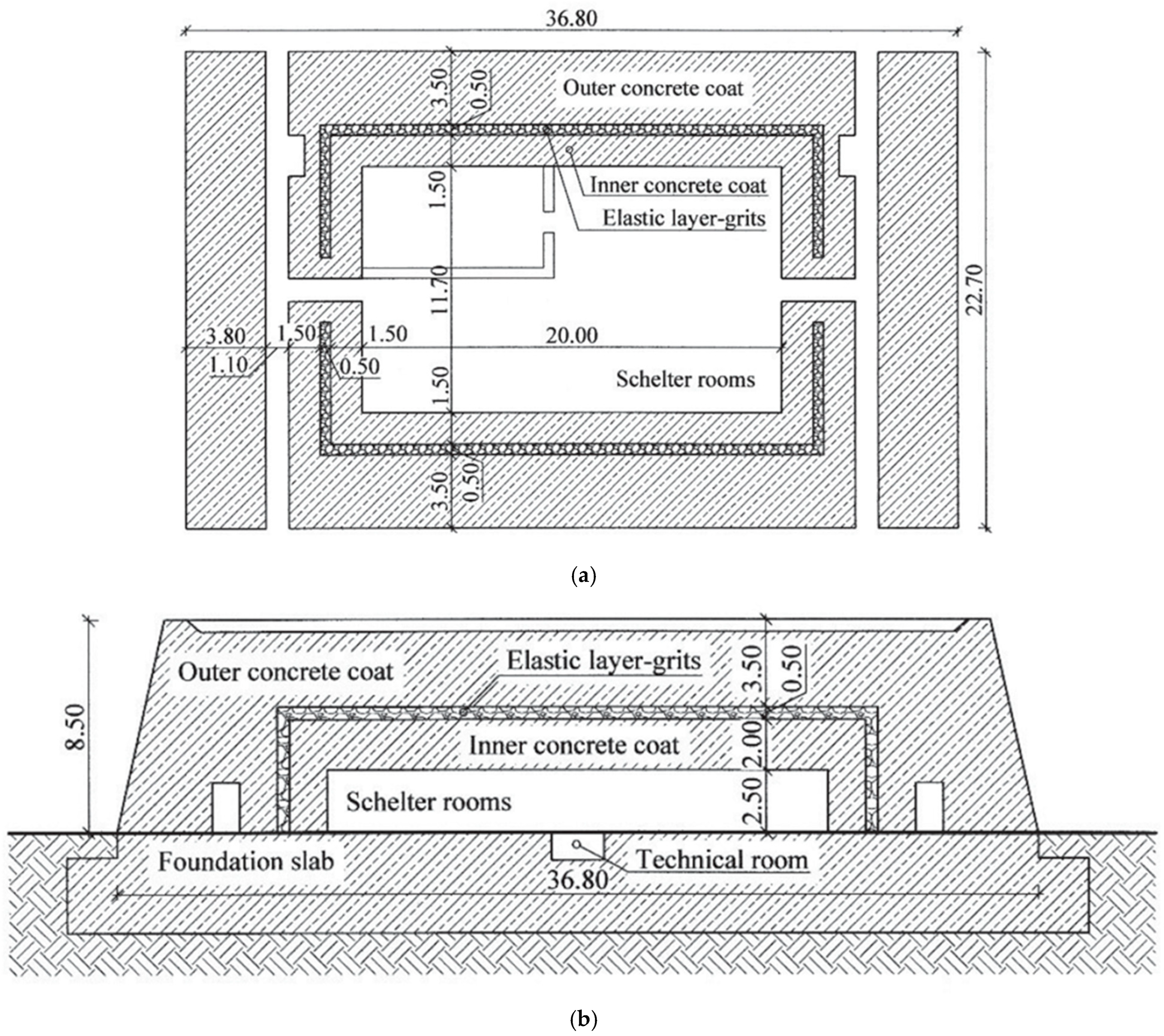
Figure 1. A composite bunker: (a) sectional plan; (b) vertical section (adapted from [2]). All dimensions are in m.
Applsci 15 11128 g001
Figure 2. Estimation of equivalent thickness: (a) composite wall system; (b) equivalent monolithic wall system (ϕx: bar size, s: bar spacing, t f and t b : thicknesses of the front and rear walls, t g : thickness of the filled gap).
Applsci 15 11128 g002
Figure 3. Test specimens: (a) wooden molds for casting wall specimens, (b) steel reinforcement skeletons for the slab specimen, (c) casting process of the specimens.
Applsci 15 11128 g003
Figure 4. Reinforcement details of the control specimen (monolithic RC wall).
Applsci 15 11128 g004
Figure 5. The reinforcement details in the composite wall specimen. (a) Equal-thickness composite wall specimen. (b) Non-identical thickness composite wall specimen.
Applsci 15 11128 g005
Figure 6. Illustrative diagrams of reinforced concrete (RC) wall specimens: (a) Group-1—Solid monolithic RC wall, (b) Group-2—Equal-thickness composite wall system, and (c) Group-3—Non-identical thickness composite wall system.
Applsci 15 11128 g006
Figure 7. Gas gun for testing wall specimens under projectile strike.
Applsci 15 11128 g007
Figure 8. Test chamber used for testing specimens under projectile impact.
Applsci 15 11128 g008
Figure 9. Failure patterns of (a) monolithic wall and (b) composite wall system (equal thickness, without infill) subjected to a projectile impact at a velocity of 92.5 m/s.
Applsci 15 11128 g009
Figure 10. Variation in reliability index with unit weight of filled material.
Applsci 15 11128 g010
Figure 11. Influence of gap thickness on the reliability of the composite wall system when: (a) no filling in the gap, and (b) the gap is filled with sand.
Applsci 15 11128 g011aApplsci 15 11128 g011b
Figure 12. The effect of wall thickness ratio on composite wall system reliability.
Applsci 15 11128 g012
Table 1. Estimation of Equivalent thickness and Ballistic limit.
Test Specimen t f
(mm)
t b
(mm)
Equivalent   Thickness   H O E (mm)Equivalent Steel Ratio, r (%)Experimental
Perforation Energy
[1]
Experimental Ballistic Limit (m/s)
[1]
Estimated Ballistic Limit (m/s)Error
Group-1: Solid Monolithic RC Wall
Wall-Monolithic75---19196961.810.4%
Group 2: Equal-thickness Composite Wall Systems
C-Wall-EQ-A37.537.588.90.74%25998177.34.6%
C-Wall-EQ-S37.537.592.70.70%27138285.1−3.8%
C-Wall-EQ-R37.537.593.00.70%27388385.6−3.1%
Group 3: Non-identical Thickness Composite Wall Systems
C-Wall-NE-A255091.50.72%26248182.6−2.0%
C-Wall-NE-S255099.20.65%396110098.31.7%
C-Wall-NE-R255099.70.65%396110099.30.7%
t f = front wall thickness; t b = rear wall thickness; M: Monolithic; EQ = Equal thickness; NE: Not Equal; A: Air; S: Compacted sand; R: Recycled aggregate.
Table 2. Variables with corresponding statistical values and probability distributions [54].
Variables Considered RandomNominal ValueBias FactorCoefficient of Variation (%)Distribution
Monolithic and Composite Walls
Concrete density, ρ c (kg/m3)25001.0510Log-normal distribution
Concrete strength, f c (MPa)301.110Log-normal distribution
Thickness of the concrete slab, H O E (mm), Variable1.05Gaussian distribution
Ratio of reinforcement, r (%)Variable1.110Gaussian distribution
Spacing of steel rebars, c r (mm)1000.95Log-normal distribution
Impacting Projectile
Projectile mass, M (kg)0.81.15Log-normal distribution
Diameter of projectile, d (mm)401.055Gaussian distribution
Velocity of impact, V 0 (m/s)Varied0.910Type I Extreme Value (EV-I) distribution
Table 3. Failure probabilities and reliability indices of composite wall systems.
Specimen ID * t f
(mm)
t b
(mm)
t g
(mm)
ρ f
(kg/m3)
V 0 / V B L _ m o n o P f β
Wall-Monolithic75---0.81.69 × 10−22.124
0.96.15 × 10−21.543
Composite walls made up of equal-thickness walls at 25 mm apart
C-Wall-EQ-A37.537.525 (Air)~ 00.87.44 × 10−43.177
0.94.70 × 10−32.597
C-Wall-EQ-S37.537.525 (Sand)16000.81.78 × 10−43.571
0.91.53 × 10−32.961
C-Wall-EQ-R37.537.525 (Recycled aggregate)17000.81.67 × 10−33.588
0.91.38 × 10−32.994
Composite walls made up of unequal-thickness walls at 25 mm apart
C-Wall-NE-A255025 (Air)~00.82.87 × 10−43.444
0.92.68 × 10−32.784
C-Wall-NE-S255025 (Sand)16000.81.60 × 10−44.159
0.91.40 × 10−43.633
C-Wall-NE-R255025 (Recycled aggregate)17000.81.47 × 10−54.179
0.91.19× 10−43.674
* M: Monolithic; EQ = Equal thickness; NE: Not Equal; A: Air; S: Sand; R: Recycled aggregate.
Disclaimer/Publisher’s Note: The statements, opinions and data contained in all publications are solely those of the individual author(s) and contributor(s) and not of MDPI and/or the editor(s). MDPI and/or the editor(s) disclaim responsibility for any injury to people or property resulting from any ideas, methods, instructions or products referred to in the content.