Article

The Influence of Temperature-Induced Deformation on Dynamic Characteristics of Novel Fabricated Track Beam-End Expansion Area at Long-Span Bridge: A Case Study in China

1
School of Civil Engineering, Beijing Jiaotong University, Beijing 100044, China
2
Beijing Key Laboratory of Track Engineering, Beijing Jiaotong University, Beijing 100044, China
3
Ningbo Municipal Railway Investment and Development Co., Ltd., Ningbo 315101, China
*
Author to whom correspondence should be addressed.
Appl. Sci. 2025, 15(20), 11117; https://doi.org/10.3390/app152011117
Submission received: 12 September 2025 / Revised: 13 October 2025 / Accepted: 14 October 2025 / Published: 16 October 2025
(This article belongs to the Section Civil Engineering)

Abstract

Prefabricated ballastless tracks are increasingly applied on long-span bridges, necessitating special attention to driving safety and comfort at weak connection areas like beam-end expansion joints. This study, based on the Ningbo-Xiangshan urban railway’s Xiangshangang sea-crossing bridge, establishes a refined train–track–bridge dynamic interaction model incorporating the beam-end expansion joint zone. The dynamic response characteristics of the train under temperature-induced deformation in beam-end expansion area conditions were explored. The research results show that the temperature-induced deformation of the end area of the long-span cable-stayed bridge has a greater impact on the vertical dynamic response of the train, but has a small impact on the lateral dynamic response of the train. Among them, the overall temperature rise and fall state of the long-span cable-stayed bridge has a significant impact on the dynamic response of the train. When a train passes through the beam-end expansion area, compared with the prefabricated track, the beam end area has a more obvious impact on the dynamic response of the train, but its scope of influence is only limited to the telescopic transition within the segment range. The temperature-induced deformation in the beam end area will have a greater impact on the dynamic response of the train, but the dynamic response of the train can still be controlled according to the relevant limits in the current standard. The results of this research can provide technical support for laying prefabricated tracks on large-span urban railway bridges, and provide technical reference for the optimization of expansion joints in the beam end area.

1. Introduction

By 2035, China’s national railway network is projected to reach approximately 200,000 km, forming a nationwide travel network with access times of 1, 2, and 3 h [1]. To achieve this goal, China has proposed prioritizing the planning and construction of urban rail transit systems in the Beijing–Tianjin–Hebei region, the Guangdong–Hong Kong–Macao Greater Bay Area, and the Yangtze River Delta [2]. Urban rail transit in China is still in its early stages. In regions with numerous mountains and rivers, developing long-span urban rail bridges has become a growing trend. Prefabricated tracks, with advantages such as high factory-controlled quality, high precision, high smoothness, and superior passenger comfort, have become the development orientation for laying track structures on urban rail bridges [3]. As the spans of urban rail bridges increase, beam-end expansion devices have become necessary structures for long-span urban rail bridges. Due to the significant structural differences between the beam-end expansion device and the track on a bridge, as well as the lack of a substructure for support, the beam-end expansion device is considered a weak point in bridge-based railway systems, drawing widespread attention from researchers. Wang et al. [4,5,6,7] and other Chinese and international scholars have conducted simulation analyses on the performance of beam-end expansion devices. Li et al. [8,9,10,11] carried out extensive research on the service performance of beam-end expansion devices. Guo et al. [12] studied rail expansion joints and beam-end expansion devices on bridges, optimized their structures, proposed layout schemes, and also numerically simulated and validated the performance of beam-end expansion devices. Regarding the Wuhu Yangtze River Railway and Highway Bridge on the Shangqiu–Hefei–Hangzhou High-Speed Railway, Zhang [13] for the first time had the rail expansion joint for ballasted tracks on a high-speed railway integrated with a beam-end expansion device, forming into a unified system, validating the practical engineering application value of beam-end expansion devices. Based on the Ganzhou Ganjiang Grand Bridge on the Changji–Ganzhou Passenger Dedicated Line, the world’s first long-span cable-stayed bridge with ballastless tracks, Zheng et al. [14], conducted theoretical and experimental research on the deformation adaptability of ballastless tracks on a long-span cable-stayed bridge. This study revealed the deformation characteristics of an integrated system of a long-span cable-stayed bridge and ballastless tracks. Hou et al. [15], using a long-span concrete arch bridge as a prototype, investigated the impact of changes in the parameters of bridge expansion devices for ballasted tracks on the dynamic responses induced by trains. Xiao et al. [16,17] established an accurate model linking the temperature field of the main girder to the displacement of expansion joints, enabling precise and reliable performance prediction of expansion joints in ballasted track bridges. Zhang et al. [18,19,20] and many other researchers optimized the parameters of beam-end expansion areas to achieve a better track structure and dynamic responses of trains. Meng [21], based on the data measured from the inspection of ballastless tracks on long-span bridges, analyzed the performance of structures in the beam-end expansion areas on two sides of the main bridge. The vertical vibration acceleration of the train’s axle box was found to be most affected by the track irregularity on the bridge. Lin et al. [22], through field tests, surveyed the stiffness variation in the beam-end expansion device areas on the bridge and analyzed the distribution rules of beam-end strain. Zhang [23], investigated the dynamic response of a coupled ballastless track-bridge model under long-term concrete shrinkage and creep effects. Existing research on the beam-end expansion adjustment areas of bridges primarily focuses on ballasted track bridges, wherein many long-span bridges are designed on high-speed railway lines. Few studies involved long-span urban rail bridges laid with prefabricated ballastless tracks, particularly in the beam-end expansion adjustment areas. This study surveyed a newly planned and designed urban rail cable-stayed bridge with prefabricated ballastless tracks and a main span of 688 m. The focus is on exploring the influences of thermal deformation in long-span urban rail bridges on the new prefabricated track and its expansion device transition area at beam ends.

2. The Refined Model for the Prefabricated Track and Beam-End System

Based on the theory of multi-body dynamics and the finite element method, a spatially coupled dynamic analysis model was established for the urban A-type train, prefabricated ballastless track, and long-span cable-stayed bridge using finite element software and self-developed programs.

2.1. Finite Element Model of the Long-Span Cable-Stayed Bridge

The long-span cable-stayed bridge was designed utilizing a combined steel box girder cable-stayed bridge structure, with a span layout of (82 + 262 + 688 + 262 + 82) m, where the main span was 688 m. The total length of the bridge extended to 1376 m. The finite element model of this bridge is shown in Figure 1.
Compared with ordinary simply supported beam bridges and continuous beam bridges, the finite element analysis model of cable-stayed bridges requires not only the modeling of rails, beams, and piers but also the inclusion of towers and stay cables, which undoubtedly increases the modeling workload. Since cross beams are installed on the main continuous girder to anchor the stay cables, the cross-sectional form of the main continuous girder becomes more complex. Additionally, considerations such as the connections between the tower, stay cables, and main continuous girder further complicate the finite element analysis modeling process for prefabricated tracks on cable-stayed bridges.
In this study, the rail is treated as a finite-length beam longitudinally supported on an elastic foundation, capable of bearing both tension and compression with equal and constant stiffness. The longitudinal forces at the two ends of a rail node are balanced by the longitudinal resistance of the track, and the displacement difference between two adjacent nodes is proportional to the released longitudinal force of the rail element. When simulating concrete solid components, appropriate simplifications can be made within acceptable error margins. The deformation of all concrete solid components in the bridge complies with the plane-section assumption.
All stay cables can only withstand tension, not compression. One end of each stay cable is hinged to the tower, while the other end is hinged to nodes on both sides of the bridge. Due to the low height and high stiffness of the abutment, its longitudinal flexibility is neglected, and the support foundation at this location is assumed to have sufficiently large stiffness. It is assumed that movable supports do not transmit longitudinal forces. The sediment-covered portion at the bottom of the pier is considered fixed to the foundation.
Restrict boss are treated as longitudinal spring constraints between beams and slabs, located either at the mid-span or end of the slab. Their displacement resistance characteristics differ from those of the fastening system, acting as linear springs without ultimate resistance limits. As relative displacement increases, the constraint resistance increases proportionally. The frictional resistance between the track slab and the beam surface is the product of the track weight and the friction coefficient beneath the slab. When train loads are present, the live load effect of the train must be considered.
For simplification, the frictional resistance is treated as a longitudinal spring constraint under the fastener nodes. As long as longitudinal relative displacement exists between the track slab and the beam surface, this frictional force is present and remains constant. The track slab, located on the beam surface with a small volume, is significantly affected by temperature variations. A temperature gradient exists between the track slab and the girder, and its daily temperature variation can be slightly greater than that of the concrete bridge.

2.2. Beam-End Expansion Area Model

In this study, the on-bridge track structure consists of the following components from bottom to top:
Base slab: Made of C60 concrete, modeled with solid elements, connected to the bridge deck via reinforcing bars with tie constraints.
Restrict boss (500 mm diameter): Cast integrally with the base slab, modeled with solid elements and tie constraints.
Rubber pads (stiffness: 0.05 N/mm3): Covering the base slab and restrict boss, modeled with solid elements. The contact relationship is defined with vertical and horizontal friction coefficients set to 0.7 [24].
Track slab (4900 mm × 2500 mm × 200 mm): Modeled with solid elements and tie constraints.
Fastening system: Modeled with spring elements as elastic links.
Rail: Modeled with beam elements as elastic connection.
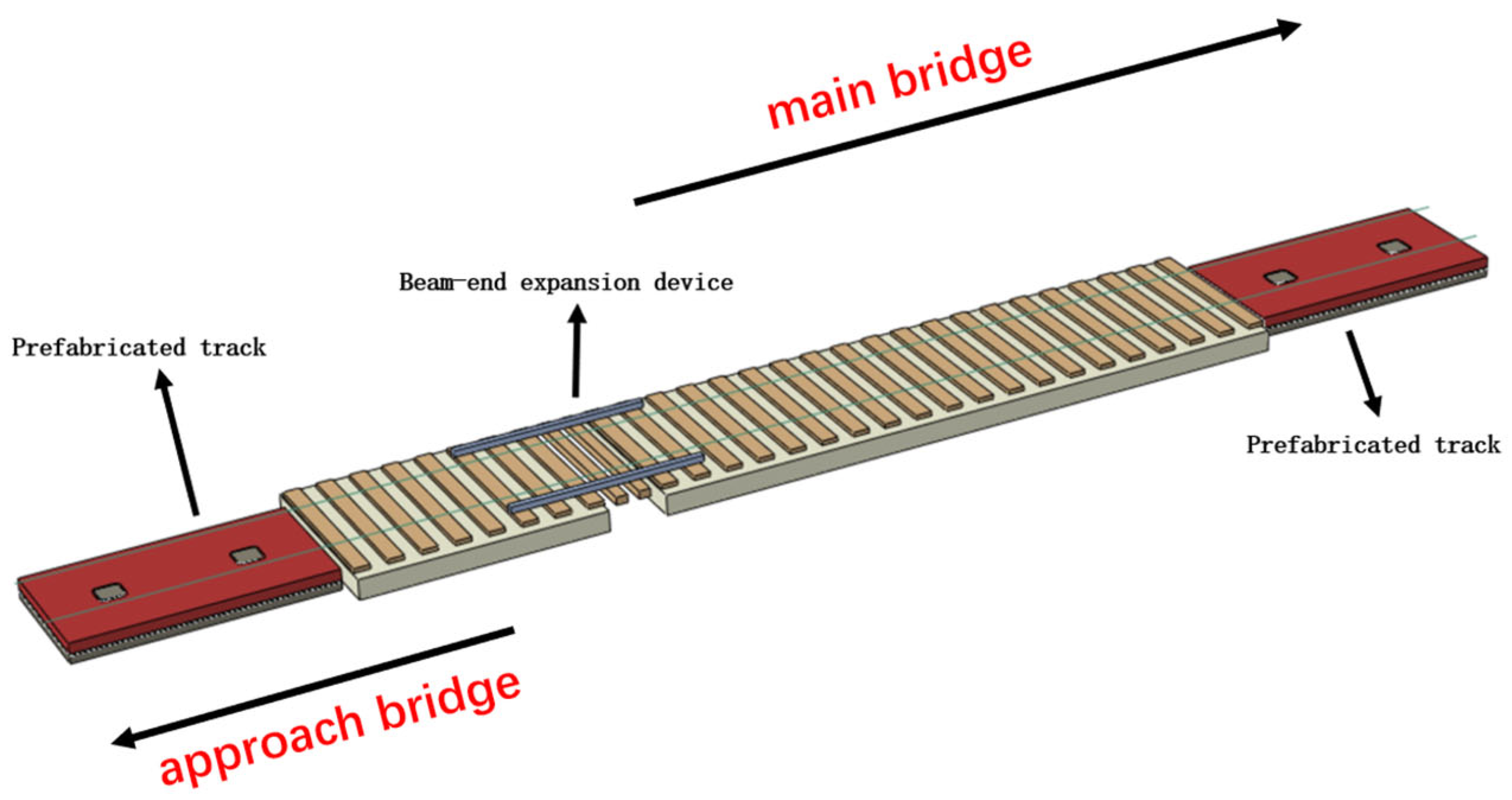
The overall structure, shown in Figure 2, the detailed parameters are specified in Table 1, forms a novel prefabricated slab track system, as specified by the bridge design authority [3].
For the Xiangshan Port Cross-Sea Bridge, BWG rail expansion joints are arranged in the girder joints between the main bridge and a pair of adjacent rigid-frame bridges on both sides, with a total length of 17.55 m and an expansion range of ±100 mm at the beam end of the approach bridge and ±500 mm at the beam end of the main bridge. Limited by the distance of 3.8 m between rails, the scissor jacks of the expansion joints are positioned vertically. The pointed end of the rail expansion joint is arranged on the main bridge, while the basic rail end is placed on the rigid-frame bridges on both sides and across the gap between beams. The rail expansion joint employs a cast-in situ sleeper-embedded track bed with a base beneath it. The widths of this expansion joint track bed and base are both 3.25 m. In other non-adjustment areas of the pair of adjacent rigid-frame bridges on both sides, prefabricated tracks are employed, where the track bed and base are isolated using geotextile and have a consistent width of 2.8 m.
In this study, a locally refined model for the beam-end expansion area was established, focusing on the total length of the beam-end expansion device and the length of one slab of the prefabricated track structure on each side (left and right). The beam-end expansion device would displace due to temperature variation. Compared to the time required for temperature variation, the time taken for a train to pass can be neglected. Thus, the environmental temperature was deemed constant. Namely, the beam-end expansion device would not expand or contract due to temperature effects. The gap between beams and the spacing between sleepers would remain unchanged, allowing neglect of the influence of the scissor jacks on the beam-end expansion device. Longitudinal beams, movable sleepers, fixed sleepers, and series of sleepers were all simulated using beam elements, while fasteners were simulated using spring-damping elements [25]. The finite element model of the beam-end expansion area is presented in Figure 3.

2.3. Vehicle–Rail–Bridge Coupling Dynamic Model

The vehicle structure primarily consists of the train body, bogie frame, wheelsets, and suspension systems. Among these components, the vibrations of the train body and bogie frame are damped by the primary and secondary suspensions, resulting in significant attenuation of high-frequency energy. Thus, they can be treated as rigid bodies. For the wheelsets, a rigid-body model is adopted to reflect their rigid-body motion in a floating coordinate system.
In the train system, the train body, bogie frame, and wheelsets are modeled using lumped mass elements. The secondary suspension between the train body and bogie, the primary suspension between the bogie and wheelsets, and the coupler effects between adjacent train bodies are all simulated with linear spring-damper units. The entire vehicle model has a total of 42 degrees of freedom.
Based on this framework, the equations of motion are derived and assembled using d’Alembert’s principle, yielding the dynamic control equations of the multi-rigid-body vehicle structure, as shown in equation:
M c c 0 0 0 M b b 0 0 0 M w w u ¨ c u ¨ b u ¨ w + C c c C c b 0 C c b C b b C b w 0 C w b C w w u ˙ c u ˙ b u ˙ w + K c c K c b 0 K c b K b b K b w 0 K w b K w w u c u b u w = 0 0 F w r ,
where M, K and C represent the mass, stiffness, and damping matrices, respectively; u ¨ , u ˙ and u denote the acceleration, velocity, and displacement vectors, respectively. The subscripts c, b and w correspond to the car body, bogie frame, and wheelset, respectively.
To obtain more accurate load excitation, it is essential to account for the broadband vibration characteristics of the vehicle–track coupled system. Hence, building upon the multi-rigid-body vehicle model, wheelset flexible vibration characteristics are introduced, evolving the traditional multi-rigid-body vehicle model into a rigid–flexible coupled vehicle model [26].
The flexible wheelset model must solve for the minute elastic deformations of wheels under inertial effects from their own rotation and gyroscopic effects. To achieve this, the floating frame of reference method and modal synthesis method are integrated to solve for the wheelset’s flexible deformations under complex loading conditions. Consequently, the position vector rk(0) of any point K on the wheelset in the global coordinate system can be expressed as:
r k ( 0 ) = r 1 ( 0 ) + A w p k ( 1 ) = r 1 ( 0 ) + A w ρ k ( 1 ) + d k ( 1 ) ,
where r1(0) is the radial vector of the floating coordinate system CS1 relative to the global coordinate system CS0, obtainable through rigid-body dynamics; pk(1) denotes the radial vector of point K on the wheelset in the CS1 coordinate system; represents the transformation matrix from the floating coordinate system CS1 to the global coordinate system CS0; ρk(1) and dk(1) are the radial vector and flexible deformation of point K relative to CS1 in its undeformed state, respectively; here, dk(1) can be computed via the modal superposition method based on the finite element method:
d k ( 1 ) = Φ w p w t ,
where Φ w is the normal mode matrix (i.e., the modal matrix) of the flexible wheelset; while p w t is the column vector of normal coordinates for the wheelset.
For a rotating flexible body, the column vector of normal coordinates p w t is given by:
p ¨ w + C + 2 Ω J ˜ p ˙ w + K ˜ Ω 2 E ˜ p w = Q p + Ω 2 L ˜ ,
where K ˜ is the modal stiffness matrix of the wheelset system, which can be expressed as a diagonal matrix of squared modal eigenvalues; J ˜ is the gyroscopic matrix related to the gyroscopic effects induced by the rotation of the wheelset; E ˜ and L ˜ are the centrifugal matrices related to the centrifugal effects during wheelset rotation; Ω denotes the rotational speed of the wheels; Q p is the generalized load vector of external forces in the modal domain.
It is noteworthy that the aforementioned equations of motion are derived in the conventional Lagrangian coordinate system, which requires the external forces to act at fixed positions. However, in reality, as the wheels rotate, both the contact locations on the wheelset and the wheel-rail forces continuously evolve. This implies that position vectors like ρk(1) in Equation (3) require redefinition, significantly increasing computational cost. Thus, leveraging the transformation relationship between Lagrangian and Eulerian coordinate systems, the flexible motion equations of the rotating wheelset can be expressed as:
q ¨ w f + C ˜ + 2 Ω G ˜ q ˙ w f + K ˜ + Ω 2 J ˜ J ˜ T G ˜ G ˜ T E ˜ q w f = Q q + Ω 2 L ˜ ,
where q w f is the modal normal coordinate vector in the Eulerian coordinate system; C ˜ is the damping matrix of the wheelset system, described using a Rayleigh damping model; K ˜ is the diagonal matrix composed of squared modal frequencies of the flexible wheelset; G ˜ is the gyroscopic matrix; H ˜ = J ˜ J ˜ T G ˜ G ˜ T E ˜ represents centrifugal forces generated by convective acceleration and flexible deformation; L ˜ denotes constant centrifugal forces. Notably, the matrices K ˜ , G ˜ , J ˜ , E ˜ and L ˜ above are all time-invariant (independent of time variable t) and can be precomputed prior to numerical integration.
At this stage, coupling Equation (5) with the rigid-body equations of motion 1 yields the rigid–flexible coupled dynamics equations of the vehicle system.
In most vehicle–track coupling dynamics problems, the wheel-rail contact patch is typically assumed to be elliptical, and the computationally efficient Hertzian contact model is adopted. However, when the wheel-rail contact patch deviates from the standard elliptical shape, the normal stress distribution within the contact patch no longer follows an ellipsoidal or paraboloidal pattern. Moreover, the wheel-rail contact may exhibit two-point or even multiple-point contact scenarios. In such cases, continued use of the Hertzian contact model would introduce significant computational errors that are difficult to quantify.
Therefore, this study first determines the spatial contact positions between wheel and rail using the trace method. Subsequently, the Kik-Piotrowski model is employed to calculate the wheel-rail normal force, while the FASTSIM algorithm is used to solve for the tangential forces. The resulting wheel-rail normal force is expressed as:
x f = x b 2 R g ( y ) ,
N = y r y l x f x f p ( x , y ) d x d y = π E δ 2 1 μ 2 y r y l x f x f x f 2 ( y ) x 2 d x d y y r y l x f x f x f 2 ( y ) x 2 x 2 + y 2 d x d y ,
where y l and y r represent the left and right boundaries of the contact patch; x f and x b represent the front and rear boundaries of the contact patch; P denotes the normal contact pressure at the contact origin.
The Fastsim algorithm is employed to simulate the wheel-rail tangential adhesion-creep behavior, which effectively captures the adhesion-creep distribution characteristics under complex adhesion conditions while maintaining high computational efficiency. The Fastsim algorithm assumes the wheel-rail contact patch to be a standard ellipse, which is consistent with the modified contact patch characteristics obtained using the K-P model for calculating wheel-rail normal forces. Based on this assumption, the algorithm solves for the wheel-rail tangential forces using the finite difference method.
According to Kalker’s simplified theory, it is assumed that the elastic displacement at any point within the wheel-rail contact zone depends solely on the surface stress applied at that point. This allows the contact bodies to be modeled using a simple Winkler elastic foundation, significantly reducing computational complexity while maintaining solution accuracy. The resultant wheel-rail tangential forces are given by:
F x = C p x ( x , y ) d x d y = 8 a 2 b 3 L 1 ξ x F y = C p y ( x , y ) d x d y = 8 a 2 b 3 L 2 ξ y π a 3 b φ 4 L 2 ,
where F x and F y represent the resultant tangential forces along the longitudinal and lateral directions within the wheel-rail contact patch, respectively; a and b denote the semi-major axis and semi-minor axis of the contact ellipse, determined by the equivalent elliptical parameters obtained during the wheel-rail normal force calculation; L is the compliance coefficient in the K-P model; ξ x , ξ y are the longitudinal and lateral creepages of the wheel-rail system, respectively; x and y indicate the distances from any point in the contact patch to the rotation center.
In the Fastsim algorithm based on Kalker’s simplified theory, the elliptical contact patch is discretized into strips along the direction of vehicle movement during numerical computation, with each strip further divided into rectangular elements along the lateral direction. Under the assumption of zero stress at the leading edge of the contact patch, the tangential stress at the center of each grid cell is obtained through backward difference step-by-step calculation. The recursive formula is given by:
Δ q t x = ξ x L 1 ξ φ y L 1 Δ x Δ q t y = ξ y L 2 + ξ φ ( 2 x Δ x ) 2 L 2 Δ x ,
The solution proceeds sequentially from the leading edge to the trailing edge of the wheel-rail contact patch, thereby obtaining the tangential stress distribution across the entire contact area, which is then used to calculate the resultant wheel-rail tangential forces.
A “plug-in” method is employed to integrate the established rigid–flexible coupled vehicle model, track structure model, and wheel-rail contact model into a vehicle–track coupled system submodel for broadband vibration analysis. The dynamic equations of the system can be expressed as:
M c c 0 0 0 M r r 0 0 0 M s s u c u r u s + C c c C c r 0 C r c C r r C r s 0 C s r C s s u ˙ c u ˙ r u ˙ s + K c c K c r 0 K r c K r r K r s 0 K s r K s s u c u r u s = F w r F r w 0 ,
where M, C and K represent the mass matrix, damping matrix, and stiffness matrix, respectively; the subscripts c, r and s denote the vehicle, rail, and track structure components; F w r and F r w are the wheel-rail dynamic interaction forces.

2.4. Model Validation

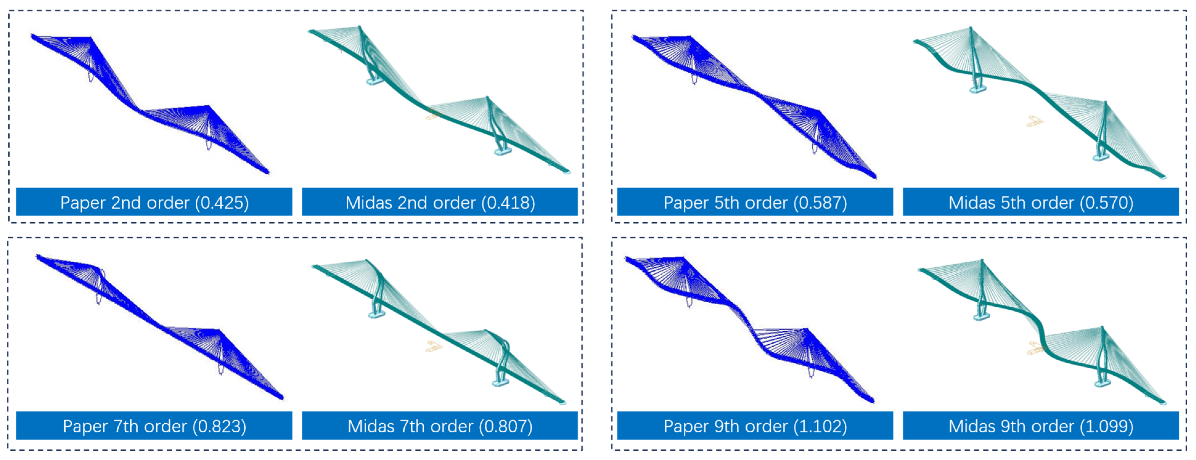
Based on previous research on the application of prefabricated tracks in long-span bridges [27], this study incorporates expansion joint devices at beam ends. To ensure accuracy, the first ten vibration modes and frequencies of the established finite element model were calculated using the multiple Ritz vector method. The results were then compared with the vibration modes and frequencies from the MIDAS model provided by the design unit. Based on previous research experience [28], to validate the correctness of the model in this study, it is necessary to ensure that the first ten mode shapes from the modal analysis of the model in this paper match those of the model provided by the design institute in terms of their manifestation. Additionally, the frequency error between corresponding mode shapes of the two models must be less than 10%. Notably, the design unit’s MIDAS model does not include expansion joint devices at beam ends, whereas the model in this study does. A comparison of the modal parameters is presented in Table 2, while the vibration mode shapes are compared in Figure 4.
As shown above, compared to the existing bridge model without beam-end expansion joints, the model proposed in this study exhibits similar vibration modes and frequencies. This indicates that the expansion joint devices have limited influence on the modal analysis of long-span bridges. Furthermore, when compared to the natural frequencies provided by the design unit, the average error of the first ten natural vibration frequencies calculated using the model in this study is less than 3%. This demonstrates the high accuracy of the finite element model developed in this research, providing reliable assurance for subsequent calculations.

3. Analysis of the Train-Rail-Bridge Dynamic Performance at Beam Ends Under Complex Temperature Load Conditions

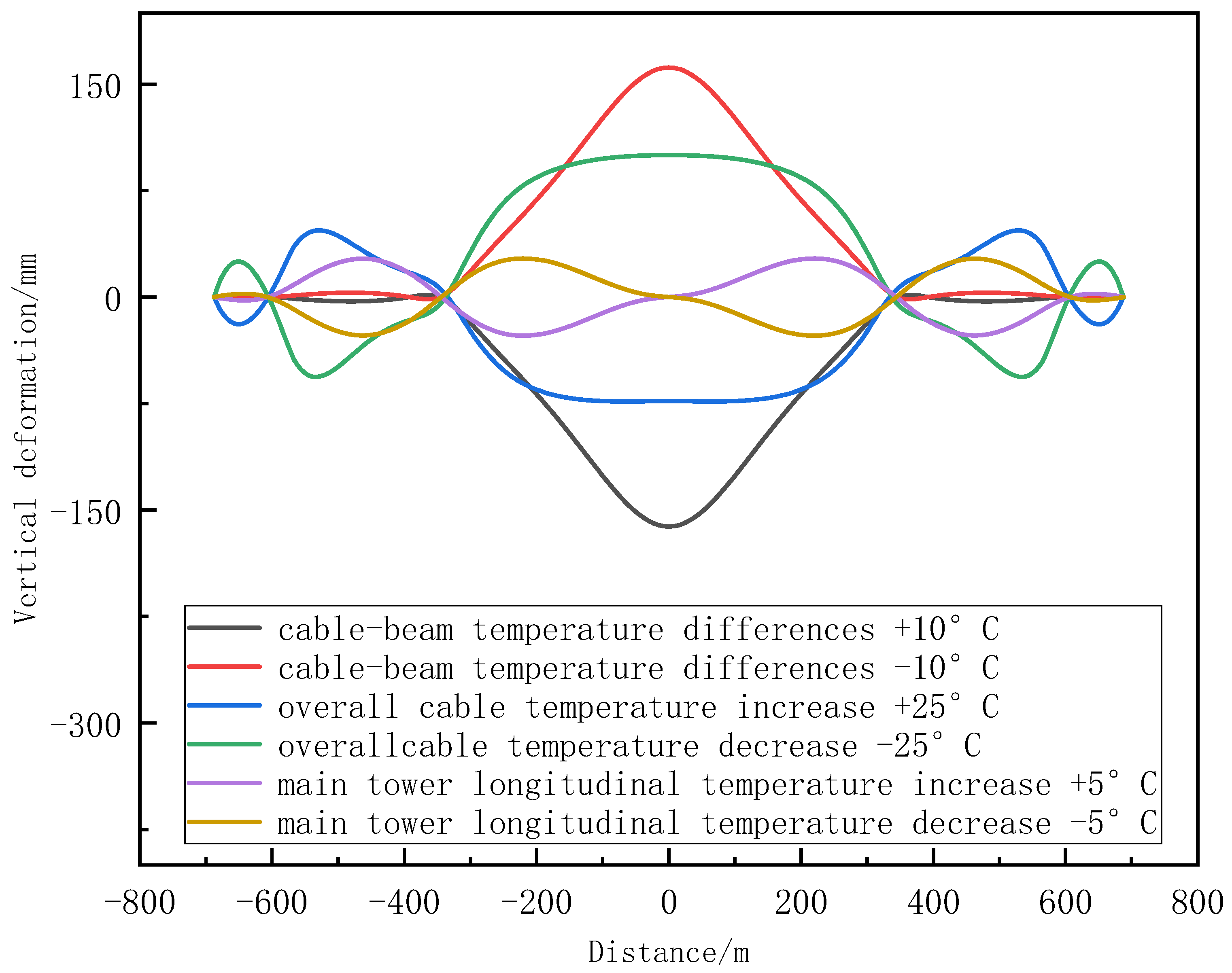
The massive structure and flexible system of long-span cable-stayed bridges are inevitably affected by the complex and variable environment, especially by the long-term effect of environmental temperature. Deformations of the bridge deck caused by temperature changes are significant, posing challenges to the adaptability of prefabricated tracks on the bridge. When the cable-stayed bridge is affected by temperature variations, the bridge deck will deform vertically, longitudinally, and laterally due to the thermal expansion and contraction of the steel cables and bridge components, thus driving the beam joints and deck panels to expand and contract. When subjected to temperature loads, the steel cables will either elongate or shorten, affecting the vertical deformation of the main span of the bridge. The two main towers of the cable-stayed bridge may also expand or contract due to temperature variations, influencing the deformation of the main span. The bridge typically exhibits significant deformation amplitude and curvature. Due to the direct contact between the track and the bridge, the bridge deformation can lead to additional track irregularities compared to other substructures, with particularly obvious deformations at beam ends. Therefore, it is essential to systematically reassess the dynamic impact of deformations at the beam ends of a long-span bridge on the train operating comfort.

3.1. Load Conditions

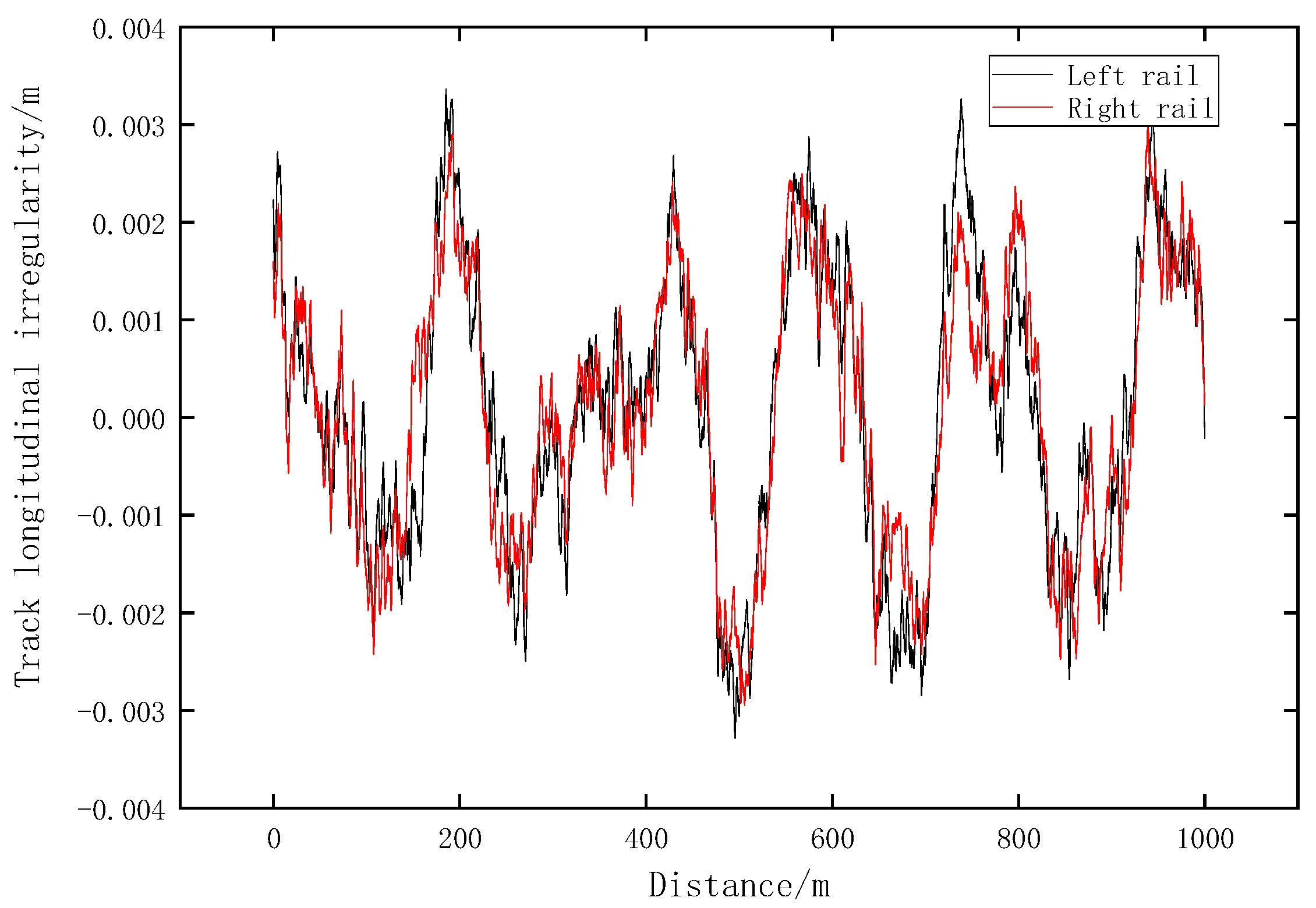
For the urban railway cable-stayed bridge with a main span of 688 m, the cumulated effects of random track irregularities and bridge deflection caused by temperature loads were treated as excitations acting on the track in the beam-end area, forming six working conditions used in this study. The random track irregularities consist of lateral and vertical random irregularities generated from the American five-level irregularity spectrum. The temperature loads include cable-beam temperature differences of +/−10 °C, overall temperature variations of +/−25 °C, and longitudinal temperature variations of +/−5 °C in the main tower. The random track irregularities are shown in Figure 5 and Figure 6. The temperature-induced deformation curve of the cable-stayed bridge is depicted in Figure 7.

3.2. Dynamic Response Analysis of Train in the Beam-End Expansion Area

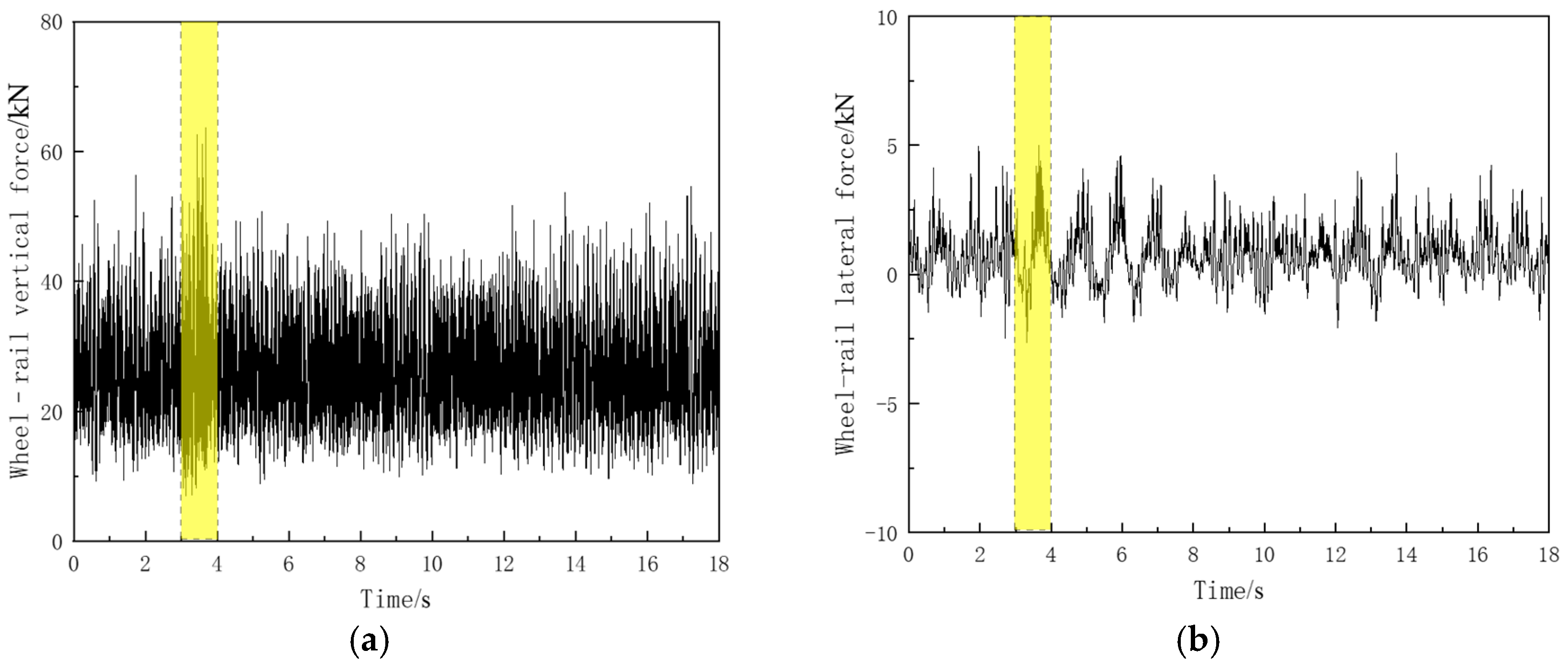
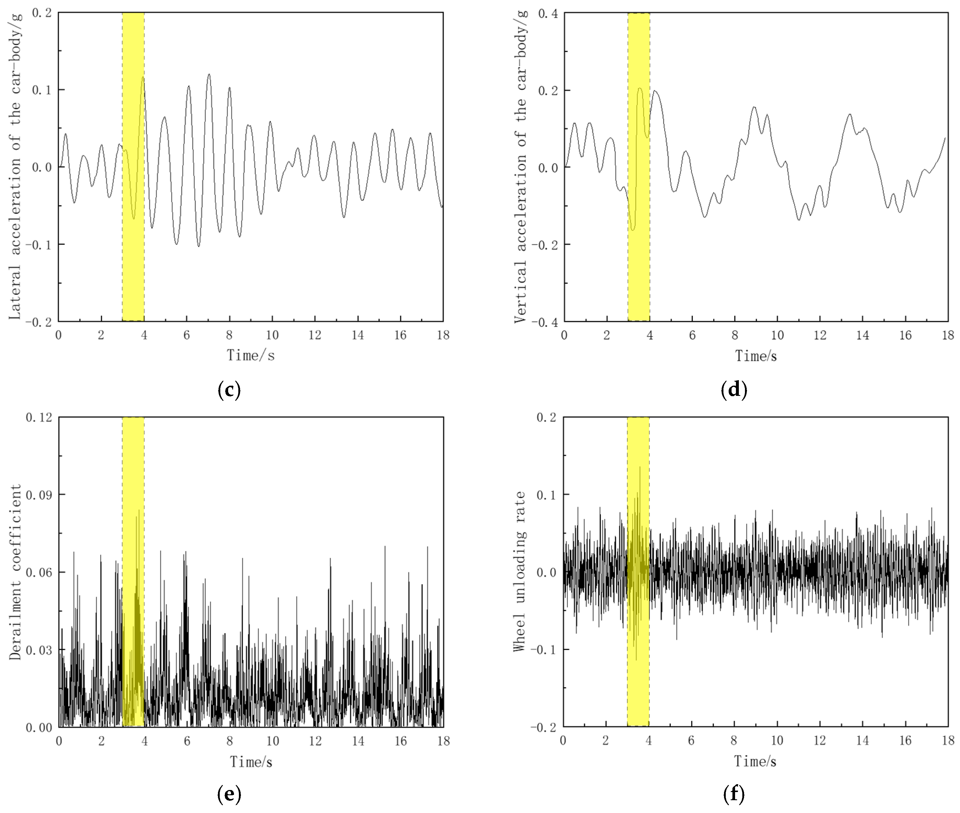
To analyze the dynamic response of the train passing through the beam-end expansion area, the refined analytical model established in Section 1 was only added with random irregularity as an excitation, without considering the bridge deformation caused by temperature changes. The beam-end expansion area is highlighted with a yellow box in Figure 8.
When a train passed through the beam ends of the long-span urban cable-stayed bridge at a speed of 160 km/h, the vertical dynamic response of the train peaked significantly provided that the bridge deck was not subjected to temperature-induced deformation. At this time, the maximum vertical force between the wheel and rail reached 66.9 kN, and the maximum vertical acceleration of the train body was 0.21 m/s2. Compared to the vertical dynamic response of the train, the lateral dynamic response of the train body in the beam-end area did not exhibit a pronounced peak; the maximum lateral force between the wheel and rail was 5.1 kN, while the peak lateral acceleration of the train body was 0.23 m/s2. Under the effects of the wheel and rail, the derailment coefficient and wheel load reduction rate in the beam-end area also showed noticeable peak values, with the maximum derailment coefficient being 0.084 and the maximum wheel load reduction rate reaching 0.13.

3.3. The Impact of Temperature-Induced Deformation in the Beam-End Expansion Area on the Train’s Dynamic Response

When the temperature changed, irregularities caused by the temperature-induced deformation of the cable-stayed bridge were superimposed on random irregularities as excitations. Then, an analysis was made of the wheel-rail vertical force, wheel-rail lateral force, wheel axle lateral force, derailment coefficient, wheel load reduction rate, train lateral acceleration, train vertical acceleration, and stability of the train, as shown in Table 3, when an urban A-type train passed through the beam-end area of the long-span cable-stayed bridge at a speed of 160 km/h under six working conditions, respectively. The bridge is located in a warm-temperate continental semi-humid monsoon climate zone with mild weather and four distinct seasons. Meteorological data shows an annual average temperature above 15 °C, with extreme highs of 43 °C and lows of −18 °C, thus establishing six working conditions: cable temperature differences of +/−10 °C, overall temperature variations of +/−25 °C, and longitudinal temperature changes of +/−5 °C in the main tower. Compared with temperature-induced deformation, the effects of long-term creep, shrinkage, or combined wind effects on vehicle dynamic response in the beam-end expansion area are negligible. Thus, this chapter considers only temperature variation.
Compared to the scenario where only random irregularities were considered as excitations, both the vertical acceleration of the train body and the wheel-rail vertical force in the beam-end area of the long-span cable-stayed bridge increased significantly under the said six temperature load conditions. Notably, under the condition of overall temperature decrease, the wheel-rail vertical force and the train body’s vertical acceleration changed the most, by 21% and 57%, respectively. This implied that the vertical dynamic response of the train at the beam ends was greatly affected by temperature variations. No remarkable changes were demonstrated in the train body’s lateral acceleration, the wheel-rail lateral force, the wheel axle’s lateral derailment coefficient, and the wheel load reduction rate. Under the conditions of overall temperature increase and decrease, the comfort indicator of the train changed from excellent to good. In general, the dynamic response of the train at beam ends under temperature loads is primarily influenced by vertical deformations. The dynamic response indicators of a train in the beam-end expansion area of a long-span urban rail bridge are controlled by the effects of overall temperature decrease.

3.4. Beam-End Expansion Area Analysis

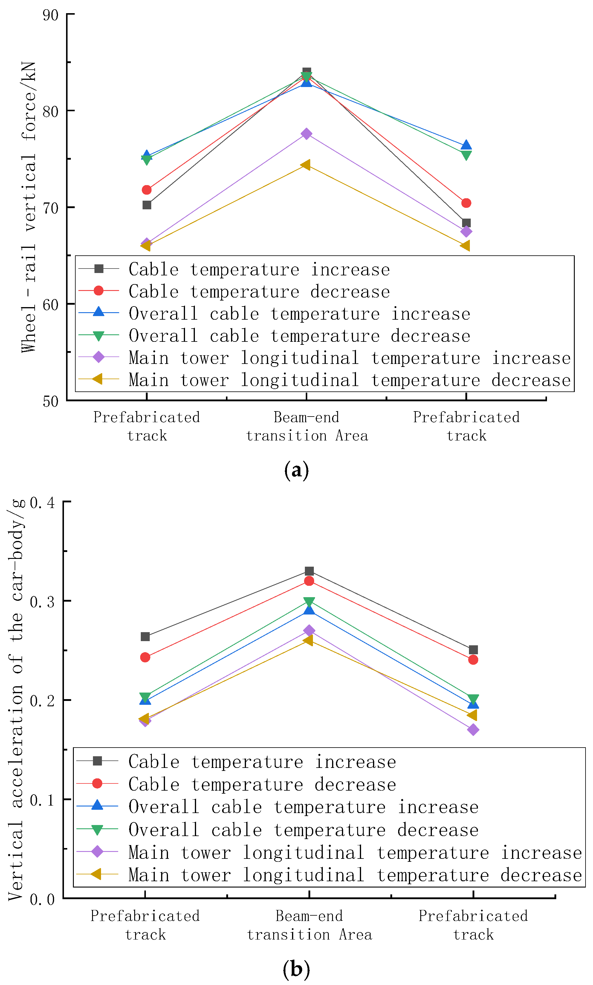
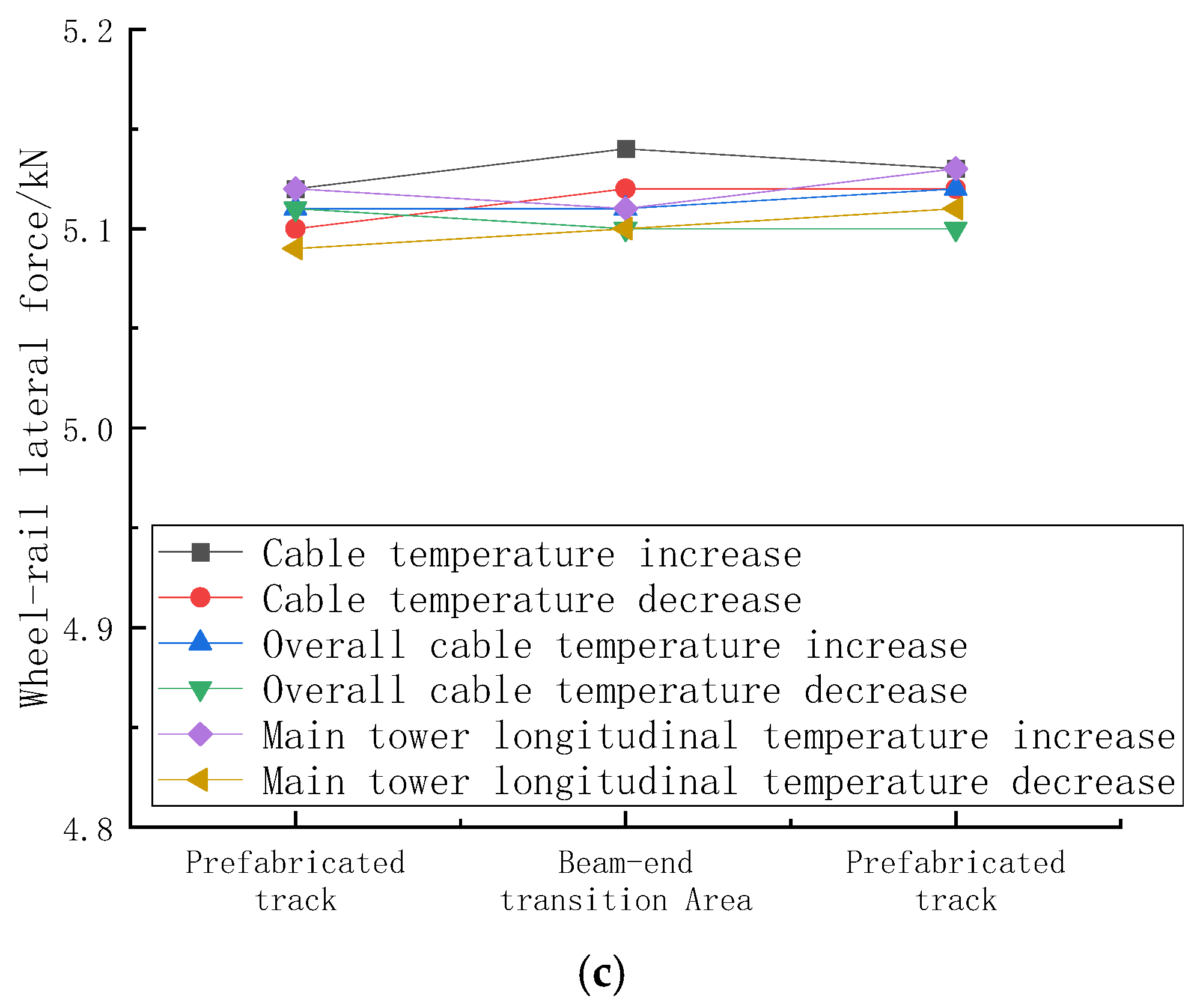
We extracted the beam-end expansion area and the length of a slab from the prefabricated track on each side (front and back), respectively, namely 4.9 m from the prefabricated track, 17.55 m from the beam-end expansion device, and 4.9 m from the prefabricated track transition area, to analyze the performance of the transition area under different temperature load conditions. As revealed through the analysis in Section 2.3, the train’s response in the beam-end area under temperature load conditions was primarily controlled by vertical indicators. Therefore, this section mainly analyzes the wheel-rail vertical force and the train body’s vertical acceleration. The train’s dynamic response in the beam-end expansion area is depicted in Figure 9. When the train ran into the beam-end expansion area from the prefabricated track area, both the wheel-rail vertical force and the train body’s vertical acceleration increased to varying degrees under all temperature load conditions: the maximum variation in the vertical force between the wheel and rail reached up to 20% and that in the vertical acceleration of the train body reached up to 38%, but neither exceeded the specified limits for control indicators. As the train exited the beam-end expansion area, these two indicators both returned to normal levels. The wheel-rail lateral force remained at a similar level throughout the entire transition process. Compared to existing studies on long-span cable-stayed bridges with ballasted tracks [25], prefabricated track systems demonstrate superior operational performance, exhibiting smaller fluctuations in wheel-rail forces within the beam-end expansion area. When contrasted with other ballastless track structures [28], the amplitude of wheel-rail force variations increases with bridge span length. This phenomenon occurs because larger spans amplify thermal deformation effects at bridge expansion joints, subjecting the track structure in the beam-end expansion area to more unfavorable mechanical conditions.

4. Conclusions

(1) For a long-span cable-stayed bridge with prefabricated tracks, the dynamic response of a train body in the beam-end expansion area may peak significantly. However, the train’s dynamic response can still be controlled according to related limits outlined in current standards. At the design stage, it is necessary to pay attention to the vertical stiffness of the beam-end expansion device.
(2) The vertical dynamic response of a train is greatly influenced by the temperature-induced deformation in the beam-end expansion area, while the train’s lateral dynamic response is less affected by it. Among the various conditions, the overall temperature decrease of the bridge results in the largest variation in the train’s dynamic response. As the bridge contracts with temperature decrease, the distance at the beam joints increases, placing the expansion device lacking a substructure in the most unfavorable position for expansion. In contrast, the lateral response remains relatively stable due to the constraints imposed by the expansion device.
(3) The dynamic response indicators of a train in the beam-end expansion area of a long-span urban rail bridge are controlled by the effects of the overall temperature decrease. When the bridge is under a condition of overall temperature increase or decrease, the dynamic stability of the train will transition from excellent to good.
(4) When a train passes through the beam-end expansion area, its dynamic response values show significant changes compared to the prefabricated track structure on the bridge; however, this impact is limited to the range of the expansion transition area. Under different temperature load conditions at the beam ends, the train’s dynamic responses in the transition area remain in a consistent trend.
(5) Based on the above conclusions, it is recommended to install displacement sensors in practical engineering to enable the long-term monitoring of the beam-end expansion zone. During summer and winter, special attention should be paid to the track vertical irregularity trends at corresponding locations to quickly identify and address exceedances of vehicle dynamic stability indicators caused by overall bridge heating or cooling. The structural characteristics of rail expansion devices will generate abrupt peaks in dynamic response, which can serve as a precise reference for mileage positioning at the beam ends of long-span railway bridges during long-term maintenance.

Author Contributions

Supervision, T.X.; methodology, T.X., S.T. and Y.Y.; software, T.X. and Y.Y.; data curation, Y.Y. and C.K.; Formal Analysis, S.T.; writing—original draft preparation, Y.Y.; writing—review and editing, T.X. and C.D.; Conceptualization, S.T. All authors have read and agreed to the published version of the manuscript.

Funding

This research work was financially supported by the National Key R&D Program of China (2022YFB2602900), the 111 Project (B20040), the Research Project of Railway Development (SY12-ZF-23001), the Research and Development Projects of China Railway Siyuan (2021K004) and Research and Development projects of China Railway Shanghai (2021141).

Institutional Review Board Statement

Not applicable.

Informed Consent Statement

Not applicable.

Data Availability Statement

The raw data supporting the conclusions of this article will be made available by the authors on request.

Conflicts of Interest

Author Shuang Tong was employed by the company Ningbo Municipal Railway Investment and Development Co., Ltd. The remaining authors declare that the research was conducted in the absence of any commercial or financial relationships that could be construed as a potential conflict of interest.

References

  1. Chen, H. Research on the static characteristics of ballastless track on urban railway bridge. J. Railw. Eng. Soc. 2023, 40, 31–37. [Google Scholar]
  2. Peng, S. Exploring passenger volume forecast method for suburban railway: A case study of ningbo-xiangshan line. Railw. Constr. Technol. 2022, 6, 117–120. [Google Scholar]
  3. Zhu, B.; Ren, X. Design and mechanical characteristics study of prefabricated track structure for urban railways. China Railw. 2022, 8, 48–54. [Google Scholar]
  4. Chang, L.; Lee, Y. Evaluation of performance of bridge deck expansion joints. J. Perform. Constr. Facil. 2002, 16, 3–9. [Google Scholar] [CrossRef]
  5. Zuada, C.B.; Vervuurt, A.H.J.M.; Peelen, W.H.A.; Leendertz, J.S. Dynamics of modular expansion joints: The Martinus Nijhoff Bridge. Eng. Struct. 2013, 48, 144–154. [Google Scholar] [CrossRef]
  6. McCarthy, E.; Wright, T.; Padgett, J.E.; DesRoches, R.; Bradford, P. Development of an experimentally validated analytical model for modular bridge expansion joint behavior. J. Bridge Eng. 2014, 19, 235–244. [Google Scholar] [CrossRef]
  7. Ding, Y.; Zhang, W.; Au, F.T.K. Effect of dynamic impact at modular bridge expansion joints on bridge design. Eng. Struct. 2016, 127, 645–662. [Google Scholar] [CrossRef]
  8. Li, G.; Han, W.; Zhang, L.; Zhang, Y. Service state evaluation for expansion joints of suspension bridge under extreme vehicle braking load. J. Vib. Shock. 2022, 41, 186–195. [Google Scholar]
  9. Sun, Z.; Zhang, Y. Failure Mechanism of expansion joints in a suspension bridge. J. Bridge Eng. 2016, 21, 05016005. [Google Scholar] [CrossRef]
  10. Deng, L.; Yan, W.; Zhu, Q. Vehicle impact on the deck slab of concrete box-girder bridges due to damaged expansion joints. J. Bridge Eng. 2016, 21, 06015006. [Google Scholar] [CrossRef]
  11. Li, G.; Han, W.; Zhang, L.; Xu, X. Method of wear evaluation on sliding supports in expansion joints based on theories of mechanism motion and wear. China J. Highw. Transp. 2023, 36, 166–178. [Google Scholar]
  12. Guo, H.; Jiang, J.; Gao, M.; Liu, X.; Zhao, H.; Su, P.; Zhu, Y.; He, D. Design and research on the expansion and contraction device at the end of large-span steel bridges on high-speed railways. Railw. Eng. 2020, 60, 1–7. [Google Scholar]
  13. Zhang, X. Research on steel rail expansion adjuster and beam end expansion device of wuhu yangtze river public railway bridge on shanghehang high speed railway. China Railw. 2020, 6, 38–43. [Google Scholar]
  14. Zheng, W.; Zhu, Z.; Sheng, X.; Li, D.; Guo, S. Theoretical and experimental research on deformation adaptability of ballastless tracks on long-span cable-stayed bridge in high-speed railway. J. Railw. Sci. Eng. 2024, 21, 1286–1297. [Google Scholar]
  15. Hou, J.; Wang, J.; Xu, W.; Chen, Y.; Wang, B.; Liu, J.; Shen, B.; Li, Y.; Sun, H. An analysis method of vehicle-bridge coupling vibration considering effects of expansion joint parameters and its application. Struct. Control. Health Monit. 2022, 29, e3065. [Google Scholar] [CrossRef]
  16. Xiao, T.; Hong, Y.; Xu, J.; Pu, Q.; Wen, X. Performance evaluation of cable-stayed bridge expansion joints based on Lasso dimensionality reduction and temperature-displacement-model. Adv. Struct. Eng. 2024, 27, 981–994. [Google Scholar] [CrossRef]
  17. Wang, S.; Tao, T.; Wang, H. Comparison of extraction methods for temperature-induced displacement of expansion joint of long-span cable-stayed bridge. J. Southeast Univ. (Nat. Sci. Ed.) 2023, 53, 664–671. [Google Scholar]
  18. Zhang, Q.; Cai, X.; Xie, K.; Zhang, Y.; Wang, Q.; Wang, T. Multi-objective optimization for switch rail declining values of rail expansion joint on cable-stayed bridge. Struct. Multidiscip. Optim. 2024, 67, 29. [Google Scholar] [CrossRef]
  19. Wang, H.; Shen, R.; Wen, W.; Dai, Q.; Bai, L. Investigation of longitudinal movements of girder ends considering various longitudinal non-linear resistances in railway suspension bridges. J. Constr. Steel Res. 2024, 214, 108446. [Google Scholar] [CrossRef]
  20. Wang, Y.; Gao, M.; Yang, F. Study on the vertical stiffness of bridge expansion joints based on the vehicle-track-bridge coupled model. Shock. Vib. 2022, 2022, 2814807. [Google Scholar] [CrossRef]
  21. Meng, X.; Yao, J.; Liu, P.; Wang, W.; Yang, Y.; Ke, Z. On site testing and analysis of dynamic characteristics of dashengguan yangtze river bridge. China Railw. Sci. 2015, 36, 30–36. [Google Scholar]
  22. Lin, W.; Yoda, T.; Taniguchi, N. Effects of bridge accessories in steel-concrete composite railway bridges in service condition. J. Bridge Eng. 2016, 21, 0401050. [Google Scholar] [CrossRef]
  23. Zhang, S. Analysis of Mechanical Characteristics of CRTS III Slab Ballastless Ttrack Sstructure on Bridge Under Complex Loads. Master’s Thesis, East China Jiaotong University, Nanchang, China, 2020. [Google Scholar]
  24. Tan, X. Study on Mechanical and Deformation Characteristics of CRTSIS III Ballastless Track Under Complicated Temperature. Master’s Thesis, Beijing Jiaotong University, Beijing, China, 2018. [Google Scholar]
  25. Wang, Y.L. Study on the -Track-Bridge Dynamic Response and Track Irregularity at Long Span Bridge Beam End. Ph.D. Thesis, China Academy of Railway Sciences, Beijing, China, 2023. [Google Scholar]
  26. Wang, S. Research on the Influence Analysis and Prediction Method of Rail Corrugation on Subway-Induced Environmental Vibrations. Ph.D. Thesis, Beijing Jiaotong University, Beijing, China, 2024. [Google Scholar]
  27. Yang, Y.; Xin, T.; Li, Q.; Wang, S.; Dai, C.; Kong, C. Application of novel fabricated ballastless track on new designed long-span urban bridges. Adv. Bridge Eng. 2024, 5, 29. [Google Scholar] [CrossRef]
  28. Luo, Y. Research on Static and Dynamic Interaction Between Long-Span Cable-Stayed Bridge and Ballastless Track. Master’s Thesis, Beijing Jiaotong University, Beijing, China, 2023. [Google Scholar]
Figure 1. Finite element model of long-span urban railway cable-stayed bridge.
Applsci 15 11117 g001
Figure 2. Prefabricated structural diagram.
Applsci 15 11117 g002
Figure 3. Finite element model of beam-end expansion area.
Applsci 15 11117 g003
Figure 4. Comparison of vibration modes between self-developed software and MIDAS modal.
Applsci 15 11117 g004
Figure 5. Track longitudinal random irregularity.
Applsci 15 11117 g005
Figure 6. Track alignment random irregularity.
Applsci 15 11117 g006
Figure 7. Deformation curve of cable-stayed bridge.
Applsci 15 11117 g007
Figure 8. Dynamic response of vehicles under no temperature induced beam end deformation as (a) wheel–rail vertical force; (b) wheel–rail lateral force; (c) lateral acceleration of the train body; (d) vertical acceleration of the train body; (e) derailment coefficient; (f) wheel unloading rate.
Applsci 15 11117 g008aApplsci 15 11117 g008b
Figure 9. (a) Dynamic response of vehicles in the beam end transition area for wheel–rail vertical force. (b) Dynamic response of vehicles in the beam-end expansion area for vertical acceleration of the train body. (c) Dynamic response of vehicles in the beam-end expansion area for wheel-rail lateral force.
Applsci 15 11117 g009aApplsci 15 11117 g009b
Table 1. Track structure parameter table.
Track StructureElements TypeMaterialConnection Method
Base slabsolidC60 concretetie
Restrict bosssolidC60 concretetie
Rubber padssolidRubberfrictional
Track slabsolidC50 concretetie
FasteningspringWJ-7elastic
Railbeamrail steelelastic
Table 2. Comparison of modal analysis.
Modal OrderSelf-Developed SoftwareMIDAS ModalError
10.3870.4023.73%
20.4250.4181.67%
30.4400.4214.51%
40.4760.4505.78%
50.5870.5702.98%
60.7880.8072.35%
70.8230.8071.98%
80.9910.9672.48%
91.1021.0990.27%
101.6191.5077.43%
Table 3. Dynamic response of vehicles at the beam end area under different temperature load conditions.
Evaluating IndicatorWithout Temperature LoadCable
Temperature Increase
Cable
Temperature Decrease
Overall
Cable
Temperature Increase
Overall
Cable
Temperature Decrease
Main Tower longitudinal Temperature IncreaseMain Tower Longitudinal Temperature Decrease
Wheel–rail vertical force/kN66.9083.0683.5184.6685.3277.5974.37
Wheel-rail lateral force/kN5.105.145.125.115.105.115.10
Wheel-axle lateral force/kN8.058.098.108.068.058.038.03
Derailment coefficient0.120.100.100.100.090.100.07
Wheel unloading rate0.030.280.280.300.310.190.14
Lateral acceleration of the train body/(m·s−1)0.230.240.230.240.230.220.22
Vertical acceleration of the train body/(m·s−1)0.210.290.310.320.330.270.26
Vertical stability index2.282.312.282.312.282.252.25
Lateral stability index2.222.452.502.522.542.402.37
Disclaimer/Publisher’s Note: The statements, opinions and data contained in all publications are solely those of the individual author(s) and contributor(s) and not of MDPI and/or the editor(s). MDPI and/or the editor(s) disclaim responsibility for any injury to people or property resulting from any ideas, methods, instructions or products referred to in the content.