1. Introduction
Software systems are continually evolving in response to changing business requirements and user expectations. Industry surveys estimate that impact analysis tasks consume 50% to 70% of maintenance resources, making them among the most labor-intensive in software engineering [
1,
2]. Efficient impact analysis relies on robust traceability links that directly connect evolving requirements to specific software artifacts, thereby streamlining modification workflows.
Recent survey studies by Wang et al. [
3] and Wan et al. [
4] classify requirements traceability research over the past decade into three main categories: (1) traditional information retrieval (IR) and statistical similarity methods; (2) machine learning and deep learning (ML/DL) automation techniques; and (3) rule-based, manual, or model-driven engineering (MDE) approaches. Standard evaluation metrics, such as precision, recall, and F1 score, have enabled comparative assessment. However, MDE methods have primarily relied on qualitative evaluation (e.g., case studies, usability testing), lacking systematic quantitative verification in practical scenarios. Wang et al. attribute this to the lack of publicly available benchmark datasets, which are more common for IR and DL methods and facilitate empirical validation. Challenges surrounding ground-truth labeling and experimentation further widen this gap.
Importantly, IR and ML/DL techniques typically operate retrospectively, attempting to recover trace links after artifacts have been created. This process is prone to a recurring anchor problem: omission of one top-level link can disrupt the integrity of all subordinate relationships, introducing reliability risks in real-world maintenance.
To address these limitations, the author advances the CRSensor framework, a proactive traceability management system. CRSensor establishes links in tandem with the generation of analysis model elements, directly anchored to the original requirements. This builds on the author’s prior work, including the CRA Pattern Language for automated model skeleton extraction [
5] and the Trace Metamodel for artifact-level linking [
6], both of which support end-to-end traceability throughout analysis, design, and code generation. CRSensor continuously updates trace links in real time as developers add, modify, or delete model elements, thereby improving both the completeness and accuracy of trace management. The framework enables direct quantitative validation using precision and recall across multiple business applications, fostering fair comparison with IR and ML techniques.
Unlike retrospective tools, CRSensor provides immediate visualizations of change impacts and robust, real-time trace link management, establishing new quantitative evidence for the reliability of model-driven approaches. However, limitations persist due to the scarcity of independently validated reference artifacts and public benchmark datasets. The author’s evaluation encompasses both educational datasets and completed business applications to address these practical constraints.
The structure of this paper is as follows.
Section 2 reviews related work in the field.
Section 3 presents the theoretical background.
Section 4 introduces the lifecycle model for CRSensor.
Section 5 describes the system architecture.
Section 6 shares quantitative evaluation and case studies.
Section 7 discusses benchmarking, extensibility, and limitations.
Section 8 closes with implications and directions for future research.
2. Related Work
Requirements traceability research has seen substantial advancements in theoretical and practical methodologies, as well as in levels of automation, precision, and recall measurements. As summarized in
Appendix B, major prior studies are systematically organized by their main technique/methodology and automation level, clearly illustrating the strengths, limitations, and practical applicability of each approach.
Wang et al. [
3] classified recent studies into three distinct methodologies: information retrieval (IR), machine learning and deep learning (ML/DL), and model-driven engineering (MDE), analyzing the automation levels, evaluation practices, and inherent structural constraints of each category. The IR approach generates automated trace links between requirements and software artifacts using statistical similarity techniques such as VSM and LSI [
4,
7,
8]. Persistent issues have been reported for IR, including ambiguous term matching, limited domain context, and instability in precision and recall [
3]. Though enhancements such as clustering, external feedback, and preprocessing strategies have been proposed for IR [
9], practical business applications remain limited.
ML and DL studies actively leverage deep learning models like BERT, supervised and semi-supervised learning, and transformer-based classifiers [
10,
11,
12]. These techniques achieve high automation but rely on large labeled datasets, complex model structures, and face significant challenges in interpretation and anchor-link reliability [
13]. Wang et al. [
3] and Wan et al. [
4] emphasize the importance of open benchmark datasets for empirical comparison and validation, which remains a primary barrier in MDE research.
MDE adopts explicit trace metamodels to ensure structural consistency, automated traceability management, and regulatory compliance [
14,
15,
16]. Recently, techniques such as TRAM [
16] and problem-frame-based traceability matrices [
17] have emerged to advance further automation and structure. However, most MDE studies emphasize qualitative evaluations such as case analysis and tool usability rather than quantitative performance assessment. Manual trace link maintenance, lack of standardized data and structure, and the difficulty of maintaining consistency across multiple models are repeatedly identified as limitations [
3,
14,
15,
16,
17,
18].
This study identifies gaps in dataset construction, validation using real business artifacts, automated analysis model generation, and the need for embedded empirical evaluation frameworks. There remain structural gaps in the field, including the standardization of data and evaluation procedures, as well as the availability of public datasets for meaningful comparison and broader applicability.
3. Theoretical Background
This section provides a detailed explanation of the theoretical foundations of the CRSensor framework, as proposed in the author’s previous studies [
5,
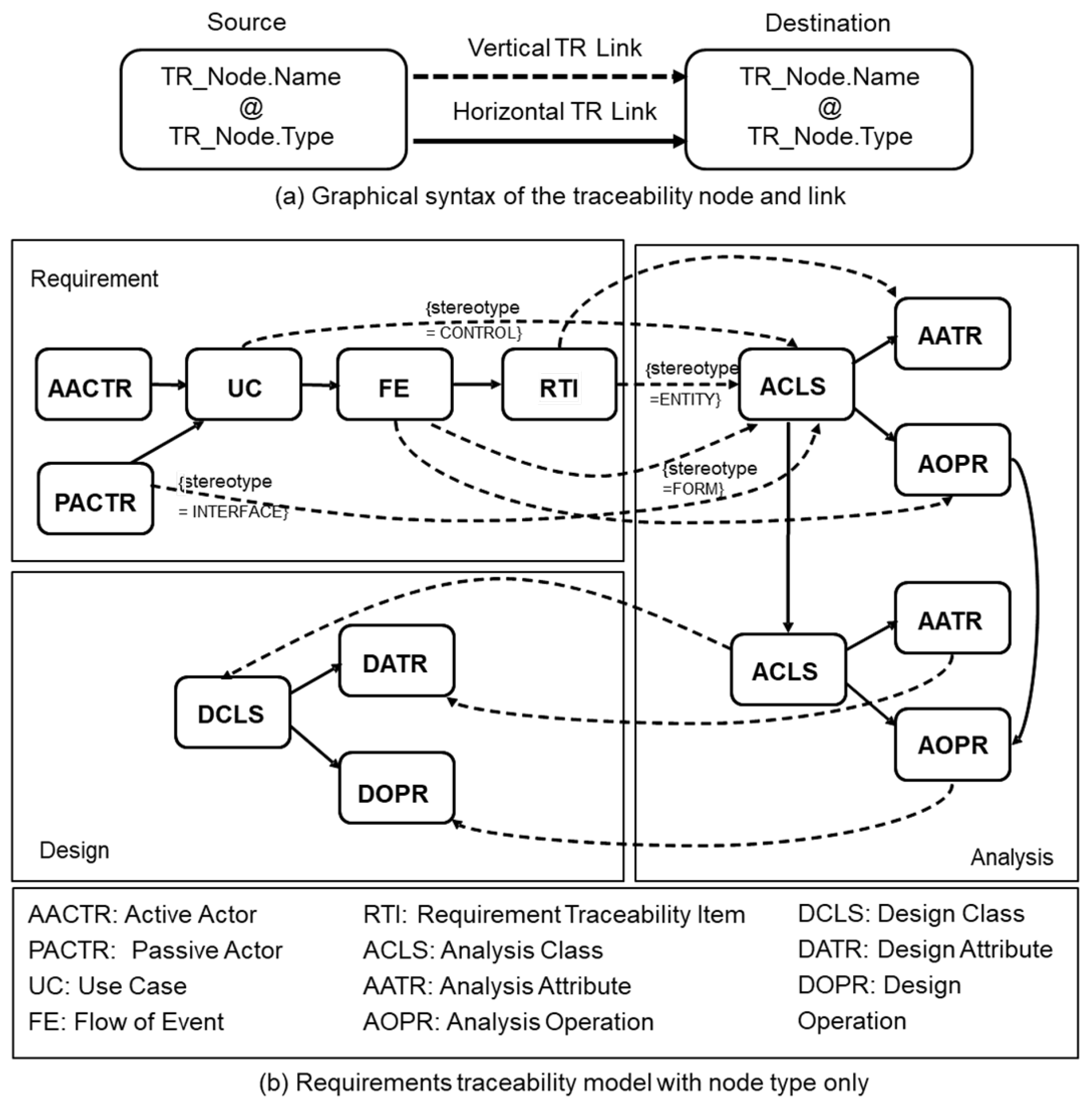
6]. The discussion centers on the structure and operational logic of the CRA Pattern Language and the Trace Metamodel, as illustrated in
Figure 1,
Figure 2 and
Figure 3. The section clarifies how these foundations enable both automated model generation and effective traceability management in practice.
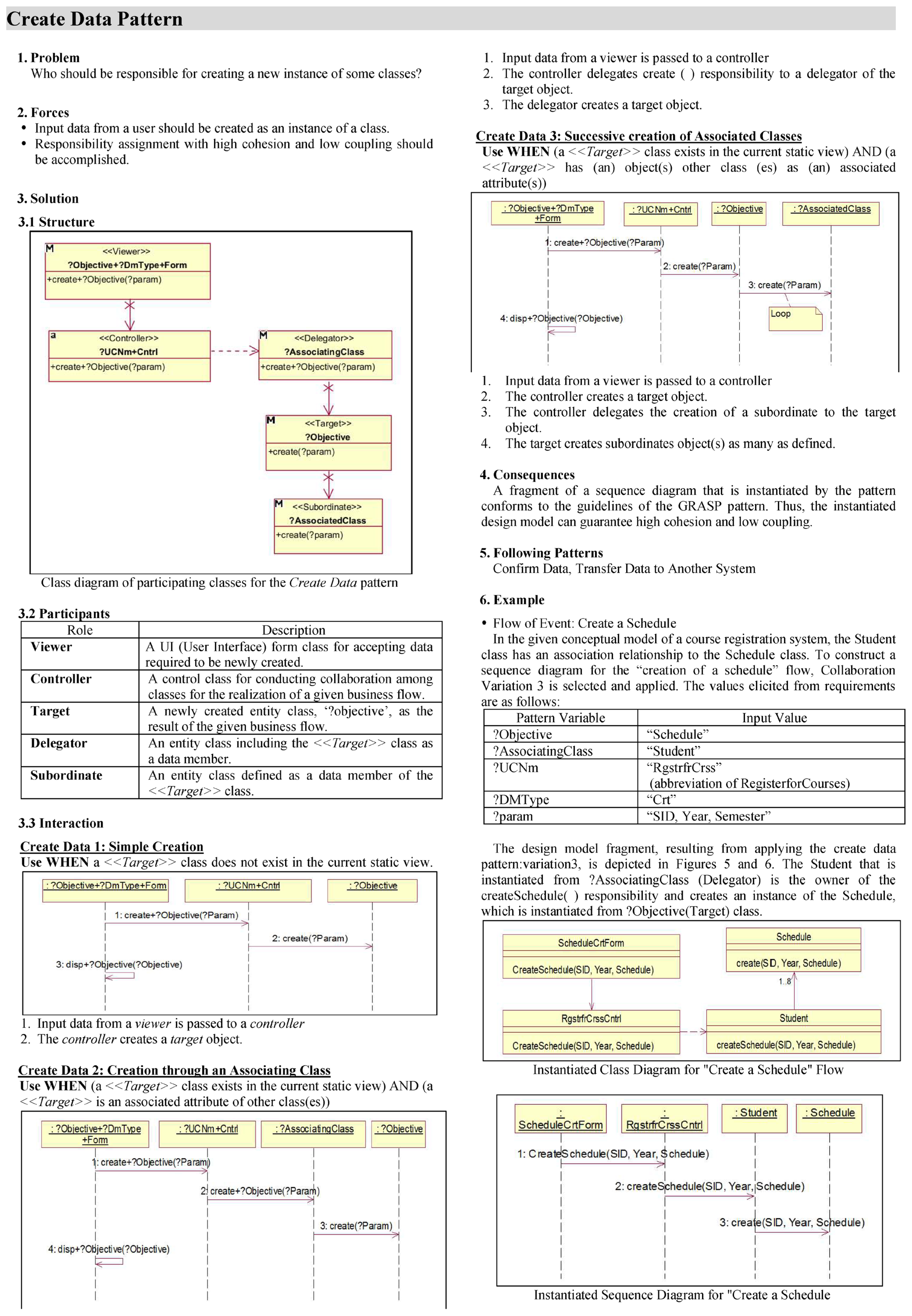
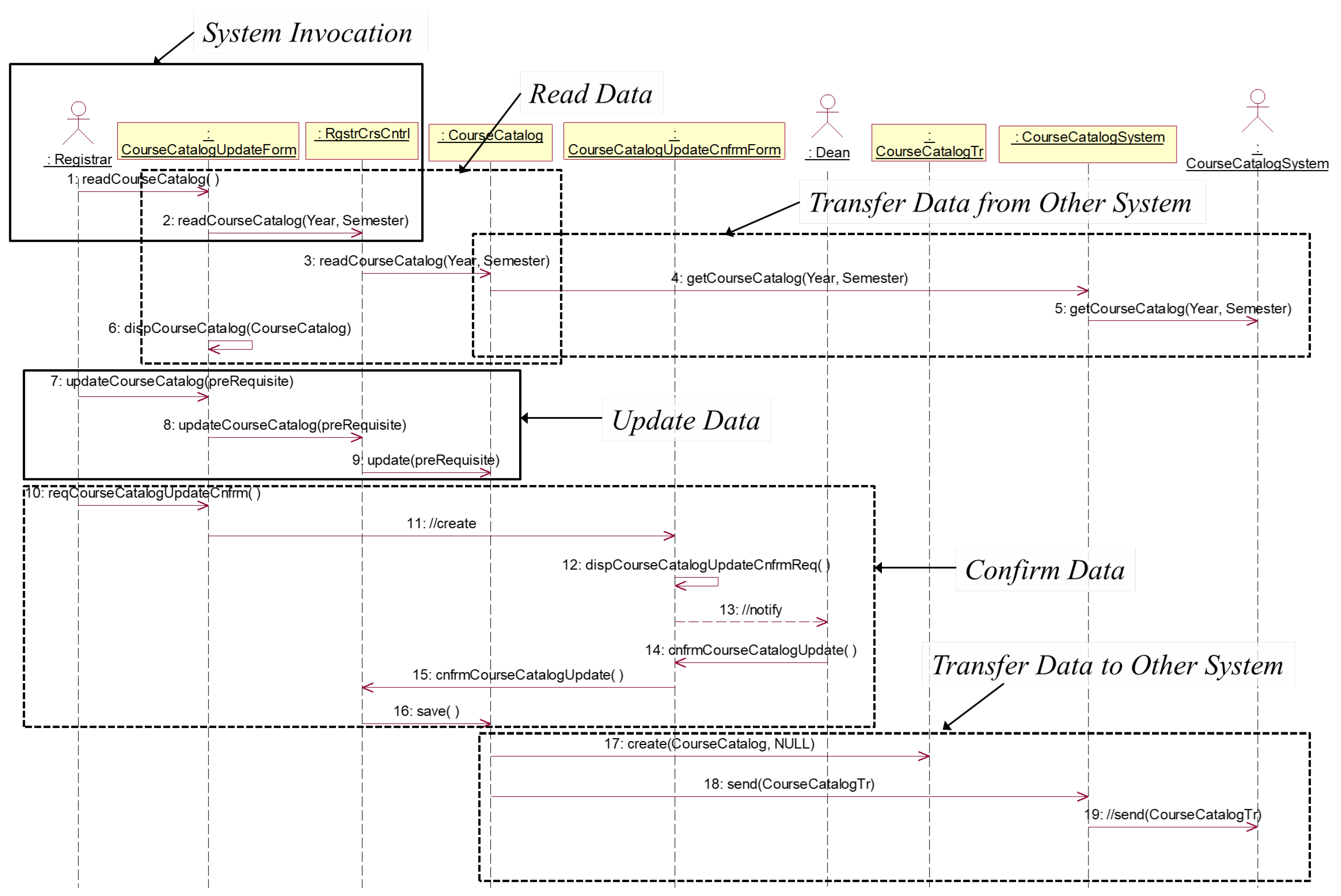
The CRA Pattern Language is defined as a set of 19 patterns derived by decomposing the services of business applications into combinations of CRUD (Create, Read, Update, Delete) operations. These 19 patterns are further categorized into six responsibility pattern categories based on CRUD logic (P1 to P6: Create, Read, Update, Delete, External Send, External Receive). The complete list of these patterns is presented in
Appendix A,
Table A1, and an example of a single pattern definition is shown in
Appendix A,
Figure A2. For each scenario, the analysis model can be constructed by combining a minimum of two and up to six patterns. Essential operations, such as data reading and updating, must always be included, while other actions, like sending or receiving external messages, are included as required by the scenario. This pattern graph provides structured guidance for scenario modeling, helping to define the order of pattern composition, distinguish between mandatory and optional patterns, and support the automated generation of sequence diagrams. This case is illustrated in
Appendix A,
Figure A2, where one pattern is selected from each of the six categories, representing the maximum number of patterns, and these patterns are combined to generate a single sequence.
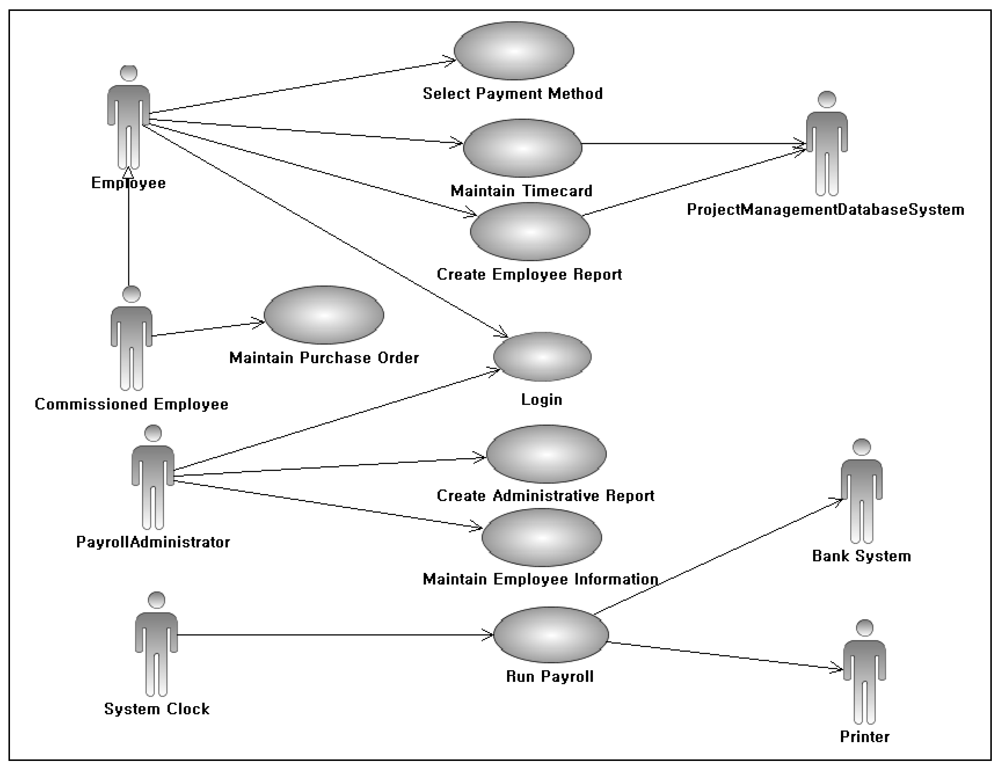
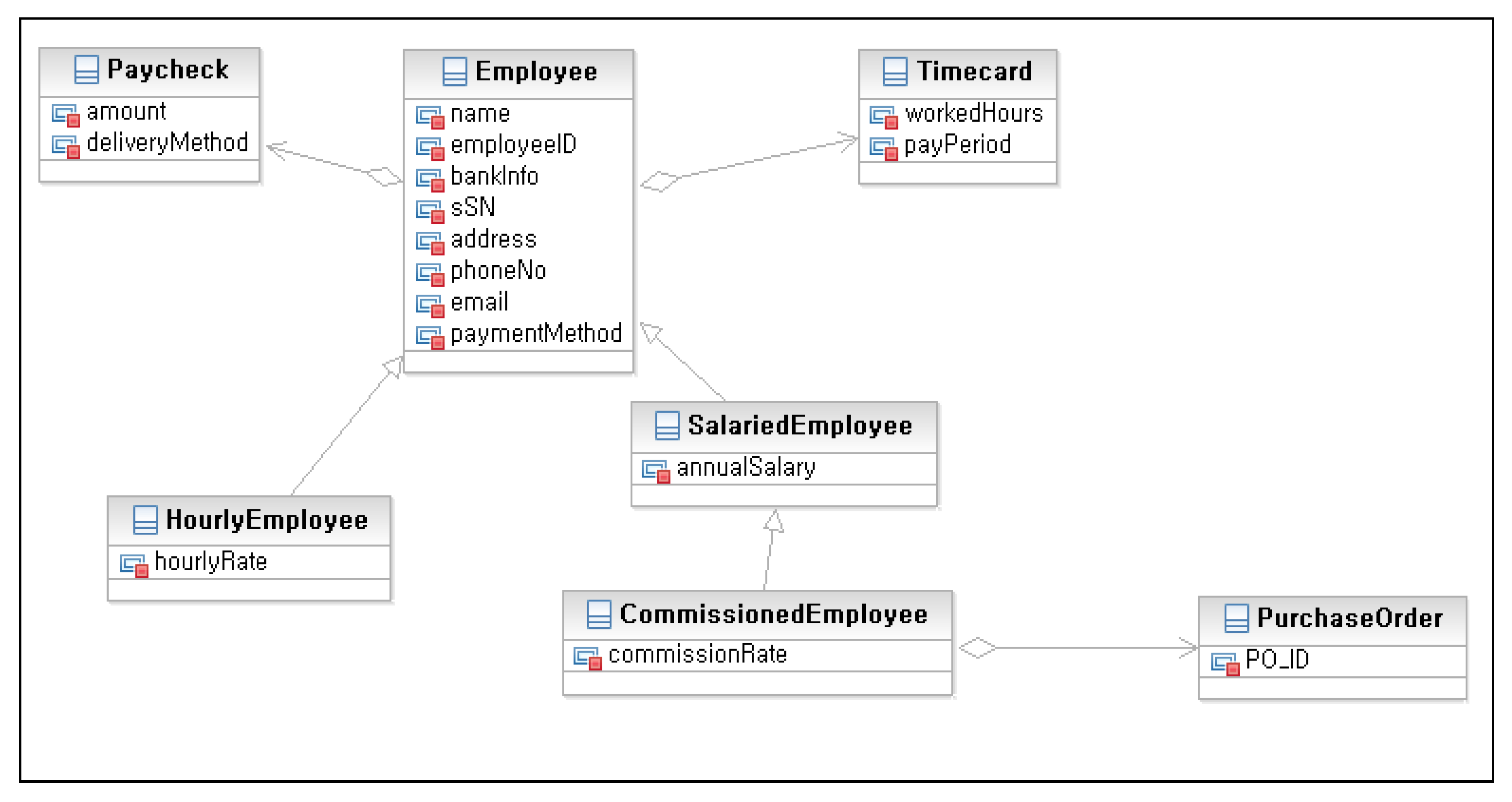
Figure 2 presents the stepwise procedure for constructing the analysis model based on the CRA Pattern Language. The first step involves preparing use case diagrams and an initial class list, and then gathering the required information for completing the CRA pattern metamodel through predefined questions. Based on the answers, the necessary patterns (P1 to P6) and their variables (such as classes, attributes, and interfaces) are determined. In the second step, the selected patterns are connected appropriately to define the structure of the scenario-specific analysis model. Each pattern specifies roles for major classes and responsibilities, and overlapping lifelines serve as connection points between them. In the third step, system mapping is performed to systematically assign answers obtained during analysis and design to pattern variables and to allocate new functions and roles to each class. The scenario may require extending existing classes or creating new classes.
Figure 3 illustrates the hierarchical architecture of the Trace Metamodel employed in this study. This metamodel organizes key stages of the software lifecycle as nodes (artifacts) and links (traceability connections). Requirement nodes include active/passive actors, use cases, flow of events (FE), and requirement traceability items (RTI). Analysis-level nodes include analysis class (ACLS), attribute (AATR), and operation (AOPR). Solid horizontal links connect elements within the same stage, such as FE to RTI or ACLS to AOPR. Dashed vertical links represent traceability between lifecycle stages, for example, from RTI to AOPR or from use case to ACLS.
As the analysis model construction progresses and CRA pattern instances are created, trace links are automatically established among nodes. These links support the preservation of derivation rationale and facilitate reproducibility of the model structure. The Trace Metamodel is continuously updated throughout transitions from analysis to design and implementation, with batch updates performed at key transition points such as model changes or initiation of code generation. This hierarchical traceability structure clearly visualizes system dependencies and change propagation paths, supporting real-time impact analysis and trace management tasks. Empirical case studies and quantitative validation results are presented in
Section 5 and
Section 6.
4. CRSensor Framework
This section provides a comprehensive description of the structure and operational principles of the CRSensor framework, the primary outcome of this research. CRSensor offers real-time traceability and automated artifact synchronization throughout all phases of the development lifecycle, from requirements specification to implementation. The integrated lifecycle process, founded on the CRA Pattern Language and Trace Model, is presented in detail, along with a thorough account of the software architecture and underlying system mechanisms that enable the practical deployment of CRSensor.
4.1. Integrated Lifecycle Model for Requirements Traceability
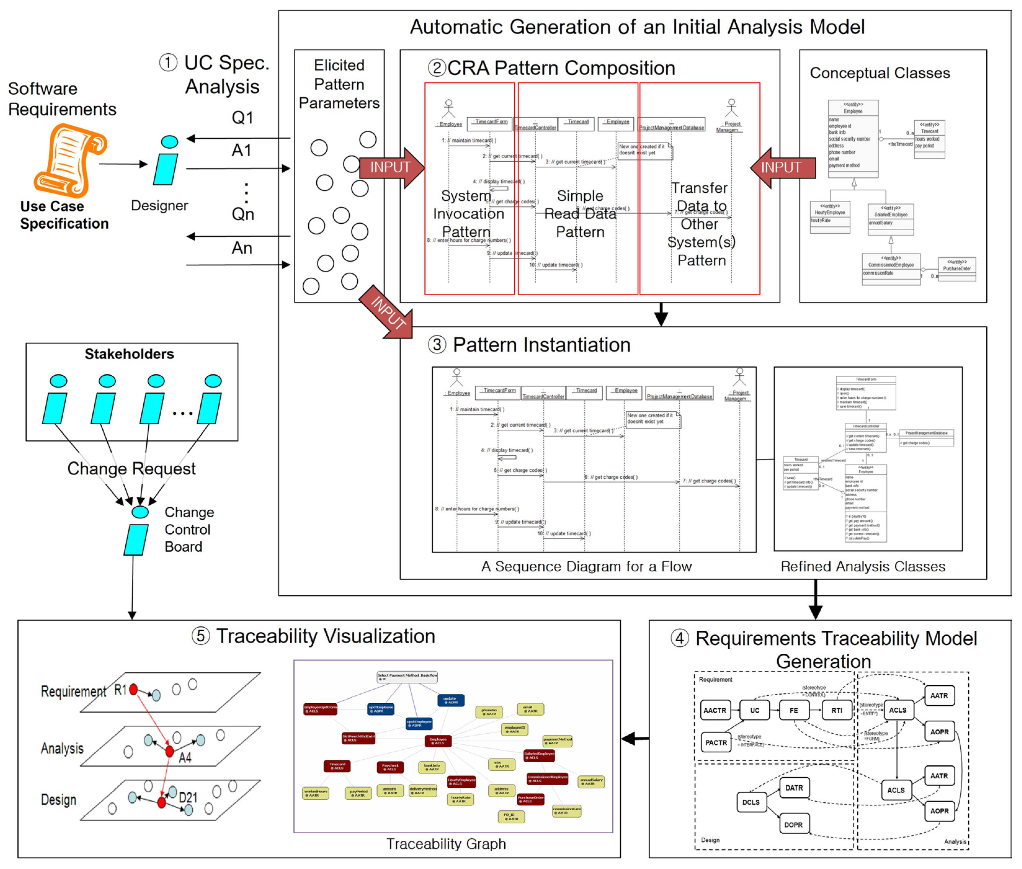
Figure 4 summarizes the integrated operational flow and real-time traceability mechanism of the CRSensor framework, implemented using the CRA Pattern Language and Trace Model. The framework automates change detection, traceability assignment, and impact analysis across the entire software development lifecycle.
UC Specification Analysis: The analyst extracts key parameters from use case specifications by responding to predefined questions.
CRA Pattern Composition: The extracted parameters and conceptual model guide the selection and combination of appropriate CRA patterns, defining the structure of the analysis model.
Pattern Instantiation: The answers from the questions are mapped to CRA pattern instances, enabling automated generation of sequence diagrams, class models, and operations.
Automated Traceability Model Generation: According to the CRA pattern rules, trace links between requirements and analysis artifacts are automatically assigned, establishing a dynamic, real-time network.
Traceability Network Visualization and Impact Analysis: The resulting traceability network is visualized as a tree and graph. Upon change requests, the system immediately provides impact range, propagation paths, and quantitative analysis.
The lifecycle model in
Figure 4 demonstrates that CRSensor is designed to actively address requirement changes, artifact evolution, and collaborative quality management. The architecture supports extensible integration, including deployment in diverse environments and CI/CD pipelines.
Section 7 further discusses practical scenarios for such integration.
4.2. System Architecture of CRSensor
The CRSensor system architecture is implemented as an Eclipse-based plug-in for a CASE tool. Although the current prototype operates in IBM Rational Software Architect 7.0 (RSA) [
19], the core engine and trace model management logic adhere to the UML XMI standard, allowing CRSensor to be adapted to other XMI-compliant Eclipse-based modeling environments, such as Papyrus and MagicDraw.
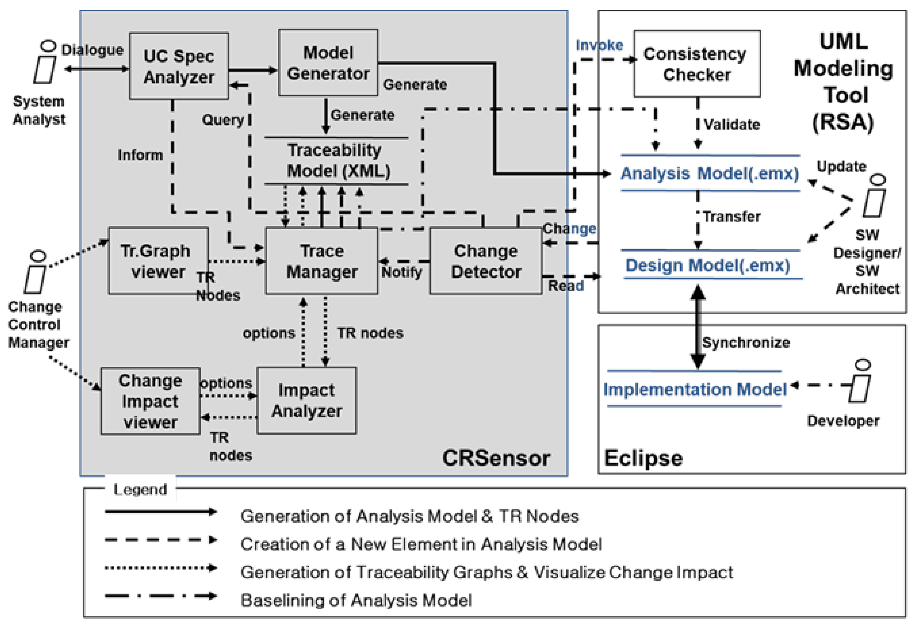
As shown in
Figure 5, all core components consistently utilize the UML XMI format, maximizing both portability and compatibility across various UML modeling tools. The UCSpecAnalyzer module extracts semantically relevant parameters from use case specifications, while the ModelGenerator automatically constructs analysis model structures and sequence diagrams in accordance with the CRA pattern methodology. The ChangeDetector continuously monitors creation, modification, and deletion of artifacts by interfacing with the event systems of both RSA and the operating system, passing these events to the TraceManager. The TraceManager updates trace nodes, links, metadata, and the entire network in real time through all transition phases, from analysis to design and implementation, automatically handling events such as baseline establishment, prefix updates, and the creation of vertical trace links.
For each lifecycle event (artifact creation/modification, stage transition, or diagram extension), the traceability model (in XML format) and the UML model (in emx format) are kept synchronized bidirectionally. A locking mechanism resolves concurrent editing and ensures data consistency. According to the event flows identified in the legend of
Figure 5, the ChangeDetector transmits artifact creation/modification events to the TraceManager in real-time, keeping the network updated. The TraceManager also performs periodic batch updates for trace model metadata, and the UML and traceability models are kept mutually synchronized through ongoing exchanges.
Impact analysis, including propagation monitoring and quantitative evaluation, is handled in real-time by the ImpactAnalyzer and ChangeImpactViewer modules, with immediate visualization through the TrGraphViewer, ImpactAnalyzer, and ChangeImpactViewer interfaces.
4.3. UML Modeling Tool Integration and Instrumentation
RSA was selected as the implementation platform for prototyping and experiments. However, the event detection policy and trace model synchronization logic in CRSensor are designed independently of any specific modeling tool, enabling broad applicability.
Commercial modeling tools, such as RSA, often restrict direct access to the source code, posing technical challenges for detecting real-time model changes. To address this, CRSensor incorporates an instrumentation strategy inspired by Egyed [
20]. This approach allows the system to capture a full range of relevant signals, including keyboard and mouse input, operating system events, and internal model change notifications. In this study, a hooking technique was adopted that enables immediate event detection and data synchronization without modifying the internal mechanisms of RSA itself.
The interaction sequence presented in
Figure 6 provides a detailed description of each architectural function. When RSA is launched, the TraceManager responds by activating the instrumentation interface (step 1) and locating the RSA modeling environment to initiate UML model change management (step 2). As the user performs creation, modification, or deletion in the UML model, the instrumentation layer responds in real time, capturing all such events (step 3). The ChangeDetector classifies and extracts event data via hooking (step 4) and, upon detecting a valid model change, updates intermediate structures and passes the information to the TraceManager for traceability management (step 5). During synchronization, CRSensor temporarily locks the RSA model (step 6) to ensure strict data consistency and transactional integrity between models during updates.
The core logic for event detection and data synchronization, including hooking, event parsing, and trace model updates, represents a key technical contribution of this research. The mapping procedures, operational steps, and concurrency control are illustrated comprehensively in the data/event workflow in
Figure 5.
This instrumentation algorithm is not limited to RSA. By adapting the event interface to other XMI-compliant modeling tools, the architecture and impact analysis features of CRSensor can be broadly reused. As a result, CRSensor enables fully automated, real-time editing, detection, traceability, synchronization, and impact analysis across diverse commercial UML environments, without requiring modification to the constituent tools’ internal structures.
5. Case Study
This section presents an extended case study based on the Payroll Management System, which the author previously investigated through the manual application of the CRA pattern language. While earlier research primarily focused on generating analysis models, the present work employs the CRSensor tool to illustrate how requirements, analysis models, traceability models, and impact analysis are seamlessly integrated within an automated pipeline. The study also evaluates how real-time traceability enhances engineering effectiveness.
Since the input data and output artifacts for the CRSensor-driven case are largely diagrammatic, including all detailed diagrams in the main text might undermine readability. Therefore, the current section concentrates on explaining core analysis steps and the implementation mechanisms using concrete operational examples, while detailed input and output diagrams are provided separately in
Appendix C. This approach ensures that the narrative centers on the internal mechanisms, using practical cases, without sacrificing the structure or comprehension of the analysis process and its outcomes.
The case specifically assesses how a requirements change, consolidating three payroll delivery methods (direct receipt, mail, and bank transfer) into a single bank transfer mechanism, affects the entire software system. The CRSensor automation tool is used to quantitatively analyze the propagation and scope of impact of this change across the modeled business workflow.
5.1. Automatic Generation of Analysis Model
Based on the architecture and principles for real-time synchronization between requirements and analysis models set out in the previous sections, the CRSensor tool is applied to simulate practical automation in the Payroll Management System.
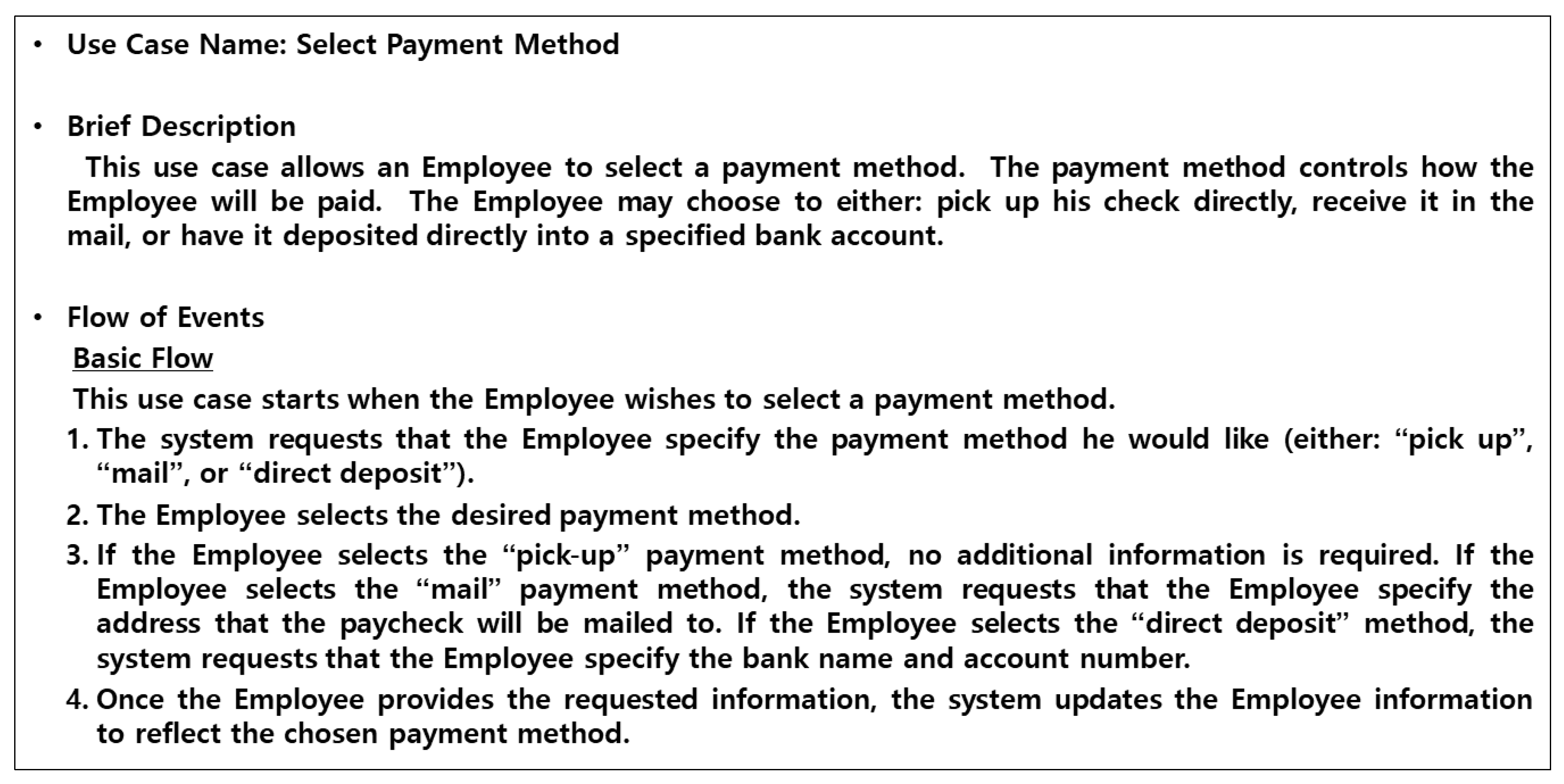
Figure 7 captures a step in which the analyst uploads requirements artifacts and provides essential information for automatic generation of the analysis model.
Within the ConfigureUMLModel tab in CRSensor, an analyst uploads model files containing the structure of use cases and classes, such as RSA-formatted .emx files. This action establishes the foundation for automated analysis. In the UCAnalyzer tab, the analyst retrieves the use case specification in Word format via UCBrowser, making requirement data directly available for reference during analysis. UCAnalyzer supplies a predefined set of questions, and the analyst selects answers by referencing the uploaded artifacts and diagrams.
As shown in
Figure 7, CRSensor extracts actual attribute values from requirement artifacts and displays them in dropdown lists for each question. This restricts selections to valid values alone, fundamentally preventing the generation of analysis model elements that lack traceability to requirements artifacts due to arbitrary input. The process directly contributes to higher quality analysis models and prevents the occurrence of orphan nodes in the trace model.
In the example workflow of
Figure 7, when an answer is selected for a question about the basic flow of the
Select Payment Method use case, the selected term is automatically tagged with an FE-type trace node and identifier on the UCBrowser specification screen. In practice, analysts would navigate across multiple tabs, but the figure is composed to present input and trace tagging in a single view.
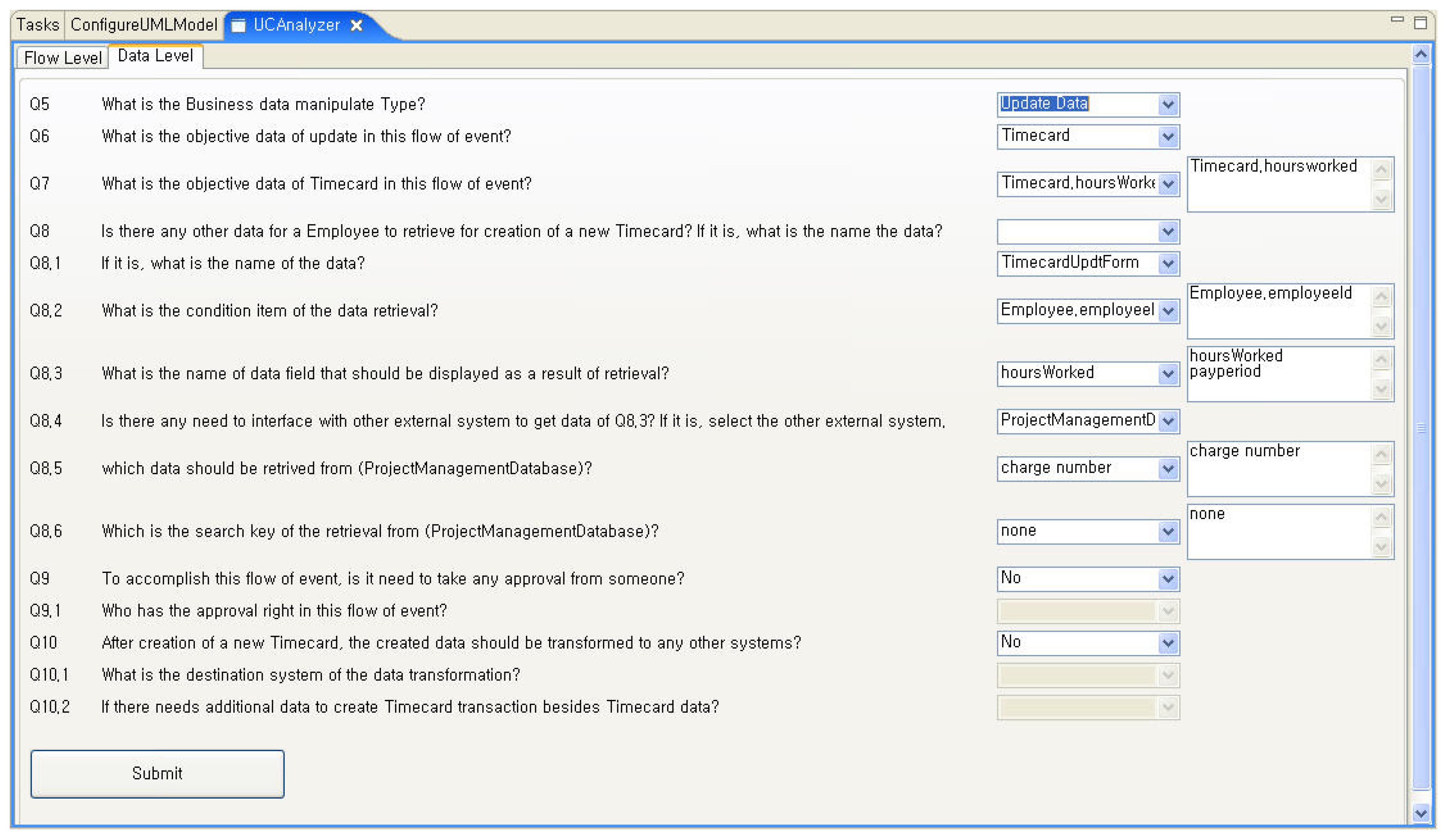
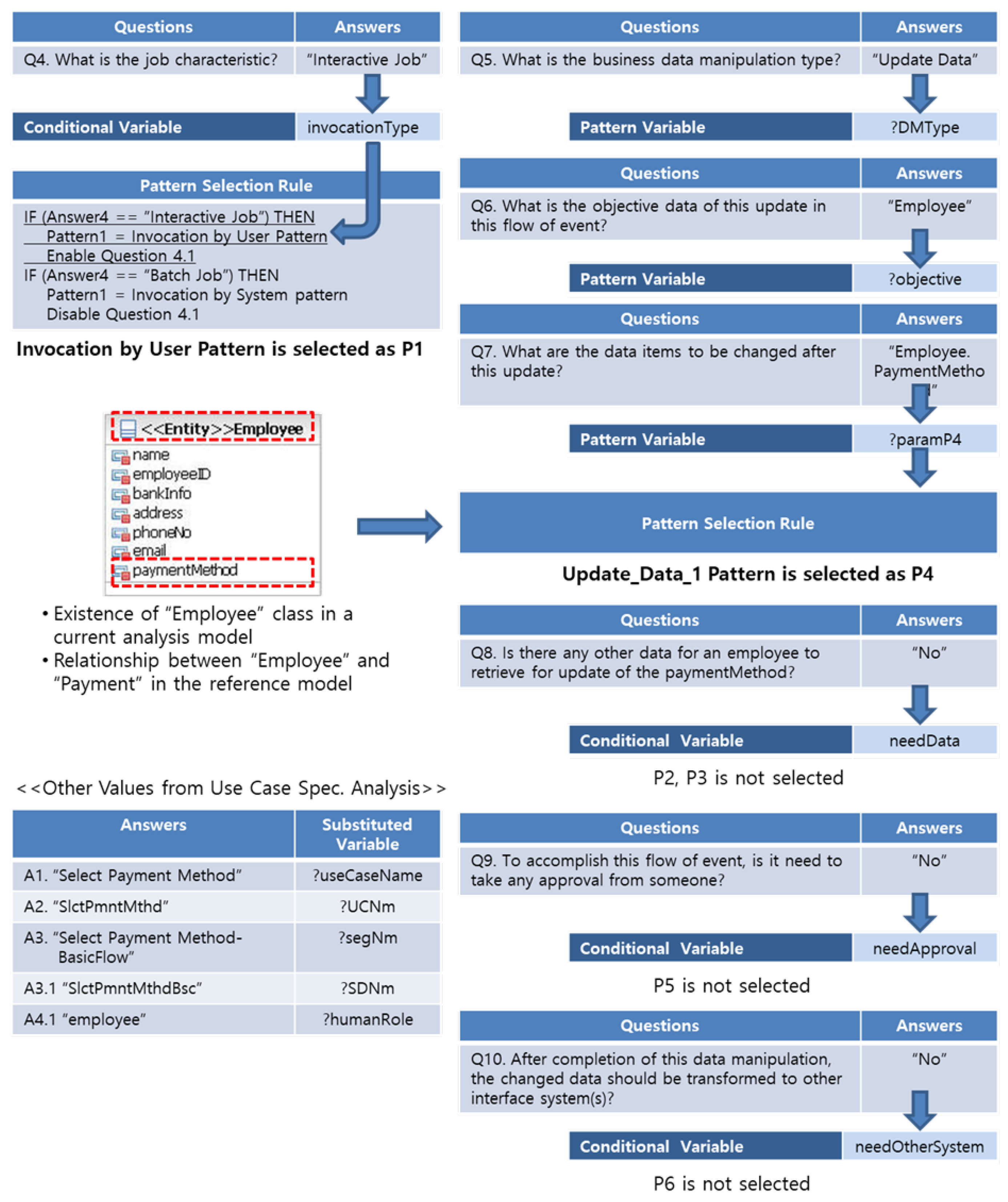
Figure 8 illustrates how the system analyst’s answers to key questions related to the basic flow of
Select Payment Method are processed by the CRA pattern combination rules, resulting in automated pattern mapping and parameter assignment. The questions displayed in the UCAnalyzer GUI in
Figure 7 are part of a set designed to interpret requirements specifications for CRA pattern application, and the remaining questions, along with their answers, can be found in
Figure 8.
Reviewing the impact of each answer on pattern selection. For instance, when Interactive Job is chosen for Q4 (Job characteristic), the “Invocation by User” pattern (P1) is automatically selected. Similarly, if Update Data is mapped for business data manipulation type (Q5), Employee (P6), and associated attributes (P7) are set as parameters. Each question and answer is systematically linked with the conditional variables, pattern variables, selection rules, and parameter mapping in the CRA pattern language.
Questions such as “Is additional data lookup required?”, “Is approval required?” and “Is interface with other systems needed?” are constructed to align with the decision flow of the CRA pattern language. When the analyst answers “No” to each, the corresponding CRA pattern (P2, P3, P5, P6) is automatically excluded. At the bottom, the extraction and mapping of each answer to CRA pattern variables (e.g., “?useCaseName”, “?objective”) is summarized. The definition of variables for each pattern can be found in the specifications for the Create Data pattern, as shown in the sample in
Appendix A.
Thus,
Figure 8 provides a comprehensive visualization of the branching logic and automated pattern selection, parameter and meta-information extraction, and the real-time mapping process between the GUI responses and the CRA pattern language specification.
5.2. Automated Trace Model Generation Between Requirements and Analysis
When CRSensor generates analysis model elements, the TraceManager extracts the linkage information between those elements and the associated requirements artifacts in real time, recording it in an XML-based trace model.
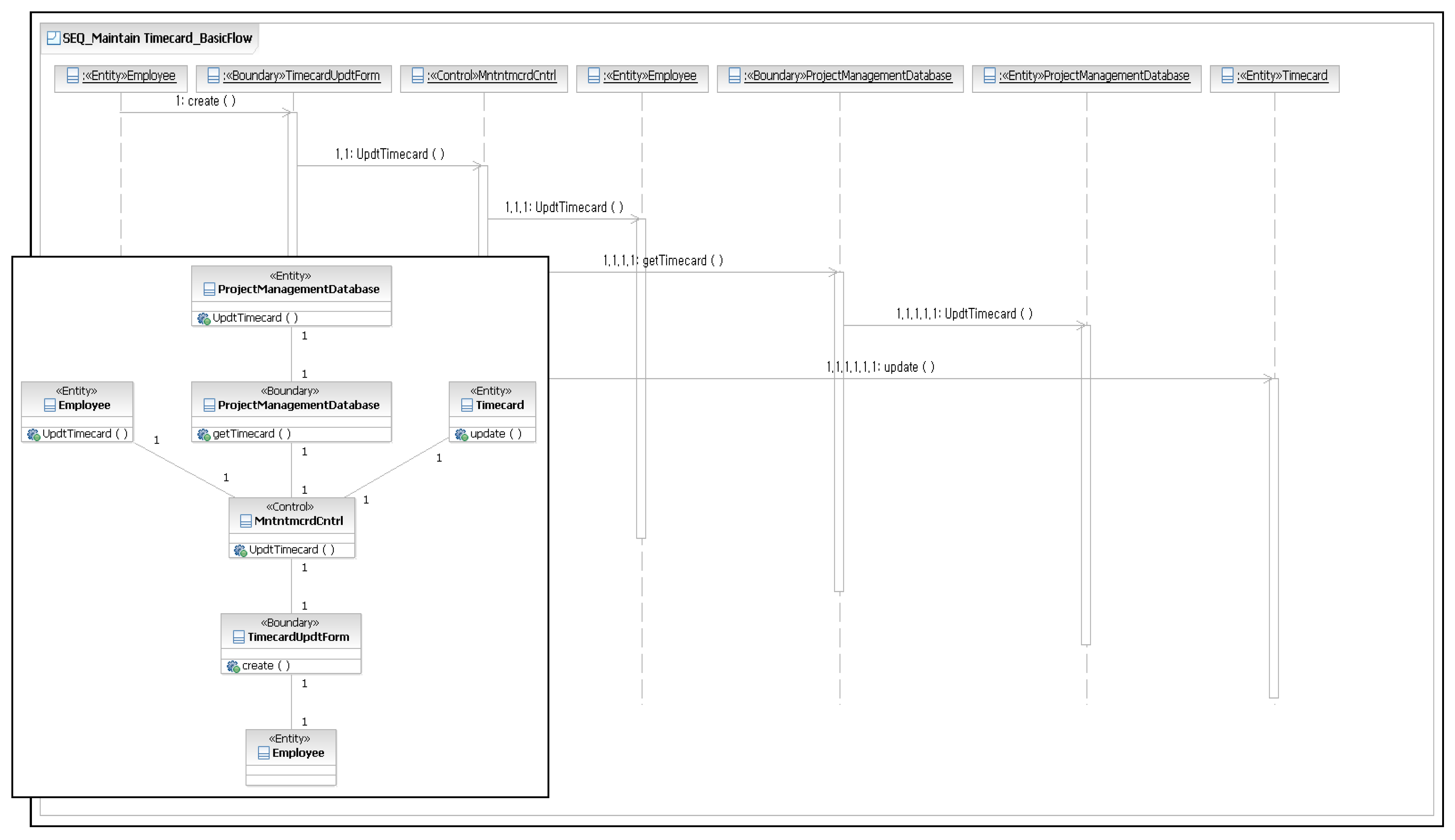
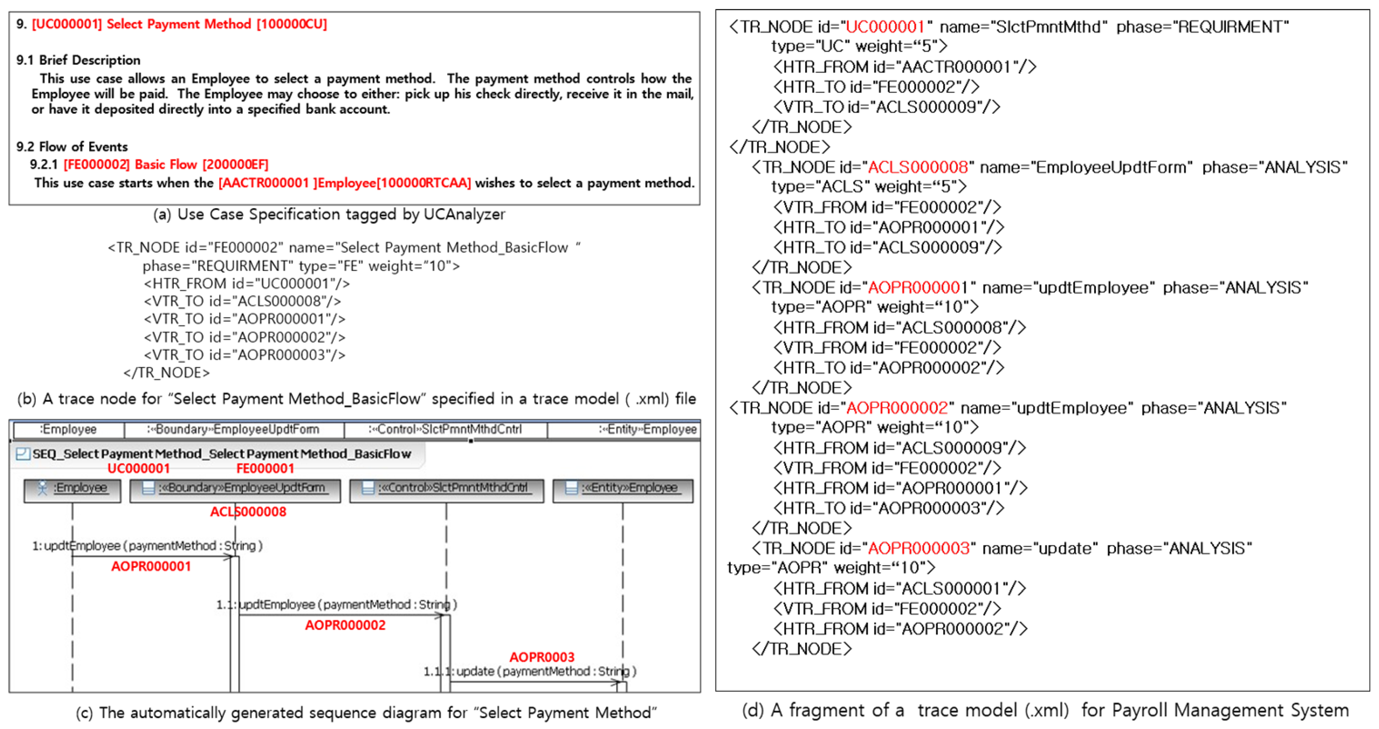
Figure 9 presents the internal process step by step, explaining the trace node structure, inter-element connections, and linking methods.
Panel (a) shows that selecting the basic flow for Select Payment Method in UCAnalyzer generates an FE node and logically connects it to the major analysis artifacts. Panel (b) depicts each trace node defined in XML with metadata such as id, name, phase, and type, as well as HTR_FROM and VTR_TO fields linking to upstream and downstream nodes. The weight value is used as a quantitative metric for impact analysis and maintainability.
Panel (c) illustrates how the FE node serves as the foundation for an automatically constructed sequence diagram, and Panel (d) details the explicit links among requirements and analysis artifacts using HTR and VTR attributes in the XML trace model. In practical applications, the trace model will encompass a much larger set of artifacts and requirements than the partial example in
Figure 9.
Any manual modifications or extensions made by analysts are monitored by CRSensor, which updates the trace model immediately upon each event detected in RSA. This ensures continuous synchronization between requirements and analysis artifacts at event granularity, sustaining high standards of consistency and reliability in traceability.
The method for creating automatic trace models and synchronizing them in real-time is fully consistent with the CRSensor architecture described earlier, incorporating event-level data parsing, node management, and dynamic UML-XML mapping mechanisms. Trace relationships between requirements and analysis artifacts are automatically updated throughout the modeling process, maintaining system robustness and reliability.
5.3. Instrumentation-Based Model Refinement and Traceability Integration
Although
Section 5.2 reviewed the simultaneous automation of analysis and trace models by CRSensor, real-world business analysis projects often require repeated refinement and expansion following initial automation. As analysts introduce new classes, attributes, relationships, or domain-specific changes within UML tools such as RSA, the event detection policies of CRSensor ensure that all changes remain integrated within the traceability structure. System-level monitoring, without access to source code, captures every manual change as it occurs, recording them in the trace model in real-time.
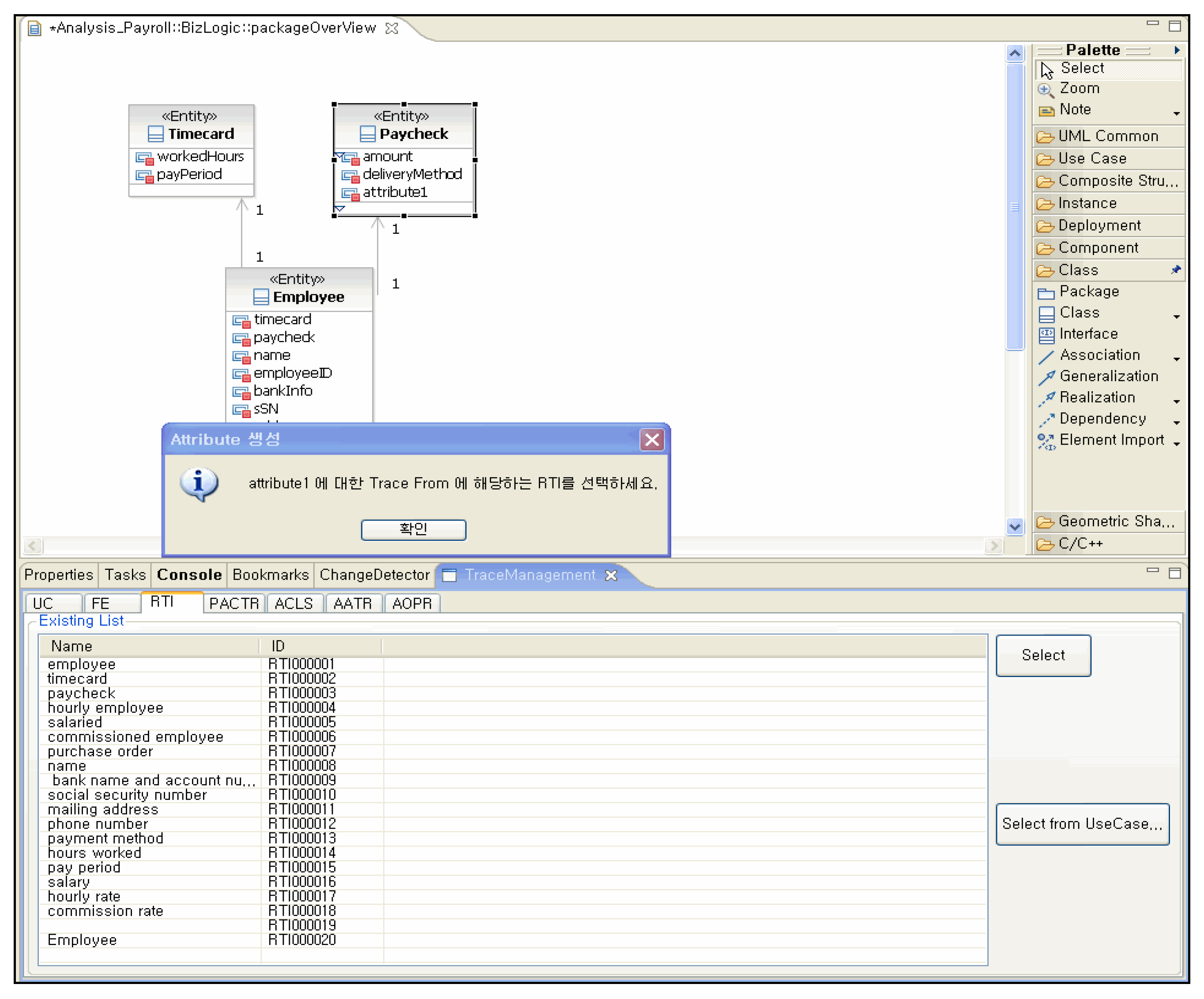
Figure 10 illustrates the dialog interface that appears when an analyst attempts to save a refined model in RSA. The tool automatically prompts for the requirement artifact or traceable item that justifies the modification or addition, reinforcing traceability and maintaining systematic model quality throughout refinement.
While the requirement for traceability justification may occasionally be a burden for practitioners, the automated generation and requirement-based linking process means that the majority of model nodes are already automatically traced. Consequently, only a limited number of manual entries are needed, striking an appropriate balance between automation and manual supplementation.
Automation coverage and trace link generation rates are quantitatively assessed in
Section 6.
5.4. Transition and Consistency Between Analysis and Design Models
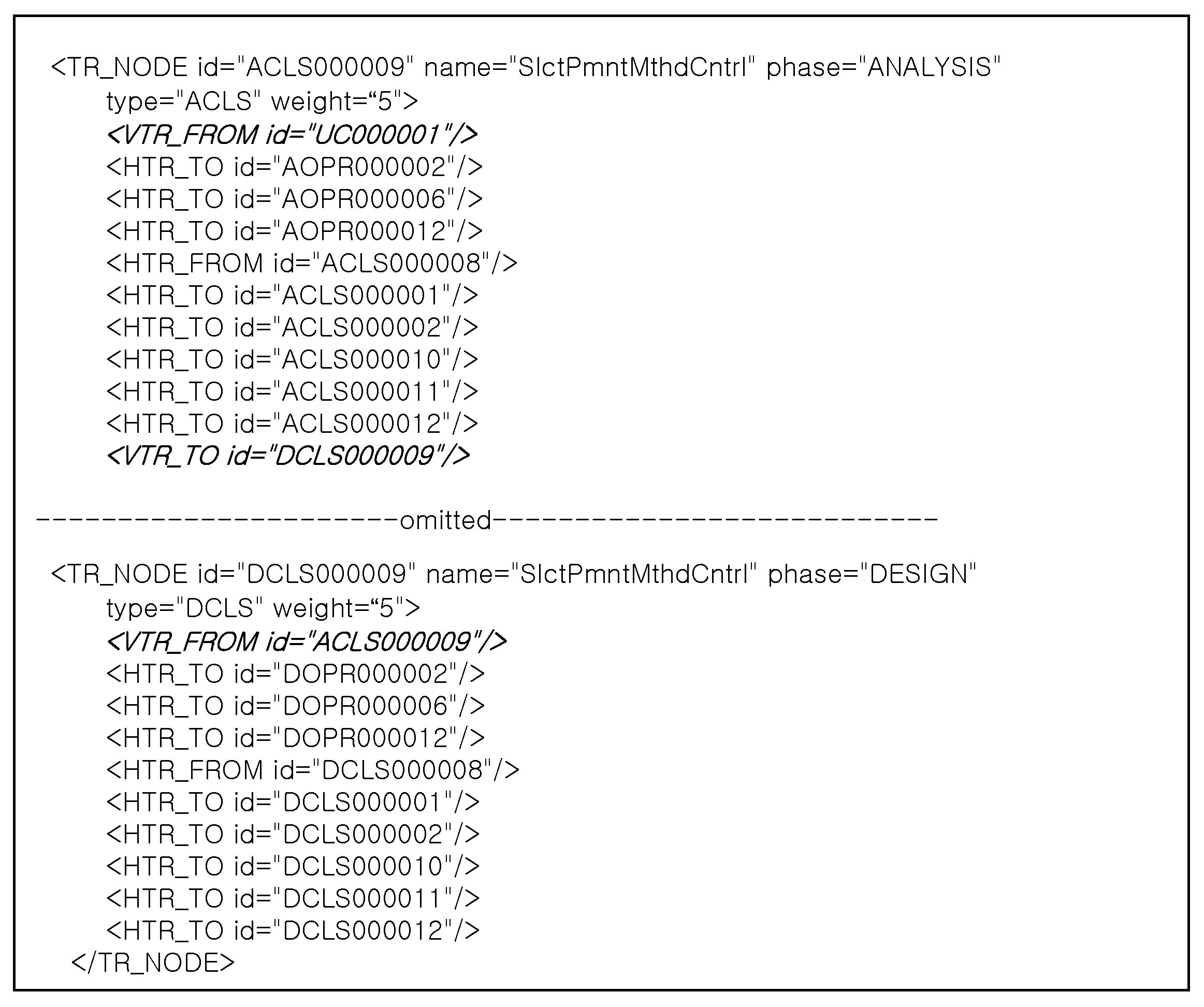
The preceding section examined the mechanisms for model refinement and real-time trace management during the analysis and design phases. Once the analysis model is fixed at Version 1.0, CRSensor migrates all trace nodes with an ‘A’ prefix from the analysis phase to the design phase as ‘D’-prefixed nodes, as shown in
Figure 11. Each analysis model element is mapped one-to-one to a design model element with the same name, and all trace links (HTR_FROM/TO, VTR_FROM/TO) are synchronized with the design-phase identifiers.
During the design phase, changes and refinements made in RSA are detected and captured by CRSensor, ensuring that every modified element remains mapped to the correct analysis artifact or requirement. This process achieves seamless transition of analysis models and migration of the trace model to the design phase, maintaining consistency and integrity in traceability as the model evolves.
5.5. Traceability Graph Visualization and Change Impact Analysis
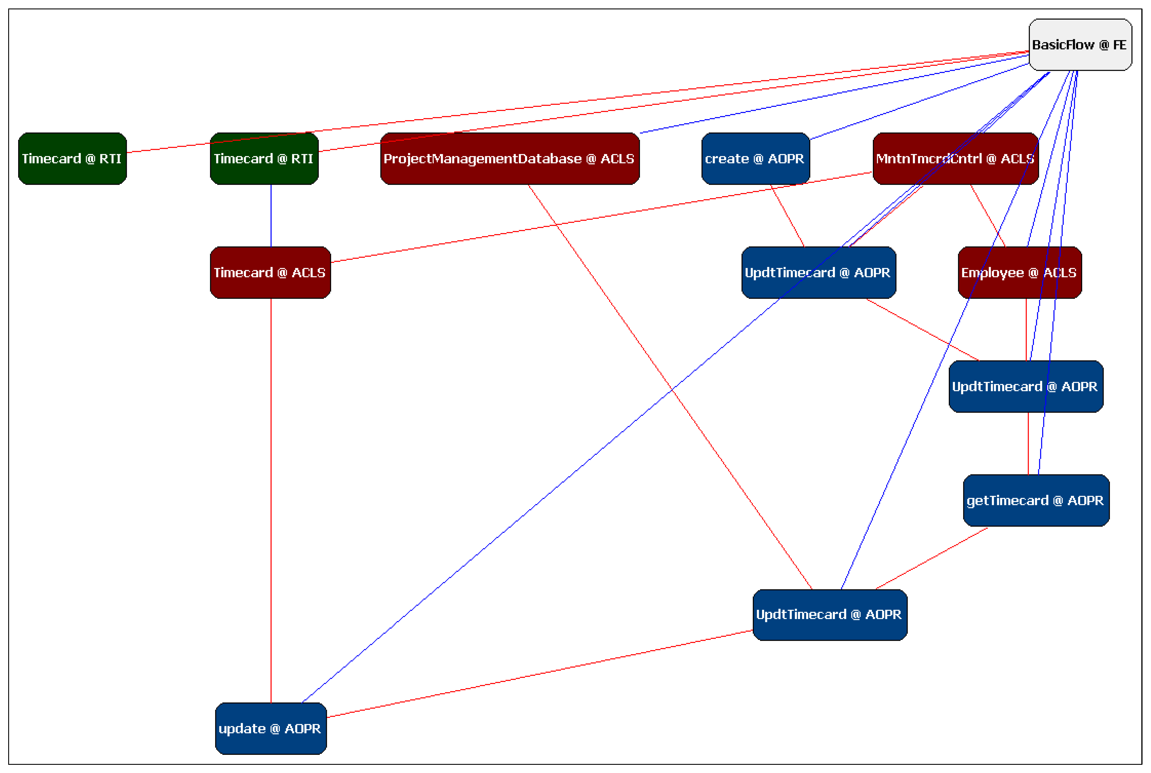
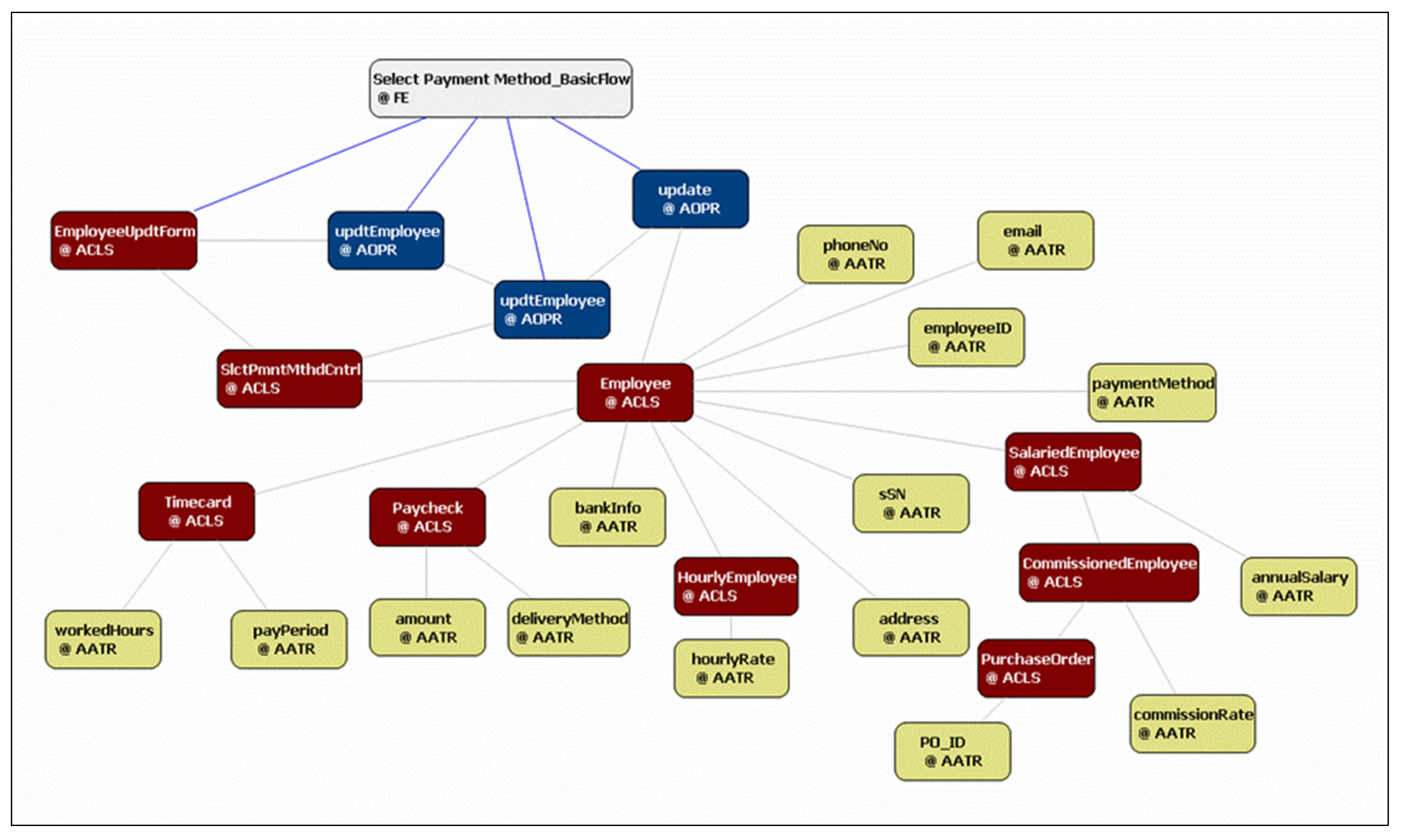
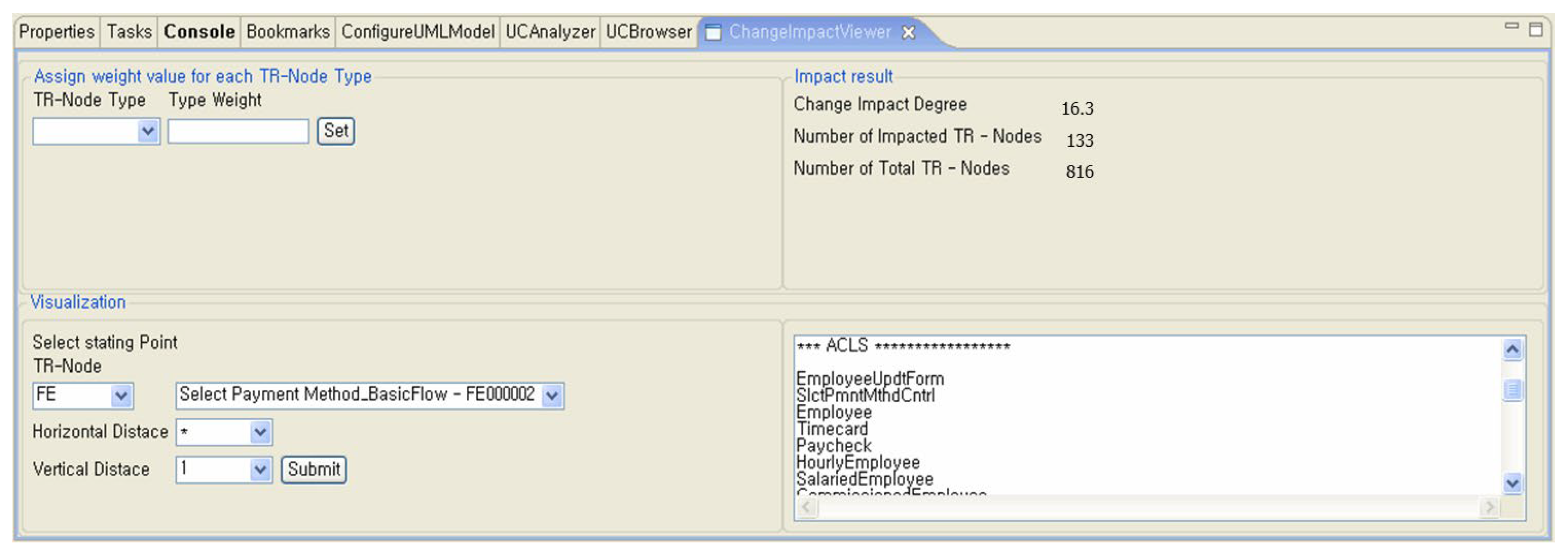
Following model creation, refinement, and transition, CRSensor’s ChangeImpactViewer visually maps and quantitatively analyzes the propagation of changes throughout the trace model. By specifying any trace node, such as FE000002 (
Select Payment Method-BasicFlow), and adjusting trace distance parameters, CRSensor displays the related trace network in both graphical form and structured lists, as seen in
Figure 12 and
Figure 13.
In
Figure 12, when trace distance is set to one, only directly connected links are highlighted in bold (vertical links are VTR_TO, horizontal links are HTR_TO), illustrating the event-driven traversal and graph filtering architecture in CRSensor.
Figure 13 demonstrates that setting the horizontal distance to all and the vertical distance to one yields a list of 133 impacted nodes out of a total of 816, resulting in a Change Impact Degree (CID) of 16.3%. The tool also provides a simultaneous list of affected nodes, allowing change controllers and project managers to track propagation paths and the scope of impact immediately. This example aligns directly with the event-driven management, propagation algorithms, and dynamic visualization structures previously established.
In
Section 5, the internal mechanism of CRSensor was explained using the realization of the basic flow of
Select Payment Method, which generates a small number of analysis model elements to illustrate the internally produced data diagrammatically. Additional examples of CRSensor input and output values for basic flows involving a larger number of analysis elements are provided in
Appendix C.2.
6. Quantitative Evaluation and Results
This section provides a quantitative evaluation of the CRSensor framework, assessing both automation accuracy and practical applicability across a diverse set of business applications, including both educational examples and actual project cases.
Section 6.1 introduces the rationale for selecting the validation targets and clarifies the scope of performance metrics, specifically precision and recall, which are evaluated using educational cases. At the same time, PCD is measured for both industrial and educational datasets. The section also discusses the limitations inherent in trace link validation.
Section 6.2 outlines the quantitative evaluation metrics and formulas (precision, recall, and PCD) used in the study.
Section 6.3 presents the experimental results in detail, highlighting the contributions of the quantitative approach, the limitations due to non-public datasets, and indicating that further analysis continues in
Section 7.
6.1. Verification Targets
To comprehensively evaluate the effectiveness, accuracy, and generalizability of the CRSensor framework, automation techniques were applied to four distinct business applications. The previous chapter focused on a single payroll management system; here, we broaden the experimental spectrum in two directions.
First, precise verification of both accuracy and scope was achieved by employing two well-structured educational cases, the Payroll Management System and the Course Registration System, based on standard software engineering textbooks and lab materials. These datasets enable a systematic comparison against reference answers and a detailed evaluation of the quality of trace links and analysis models.
Second, to examine the robustness and practical suitability of pattern-based automation in real business environments, two completed small-scale project cases (e-bidding system and order processing system) were included. These cases encompass domain-specific noise, ambiguity, and incompleteness, enabling an assessment of how automation.
Precision and recall were calculated exclusively for the two educational case systems used in the IBM Rational Software OOAD (Object-Oriented Analysis and Design) curriculum (Course Registration System and Payroll Management System), leveraging objectively defined answer sets and systematically verifiable artifacts. For industrial projects, the inherent ambiguity and lack of definitive reference sets preclude the objective measurement of accuracy for trace links. Therefore, the quantitative results for trace link performance are limited to relative accuracy on educational datasets and are not directly generalizable to business practice.
On the other hand, PCD was measured for both educational and industrial datasets to demonstrate the practical efficacy and reduction in manual effort achieved by pattern-based automation. By setting different scopes for these metrics, the study achieves an objective assessment of accuracy and a balanced validation of the overall automation effect across domains. All validation targets and representative use cases are summarized in
Table 1.
6.2. Evaluation Metrics and Formulas
Based on the subjects described in
Section 6.1, the performance of CRSensor was assessed using two quantitative metrics. First, precision and recall were adopted from established standards in information retrieval and requirements traceability research to quantify the quality of automatic trace links, calculated as:
In these Equations (1) and (2), the number of correct links refers to matches with the reference answer. Incorrect links denote false positives, and missed links are those present in the reference set but missing from the automated results.
Second, to evaluate the practical impact of CRA pattern-based automation on analysis model generation, the Pattern Contribution Degree (PCD) metric was introduced. PCD quantifies the proportion of analysis model elements automatically generated by CRA pattern application relative to the total number of elements in the final completed model, as follows:
Here, Reference elements are the initial requirements or conceptual inputs, Skeleton elements represent those generated via CRA pattern mapping, and Final elements count the total in the completed analysis model, excluding reference elements to focus measurement on new additions.
The rationale for introducing PCD is to provide a metric that goes beyond end-to-end correctness, elucidating the extent to which automation reduces repetitive manual tasks and quantifying the true scope of pattern-driven generation in real projects.
These two metrics serve as comprehensive and objective criteria for comparing tool quality, practical applicability, and the reduction in manual effort. Detailed results for each case study are reported in
Section 6.3.
6.3. Evaluation Result
6.3.1. Trace Link Establishment Performance: Precision and Recall
Precision and recall were used to evaluate the trace link automation throughout the requirements and design phases. For the educational cases (Course Registration System and Payroll Management System), the average Precision and recall values were 0.95 and 0.98, respectively, with incorrect and missed link rates of less than 5% and 2%. The distributions and totals are shown in
Table 2.
Analysis of error cases showed that most missed events arose from rare manual edits by designers that occurred in undetectable portions of the RSA API, which the framework was unable to track.
As summarized in
Appendix B,
Table A2, CRSensor substantially outperformed IR-based approaches (which reported precision between 0.25 and 0.96 and recall between 0.60 and 0.96). Compared to ML/deep learning-based automation, which achieved a precision in the range of 0.68–0.95 and a recall of 0.67–0.95, CRSensor delivered equivalent or superior quantitative performance.
Most previous studies in the MDE field focused on conceptual implementations or operational features rather than domain-spanning quantitative validation and were limited by dataset availability. This study, despite the restrictions posed by project-level non-public data, demonstrates a meaningful contribution in systematically quantifying performance across multiple experimental domains using precision and recall. Limitations in generalizability and objectivity are acknowledged due to the restricted reference data; further details are discussed in
Section 7.
6.3.2. Coverage of Automated Analysis Model Generation: PCD
The ratio of automatically generated analysis model elements was measured by PCD as depicted in
Table 3. Across four business applications (Payroll Management System, Course Registration System, Order Processing System, E-Bidding System), the average automatic generation rate was 81.03% (range: 71.4–88.1%).
Educational cases (Course Registration and Payroll Management) achieved very high automation rates (average: 86.53%), whereas industrial cases (Order Processing and E-Bidding) were somewhat lower (74.2%). This result reflects the limiting effects of errors, noise, and ambiguity in real project requirements and deliverables, whereas validated textbook models promote higher rates of successful pattern automation.
Although there was a difference of more than twelve percentage points between educational and industrial cases, overall, more than 80% of analysis and traceability model elements were generated automatically, with the remaining manual enhancements requiring minimal time. The practical workload was extremely low.
These findings confirm the generalizability and practical value of the proposed patterns and framework across both educational and industrial domains, as well as the substantial reduction in total workload. Detailed values are presented in
Table 3.
7. Discussion
This section analyzes the quantitative performance of CRSensor in comparison with related MDE-based studies and discusses its potential for practical deployment as well as remaining limitations.
7.1. Comparative Analysis with Prior Studies
Among existing studies on requirements traceability, only a few, such as LetsHolo [
16] and Umar et al. [
18], have publicly reported quantitative evaluations of MDE-based traceability.
Table 4 provides a comparative summary between these studies and CRSensor, covering their methodological focus, timing of trace link generation, characteristics of experimental data, ground truth construction, and quantitative results in terms of precision and recall. From these comparisons, the distinguishing aspects of CRSensor can be summarized as follows.
First, while previous works emphasized extracting design elements from requirement texts and performing post hoc trace recovery using public or limited datasets, CRSensor operates within actual industrial project environments where requirement, design, and analysis artifacts are dynamically produced. Trace links are generated and validated in real-time, providing an assessment that is more representative of practical, real-world contexts.
Second, earlier studies mainly measured accuracy in isolated requirement-to-design mappings or sentence-level identification tasks. In contrast, CRSensor applies trace links automatically across complete model artifact sets, enabling multilayered verification of consistency and integrity at large project scales. This approach enables not only the evaluation of superficial extraction accuracy but also a quantitative assessment of traceability reliability, applicability, and maintainability.
Third, regarding ground truth, [
16,
18] constructed reference datasets manually through a small group of domain experts who created class diagrams or sample instances, which limited objectivity and reproducibility. CRSensor, in contrast, relies on a structured dataset composed of formal educational materials and semi-industrial project artifacts, strengthening both reliability and validation rigor in ground truth construction.
7.2. Practical Integration and Extensibility
Following the academic comparisons, this section discusses the industrial integration and extensibility of CRSensor. The framework was designed to support a variety of business environments, with consideration for tool portability, CI/CD interface integration, and automation of quality linkage across the software lifecycle.
The practical and technical scalability of CRSensor is based on several key structural features. It processes artifacts in the UML standard XMI format, ensuring compatibility and interoperability with a wide range of design tools. Its change detection mechanism is based on event instrumentation, and its modular core logic allows easy adaptation to new CASE tools with minimal modification. Furthermore, the trace model is managed separately in XML, which enables continuous synchronization with evolving artifacts and seamless integration with CI/CD pipelines. The built-in ImpactAnalyzer and ChangeImpactViewer modules provide automated quality gating by linking with CI servers, stopping deployment or triggering review procedures when predefined impact thresholds are exceeded.
Through this combination of design attributes, CRSensor not only contributes theoretically but also provides tangible value across the entire industrial development lifecycle by improving quality assurance and automating change management.
7.3. Limitations
CRSensor demonstrates clear advantages through empirical case-based validation, modular implementation, and quantitative analysis of automation effects. However, several limitations must be acknowledged. The lack of open benchmark datasets restricts full quantitative comparison with existing studies, whereas LetsHolo [
16] and Umar et al. [
18] utilized publicly available benchmarks. Future work should incorporate open academic datasets and controlled experimental environments to enhance the accuracy and reliability of the results. Reproducibility also remains limited due to the proprietary nature of industrial data, which hinders external replication of experimental results. To address this, establishing publicly accessible datasets and reproducible evaluation environments will be crucial. Ultimately, large-scale empirical replication across diverse industrial domains is necessary to confirm the framework’s generality and reliability, thereby strengthening its industrial applicability and research credibility.
8. Conclusions & Future Work
This study acknowledges the vital importance of requirements traceability for ensuring quality assurance, maintainability, and regulatory compliance in business application environments. Building upon the author’s previous research, this work implements an executable framework that surpasses traditional MDE approaches, which were often limited to conceptual modeling and case demonstrations. CRSensor thus represents a practical and automated infrastructure for real-world traceability management rather than a merely theoretical model proposal.
Based on the CRSensor framework, empirical validation was conducted using both standardized educational datasets and actual project artifacts. Unlike prior studies constrained to prototype or laboratory settings, this research provided an in-depth analysis of complexity, change management, and quality integration under realistic project conditions, demonstrating substantial practical relevance.
CRSensor meets the technical criteria necessary for traceability automation, including real-time artifact synchronization, developer-assisted model refinement, and immediate analysis of change impact. It also exhibits resilience to noise and incompleteness within practical data, as well as strong interoperability across various CASE tools and CI/CD pipelines, confirming its technical scalability.
Nonetheless, some limitations remain. The absence of open benchmark validation and large-scale, cross-domain experiments indicates that further empirical verification is needed for broader generalization. Future work will therefore focus on expanding cross-validation using both public and industrial datasets, conducting domain-specific validations in applied business contexts, and implementing open collaborative experiments to enhance reproducibility and objectivity.
Through such systematic extension and practice-oriented evaluation, the academic and practical significance of CRSensor can be more comprehensively identified. The framework holds promise as a realistic advancement model for improving the management of requirements traceability and fostering innovation in software quality within industrial development environments.
