Article

A Robotic Gamified Framework for Upper-Limb Rehabilitation

Human Robotics Group, University of Alicante, San Vicente del Raspeig s/n, 03690 Alicante, Spain
*
Author to whom correspondence should be addressed.
These authors contributed equally to this work.
Appl. Sci. 2025, 15(20), 11007; https://doi.org/10.3390/app152011007
Submission received: 14 July 2025 / Revised: 30 September 2025 / Accepted: 10 October 2025 / Published: 14 October 2025
(This article belongs to the Special Issue Novel Approaches of Physical Therapy-Based Rehabilitation)

Abstract

Robotic devices have become increasingly important in upper-limb rehabilitation, as they assist therapists, improve treatment efficiency, and enable personalised therapy. However, the lack of standardised protocols and integrative tools limits their widespread adoption and effectiveness. To address these challenges, a robotic framework was developed for upper-limb rehabilitation in patients with acquired brain injury (ABI). The framework is designed to be adaptable to various ROS-compatible collaborative robots with admittance control and potentially adaptable to other types of control, and also integrates kinematic and electrophysiological (EMG) metrics to monitor patient performance and progress. It combines data acquisition through EMG and robot motion sensors, gamification elements to enhance engagement, and configurable robot control modes within a unified software platform. A pilot evaluation with eight healthy subjects performing upper limb movements on an ROS-compatible robot from the UR family demonstrated the feasibility of the framework’s components, including robot control, EMG acquisition and synchronization, gamified interaction, and synchronised data collection. User performance through all levels remained below the controller limits of force and velocity thresholds even in the most resistive damping. These results support the potential of the proposed framework as a flexible, extensible, and integrative tool for upper-limb rehabilitation, providing a foundation for future clinical studies and multi-platform implementations.

1. Introduction

Every year, 15 million people suffer a stroke, with 5 million of the survivors requiring rehabilitation. Many of these individuals experience permanent motor disabilities such as hemiparesis, which is characterised by the weakening of one side of the body. Rehabilitation for these patients involves significant challenges due to the limited availability of human resources and clinical personnel [1].
To address these challenges, robotic systems have been increasingly employed in healthcare settings in the last two decades. From surgical to rehabilitation assistance, robots play a crucial role in easing the patient’s recovery. In the rehabilitation domain, robotic systems assist therapists during treatment routines, thereby augmenting the number of patients that can be effectively managed by a single therapist. This capability is particularly useful during the early stages of the rehabilitation, where providing immediate and personalised assistance is decisive for the success of the treatment [2]. Furthermore, the need for rehabilitation due to acquired brain injury (ABI) has increased by over 63% in the last decades [3], promoting the works addressing this issue.
End-effector robots intended for upper-limb rehabilitation can accomplish active and passive motor skills training for the wrist, forearm, and shoulder; in addition, they can increase the intensity and repeatability of rehabilitation protocols. There have been a number of outstanding projects based on end-effector robots, including MIT-Manus [4], MIME [5], GENTLE/s [6], ARM Guide [7], and reachMAN2 [8], leading to a breakthrough in the field of rehabilitation robotics. In the last few years, collaborative robots with end-effector tools have been extensively used for rehabilitation, particularly for patients with upper limb disabilities [9,10]. These robots are specially prepared for human–robot interaction and can assist motion in different modalities depending on the limb’s mobility (passive, active, active-assistive, etc). The robot end-effector attachment point is connected to the patient’s limb, and can guide it over a fixed path or apply assistance-as-needed control for rehabilitation therapy [11].
In addition to robotic systems, the use of biosensors to evaluate rehabilitation performance has been shown to be very beneficial. Biosensors can monitor a wide range of information during therapy, including electrophysiological activity and motion performance. In this context, so-called neuromechanical biomarkers can be used as metrics for tracking motor function [12]. Effects on motor coordination [13], muscle strength [14], and others can be monitored by using electromyography (EMG), while kinematics can also be measured during robot-assisted rehabilitation [15]. From this information, the rehabilitation therapy can be reoriented to fulfill its goals more effectively. An example of this was presented in [16], where a motion sensor was used to capture hand kinematics and translate them into game inputs within a rehabilitation environment while adjusting the difficulty according to the patient’s progress. More recently, a personalized EMG-based feedback training was applied together with a wearable device to adapt hand rehabilitation [17].
These therapeutic exercises are often integrated with serious games, which have gained popularity due to their ability to engage patients more effectively in their therapy. Gamification in rehabilitation typically includes features such as scoring systems, progress summaries, and thematic elements that can enhance the gaming experience [18]. In addition, the incorporation of robots and sensors along with serious games in rehabilitation contexts not only enhances patient engagement through stimulating experiences but also improves the accuracy and efficiency of data collection. Consequently, gamification is increasingly being implemented in clinical practice to improve rehabilitation outcomes [19].

Current Limitations of Available Technology

In recent years, exoskeletons and end-effector platforms have been introduced commercially. However, as summarized in Table 1, in upper-limb rehabilitation the market remains limited, with only a few available options. Commercial robots offer different training modes (passive, active, assistive); while some robots incorporate multiple modes, such as ReoGo [20], and Yidong-Arm1 [21], others such as ALEx S [22], ALEx RS [23] and ArmeoPower [24,25] focus primarily on a single therapy mode and are restricted to passive therapy. Even within similar modes, implementation strategies differ; Harmony SHR [21] requires therapists to manually select assistive force, while REAPlan [25] and InMotion Arm [26] adjust force adaptively during tasks. A significant drawback is that available robots often omit resistive modes, which are essential for strengthening muscles in intermediate and advanced therapy stages [27]. Moreover, robots such as Hocoma’s Armeo series address specific rehabilitation stages, requiring multiple investments as the patient progresses [25].
Additionally, physical therapy assessment is often limited to kinematic parameters (range of motion, trajectory, speed, execution time), overlooking critical EMG parameters such as muscle fatigue and activation patterns. Currently, robots incorporating EMG are mainly research-oriented and seldom clinically available [28].
Personalisation of therapy is a critical area for innovation that seeks to enhance patient outcomes by adapting robotic systems to individual needs, abilities, and preferences. While some systems support customisation, limitations such as restricted exercise durations or limited degrees of freedom (DoF) continue to persist. For example, ReoGo supports three-joint movement but has limited joint DoF, while Armeo and InMotion Arm require additional wrist joints for full-range therapy [24,26].
Despite these advancements, a clear standardised protocol for rehabilitation robots remains lacking [29]. This work seeks to specifically address these gaps by developing a flexible, scalable, and interoperable robotic framework for upper-limb rehabilitation in ABI patients. The proposed framework integrates real-time monitoring and performance analysis using EMG systems and robot sensors, addressing limitations such as insufficient integration of EMG parameters in clinical practice and the lack of adaptive difficulty during therapy. It also incorporates gamification elements to enhance patient motivation and provides diverse end-effector tools accommodating different gripping requirements, thereby overcoming the need for multiple robot investments in different rehabilitation stages. As a first approach, admittance control was chosen specifically because it provides a natural interaction, is robust to varying levels of patient engagement, and allows for dynamic adjustment of robot resistance, contrasting positively against impedance, force, or hybrid control methods.

2. Robotic Framework Design

The software framework integrates an end-effector robotic platform based on the Universal Robot UR10e collaborative robot, which is equipped with an internal force/torque sensor necessary for implementing admittance control. The end-effector is an ergonomic handle specifically designed for ABI patients, and is synchronised with gamified activities displayed visually. For EMG acquisition, eight Noraxon Ultium electrodes are used, providing real-time muscle activity monitoring. Figure 1 illustrates the complete hardware setup, including the sensor placements and interactive interface.

2.1. Control System

Rehabilitation robots offer several advantages: they ensure consistent execution of exercises, eliminate the need for therapist guidance in directing movements, and enable collection of precise position and force data. To that end, a proper control needs to be implemented in order to fulfill the task requirements. In this work, the rehabilitation exercise involves manually gripping and moving the robot’s end-effector in the specified directions. During the initial stages, the robot must not oppose any resistance to the trajectory, facilitating a free arm movement for the patient. As rehabilitation progresses, the robot should provide increasing resistance to movements for the purposes of adapting the patient’s training and the game difficulty. To accomplish this, the control strategy is implemented based on admittance control, which is selected due to its suitability for providing safe and natural interactions during rehabilitation exercises [30].
Admittance control requires precise force/torque sensing, conditions that are fully satisfied by the UR10e’s integrated sensors [30]. The force data from the robot’s end-effector is processed using ROS, subtracting gravitational effects and computing the tool centre point (TCP) velocity via a mass-damper-spring transfer function, as shown in the following equation:
x ˙ i d e s i r e d = 1 m + c u s e r · F n e t , i .
This equation computes the desired TCP velocity ( x ˙ i d e s i r e d ), where m = 10.9 Kg is the maximum mass accepted by the robot, c u s e r is the damping value provided manually through the user interface (UI) or by specific levels (see Section 2.4), and F n e t , i is the total net force after the force threshold and validation logic:
F n e t , i = | F e x t , i | F t h · γ , if   F e x t , i 0   and   | F e x t , i | > F t h · γ | F e x t , i | F t h · γ , if   F e x t , i < 0   and   | F e x t , i | > F t h · γ 0 , if   | F e x t , i | F t h · γ
where the scaling factor γ = F t h | F e x t , x | + | F e x t , y | + | F e x t , z | distributes the force threshold ( F t h ) between the active axes of the external force ( F e x t , i ). To guarantee safe interaction, forces are validated within the range 2 | F e x t , i | 200 N to remove low-level noise and saturating inputs that exceed safe limits. Finally, a dual-rate low-pass filter is implemented to prevent jolting motion:
x ˙ i f i l t = x ˙ i p r e v + α ( x ˙ i d e s i r e d x ˙ i p r e v )
where x ˙ i f i l t is the final filtered velocity at the TCP and x ˙ i p r e v is the previous TCP velocity. The filter employs two gains α depending on motion phase: during acceleration ( 1 32 ) and during deceleration ( 1 10 ). The complete system relationship can be represented as follows:
X ˙ i f i l t ( s ) = G t o t a l ( s ) · F n e t , i ( s )
where G t o t a l ( s ) = α s + α · 1 m + c u s e r represents the combined transfer function of the admittance controller and velocity smoothing filter. The first term α s + α is the first-order low-pass filter from Equation (3), while the second term represents the admittance gain. This cascade configuration ensures smooth velocity profiles by filtering high-frequency components while maintaining the force–velocity relationship dictated by the maximum mass accepted by the robot.
While demonstrated specifically with the UR10e robot, this approach can be adapted to other collaborative robots provided that they possess or integrate comparable force/torque sensing capabilities and ROS compatibility. Adjustments necessary for integrating this control strategy into other robot platforms primarily involve calibrating the sensor configurations and adapting the transfer function parameters according to robot-specific dynamics.

2.2. Data Acquisition and Processing

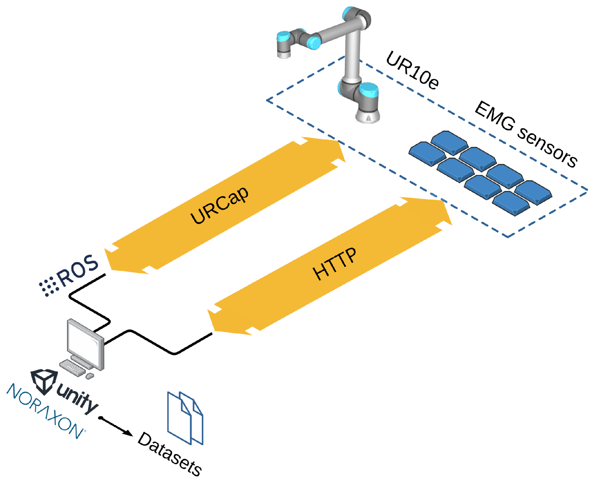
The developed software framework is designed to gather data from various sources, visualize these data, and create datasets to process them efficiently. To this end, the core manager of the framework runs in Unity and the robot data and control run in ROS. To visualise data in the UI and automatically create datasets, Unity and ROS require an intermediate communication interface. On the ROS side, two threads are in charge of the robot: one thread continuously publishes joint values, TCP position and speed, and detected force and torque to the corresponding topics; meanwhile, another is responsible for the robot control loop, which requires communication with Unity to update the robot’s resistance to movement in real-time.
On the Unity side, the Unity Robotics Hub package has been imported, allowing for the creation of custom scripts that act as ROS nodes. Consequently, two components have been created: one for publishing data and another for subscribing data. This setup enables ROS and Unity to communicate through topics. Robot data are published at a frequency of 100 Hz concurrently with the execution of the control loop at 500 Hz, thereby regulating the velocity reference in the robot’s TCP. Unity retrieves and processes these data in real time, displaying the values in the UI and storing them to construct a dataset with the robot information. This dataset includes details such as the patient’s code, age, gender, arm to rehabilitate, arm length, and robot resistance value. For each batch of robot data obtained in Unity, information is stored in the following format: timestamp, joints, TCP position, TCP speed, force, and the active target, which varies according to the selected game and its corresponding set of targets.
Regarding the EMG sensors, they are managed through the official Noraxon software (Noraxon MR 3.20.68 version). To obtain EMG data in Unity, the sensors placed on the patient are activated to start publishing information about muscular activation in mV. These data are captured via HTTP streaming with the help of Noraxon software carrying out HTTP requests. When a request is made, a batch of all the data stored between the previous and current requests is received. For this reason, although the sensors publish data at 2000 Hz, Unity does not receive data at this frequency due to the slower HTTP request process, necessitating further processing.
Synchronisation of both the robot and EMG datasets is achieved thanks to ROS timestamps. Each collected batch is labelled with the latest ROS timestamp immediately after the HTTP request, then resampled to 1500 Hz and interpolated to ensure sufficient temporal equidistance for performance analysis. After collecting and processing EMG data, a new dataset is automatically created. This dataset includes the original timestamp, the interpolated-resampled timestamp, and information from the eight channels, where the EMG signals are delivered in raw format to allow for maximum flexibility during postprocessing. This approach enables the offline application of customised filtering, rectification, and smoothing techniques tailored to the specific analysis objectives and patient characteristics.
As a result of the previous processes, two datasets in CSV format are delivered to the therapist after completing a rehabilitation routine, as depicted in Figure 2. The robot dataset provides real-time information on the patient’s hand position, speed, and applied force, while the EMG dataset contains information on the patient’s electrical activity. Furthermore, the framework allows the user to select the export path and the information to be included in the dataset. By default, all available information is exported.

2.3. User Interaction

Developing accurate robot control and acquiring data from the hand’s position, applied force, robot parameters, and EMG data would be pointless without proper interaction between the therapist, patient, and system. It is essential to equip the therapist with the necessary tools to understand how these data correlate with the conducted routine as well as to enable the system to receive inputs from the therapist to customise the exercises. Additionally, visual feedback is provided to the patient in order to facilitate the association between movements in the real space executed through the robot and the movements of objects in the games. Consequently, a comprehensive UI of the software framework has been developed in Unity.

2.3.1. User Interface

The main UI, integrated in C# within Unity, serves as the principal link between all the framework components: the robot, EMG sensors, therapist, and patient. It handles core data processing, synchronisation, and routine management in the back-end, while the front-end provides the therapist with all the necessary configurations to set up the routine.
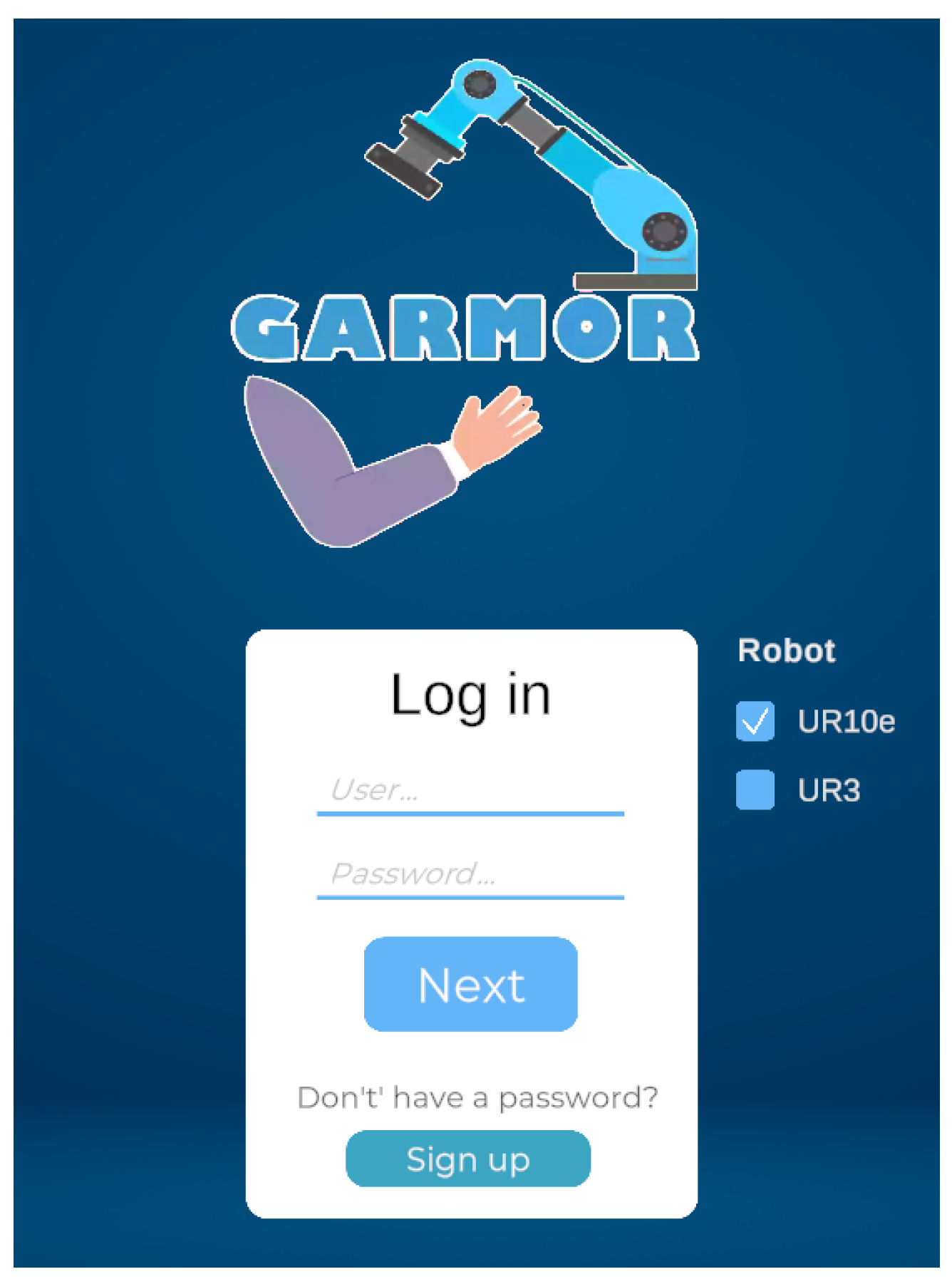
Regarding the front-end, it has been designed with a minimalist and user-friendly style, as providing an intuitive interface can ease the therapist’s experience while using the framework. It is divided into two main scenes. The first scene contains the login screen (Figure 3), where it is possible to register a new patient or initialise a session. The benefit of having a login interface is that it allows the storage of repetitive data across different sessions with various patients, such as name, age, exercise, or robot configuration. These data are only accessible by the therapist, who logs in with a unique ID and password for each patient. Additionally, because the proposed framework supports the use of various robots, the UR3 (as described in [31]) and UR10e models (available in the lab) can be seen in the image. Therefore, the login screen also offers the possibility of choosing a robot among the displayed options.
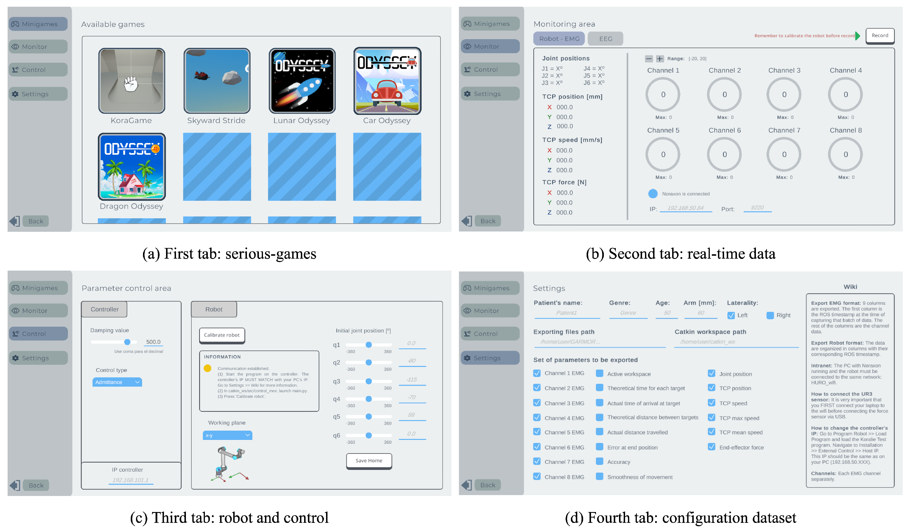
After logging in, the second main scene displays all available configurations and games included in the framework. It is subdivided into four tabs according to the content section. The first tab (Figure 4a) presents a mosaic of all serious games for the therapist to choose from and start the rehabilitation process. Each game has been developed in a separate scene, allowing for future expansion of the serious games repository. Although the games are presented in separate scenes, they all share the components responsible for managing the robots and the sensors, which were developed intentionally to enable switching between games within the same session.
The second tab (Figure 4b) offers a real-time view of all data stored in the datasets, including data related to the robot’s position in Cartesian and joint space, velocity, force at the TCP, and values from the EMG sensors. Additionally, the recording of data can be started and stopped through this tab without selecting a serious game; doing so initialises the admittance control and data exchange without gamification, leaving the therapist in charge of indicating the movements.
The third tab (Figure 4c) contains configurations related to the robot and admittance control. Here, the therapist can select the level of resistance the robot will apply, which communicates with the controller in ROS and adjusts the system’s damping value. There is also a button for calibrating the robot. This button measures the force and torque while the robot is stationary in order to subtract it from the real force in the admittance control. Moreover, the default admittance control operates in free space; however, certain serious games may require restricting motion to one axis. Consequently, a drop-down menu has been added to this tab in order to select the plane in which the robot should move (XY, YZ, or XZ), using the robot’s base as the reference system. For reference, a visual representation of the selected plane is shown just below the menu.
The last tab (Figure 4d) allows for the configuration of parameters related to the patient’s data and the datasets’ export path. It is possible to add or remove information from these datasets prior to their creation; for example, the joint position or a certain muscle can be excluded from the dataset generation. These configurations are automatically stored for each patient, and do not need to be re-entered in subsequent sessions with that patient.
Using the previous tabs, the therapist can navigate through the framework, customise the exercises according to the patient’s needs, and record data freely without following any game. There is no need to worry about starting the robot or storing the dataset, as these tasks are managed automatically. Regarding user interaction, all buttons and pressable items provide feedback, such as changing colour or enlarging. Additionally, messages inform the therapist about the current state of the systems. If the robot is not calibrated and a data recording is initiated, startup is not allowed and the therapist is informed of this through a pop-up message.

2.3.2. Gamification

Even though the main UI provides basic interaction with the framework, its primary objectives are to verify the correct functionality of the system, configure data related to the patient and routines, and select the serious game that will be used. The actual rehabilitation exercises are based on one of the provided serious games, which can be selected in the first tab and redirect the user to a new Unity scene (see Figure 4a). Currently, the application offers three games:
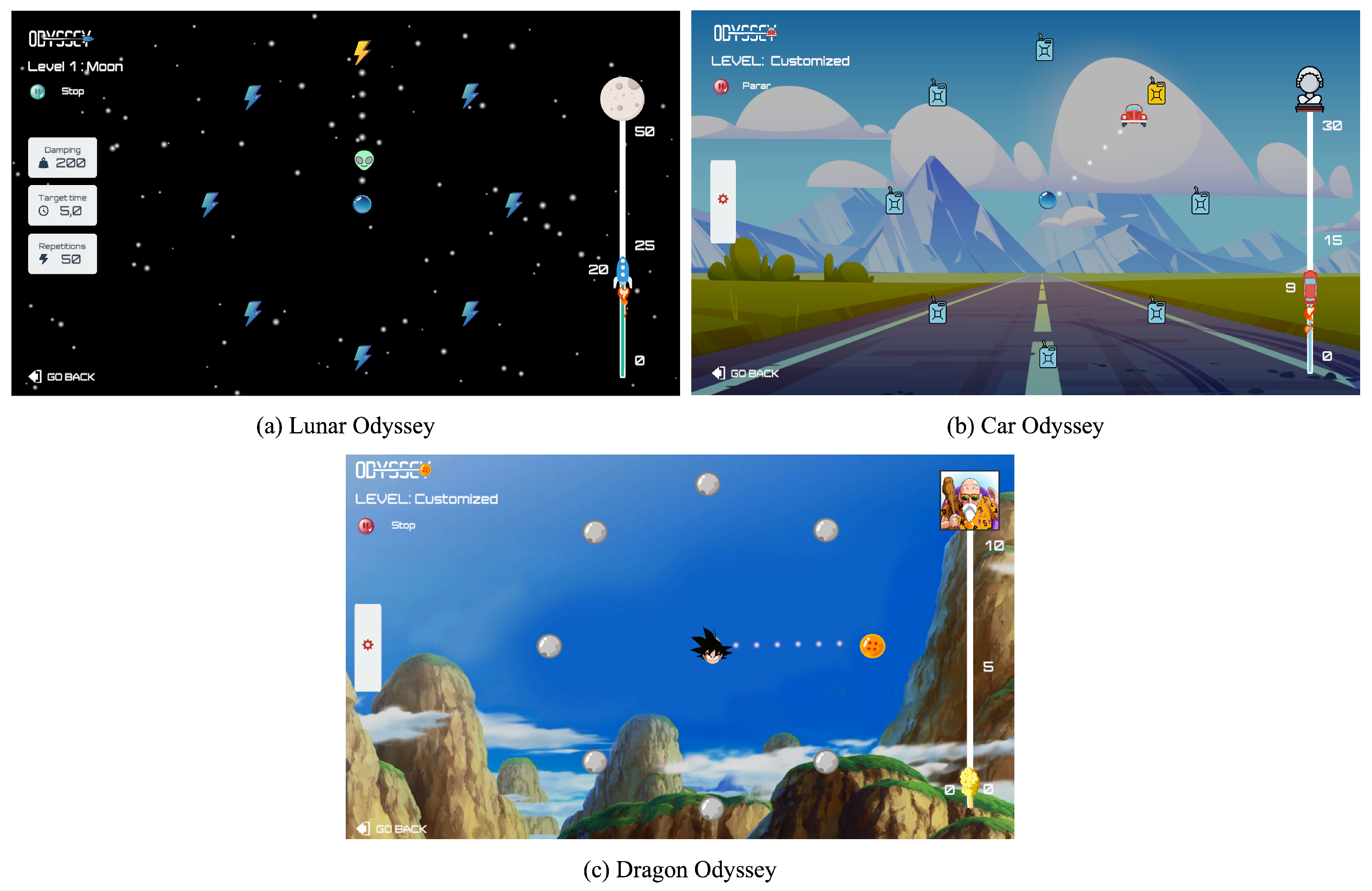
  • Odyssey is based on a centre-out approach [32] in which the patient moves the end-effector to reach targets shown on the screen. Eight targets are placed along a circular path, with one target in the centre, making for a total of nine targets. The objective is to move from the centre target to one of the targets on the circumference and then return. Depending on the user, the order of these targets can be randomised or arranged in a clockwise sequence, an option that can be selected in the game’s UI. If the user is a healthy individual, targets can be either randomised or set in a clockwise order. Randomising the targets prevents the user from learning patterns and keeps them constantly focused on the exercise. The target order is set clockwise if the user is an upper-limb rehabilitation patient, since a known sequence is easier to follow and ensures the same number of repetitions in all eight directions. There are three skins for this game: Lunar Odyssey, Car Odyssey, and Dragon Odyssey (Figure 5).
  • Skyward Stride consists of an aeroplane that flies through an infinite world in a 2D environment with obstacles to be avoided. The user can change the height of the aeroplane to deal with the obstacles, obtain bonus items, and finish different levels with variable difficulty. For upper-limb rehabilitation, the movements can be controlled by linear displacements on a plane (arm reaching) or commanded by single joint movements of the wrist or elbow.
  • Kora Game allows for rehabilitation of the upper limb as the patient moves the end-effector of the robot with admittance control. In this game, the movements of the robot are mapped to a 2D hand that collects apples and pears appearing randomly in a forest, which is as large as the robot’s working space. Different difficulty levels can be set by changing the number of fruits that appear or the maximum time for the user to grasp them.

2.4. Configuration

There are a total of six different parameters that can be used to properly tune the rehabilitation activities in Odyssey:
  • The first parameter is the user’s arm length, which is essential for adjusting the robot’s targets to match the user’s maximum arm reach. This measurement is entered into the game, which automatically adjusts the robot’s targets to ensure that the arm is fully extended and not flexed when reaching a target. The targets are mapped in an elliptic shape that allows for full arm extension when reaching them in the movement, where left–right movements have a greater range than forward–backward movements. This design ensures that the patient performs the exercise and stretches the arm to the maximum range in order to reach each target.
  • The second personalisation parameter is the robot’s plane of work. Odyssey can be used in two different planes, namely, the transverse and the frontal planes, with the human body as the frame of reference. This allows the rehabilitation exercise to be executed with either horizontal or vertical movements. In both planes, targets are adjusted according to the arm length.
  • Third, the damping value for the admittance control is adjusted for each patient. This parameter can be adjusted from 0 to 600 Ns/m in individual exercises or in consecutive exercises with a specific damping for each level. For healthy individuals, it can be set to a high value, causing the robot to provide significant resistance to movement. For rehabilitation patients, the resistance can initially be set to zero and gradually increased as rehabilitation progresses. This refinement and selection of the damping value is modified by the person in charge of the rehabilitation routine, and can be updated at any time during the exercises. When exporting data, the current damping value during the exercise is also stored.
  • Another relevant parameter is the number of repetitions required to complete the current game level. One repetition consists of two movements: one from the centre to the active target on the circumference, and a second from the target back to the centre. Visual feedback is implemented in a progress repetition bar (see Figure 5, right side of the visual interface). The number of repetitions depends on the exercise’s purpose and the patient’s resilience, and must be configured by the therapist.
  • The damping value and number of repetitions alone are not enough to define the specific speed at which the exercise should be performed. Consequently, the reaching time for each target is constantly measured, and can also be modified. If the user does not reach the target in time, it turns red and a message appears indicating the need to increase speed for the next repetition. When a target is not reached, it is not counted as a successful target. The total number of achieved or failed targets is stored in the generated robot dataset.
  • Keeping the patient motivated is an essential aspect of rehabilitation. For this reason, the sixth personalisation parameter is the game skin. Three different themes have been designed: a space adventure (Figure 5a), a driving journey (Figure 5b), and a skin inspired by the Dragon Ball anime show (Figure 5c). This allows the user to choose the theme they prefer before starting rehabilitation.
Furthermore, the game provides two modes of play: level-based and fully customised. The level-based mode consists of six levels with all parameters pre-set except for one, which changes with each level. For example, when evaluating the speed, the time allowed to reach the targets decreases with each level. The number of repetitions and the damping value can also be adjusted through the levels. It is the responsibility of the person in charge of the therapy to adapt the levels to the patient. The benefit of the level-based mode is its gamification, providing rewards for succeeding in each level. Therefore, the second gaming mode is the personalised mode, in which all parameters can be modified in real time.

2.5. Safety and Hardware Requirements

As the developed framework communicates via ROS and the robot controller, safety stops and parameter limits are configured directly on the robot controller, in this case the UR10e teach pendant, which is installed on the same computer as the framework. Certain parameter limits are configured directly in the robot controller program. These limits include workspace plane thresholds related to the user’s arm length, the target location, and the maximum force and velocity thresholds (107 N and 250 mm/s). When any of these limits is reached, a safety stop occurs within 200 ms. The robot can be restarted through the controller, and the framework resumes when communication is restored. When a communication loss of more than 250 ms is detected or power loss occurs, the framework console displays warning and error messages and the robot stops at the last detected coordinate position. The robot can be resumed through the controller. The only safety stop that requires restarting both the robot and the framework is the one triggered manually by the Z-stop.
System requirements for installing the proposed framework include an Ethernet connection on the same network used for both the robot and the computer station. The computer station should run Ubuntu 20.04.6 LTS and ROS for robot control and visualization. For the EMG acquisition system, the software should be compatible with the operating system on the computer station. If this is not the case, another computer can be used to handle the communication. It also needs to be connected to the same network as the main computer station through Ethernet or WiFi.

3. Validation Methodology

To demonstrate the feasibility of the proposed framework, a pilot evaluation was conducted involving eight healthy participants performing upper limb movements using the UR10e robot. The primary goal of this pilot was to assess the correct functioning of the framework components, robot control, EMG acquisition, gamification interface, and data synchronisation rather than to test a particular clinical hypothesis.

3.1. Experiment Protocol

In this experiment, the participants (Table 2) performed reaching movements while seated upright with feet flat on the floor and the elbow positioned at 90°. The task involved moving an object from a central position to one of eight radial targets arranged in clockwise order, then returning to the centre in the x–y plane. Following a one-minute resting baseline and a familiarization trial at 100 Ns/m, which were excluded from the analysis, each participant completed one repetition set of the eight movements at three damping levels of 200, 400, and 600 Ns/m (D200, D400, D600 respectively), with a one-minute rest period between damping levels. Participants were asked to try to maintain consistent velocity throughout all movements and damping levels. The experiment started with measurement of the participant’s dominant arm length. The chair was adjusted so that when the participant grasped the end effector, the arm was aligned with the central target of the centre-out tasks depicted in Figure 5.
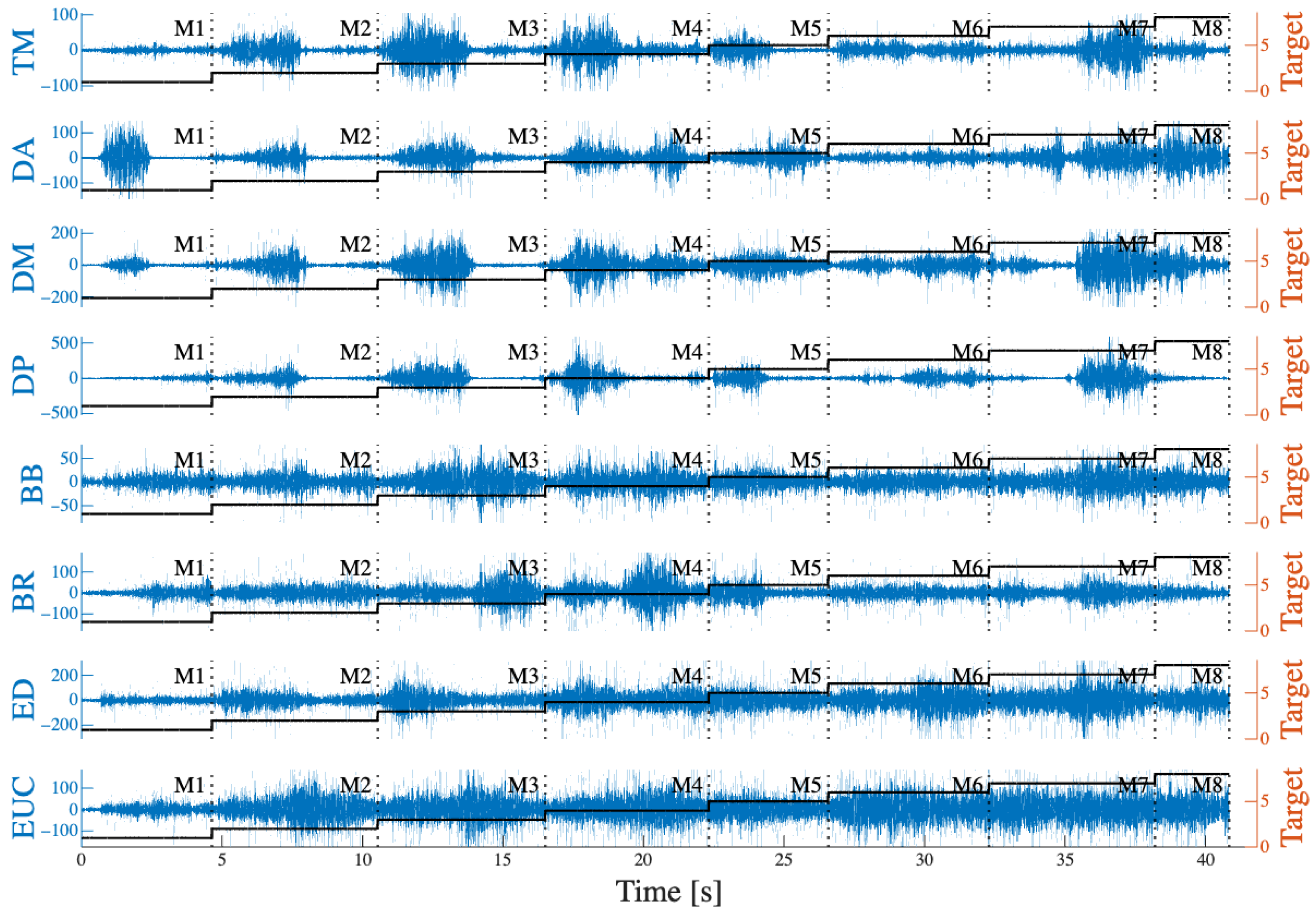
Eight EMG sensors were placed on the skin surface over the following muscles: Middle Trapezius (MT), Anterior, Middle, and Posterior Deltoid (AD, AM, AP), Biceps Brachii (BB), Brachioradialis (BR), Extensor Digitorum (ED), and Extensor Carpi Ulnaris (CUE). An example of recorded EMG signals for one set of movements is shown in Figure 6.
The game was then configured according to each participant’s data, particularly arm length. Each participant selected a preferred game skin to perform the task. The reaching time was set to 5 s; otherwise, it was considered a failure. Visual feedback of target failure was presented with a failure message appearing at the target to reach; the colour and shape of both the target and the avatar icon changed, the progress bar did not count the failed target, and at the end of the session the progress bar showed only the total number of targets reached. To minimize variability and initial fatigue, participants were asked to abstain from caffeine on test day, avoid upper limb exercise the day before, and ensure at least seven hours of sleep before testing (see Table 2). The protocol was approved by the Research Ethics Committee of the University of Alicante, with file number UA-2023-01-23 2.

3.2. Data Analysis

Because the framework provides two datasets, namely, kinematics and EMG, we performed two offline analyses. For the kinematic data, the system recorded the TCP positions, velocities, and forces in the x–y plane as well as the active target at each time point. The first milliseconds of each recording were discarded in order to remove initial adaptation to the robot’s movement. The data were then segmented into eight movements (M) for each damping level. The absolute magnitudes of force and velocity were calculated for all segments. The comparison of mean force across participants was normalised to the 95th percentile of force across all damping conditions. Time was measured as the total duration required to complete a movement, from centre to target to centre. For TCP positions, trajectory segments were compared with an ideal path, defined as the shortest path between the centre point and the objective target. Based on this comparison, errors were calculated and normalised to the corresponding movement distance: mean absolute error (MAE), maximum error (MaxE), and percentage root mean square error (PRMSE).
For the EMG data, the signals underwent multistage processing. First, outliers exceeding three times the standard deviation were removed and replaced with the median value of the window using a Hampel filter with a temporal window of 0.05 · f s . Baseline noise was subtracted, then a fourth-order Butterworth notch filter was applied to remove power line interference at 50 Hz and its harmonics. Cardiac noise in the back and shoulder channels (MT, AD, MD, PD) was subtracted from the signal using an adaptive filter. Finally, a 20 to 350 Hz bandpass filter was applied to remove low and high frequency noise. To segment muscle activity for each movement, kinematic data were interpolated and then aligned with the corresponding timestamps. Muscle activation periods were detected from the signal envelope whenever the amplitude exceeded two times the standard deviation for at least 500 ms. Within the active periods of each repetition, the root mean square (RMS) and the mean frequency (MNF) were computed using a 250-ms sliding window with 50% overlap.

4. Results

Validation of the proposed rehabilitation platform was performed with the Odyssey game. To support personalized therapy for each individual, the system incorporates different personalisation parameters that can be updated in both the main UI and within the game. The developed framework was preliminary tested with eight healthy subjects in order to validate the data acquisition process and overall system functionality as well as to assess possible kinematic metrics for evaluating user performance.

4.1. System Usability

To validate system’s usability in real-life scenarios, maximum forces and velocities were obtained. Figure 7 shows the maximum force (A) and velocity (B) values across all movement tasks. As mentioned in Section 2.5, force and velocity have limit thresholds to ensure correct robot functionality. Maximum force values for almost all subjects remained within safe limits. Notably, S06 (the subject with the longest arm length) and S07 (the youngest male subject) both showed peak values close to the force threshold. In both cases, the maximum force was observed at D400 and the lowest velocity at D600, while S06 also reported the highest velocity at D400 and S07’s velocity decreased with increasing damping, as expected. In the case of S07, this may be because the highest velocity was observed at D200, which was considerably faster than any other subject; from this initial damping level, the subject tried to maintain the same velocity across all damping levels, inducing more force than necessary through the robot. In addition, all male subjects showed higher variability in velocity, which may be due to different velocities across movements. This phenomenon may improve with a reminder to the subjects to maintain constant velocities, thereby reducing force peaks.
Figure 6 shows muscle synchronization with kinematic targets for all eight muscles. Certain targets activate muscles at the beginning of the task (centre-target), while others produce more activation at the end of the task (target-centre) and still others maintain muscle activation through the entire reach. For example, as expected, DM and DP activated at the beginning of M5, as the subject performed a downward rotation of the shoulder, while AD became more active in the middle of the task as the user performed a shoulder abduction.

4.2. User Performance

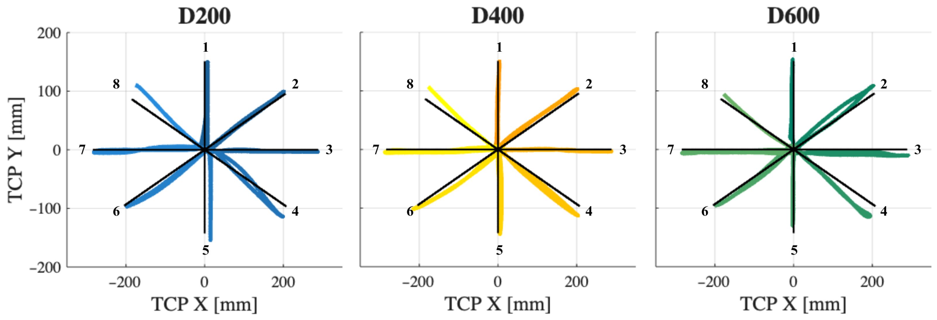
To show the trajectory performance, Figure 8 displays the expected and real TCP trajectories for all eight movements at each damping condition in the x–y plane for S02. The blue plot corresponds to the first damping level (D200), the yellow plot corresponds to the middle level (D400), and the green plot corresponds to the last level (D600). In all three plots, the dark line is the ideal trajectory. To differentiate the eight movements, each direction is represented with a gradient of its corresponding colour. In this subject, at D200 the trajectories appear inaccurate in almost all directions, while at D400 they show more precise movements with straighter paths.
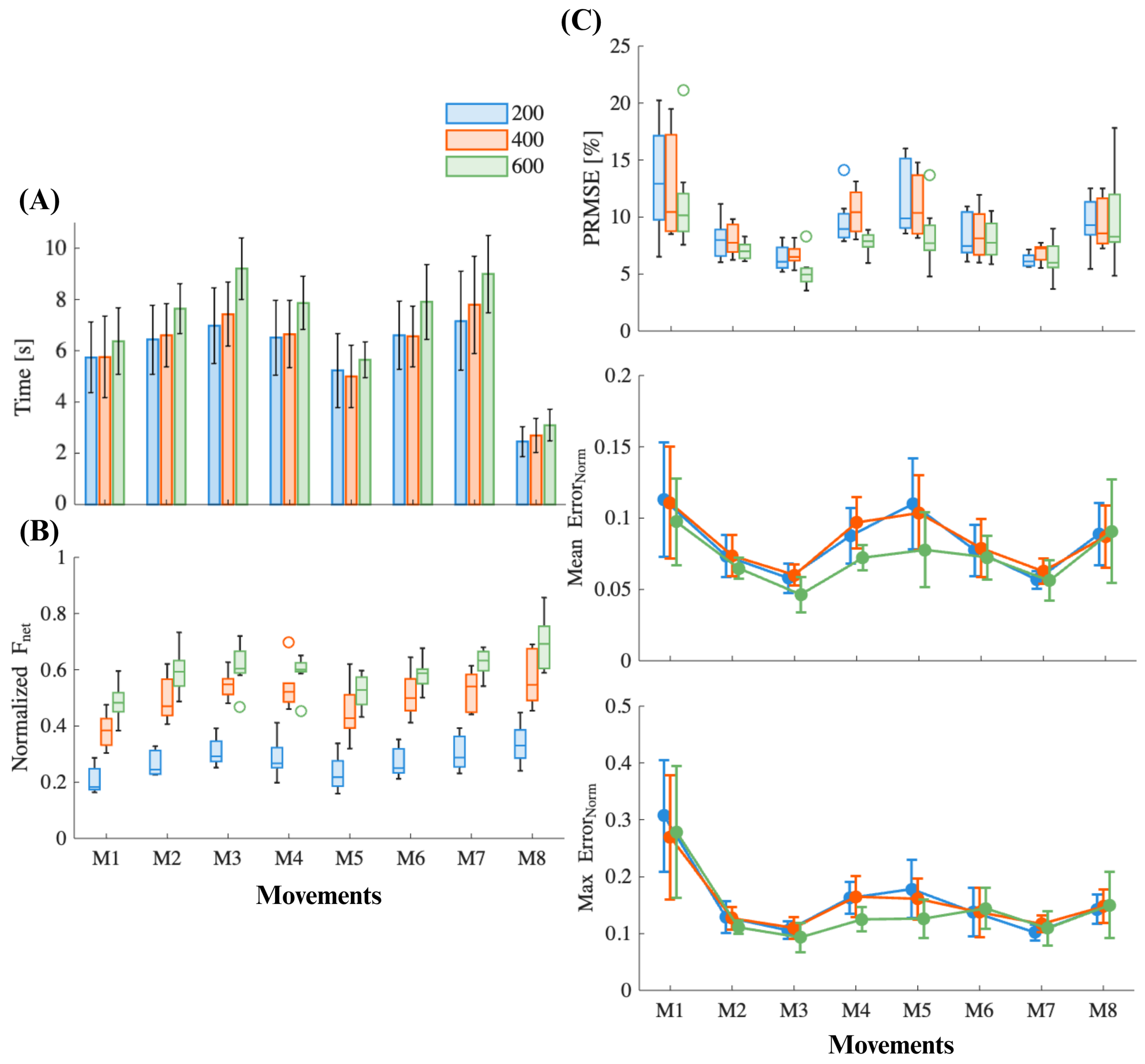
To measure the movement performance in the eight trajectories, kinematic metric plots were generated to compare movements, as shown in Figure 9. To maintain consistency between figures, results for D200 are shown in blue, for D400 in orange, and for D600 in green. Figure 9A shows a bar plot of the mean total time for each movement across all subjects. In general, time increases with higher movement resistance generated by the robot, as expected. It is important to note that while M5 and M8 have the lowest times, the difference between these two is nearly double. This is because the movement performed in the last direction was only centre-to-target, resulting in approximately half the time relative to the other movements, which were centre–target–centre. In addition, the movements with the highest times were M3 and M7, which correspond to the lateral targets, as described in Figure 8.
Regarding force values, Figure 9B shows a box plot of the normalised force across all movements. Force medians are clearly separated by damping condition, as expected: D600 > D400 > D200, which confirms that the framework applies graded mechanical resistance. The results for force also shows a directional pattern, with lateral and diagonal targets (M2, M3, M4, M6, M7, and M8) having higher values compared to vertical targets.
Performance was also analysed using movement errors. Figure 9C shows the plots for the PRMSE, mean error, and maximum error. The PRMSE values are small overall, typically between approximately 5 to 15% of the movement distance. In most directions, the PRMSE tends to be slightly lower at D600 and the movement accuracy varies between directions, with vertical targets showing the largest errors. The mean error is clustered around 0.05 to 0.12, with minimal separation between resistance levels. Interestingly, all subjects reported that M3 and M7 were the most difficult movements, yet these have the lowest errors across metrics, while M1 and M5 were reported as the easiest but have the highest errors and highest variability between subjects.
For the eight-muscle channel EMG data, normalised RMS values between 0 and 1 were computed, with values near 1 representing the session maximum. Figure 10 shows heatmaps for the three damping conditions of the normalised RMS values. The x-axis corresponds to the movement number and the y-axis to the muscles. As expected, the normalised RMS increases with damping across all directions. The proximal shoulder muscles show anatomically consistent directional tuning. The AD peaks in anterior and left anterolateral reaches (M1, M7, and M8), while the MD and PD peak in lateral movements (M3, M4, M6, and M7). The MT peaks in right lateral reaches (M2, M3, and M4) and in the left lateral movement (M7). This pattern is preserved as the load increases. Elbow flexors (BB, BR) show moderate diagonal biased recruitment that scales with damping, with the exception of M8. Distal extensors (ED, ECU) increase broadly, which indicates wrist and hand stabilization through co-contraction. Overall, M3, M6, and M7 activate all muscles more in the higher damping conditions. Figure 11 shows the mean MNF values for S02 across the three damping conditions, scaled to the maximum MNF value recorded during the protocol for each muscle. As the protocol was not sufficiently demanding to induce fatigue, no significant changes in MNF values were consistently observed in all subjects.

5. Discussion

The primary objective of the pilot study was to assess the feasibility of the proposed framework in a real environment with different subjects and subject characteristics. For this reason, the analysis focused primarily on the visualisation and interpretation of the data generated by the system rather than on a detailed evaluation of the participants’ performance. Within the context of the present study, the most relevant aspects were the correct synchronisation of data, effective communication between the various system modules (Unity, ROS, and EMG), and functional validation of the complete framework. Preliminary results, particularly the RMS values obtained from the EMG signals, demonstrated that the system responds appropriately: as damping increases, there is a proportional rise in muscle activation, accompanied by an increase in the applied forces and an expected reduction in execution speed. With respect to trajectory errors, a decreasing trend was observed as the damping level increased. However, because only one set of eight movements was performed per damping level, this trend could be attributed either to motor adaptation or to the possibility that higher damping facilitates the execution of more stable and linear trajectories in the absence of fatigue.
The developed framework enables linear movements in the x–y and y–z planes, allowing tasks with up to four degrees of freedom. This primarily targets the shoulder and elbow, although the wrist may also benefit to some extent. Moreover, the system can be extended to support three-dimensional movements provided that compatible skins are developed to accommodate this functionality. In comparison with other robotic rehabilitation platforms for the upper limb, the present system offers capabilities similar to recent technologies that support 3D interaction, such as the Armeo family [25], Gentle/s, and Proficio devices. In contrast, earlier systems such as ARM-Guided and MIT-Manus are limited to movements with one or two degrees of freedom, respectively [33]. A key aspect to consider is post-session feedback. Most current rehabilitation robots provide only basic kinematic metrics; some offer performance indicators at the end of the therapy session, as is the case with the Proficio [34]. However, EMG signals are typically excluded from this type of performance analysis, being used mainly for device control rather than as quantifiable indicators of the patient’s condition or progression [28].

Future Work and Current Limitations

While this work has demonstrated the technical feasibility of the proposed framework in controlled settings with healthy participants and ROS-compatible collaborative robots from the UR family, further studies are required to fully validate its applicability in broader rehabilitation contexts. Future work should focus on conducting clinical trials with at least ten ABI patients with a minimum of three hours per week and a total of five sessions [33] in order to assess the effectiveness of the framework in real rehabilitation scenarios. This study would include assessment of impact on motor recovery outcomes, user engagement, and therapist usability. Analysis of both kinematic data and EMG recordings should be addressed in order to provide patients with a complete overview of the therapy sessions, which should include movement performance with error metrics such as PRMSE, MaxE, and MAE along with muscle strengthening with force and velocity metrics for the kinematic analysis and fatigue and muscle power for the EMG analysis. At the end of the therapy, a complete report including patient score and improvement should be provided.
Additionally, further experiments are planned to implement and validate the framework on other ROS-compatible robots beyond the Universal Robots family. This would help to confirm the framework’s adaptability to diverse hardware platforms and configurations. To support wider adoption, collaborative efforts with external research groups are envisioned, allowing independent teams to deploy and evaluate the system in different environments. Furthermore, we intend to expand the gamification module with more personalized and adaptive tasks as well as to integrate biosignal processing pipelines for user feedback, since one of the main limitations of the current framework is the lack of real-time feedback. At present, only time feedback is provided through changes in target colour, a failure message, and a progress bar that does not count missed targets. Markers such as fatigue detection, large increases in error, and messages about force and velocity when values approach their limits are key objectives for future online analysis. A kinematic report should also be provided at the end of the session instead of raw kinematic and EMG data. Finally, regarding data privacy and long-term management, measures should include implementation of end-to-end encryption and multifactor authentication across data capture, transmission, and storage as well as integration of automated pseudonymization and legally compliant retention policies supported by immutable audit trails for full traceability.

6. Conclusions

This paper has presented a robotic framework designed for upper-limb rehabilitation in ABI patients. The proposed framework offers an adaptable solution for rehabilitation exercises integrating data acquisition, serious games to enhance patient engagement, and flexible robot control options. A technical validation of the framework was carried out in a controlled setting with eight healthy participants and three different damping conditions with an ROS-compatible collaborative robot from the UR family, demonstrating the feasibility and functionality of the proposed framework as a proof of concept.

Author Contributions

A.C. and N.S. contributed to data curation, formal analysis, investigation, and writing. Both also participated in reviewing and editing along with C.R. Study methodology and software development was the principal contribution of N.S., with the help of K.P. in software development. A.U. and C.A.J. provided supervision and contributed to writing and reviewing of the article. All authors have read and agreed to the published version of the manuscript.

Funding

This work is part of the GARMOR project, reference PID2022139105OB-I00, funded by the Ministry of Science, Innovation and Universities (MCIN/AEI/10.13039/501100011033).

Institutional Review Board Statement

This study has ethical approval from the Research Ethics Committee of the University of Alicante, file number UA-2023-01-23 2.

Informed Consent Statement

Informed consent was obtained from all subjects involved in the study.

Data Availability Statement

The datasets and materials are available upon request to the corresponding author.

Conflicts of Interest

The authors declare no conflicts of interest.

Abbreviations

The following abbreviations are used in this manuscript:
ABIAcquired Brain Injury
ROSRobot Operating System
EMGElectromyography
URUniversal Robots
DoFDegrees of Freedom
UIUser Interface
HTTPHypertext Transfer Protocol
CSVComma-Separated Values

References

  1. Zorowitz, R.D.; Chen, E.; Tong, K.B.; Laouri, M. Costs and Rehabilitation Use of Stroke Survivors: A Retrospective Study of Medicare Beneficiaries. Top. Stroke Rehabil. 2009, 16, 309–320. [Google Scholar] [CrossRef]
  2. Aprile, I.; Germanotta, M.; Cruciani, A.; Loreti, S.; Pecchioli, C.; Cecchi, F.; Montesano, A.; Galeri, S.; Diverio, M.; Falsini, C.; et al. Upper Limb Robotic Rehabilitation after Stroke: A Multicenter, Randomized Clinical Trial. J. Neurol. Phys. Ther. 2020, 44, 3–14. [Google Scholar] [CrossRef] [PubMed]
  3. Kennard, M.; Hassan, M.; Shimizu, Y.; Suzuki, K. Max Well-Being: A Modular Platform for the Gamification of Rehabilitation. Front. Robot. AI 2024, 11, 1382157. [Google Scholar] [CrossRef]
  4. Krebs, H.I.; Hogan, N.; Aisen, M.L.; Volpe, B.T. Robot-aided Neurorehabilitation. IEEE Trans. Rehabil. Eng. 1998, 6, 75–87. [Google Scholar] [CrossRef]
  5. Lum, P.S.; Burgar, C.G.; Shor, P.C.; Majmundar, M.; Van der Loos, M. Robot-assisted Movement Training Compared with Conventional Therapy Techniques for the Rehabilitation of Upper-limb Motor Function after Stroke. Arch. Phys. Med. Rehabil. 2002, 83, 952–959. [Google Scholar] [CrossRef]
  6. Richardson, R.; Brown, M.; Bhakta, M.; Levesley, M.C. Design and Control of a Three Degree of Freedom Pneumatic Physiotherapy Robot. Robotica 2003, 21, 589–604. [Google Scholar] [CrossRef]
  7. Reinkensmeyer, D.J.; Kahn, L.E.; Averbuch, M.; McKenna-Cole, A.N.; Schmit, B.D.; Rymer, W.Z. Understanding and Treating Arm Movement Impairment after Chronic Brain Injury: Progress with the ARM Guide. J. Rehabil. Res. Dev. 2000, 37, 653–662. [Google Scholar]
  8. Zhu, T.L.; Klein, J.; Dual, S.A.; Leong, T.C.; Burdet, E. ReachMAN2: A Compact Rehabilitation Robot to Train Reaching and Manipulation. In Proceedings of the 2014 IEEE/RSJ International Conference on Intelligent Robots and Systems, Chicago, IL, USA, 14–18 September 2014; pp. 2107–2113. [Google Scholar] [CrossRef]
  9. Chiriatti, G.; Palmieri, G.; Palpacelli, M.C. A Framework for the Study of Human-robot Collaboration in Rehabilitation Practices. In Advances in Service and Industrial Robotics, Proceedings of the International Conference on Robotics in Alpe-Adria Danube Region, Kaiserslautern, Germany, 19 June 2020; Springer: Cham, Switzerland, 2020; pp. 190–198. [Google Scholar] [CrossRef]
  10. Rodrigues, J.C.; Menezes, P.; Restivo, M.T. An Augmented Reality Interface to Control a Collaborative Robot in Rehab: A Preliminary Usability Evaluation. Front. Digit. Health 2023, 5, 1–16. [Google Scholar] [CrossRef]
  11. Molteni, F.; Gasperini, G.; Cannaviello, G.; Guanziroli, E. Exoskeleton and End-Effector Robots for Upper and Lower Limbs Rehabilitation: Narrative Review. Innov. Influenc. Phys. Med. Rehabil. 2018, 10, 174–188. [Google Scholar] [CrossRef] [PubMed]
  12. Garro, F.; Chiappalone, M.; Buccelli, S.; De Michieli, L.; Semprini, M. Neuromechanical Biomarkers for Robotic Neurorehabilitation. Front. Neurorobot. 2021, 15, 742163. [Google Scholar] [CrossRef] [PubMed]
  13. Lencioni, T.; Fornia, L.; Bowman, T.; Marzegan, A.; Caronni, A.; Turolla, A.; Jonsdottir, J.; Carpinella, I.; Ferrarin, M. A Randomized Controlled Trial on the Effects Induced by Robot-assisted and Usual-care Rehabilitation on Upper Limb Muscle Synergies in Post-stroke Subjects. Sci. Rep. 2021, 11, 5323. [Google Scholar] [CrossRef] [PubMed]
  14. Huang, C.; Chen, M.; Zhang, Y.; Li, S.; Zhou, P. Model-based Analysis of Muscle Strength and EMG-force Relation with Respect to Different Patterns of Motor Unit Loss. Neural Plast. 2021, 2021, 5513224. [Google Scholar] [CrossRef] [PubMed]
  15. Goffredo, M.; Proietti, S.; Pournajaf, S.; Galafate, D.; Ciota, M.; Le Pera, D.; Posterato, F.; Francesichini, M. Baseline Robot-measured Kinematic Metrics Predict Discharge Rehabilitation Outcomes in Individuals with Subacute Stroke. Front. Bioeng. Biotechnol. 2022, 10, 1012544. [Google Scholar] [CrossRef] [PubMed]
  16. Afyouni, I.; Rehman, F.U.; Qamar, A.M.; Ghani, S.; Hussain, S.O.; Sadiq, B.; Rahman, M.A.; Murad, A.; Basalamah, S. A Therapy-driven Gamification Framework for Hand Rehabilitation. User Model. User-Adapt. Interact. 2017, 27, 215–265. [Google Scholar] [CrossRef]
  17. Simić, M.; Stojanović, G.M. Wearable Device for Personalized EMG Feedback-based Treatments. Results Eng. 2024, 23, 102472. [Google Scholar] [CrossRef]
  18. Alfieri, F.M.; da Silva Dias, C.; de Oliveira, N.C.; Battistella, L.R. Gamification in Musculoskeletal Rehabilitation. Curr. Rev. Musculoskelet. Med. 2022, 15, 629–636. [Google Scholar] [CrossRef]
  19. Tuah, N.M.; Ahmedy, F.; Gani, A.; Yong, L.N. A Survey on Gamification for Health Rehabilitation Care: Applications, Opportunities, and Open Challenges. Information 2021, 12, 91. [Google Scholar] [CrossRef]
  20. Faran, S.; Einav, O.; Yoeli, D.; Kerzhner, M.; Geva, D.; Magnazi, G.; van Kaick, S.; Mauritz, K.-H. Reo Assessment to Guide the ReoGo Therapy: Reliability and Validity of Novel Robotic Scores. In Proceedings of the 2009 Virtual Rehabilitation International Conference, Haifa, Israel, 29 June–2 July 2009. [Google Scholar] [CrossRef]
  21. Exoskeleton Report, “Upper Body Fixed Rehabilitation: Exoskeleton Catalog Category for Upper Body Fixed (or Stationary) Wearable Exoskeletons”. Available online: https://exoskeletonreport.com/product-category/exoskeletoncatalog/medical/upper-body-fixed-rehabilitation/ (accessed on 19 November 2023).
  22. Nexum by Wearable Robotics. Available online: https://nexumrobotics.it/ (accessed on 19 November 2023).
  23. D’Antonio, E.; Galofaro, E.; Patane, F.; Casadio, M.; Masia, L. A Dual Arm Haptic Exoskeleton for Dynamically Coupled Manipulation. In Proceedings of the 2021 IEEE/ASME International Conference on Advanced Intelligent Mechatronics (AIM), Delft, The Netherlands, 12–16 July 2021; IEEE: Delft, The Netherlands, 2021; pp. 1237–1242. [Google Scholar]
  24. Calabrò, R.S.; Russo, M.; Naro, A.; Milardi, D.; Balletta, T.; Leo, A.; Filoni, S.; Bramanti, P. Who May Benefit From Armeo Power Treatment? A Neurophysiological Approach to Predict Neurorehabilitation Outcomes. PM&R 2016, 8, 971–978. [Google Scholar] [CrossRef]
  25. Calabrò, R.S. (Ed.) Translational Neurorehabilitation: Brain, Behavior and Technology; Springer International Publishing: Cham, Switzerland, 2024. [Google Scholar] [CrossRef]
  26. Hsieh, Y.; Lin, K.; Wu, C.; Shih, T.; Li, M.; Chen, C. Comparison of Proximal versus Distal Upper-Limb Robotic Rehabilitation on Motor Performance after Stroke: A Cluster Controlled Trial. Sci. Rep. 2018, 8, 2091. [Google Scholar] [CrossRef]
  27. Zhang, L.; Guo, S.; Sun, Q. An Assist-as-Needed Controller for Passive, Assistant, Active, and Resistive Robot-Aided Rehabilitation Training of the Upper Extremity. Appl. Sci. 2021, 11, 340. [Google Scholar] [CrossRef]
  28. Guatibonza, A.; Solaque, L.; Velasco, A.; Peñuela, L. Assistive Robotics for Upper Limb Physical Rehabilitation: A Systematic Review and Future Prospects. Chin. J. Mech. Eng. 2024, 37, 69. [Google Scholar] [CrossRef]
  29. Bessler, J.; Prange-Lasonder, G.B.; Schaake, L.; Saenz, J.F.; Bidard, C.; Fassi, I.; Valori, M.; Lassen, A.B.; Buurke, J.H. Safety Assessment of Rehabilitation Robots: A Review Identifying Safety Skills and Current Knowledge Gaps. Front. Robot. AI 2021, 8, 602878. [Google Scholar] [CrossRef] [PubMed]
  30. Shoaib, M.; Asadi, E.; Cheong, J.; Bab-Hadiashar, A. Cable Driven Rehabilitation Robots: Comparison of Applications and Control Strategies. IEEE Access 2021, 9, 110396–110420. [Google Scholar] [CrossRef]
  31. Mamani, W.; Sempere, N.; Casanova, A.; Morell, V.; Jara, C.A.; Ubeda, A. Upper Limb EMG-based Fatigue Estimation During End Effector Robot-assisted Activities. In Converging Clinical and Engineering Research on Neurorehabilitation V, Proceedings of the International Conference on NeuroRehabilitation, La Granja, Spain, 4–7 November 2024; Springer: Cham, Switzerland, 2024; pp. 441–445. [Google Scholar] [CrossRef]
  32. Rohrer, B.; Fasoli, S.; Krebs, H.I.; Hughes, R.; Volpe, B.; Frontera, W.R.; Stein, J.; Hogan, N. Movement Smoothness Changes During Stroke Recovery. J. Neurosci. 2002, 22, 8297–8304. [Google Scholar] [CrossRef]
  33. Mahfouz, D.M.; Shehata, O.M.; Morgan, E.I.; Arrichiello, F. A Comprehensive Review of Control Challenges and Methods in End-Effector Upper-Limb Rehabilitation Robots. Robotics 2024, 13, 181. [Google Scholar] [CrossRef]
  34. Abdel Majeed, Y.; Awadalla, S.; Patton, J.L. Effects of Robot Viscous Forces on Arm Movements in Chronic Stroke Survivors: A Randomized Crossover Study. J. NeuroEng. Rehabil. 2020, 17, 156. [Google Scholar] [CrossRef] [PubMed]
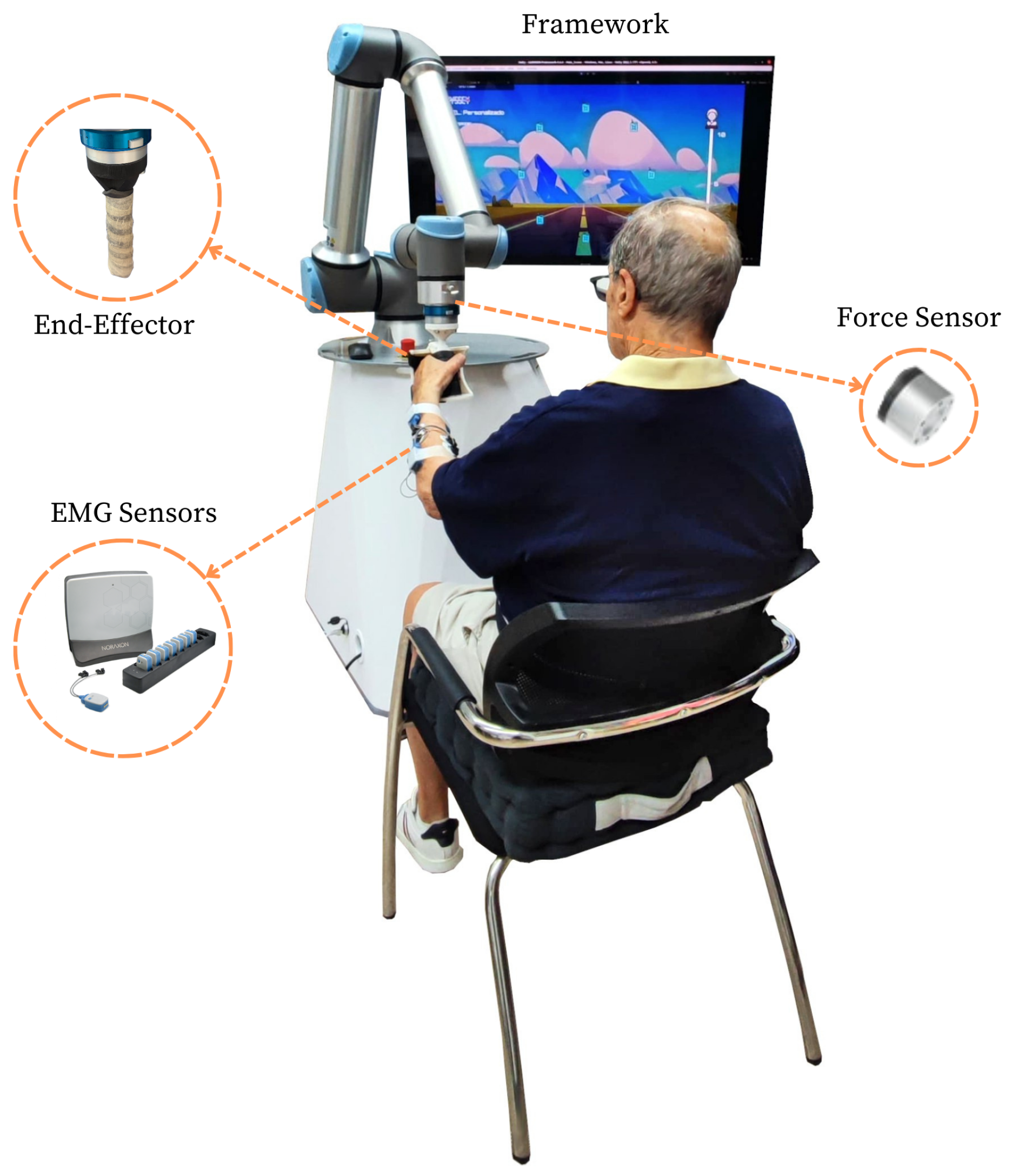
Figure 1. Setup with the robot, EMG sensors, screen, end-effector, and a participant.
Applsci 15 11007 g001
Figure 2. Diagram of data acquisition.
Applsci 15 11007 g002
Figure 3. Login screen in the proposed framework.
Applsci 15 11007 g003
Figure 4. Different tabs of the user interface.
Applsci 15 11007 g004
Figure 5. Different tabs of the game interface.
Applsci 15 11007 g005
Figure 6. EMG data synchronization of eight different muscles activity (blue) during the movement execution of the eight different targets (black) on the first level.
Applsci 15 11007 g006
Figure 7. Boxplots showing the maximum net force (A) and net velocity (B) detected in all eight subjects for each damping level. The x-axis shows the subject ID, while the y-axis shows the corresponding metric and units. All plots show D200 in blue, D400 in orange, and D600 in green.
Applsci 15 11007 g007
Figure 8. End-effector trajectories at all three damping levels for user A.
Applsci 15 11007 g008
Figure 9. Kinematics plots of the subjects’ performance across the different movements and damping conditions, showing the average time to complete a target movement (A), the normalised net force used in each movement (B), and the mean normalised errors (PRMSE, mean error, and maximum error) obtained in each movement (C). The x-axis represents the movement number, and all plots show D200 in blue, D400 in orange, and D600 in green.
Applsci 15 11007 g009
Figure 10. Mean normalised RMS values for all subjects across the eight muscles, eight movements, and three damping levels.
Applsci 15 11007 g010
Figure 11. Mean MNF values for subject S02, scaled to the maximum value for each muscle across all eight movements and all three damping levels. The x-axis corresponds to the movement number and associated damping level. Black zones indicate periods with no detected muscle activation.
Applsci 15 11007 g011
Table 1. Commercial upper-limb rehabilitation robots.
RobotAim 1Training 2 ModesGamificationData 3
ALEx SS-EPK
ALEx RSS-E-FA-W-+VRK
ArmeoPowerS-E-H *P+VR-
ArmeoSpringS-E-H *-K
ArmeoSpring ProS-E-H *-K
Harmony SHRS-EP + Ass--
Nx-A2S-E-H-+VRK
ReoGoS *-E-WP + AssK
Yidong-Arm1S-E-HP, A, M--
REAPlanS-EAdap-
InMotion ArmS-E-HAdapIE-K
* If requested. 1 (S) Shoulder, (E) elbow, (H) hand, (FA) forearm, (W) wrist. 2 (P) Passive, (A) active, (M) mixed, (Ass) assistive, (Adp) adaptative. 3 (K) Kinematic, (IE) intelligent evaluation.
Table 2. Description of the healthy subjects.
Subject IDSexAgeArm Length (mm)Sleep Time
S01F225407 h
S02F274607 h
S03M245607 h
S04F234907 h
S05M395607 h
S06M475807 h
S07M215307 h
S08F24460<5 h
All participants were right-handed.
Disclaimer/Publisher’s Note: The statements, opinions and data contained in all publications are solely those of the individual author(s) and contributor(s) and not of MDPI and/or the editor(s). MDPI and/or the editor(s) disclaim responsibility for any injury to people or property resulting from any ideas, methods, instructions or products referred to in the content.