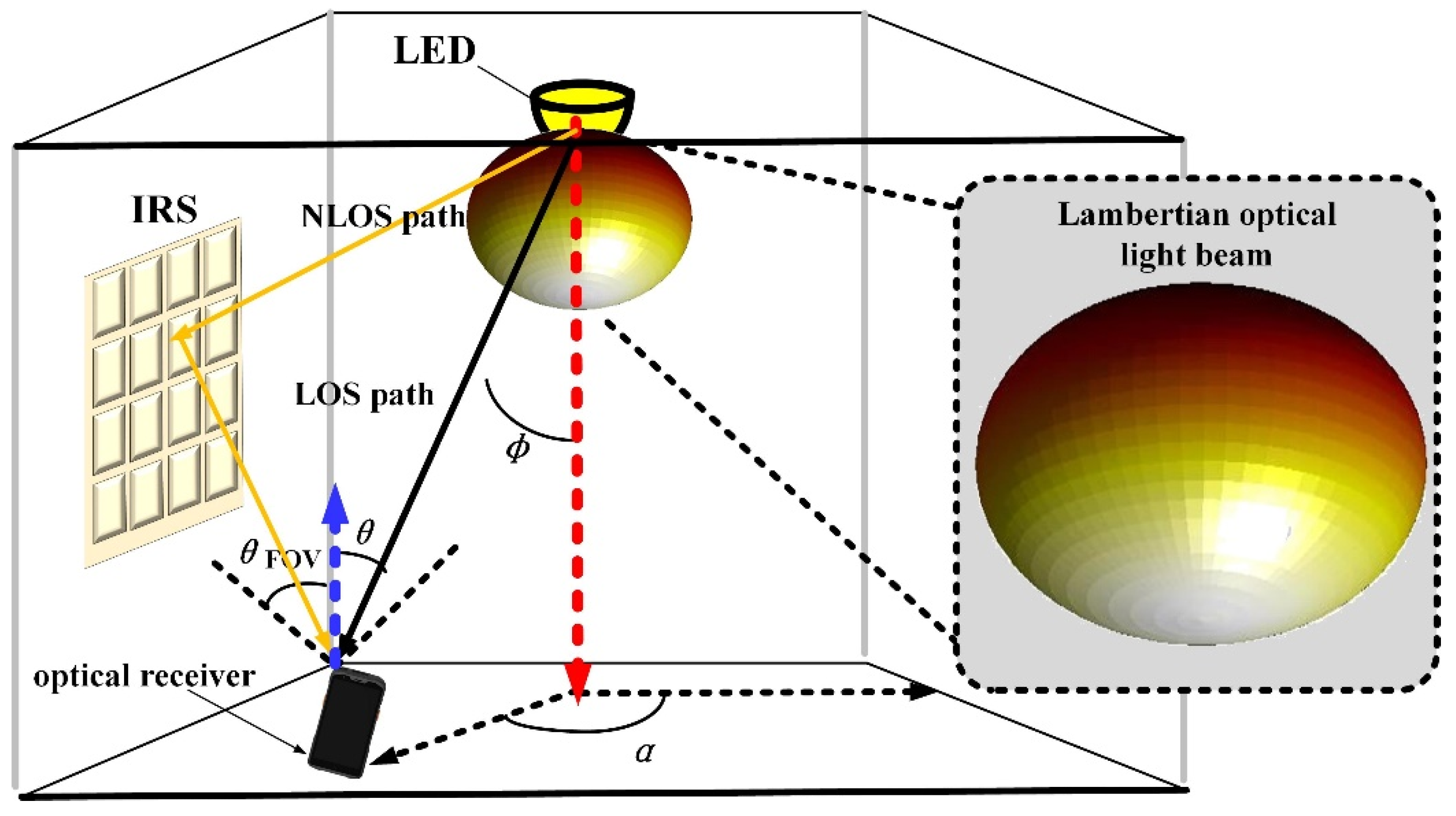
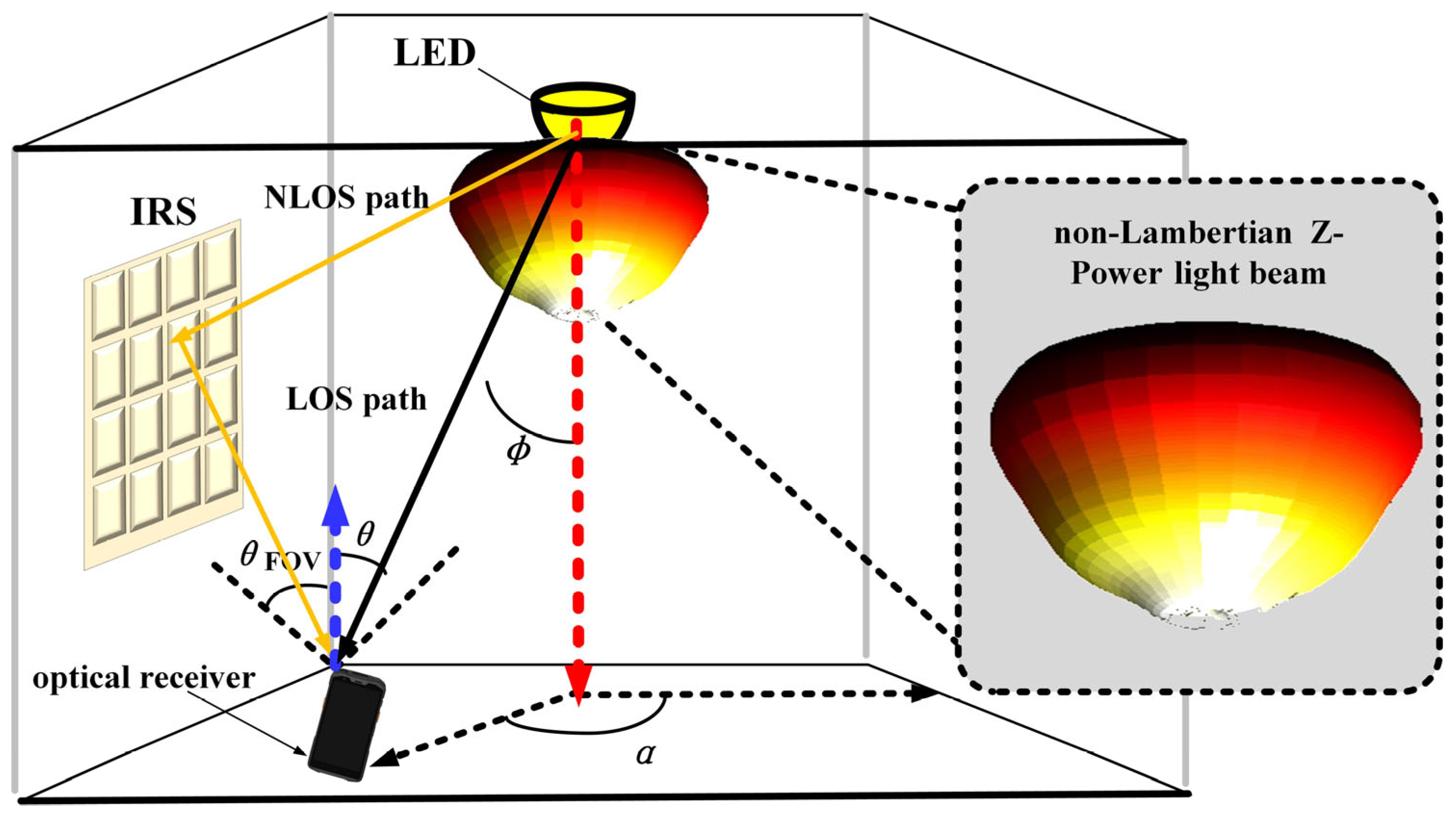
In this section, to maintain consistency with the scenarios shown in
Figure 1,
Figure 2 and
Figure 3, a typical indoor scenario is inherited to investigate the LED beam’s effects on the performance of IRS-assisted VLC, except for the involved LED radiation beam. And for fair comparison, all concerned non-Lambertian radiation patterns are normalized by a power normalization factor in the following work of IRS-assisted VLC. Furthermore,
Table 1 summarizes the main parameters for the following distinct spatial beam-based, IRS-assisted VLC, which is mainly inherited from well-reported works [
18,
19,
20]. Without loss of generality, the central position of the light receiver, i.e., (2.5, 2.5, 0.85) m, typical side positions of the light receiver, i.e., (2.5, 0.5, 0.85) m and (0.5, 2.5, 0.85) m, and typical corner positions of the light receiver, i.e., (0.5, 0.5, 0.85) m and (4.5, 0.5, 0.85) m, are considered for the following study [
14,
15,
16].
4.1. Effect of Available Emitted Signal Power
In this subsection, the effect of the available emitted signal power on the achieved SNR performance of differentiated beam-based, IRS-assisted VLC is comparatively investigated. In the case of a central-position light receiver, as shown in
Figure 4a, when IRS assistance is absent, the initial received SNR of conventional Lambertian beam pattern-based VLC is 31.87 dB. On the other hand, if IRS assistance is available for the baseline Lambertian VLC scenario, the initial received SNR is enhanced to 34.10 dB, which means that a 2.23 dB SNR enhancement is provided by the application of an IRS. In the meantime, as for the non-Lambertian Z-Power light beam-based VLC, the initial received SNR is just 21.71 dB with the absence of IRS assistance, while the counterpart is increased to 27.42 dB with the adoption of IRS assistance. This indicates that up to a 5.71 dB SNR enhancement is provided to non-Lambertian Z-Power VLC. Then, for the non-Lambertian, asymmetric NSPW light beam-based VLC, the initial received SNR goes up to a maximum of 38.63 dB with the absence of IRS assistance. Once IRS assistance is applied, this performance metric is slightly improved to 39.87 dB, which means that only a 1.24 dB gain could be brought to the non-Lambertian NSPW VLC for the receiver central position with the best channel condition. On the other, hand, when the available emitted signal power is increased to 1000 mW from the initial 100 mW, if IRS assistance is not available, the received SNR is changed to 51.87 dB, 41.71 dB, and 58.63 dB for the baseline Lambertian, non-Lambertian Z-Power, and non-Lambertian NSPW VLC scenarios, respectively, while this performance metric is separately varied to 54.10 dB, 47.42 dB, and 59.87 dB if IRS assistance is available. Accordingly, the SNR gain provided by the IRS assistance is 2.23 dB, 5.71 dB, and 1.24 dB for the three VLC link configurations concerned when the final 1000 mW signal power is emitted from the LED transmitter.
As shown in
Figure 4b, for the side position case of the light receiver, due to the rotational symmetric property of the benchmark Lambertian and the novel non-Lambertian Z-Power beam, without IRS assistance, the respective SNR performance is the same for side position 1 of (2.5, 0.5, 0.85) m and side position 2 of (0.5, 2.5, 0.85) m. Specifically, if the emitted signal power is 100 mW, the received SNR is 21.04 dB and 15.88 dB for baseline Lambertian and non-Lambertian Z-Power light beam-based VLC for the two side positions simultaneously, while the received SNR at side position 1 is 16.52 dB and at side position 2 is 25.17 dB for the non-Lambertian NSPW VLC due to the rotational asymmetry of the NSPW LED beam. Once IRS assistance is applied, at side position 1, the received SNR is moderately increased to 25.34 dB, 22.50 dB, and 19.52 dB for baseline Lambertian, non-Lambertian Z-Power, and non-Lambertian NSPW VLC, respectively, since side position 1 is relatively far away from the IRS array. Therefore, the gain provided by the IRS assistance is 4.30 dB, 6.62 dB, and 3.00 dB, separately. At the same time, with IRS assistance, the received SNR of side position 2 is impressively enhanced to 38.85 dB, 38.10 dB, and 40.50 dB for the above-three VLC configurations, respectively, since side position 2 is quite close to the IRS array. When the emitted power is increased to the final 1000 mW, at side position 1, with IRS assistance, the received SNR is further increased to 45.34 dB, 42.50 dB, and 39.52 dB for baseline Lambertian, non-Lambertian Z-Power, and non-Lambertian NSPW VLC, respectively. And the derived gain from the IRS assistance is still 4.30 dB, 6.62 dB, and 3.00 dB, separately. As for side position 2 with the final emission power, the received SNR is further increased to 58.85 dB, 58.10 dB, and 60.51 dB for the above-three VLC links under IRS assistance, while the derived gain from the IRS assistance is also varied to 17.81 dB, 22.22 dB, and 15.34 dB, separately.
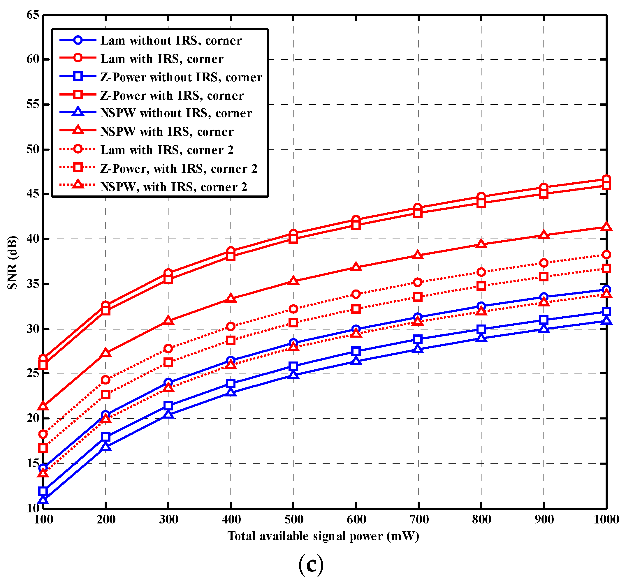
In the case of a corner-position light receiver, as shown in
Figure 4c, due to the rotational symmetry of the baseline Lambertian and the non-Lambertian Z-Power light beam, without IRS assistance, the respective SNR performance is the same for corner position 1 of (0.5, 0.5, 0.85) m and corner position 2 of (4.5, 0.5, 0.85) m. It must be noted that since the link distance of all concerned corner positions is longer than that of the above-mentioned central position and side positions of the light receiver, the overall level of the received SNR for the corner positions is lower than that of the above-discussed central position and side positions when IRS assistance is absent. Particularly, if the emitted signal power is 100 mW, the received SNR is 14.41 dB, 11.91 dB, and 10.83 dB for baseline Lambertian, non-Lambertian Z-Power light, non-Lambertian NSPW beam-based VLC for the two corner positions simultaneously. Once IRS assistance is applied, at corner position 1, the received SNR is apparently increased to 26.65 dB, 25.99 dB, and 21.32 dB for baseline Lambertian, non-Lambertian Z-Power, and non-Lambertian NSPW VLC, respectively, since corner position 1 is relatively close to the wall where the IRS array is mounted, so a more powerful transmission assist could be provided by the IRS array. In this situation, the specific gain provided by the IRS assistance is 12.24 dB, 14.08 dB, and 10.49 dB, separately. Nevertheless, with IRS assistance, the received SNR of corner position 2 is merely enhanced to 18.26 dB, 16.68 dB, and 13.89 dB for the above-three VLC configurations, respectively, since corner position 2 is much farther away from the wall where the IRS array is mounted. When the emitted power is increased to the final 1000 mW, at corner position 1, with IRS assistance, the received SNR is steadily increased to 46.65 dB, 46.00 dB, and 41.32 dB for baseline Lambertian, non-Lambertian Z-Power, and non-Lambertian NSPW VLC, respectively. And the derived gain from the IRS assistance is 12.24 dB, 14.09 dB, and 10.49 dB, separately. As for corner position 2 with the final emission power, the received SNR is varied to 38.26 dB, 36.68 dB, and 33.89 dB for the above-three VLC links with IRS assistance, while the derived gain from the IRS assistance is still limited to 3.85 dB, 4.77 dB, and 3.06 dB, separately.
The trends of the results in this subsection can be summarized as follows: For all concerned receiver positions, with the total available signal power increase, the SNR performance is accordingly enhanced, no matter the specifically adopted LED beam configuration in the IRS-assisted VLC systems. At the same time, it could be found that the NSPW LED beam-based, IRS-assisted VLC systems consistently provide the more superior SNR performance than other cases during the whole process of the available emitted signal power variation.
4.2. Effect of IRS Reflection Factor
In this subsection, the effect of the IRS reflection factor on the achieved SNR performance of differentiated beam-based, IRS-assisted VLC is comparatively investigated.
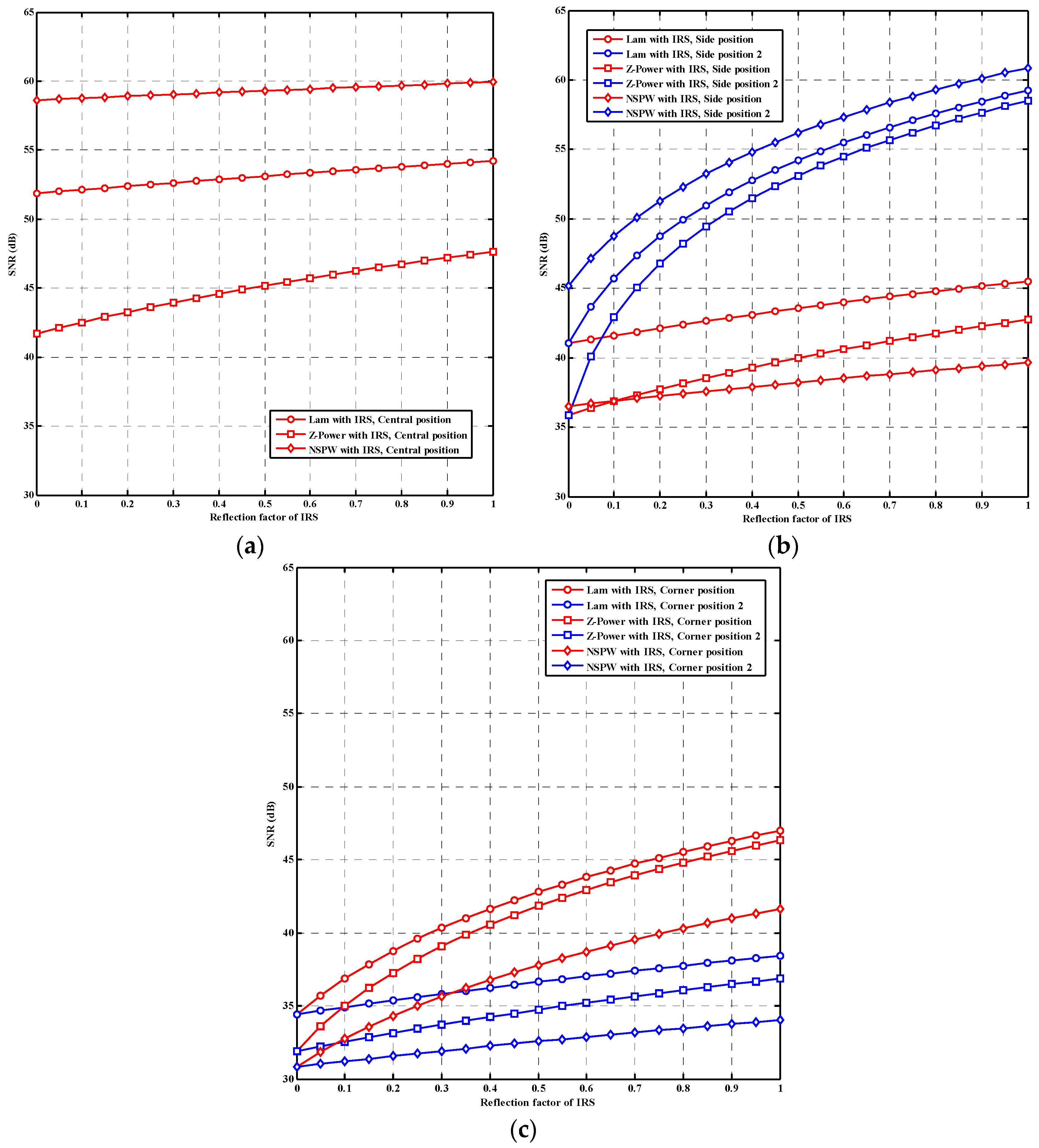
In the case of a central-position light receiver, as shown in
Figure 5a, when the reflection factor of the IRS is the initial minimum, i.e., 0, the initial received SNR for baseline Lambertian, non-Lambertian Z-Power, and non-Lambertian NSPW VLC is 51.87 dB, 41.71 dB, and 58.63 dB, separately. Once the reflection factor of the IRS is increased to the ideal maximum, i.e., 1, the received SNR of the baseline Lambertian, non-Lambertian Z-Power, and non-Lambertian NSPW VLC is enhanced to 54.20 dB, 47.64 dB, and 59.93 dB, accordingly, which means that the maximum gain achieved by the IRS is just 2.33 dB, 5.93 dB, and 1.30 dB for the three VLC configurations at the central position of the light receiver. This phenomenon is mainly due to the receiver position being just under the optical transmitter, and the relatively sufficient LoS channel gain from the LED transmitter dominates the derived SNR at the VLC receiver to a large extent.
In the case of a more challenging side-position light receiver, as shown in
Figure 5b, when the reflection factor of the IRS is the initial minimum, at both side positions, the initial received SNR for baseline Lambertian, non-Lambertian Z-Power, and non-Lambertian NSPW VLC is 41.03 dB, 35.88 dB, and 36.52 dB, separately. Once the reflection factor of the IRS is increased to the ideal maximum, i.e., 1, at side position 1, the received SNR for baseline Lambertian, non-Lambertian Z-Power, and non-Lambertian NSPW VLC is lightly enhanced to 45.52 dB, 42.74 dB, and 39.65 dB, accordingly, which means that the maximum gain achieved by the IRS is only 4.49 dB, 6.86 dB, and 3.13 dB for the three VLC configurations at side position 1 of the light receiver.
On the other hand, at side position 2, the initial received SNR for baseline Lambertian, non-Lambertian Z-Power, and non-Lambertian NSPW VLC is 41.03 dB, 35.88 dB, and 45.17 dB, separately. Once the reflection factor of the IRS is increased to the ideal maximum, at side position 2, the received SNR for baseline Lambertian, non-Lambertian Z-Power, and non-Lambertian NSPW VLC is exciting enhanced to 59.24 dB, 58.51 dB, and 60.88 dB, accordingly, which means that the maximum gain achieved by the IRS is up to 18.21 dB, 22.63 dB, and 15.71 dB for the three VLC configurations at side position 2 of the light receiver. This phenomenon is mainly due to side receiver position 2 being much closer to the IRS than side receiver position 1, while the domination of the LoS channel gain from the LED transmitter is much reduced for both side positions due to the longer LoS propagation distance between the LED transmitter and the studied two side positions, simultaneously.
In the case of the most challenging corner-position light receiver, as shown in
Figure 5c, when the reflection factor of the IRS is the minimum, at both corner positions, the initial received SNR for baseline Lambertian, non-Lambertian Z-Power, and non-Lambertian NSPW VLC is just 34.41 dB, 31.91 dB, and 30.83 dB, separately. Once the reflection factor of the IRS is increased to the ideal maximum, i.e., 1, at corner position 1, the received SNR for baseline Lambertian, non-Lambertian Z-Power, and non-Lambertian NSPW VLC is significantly enhanced to 46.99 dB, 46.35 dB, and 41.63 dB, accordingly, which means that the maximum gain achieved by the IRS is up to 12.58 dB, 14.44 dB, and 10.80 dB for the three VLC configurations at corner position 1 of the light receiver. However, at corner position 2, the received SNR for baseline Lambertian, non-Lambertian Z-Power, and non-Lambertian NSPW VLC is slightly varied to 38.42 dB, 36.87 dB, and 34.02 dB, accordingly, which means that the maximum gain achieved by the IRS is just 4.01 dB, 4.96 dB, and 3.19 dB for the three VLC configurations at corner position 2 of the light receiver. This phenomenon is mainly due to corner position 1 being relatively closer to the IRS than corner position 2, while the domination of the LoS channel gain from the LED transmitter is further reduced to both corner positions due to the maximum LoS propagation distance between the LED transmitter and the two corner positions, simultaneously.
The trends of the results in this subsection can be summarized as follows: For all concerned receiver positions, with the increase in the reflection factor of the IRS, the SNR performance is accordingly enhanced, no matter the specifically adopted LED beam configuration in the IRS-assisted VLC systems. At the same time, it could be found that for the same receiver position, the NSPW LED beam-based, IRS-assisted VLC systems consistently provide the more superior SNR performance than other cases during the whole process of the reflection factor of IRS variation. Moreover, among the concerned side positions, the SNR performance of the side position with a shorter distance to the IRS is more sensitive than the SNR performance of the side position with a longer distance to the IRS. A similar change trend could also be identified among the SNR performances of all concerned corner receiver positions.
4.3. Effect of Receiver Radial Shift
In this subsection, the effect of receiver radial shift on the achieved SNR performance of differentiated beam-based, IRS-assisted VLC is comparatively investigated.
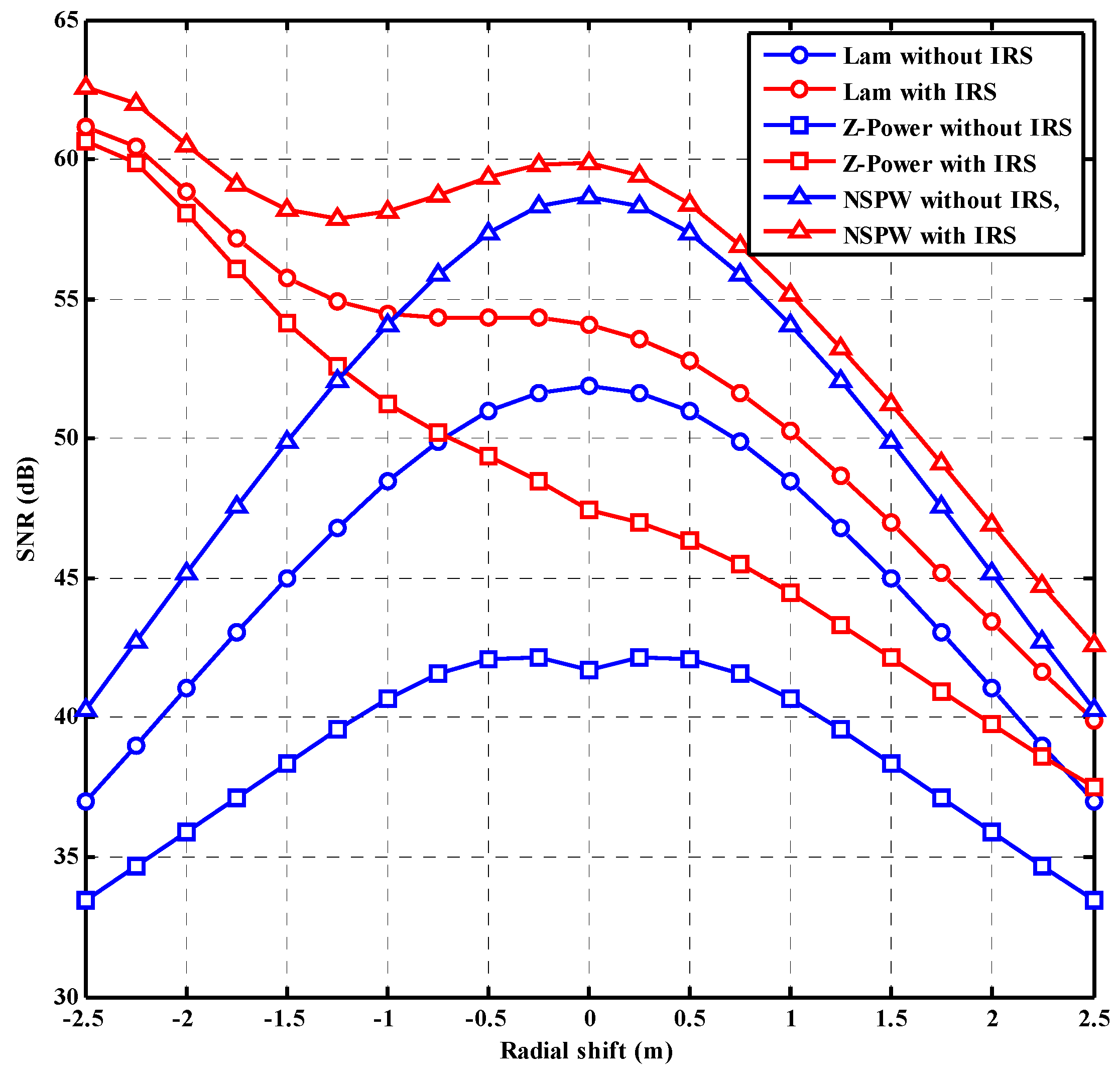
On one hand, as shown in
Figure 6, without IRS assistance, the received SNR of the initial central position of the light receiver is 51.87 dB, 41.71 dB, and 58.63 dB for baseline Lambertian, non-Lambertian Z-Power, and non-Lambertian NSPW VLC. With an increase in the radial shift of the VLC receiver along the positive or negative directions of the x-coordinate axis, the received SNR for the three VLC configurations is gradually reduced, since that the LoS channel gain from the LED transmitter is accordingly further reduced for the positions with more radial shift. Therefore, the finally minimum received SNR of 37.01 dB, 33.46 dB, and 40.27 dB could be identified for the above-three VLC configurations separately, once the radial shift of the receiver is changed to the maximum of 2.5 m along the positive or negative directions of the x-coordinate axis.
On the other hand, with IRS assistance, the received SNR of the initial central position of the light receiver is 54.10 dB, 47.42 dB, and 59.87 dB for baseline Lambertian, non-Lambertian Z-Power, and non-Lambertian NSPW VLC, which means that the initial gain given by the IRS assisting is 2.23 dB, 5.71 dB, and 1.24 dB, separately. With the increase in the radial shift of the VLC receiver along the negative direction of the x-coordinate axis, the received SNRs for baseline Lambertian and non-Lambertian Z-Power VLC are gradually varied to the respective maximums 61.17 dB and 60.66 dB, while the received SNR for the non-Lambertian NSPW VLC is varied to the local minimum 57.89 dB, with an about −1.25 m radial shift, and then increased to the maximum 62.58 dB with a final −2.5 m radial shift. This observation illustrates that a final gain of 24.16 dB, 27.20 dB, and 22.31 dB could be provided by the IRS assisting with the final radial shift along the negative direction of the x-coordinate axis; thanks to that, the spatial distance between the VLC receiver and the IRS is dramatically reduced with more radial shift along this direction.
Nevertheless, with an increase in the radial shift of the VLC receiver along the positive direction of the x-coordinate axis, the received SNRs for baseline Lambertian, non-Lambertian Z-Power, and non-Lambertian NSPW VLC are gradually reduced. This performance metric is finally varied to the minimums 39.92 dB, 37.50 dB, and 42.63 dB, with a maximum 2.5 m radial shift along the positive direction of the x-coordinate axis. Accordingly, for the above-three VLC configurations, the final limited gains of 2.91 dB, 4.04 dB, and 2.36 dB could be provided by the IRS assistance with the final positive radial shift, which is mainly due to the spatial distance between the VLC receiver and the IRS being further increased with more radial shift along this direction.
The trends of the results in this subsection can be summarized as follows: In the direction away from the IRS, with the increase in radial shift of the light receiver, the SNR performance is accordingly reduced, no matter the specifically adopted LED beam configuration in the IRS-assisted VLC systems. On the contrary, in the direction close to the IRS, with the increase in radial shift of the light receiver, the SNR performance is accordingly enhanced, no matter the specifically adopted LED beam configuration in the IRS-assisted VLC systems. At the same time, it could be found that the NSPW LED beam-based, IRS-assisted VLC systems consistently provide the more superior SNR performance than other cases during the whole process of the radial shift variation of light receiver.
4.4. Effect of Beam Azimuth Deviation
In this subsection, the effect of receiver radial shift on the achievable data rate performance of differentiated beam-based, IRS-assisted VLC is comparatively investigated. Unlike baseline Lambertian, non-Lambertian Z-Power, and other rotational symmetric LED beam-based VLC systems, the link performance of non-Lambertian NSPW beam-based VLC is usually related to the beam azimuth deviation induced by the actual engineering installation, customized coverage, or decoration requirements, due the inherent rotational asymmetry of this distinct LED beam.
As shown in
Figure 7, for the central position of the receiver, without IRS assistance, the achievable data rate is constant at 188.72 Mbps, since this position is just under the LED transmitter and any beam azimuth deviation could not vary the central radiation intensity, i.e., the radiation intensity in this direction of the central position. It must be noted that once IRS assistance is adopted, the achievable data rate performance of the central position will be mildly influenced periodically as well, which is mainly because the IRS-reflected channel gain is periodically changed by the azimuth deviation of the NSPW light beam, to some extent. Particularly, as the azimuth deviation angle is 0 deg., 180 deg., and 360 deg., the maximum achievable data rate, i.e., 192.84 Mbps, is derived for this central position, which means that the available maximum gain among all possible azimuth deviation angles is just 4.12 Mbps via IRS assistance.
At the same time, for the two side positions considered, a more intensive periodical change could be observed due to the introduction of different azimuth deviation angles. For side position 1, once the azimuth deviation angle is 90 deg. or 270 deg., the maximum achievable data rate, i.e., 144.00 Mbps, is derived without the IRS assisting, while this maximum achievable data rate is moderately enhanced to 154.80 Mbps with IRS assistance due to the relatively far link distance between side position 1 and the IRS array. And once the azimuth deviation angle is 0 deg., 180 deg., or 360 deg., for the same side position, the minimum achievable data rate, i.e., 115.29 Mbps, is derived without the IRS assisting, while this minimum achievable data rate is moderately enhanced to 125.232 Mbps with IRS assistance.
On the contrary, for side position 2, once the azimuth deviation angle is 90 deg. or 270 deg., the minimum achievable data rate, i.e., 115.29 Mbps, is derived without the IRS assisting, while this minimum achievable data rate is dramatically enhanced to 164.00 Mbps with IRS assistance due to the quite short link distance between side position 2 and the IRS array. And once the azimuth deviation angle is 0 deg., 180 deg., or 360 deg., for the same side position 2, the maximum achievable data rate, i.e., 144.00 Mbps, is derived without the IRS assisting, while this minimum achievable data rate is greatly enhanced to 194.95 Mbps with IRS assistance.
Last but not least, two important corner positions involved are also comparatively considered for exploring the effect of beam azimuth deviation. For corner position 1, once the azimuth deviation angle is about 40 deg. or about 230 deg., the maximum achievable data rate, i.e., 116.66 Mbps, is derived without the IRS assisting, while this maximum achievable data rate is obviously enhanced to 153.54 Mbps with IRS assistance, since corner position 1 is near the wall where the IRS array is installed. And once the azimuth deviation angle is about 130 deg. or 310 deg., for the same corner position 1, the minimum achievable data rate, i.e., 87.04 Mbps, is derived without the IRS assisting, while this minimum achievable data rate is apparently enhanced to 122.95 Mbps with IRS assistance.
Nevertheless, the benefit is not prominent anymore for the left corner position 2, due to the much longer link length between the IRS array and this challenging position. Accordingly, once the azimuth deviation angle is about 40 deg. or about 230 deg., the minimum achievable data rate, i.e., 87.04 Mbps, is derived without the IRS assisting, while this minimum achievable data rate is moderately enhanced to 97.65 Mbps with IRS assistance. And once the azimuth deviation angle is about 130 deg. or 310 deg., for the same corner position 2, the maximum achievable data rate, i.e., 116.66 Mbps, is derived without the IRS assisting, while this maximum achievable data rate is also moderately enhanced to 127.69 Mbps with IRS assistance.
The trends of the results in this subsection can be summarized as follows: For all concerned receiver positions, with the application of an IRS, the SNR performance of NSPW LED beam-based VLC systems is accordingly enhanced, no matter the specifically adopted LED beam azimuth deviation angle in the IRS-assisted VLC systems. Moreover, among the concerned receiver positions, the SNR performances of these positions with a shorter distance to the IRS illustrate more intense SNR performance fluctuations during the whole process of azimuth deviation angle variation.
As for potential Monte Carlo simulation of the topic in this article, although it utilizes the random variables to simulate the emitted optical signal and AWGN noise sample, the final obtained Monte Carlo simulation results will converge to the analytical results, which are presented in this article, once the amounts of the optical signal and AWGN noise sample are large enough. Therefore, it could be easily expected that the similar results could be obtained by the Monte Carlo simulation, which will not increase the true contribution of this article in the exploration of intelligent reflecting surface-assisted non-Lambertian visible light communication.
As for the feasibility of implementing this system, it must be noted that all the non-Lambertian beam models concerned in this article are all based on the top international work of LED beam patterns, i.e., reference [
12] by I. Moreno, who is one top well-known researcher of beam patterns of various commercially available LEDs. In addition, all the non-Lambertian models in reference [
12] are based on solid measurements and numerical modelling for the commercially available LED. Therefore, the non-Lambertian LEDs in this article are all commercially available, and the relevant datasheet information could be easily found in reference [
12], which fundamentally assures the feasibility of implementing this intelligent reflecting surface-assisted non-Lambertian visible light communication system utilizing existing hardware.
As for the challenges of implementing the IRS with non-Lambertian beams in a real-world scenario, the top challenge is the shortage of high-quality research teams with essential interdisciplinary capabilities for non-Lambertian IRS-assisted VLC. Most researchers in the VLC community could not present wide technical perspectives to simultaneously cover the cutting-edge development of illumination engineering, optical communications, photometry, and radiometry. Last but not least, a challenge is that the most national and industry funds for VLC development are not invested to the most potential and fruitful researchers or teams in the non-Lambertian VLC domain, for example, Prof. Jupeng Ding and his team.
As for the potential for further research, it must be noted that the main contributions and novelty of this article can be summarized as follows: (1) novel non-Lambertian LED sources and distinct non-Lambertian light beams are introduced in the domain of intelligent reflecting surface-assisted non-Lambertian visible light communications in a typical indoor environment; (2) the fundamental system models of the involved intelligent reflecting surface-assisted non-Lambertian visible light communications with distinct light beam patterns are presented in detail; and (3) the numerical performance comparisons and the fundamental performance gain provided by the representative intelligent reflecting surface-assisted non-Lambertian visible light communications are presented and analyzed for the first time, to the best of our knowledge. Therefore, this article could not touch all the potential research directions of this novel branch of VLC, i.e., intelligent reflecting surface-assisted non-Lambertian visible light communications. And there are many research topics waiting for further exploration, which include but are not limited to (1) multiple-access schemes for IRS-assisted non-Lambertian VLC, (2) physical-layer security for IRS-assisted non-Lambertian VLC, (3) IRS-assisted non-Lambertian vehicular VLC, (4) resource management for IRS-assisted non-Lambertian VLC, (5) resource management for IRS-assisted non-Lambertian multiple-input–multiple-output VLC, (6) IRS-assisted non-Lambertian drone VLC, and (7) IRS-assisted non-Lambertian underwater VLC.
