1. Introduction
As coal mining operations extend deeper and across wider areas, the incidence rate of diverse mining-related accidents has shown a consistent upward trend, particularly rockburst incidents; they hav been rising steadily, accompanied by a gradual escalation in their severity [
1,
2,
3]. Among them, hard roof-induced rockbursts represent a specific type, characterized by the “three-high and one-low” properties of the roof strata, which lead to the continuous accumulation of elastic energy. Once the accumulated energy exceeds a critical threshold, it can be released instantaneously, generating intense dynamic loads and significantly increasing the hazard of rockburst accidents [
4,
5,
6]. In pursuit of safe and efficient coal extraction, numerous mining operations have implemented the practice of reserving wide coal pillars between neighboring goafs. However, this approach unavoidably results in significant losses of recoverable coal resources. Therefore, it is urgent to explore alternative methods to mitigate the resource losses associated with the retention of wide coal pillars.
In response to the low recovery rate associated with traditional strip mining and the high economic cost of conventional filling mining, domestic scholars have proposed a new mining method in practice [
7,
8]. This approach involves initially conducting filling mining through a filling process. After the backfill body is compacted and acquires sufficient bearing capacity, the remaining working face is subsequently subjected to caving mining, a process referred to as strip filling mining. The integration of coal pillars and backfill materials in strip filling mining creates a composite support structure, which enables a reduction in pillar width. This approach improves coal recovery efficiency and brings notable economic advantages. Moreover, as a partial filling mining technique, strip filling mining achieves a favorable balance between filling cost and surrounding rock control, and it has emerged as one of the important mining methods in deep and complex mining areas. However, the impact hazard associated with strip filling mining remains unclear, limiting its guidance for practical engineering applications.
At present, numerous studies have confirmed that filling mining plays a positive role in preventing and controlling rockburst hazards. Hou et al. [
9] optimized the filling mining process and found that backfilling the goaf significantly improves the stability of the surrounding rock at the working face and reduces the hazard of roof deformation. Liu et al. [
10] further pointed out that increasing the filling rate can markedly suppress microseismic activity and reduce the release of energy associated with rockbursts. Liu et al. [
11] demonstrated that the filling body can effectively support intermediate coal pillars, redistribute stress, and eliminate stress concentration, thereby preventing rockburst occurrences. In addition, Liu et al. [
12] also reported that filling mining can significantly improve stress distribution and prevent rockburst accidents. Li et al. [
13] through numerical simulation and physical experiments, revealed that the combination of filling body and coal pillar can effectively control roof subsidence and prevent rockburst disasters. Guo et al. [
14] emphasized that, except under a few special conditions, increasing the filling rate can significantly mitigate impact hazards, further confirming the critical significance of filling rate in the prevention and control of impact-related disasters.
However, most existing studies concentrate on applying strip filling mining to horizontal working faces, while its use under upward mining face conditions remains insufficiently explored. In such settings, the overburden becomes more complex, stress fields more irregular, and energy accumulation and release more concealed, making traditional theories difficult to apply. Therefore, systematic investigations are needed to refine the theoretical framework and support the safe development of deep coal seams. To this end, this study selects the No. 3-3 coal seam in a Tuokexun mine as a case, aiming to analyze the impact hazard of strip filling mining in upward mining face scenarios. A comprehensive approach combining field investigation, theoretical assessment, and numerical modeling is adopted. The study focuses on examining how strip filling performs under upward conditions and aims to provide theoretical insights and technical references for its reliable implementation in complex geological settings, emphasizing its engineering significance and practical potential.
2. Engineering Overview
The No. 3-3 coal seam in a Tuokexun mine has a consistent thickness of approximately 6 m, a burial depth of about 500 m, and a dip angle of 16°. The seam is geologically stable and uniformly distributed, qualifying it for full-scale extraction. The overlying and underlying layers primarily consist of fine sandstone, with the roof and floor thicknesses measuring about 6 m and 4 m, respectively. According to assessments, the No. 3-3 seam and its immediate roof and floor demonstrate a strong propensity for rockburst events. During mining activities, multiple rockbursts have been recorded, with the most severe being the “10.30” and “9.21” incidents, which caused extensive failure in the bolt-mesh support system, ejection of coal mass, and significant deformation of the roadway.
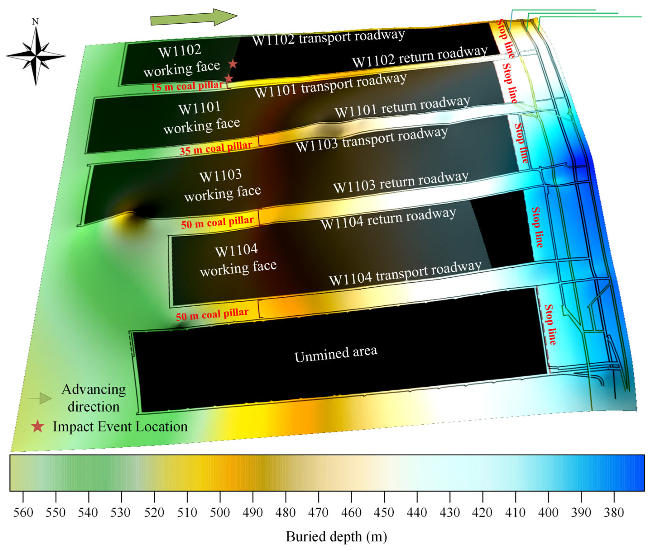
To mitigate such hazards, the mine adopted a mitigation strategy that involved progressively increasing the spacing of protective coal pillars between adjacent working faces, extending the pillar width from 15 m to 50 m, as shown in
Figure 1. Nevertheless, this adjustment led to considerable loss of recoverable coal due to over-conservative pillar dimensions.
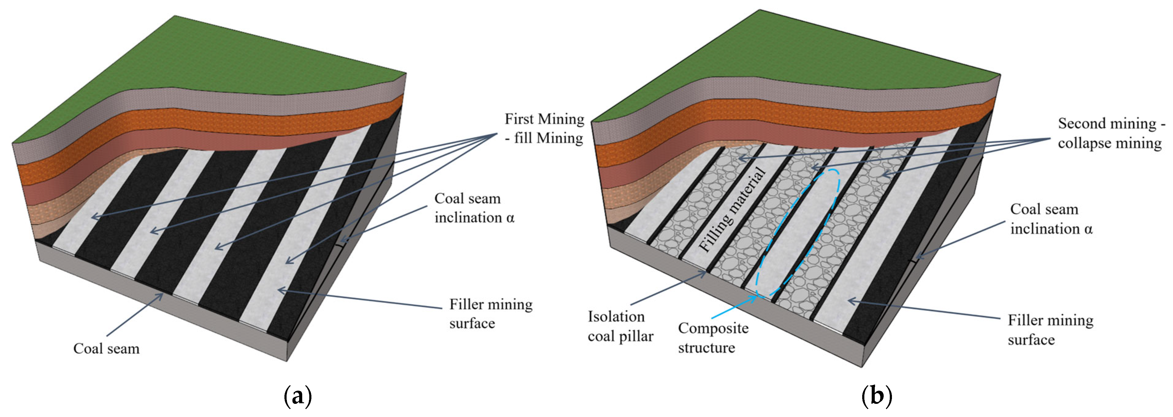
Strip filling mining, a refined approach derived from partial backfill techniques, progresses through two sequential stages: the initial stage involves backfilling operations, followed by a controlled collapse phase. This composite support structure formed during the process has been demonstrated to substantially improve coal recovery efficiency [
15,
16], as illustrated in
Figure 2. Given the increasing emphasis on operational safety and resource utilization in modern mining engineering, improving the extraction rate of coal seams has become a critical priority. Previous studies have shown that designing an isolation pillar with a standard width of 15 m can maintain structural integrity, and the corresponding overburden movement patterns have been analyzed [
17]. Nevertheless, uncertainties remain regarding the impact-related hazards of strip filling mining, which limits its broader engineering application. Based on existing findings, there is a clear need for comprehensive and in-depth studies focused on evaluating the impact hazards of strip filling mining under upward mining conditions. Such investigations carry significant theoretical and engineering value for enabling secure and efficient exploitation of deep coal resources.
3. Interaction Mechanism Between Hard Roof and Filling Bod
The backfill material plays a crucial role in maintaining the structural integrity of the goaf, as it contributes significantly to the stabilization of the mined-out area. If sufficient support is lacking during excavation, the hard roof may remain suspended for a prolonged time without collapsing, resulting in continuous elastic energy buildup and a heightened likelihood of rockburst events. The inclusion of the filling body alleviates this hazard by bearing part of the roof load, which reduces both the extent of deflection and subsidence. As a result, stress redistribution occurs, promoting a more balanced stress environment in the roof and thereby decreasing the probability of rockburst occurrences [
18]. Moreover, the synergy between the filling body and the surrounding rock gives rise to a unified structural configuration, enhancing the global stability of the rock mass and efficiently preventing delamination and fracturing of the roof layer. It is also important to note that varying the filling rate significantly impacts the deformation and failure behavior of the hard roof. The degree of control over roof stability varies noticeably depending on the specific filling rate conditions, as demonstrated in
Figure 3. Through a detailed and structured evaluation, the following key characteristics are identified [
19,
20,
21]:
- (1)
Low Filling Rate Stage: Limited Control Effect
When the filling rate is at a low level, the filling body does not effectively contact the roof before its collapse. At this stage, the roof collapse mode is similar to that of traditional caving mining, still exhibiting pronounced characteristics of periodic weighting. Only after the caved rock mass contacts the filling body does it exert a certain inhibitory effect on further subsidence, resulting in limited overall control over the roof stability.
- (2)
Medium Filling Rate Stage: Initial Control Effect
When the filling rate increases to approximately 80%, the filling body contacts the roof before its collapse and can provide a certain degree of control. However, due to the inherent compressibility of the filling material, its ability to restrain roof displacement remains insufficient to completely prevent bending deformation and local fracturing. As the working face advances, the roof may still exhibit unstable bending and fracturing behavior, accompanied by a relatively complex stress release process.
- (3)
High Filling Rate Stage: Significant Control Effect
When the filling rate surpasses 90%, nearing a completely backfilled condition, the capacity of the backfill material to provide structural support to the overlying roof strata is markedly improved. At this stage, the movement mode of the hard roof shifts from collapse to gradual bending. Periodic weighting phenomena essentially disappear, the stress release process becomes smoother, and instantaneous elastic energy release no longer occurs. Consequently, the hazard of rockburst initiation is substantially reduced, and the overall stability of the working face is effectively improved.
Once the filling body is introduced into the goaf, it establishes a stabilizing support system that significantly suppresses the displacement and fracture development of the overlying hard roof. This structural restraint plays a crucial role in maintaining the integrity of the overburden. From a mechanical perspective, a strong coupling interaction forms between the overlying roof strata and the filling material, creating a synergistic response to external loads and stress redistribution. More specifically, the filling body functions as a regulatory medium that modulates the roof’s stress field through multiple mechanisms. These include the prevention of excessive energy buildup, the buffering of abrupt energy release events, and the damping of energy transmission within the rock mass. Collectively, these effects substantially diminish the probability of rockburst hazards associated with hard roof behavior under mining-induced disturbances [
22,
23].
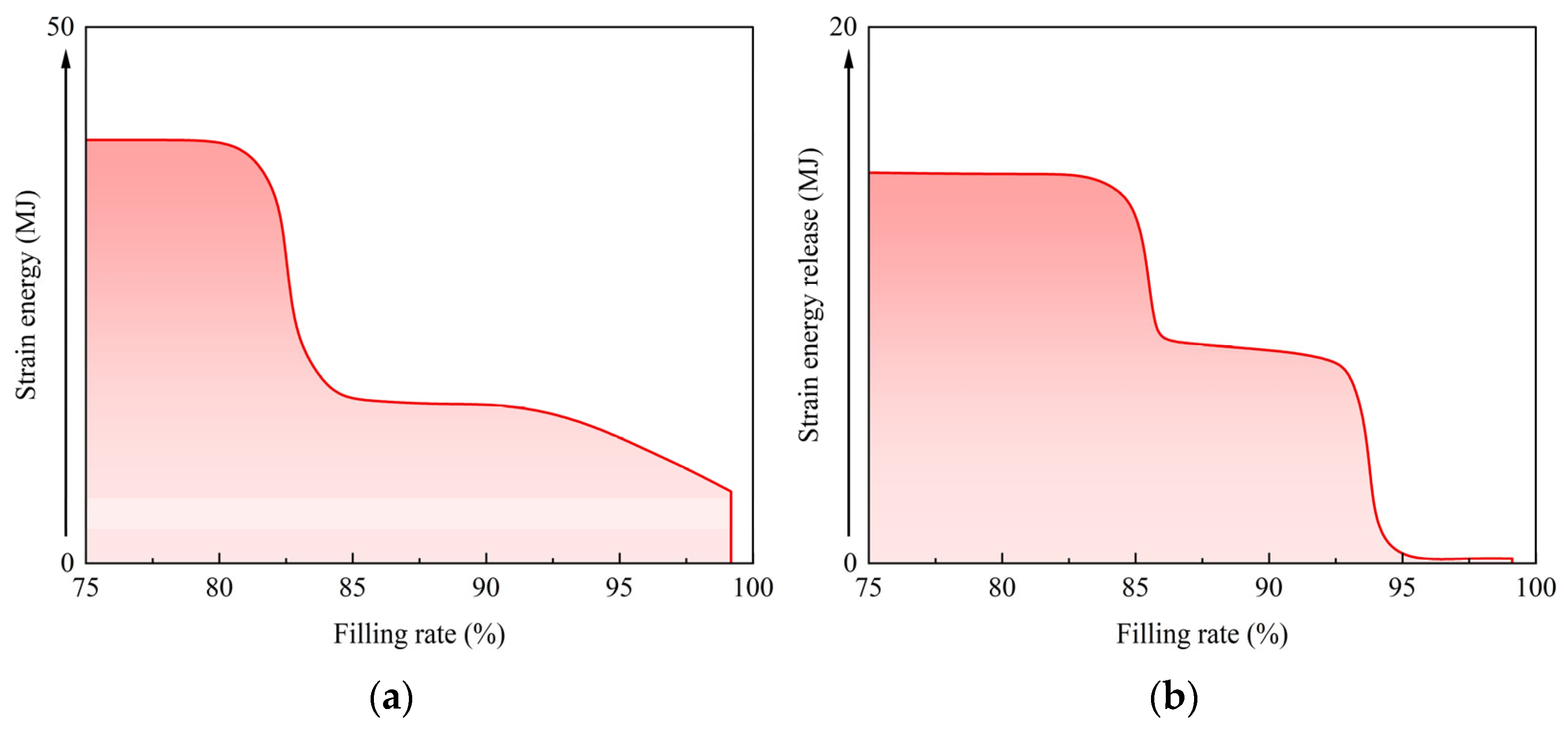
Figure 4 illustrates the relationship characteristics between elastic energy accumulation and release under different filling rate conditions. At low filling rates, energy accumulates significantly and is released abruptly, resembling conventional caving mining. At high filling rates, energy accumulation is suppressed, and the release becomes gradual due to the buffering effect of the filling body.
- (1)
Inhibition of Energy Accumulation
As the filling material gradually fills the goaf and undergoes compaction under the continuous action of the overlying load, its effect in inhibiting energy accumulation begins to manifest. Specifically, the filling body restricts the movement space of the roof, resulting in a significant reduction in the magnitude of roof displacement and a corresponding alleviation of stress concentration. Consequently, the accumulation of elastic energy induced by roof deformation is markedly weakened. This mechanism serves as one of the key factors in reducing the probability of rockburst occurrence.
- (2)
Mitigation of Energy Release
In unfilled goafs, once the hard roof fractures, a large amount of energy is often released within a short period, causing severe dynamic impacts on the surrounding coal and rock mass and even triggering rockburst events. However, the introduction of the filling body alters this process. Owing to its plastic deformation capability under compression, the filling body acts as a buffering mechanism that can slow down the rapid release rate of roof fracture energy, thereby achieving a “peak shaving” effect during the release process and enhancing the overall stability and safety of the system.
- (3)
Attenuation of Energy Transmission
The compressive strength and deformation capacity of the filling body determine its ability to absorb impact energy. Filling materials with higher resistance to deformation exhibit stronger energy absorption capacities. As the roof gradually subsides and compresses the filling body, a portion of the impact energy is absorbed and dissipated within its internal structure, effectively blocking the large-scale transmission of energy into the coal and rock mass. Results show that this process can significantly weaken the dynamic load intensity borne by the coal and rock body, serving as an effective barrier for preventing rockburst hazards.
Strip filling mining, as a representative approach of partial filling mining techniques, is designed to substitute traditional coal pillars with engineered backfill materials, enabling them to support the overburden load. This strategy not only reduces the necessity for wide retained pillars but also substantially enhances the extraction rate of coal resources by minimizing unmined protective zones. The technique is generally implemented in two phases. The initial stage involves filling mining with a relatively high filling ratio. During this stage, the roof remains largely intact, showing only minor separations or cracking. Both deformation magnitude and stress concentration are minimal, resulting in a relatively low impact hazard environment. The subsequent stage adopts a caving mining method, where roof strata collapse leads to redistribution of stress deeper into the rock mass. However, the hazard of impact events during this phase remains insufficiently understood and demands further analysis. To address these uncertainties, comprehensive investigations into the impact dynamics of strip filling mining in hard roof conditions are essential. These studies are expected to lay a solid theoretical foundation and offer targeted technical solutions for enhancing the safety and effectiveness of coal extraction under complex geological constraints.
4. Numerical Simulation Analysis of Impact Hazard
According to the “three-factor” theory, specifically the “energy source factor,” and the theory of strength weakening and impact mitigation, the primary factors inducing rockbursts can be attributed to high stress concentration and mining-induced disturbances. Reducing the degree of stress concentration, the range of displacement, and the extent of damage can effectively lower the impact hazard [
24,
25]. Based on this understanding, a comparative analysis from three aspects—stress, displacement, and plastic zone development—was conducted to examine the mine pressure evolution characteristics during the working face advancement under both the strip filling mining method and the original mining method. This analysis aims to assess the impact hazard associated with strip filling mining in upward mining face conditions.
4.1. Establishment of Numerical Model
To enable a detailed comparison of the impact potential associated with the two mining strategies, numerical simulations were performed using the FLAC3D platform. The input mechanical parameters for the models are listed in
Table 1 [
26]. The numerical models were designed based on the actual mining layout and geological conditions of the No. 3-3 coal seam. The sections were selected to: (I) Represent typical mining configurations—one with a 50 m coal pillar (conventional) and one with a 15 m pillar combined with strip filling; (II) Ensure comparability between the two methods under the same geological and mining depth conditions; and (III) Capture the stress and deformation behavior in the retreat roadway and working face under advancing excavation. These sections are representative and allow a fair comparison of mine pressure behavior. These parameters, including those for the coal seam, roof, floor, and filling material, were primarily derived from laboratory tests on core samples obtained from the mine site and were supplemented by data from previous studies conducted in similar geological settings. The geometric model for the original mining configuration (
Figure 5a) spans 420 m longitudinally, 300 m transversely, and extends 140 m vertically. Within this setup, both working faces adopt a caving mining approach, separated by a coal pillar measuring 50 m in width, while the coal seam is inclined at an angle of 16°. In contrast, the model constructed for strip filling mining (
Figure 5b) is dimensioned at 550 m in length, 300 m in width, and 120 m in height. This layout features a central working face that employs filling mining, flanked by adjacent working faces that utilize caving mining. A narrower isolation coal pillar, 15 m wide, is placed between faces, with the same seam dip angle of 16° applied. Boundary conditions were defined by setting zero displacement constraints along the side and bottom edges, whereas the top surface was considered a free boundary. Stress loading was applied to simulate real-world geological conditions.
4.2. Evolution Analysis of Advance Abutment Pressure at the Working Face
The evolution pattern of the advance abutment pressure observed under both strip filling and conventional mining methods displays a broadly consistent trend. At the initial stage, a notable surge in pressure is recorded, which subsequently stabilizes into a relatively steady condition. As illustrated in
Figure 6, within the context of the traditional mining scheme, the peak value of advance abutment pressure gradually increases with excavation progress—reaching 23.3 MPa at 60 m. Further increments to 80 m, 100 m, and 120 m correspond to successive peaks of 25.1 MPa, 27.5 MPa, and 28.9 MPa, respectively. This steady escalation in peak pressure reflects a progressive intensification of stress concentration associated with continuous excavation. In particular, the stress-affected region expands up to a distance of approximately 70 m in advance of the working face.
In contrast, the strip filling mining scenario displays a moderated pattern of abutment pressure accumulation, characterized by a less pronounced and more gradual stress increase compared to the conventional method. This pattern reflects a reduction in stress concentration and a more uniform distribution, thereby enhancing stability. Although not directly quantified by a safety factor, it implies a lower potential for dynamic failure. When the face advanced to 60 m, the recorded peak pressure was 20.3 MPa; at 80 m, it reached 21.7 MPa; at 100 m, the value increased to 22.6 MPa; and at 120 m, it climbed to 23.8 MPa. The corresponding influence zone under this method spans around 60 m. Relative to the original method, the peak abutment pressures under strip filling mining were reduced by 12.9%, 13.5%, 17.8%, and 17.6%, respectively. These comparative reductions highlight the significant efficacy of strip filling mining in alleviating stress buildup. Consequently, this method proves effective in mitigating the extent of stress accumulation near the working face, thereby reducing the likelihood of impact-related hazards during underground operations.
4.3. Mine Pressure Analysis of the Retreat Roadway at the Working Face
To examine how stress evolves within the retreat roadway during mining-induced disturbances under both mining schemes, a numerical modeling study was conducted, simulating a scenario where the working face advances 100 m from the cut eye. The focus of the analysis lies in mapping the spatial evolution of stress distribution within the surrounding rock, assessing the deformation responses, and tracking the initiation and progression of plastic zones throughout the excavation process.
- (1)
Stress distribution characteristics of the surrounding rock
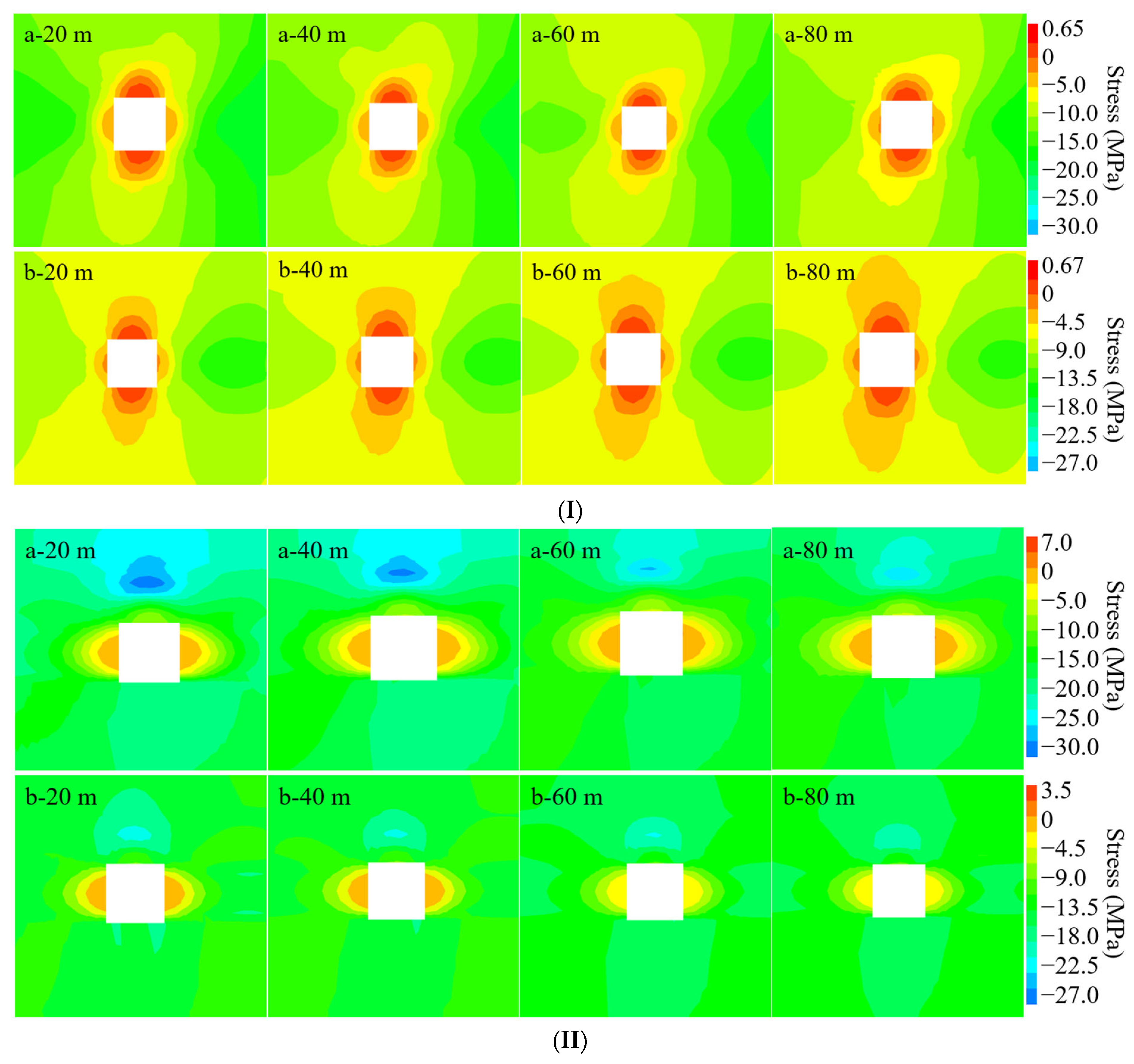
Figure 7 illustrates the cloud diagrams of stress fields in the roadway surrounding rock at various advancement distances for the two mining approaches. As the excavation face extends to 100 m, the surrounding rock shows distinct stress evolution behaviors in both vertical and lateral orientations. The vertical component of stress forms a concentric, semi-elliptical pattern spreading outward from the roadway, with pronounced intensities on both flanks compared to the roof and floor. Similarly, the lateral stress demonstrates a semi-elliptical distribution, where its peak values are also located near the roof and floor zones. In the bottom strata, lateral stress spans a wider area, whereas its intensity along the sidewalls is reduced and confined to a narrower band. While both mining strategies exhibit comparable distribution tendencies, the overall magnitudes of vertical and lateral stress within the roadway environment are notably diminished in the strip filling mining scenario compared to the conventional method, thereby helping to mitigate impact hazard.
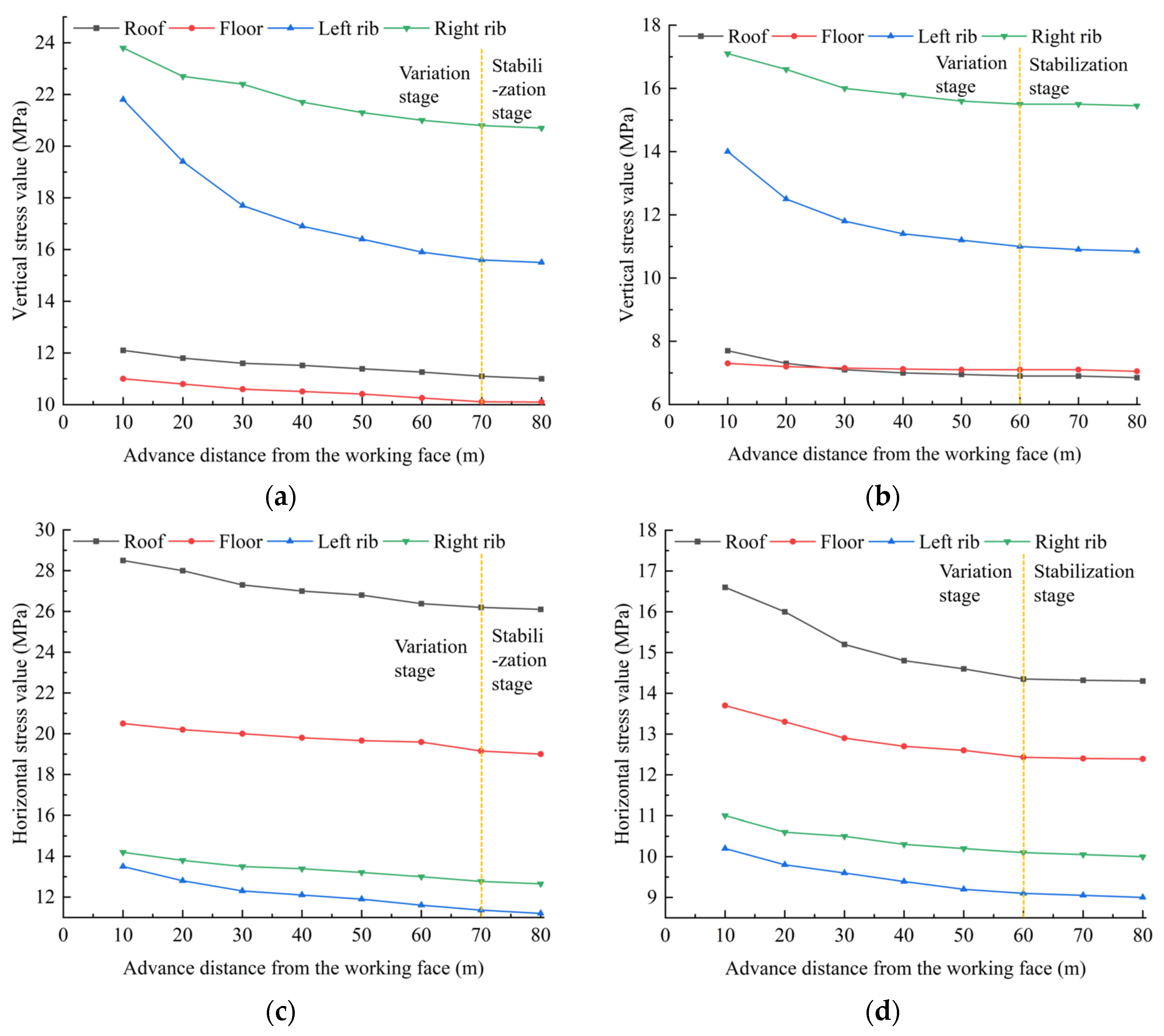
Figure 8 depicts the variation curves of stress within the surrounding rock of the roadway at varying excavation depths for both mining techniques. As excavation progresses, the stress field in the surrounding rock demonstrates a clearly defined spatial pattern. Specifically, the vertical component of stress tends to accumulate near the roadway’s sidewalls, whereas the horizontal stress primarily localizes around the roof and floor. With increased face advancement, both stress components exhibit a general decline. Furthermore, for the conventional mining approach, stress levels tend to stabilize once the face has progressed approximately 70 m. In contrast, under strip filling conditions, stabilization occurs earlier, at around 60 m. Stabilization was identified when the rate of change in stress or displacement values became negligible with further advancement of the working face. This assessment was based on monitoring the stress and displacement curves, which showed that beyond these critical distances (70 m for conventional and 60 m for strip filling mining), the values plateaued, indicating that the mining-induced influence had reached a steady state. These findings suggest that, relative to the traditional method, the strip filling approach offers improved conditions for ensuring roadway integrity and mitigating impact-related hazards during underground operations.
- (2)
Displacement variation characteristics of roadway surrounding rock
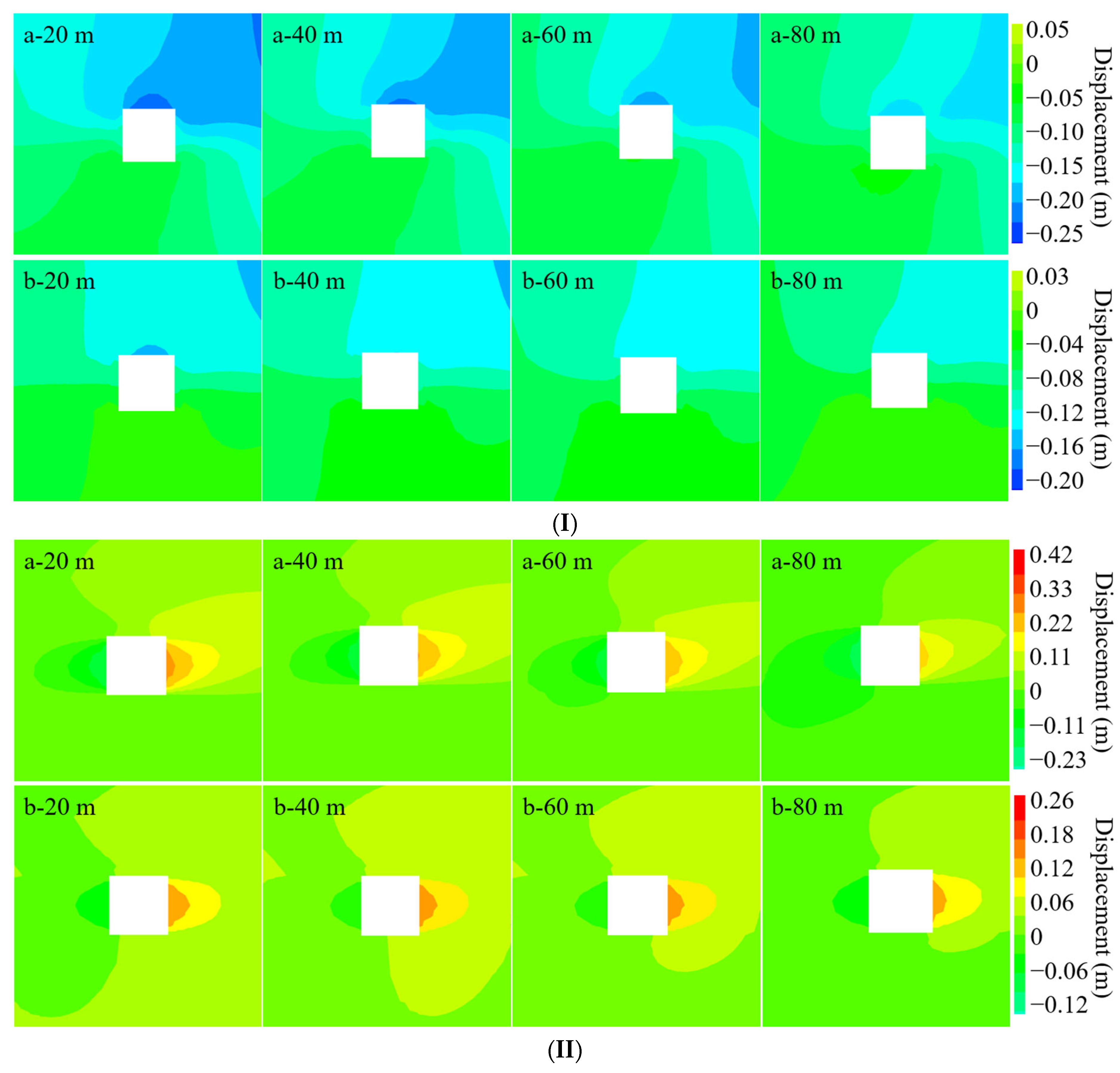
Figure 9 displays the cloud diagrams illustrating the deformation patterns of the surrounding strata near the roadway at various excavation depths. As indicated, the observed displacements are primarily concentrated in the roof, floor, and sidewalls. Vertically, the deformation is mainly distributed along the roof and floor, forming an outward-expanding semi-elliptical configuration centered around the roadway rock mass. With increasing excavation length, the vertical deformation exhibits a clear and regular evolution. Within the 0–40 m range, the peak vertical movement at the roof decreases, and between 40 m and 80 m, it gradually stabilizes.
Laterally, the deformation is most evident near the left and right walls of the roadway, showing a semi-butterfly pattern that expands outward, with the most notable displacement shift occurring approximately 20 m ahead of the excavation face. As mining continues, the horizontal deformation pattern adjusts, and the overall displacement magnitude continues to decline. On the whole, compared to the conventional mining method, strip filling mining significantly reduces deformation levels and offers superior support to the roof and sidewalls, thus enhancing the structural stability of the roadway system.
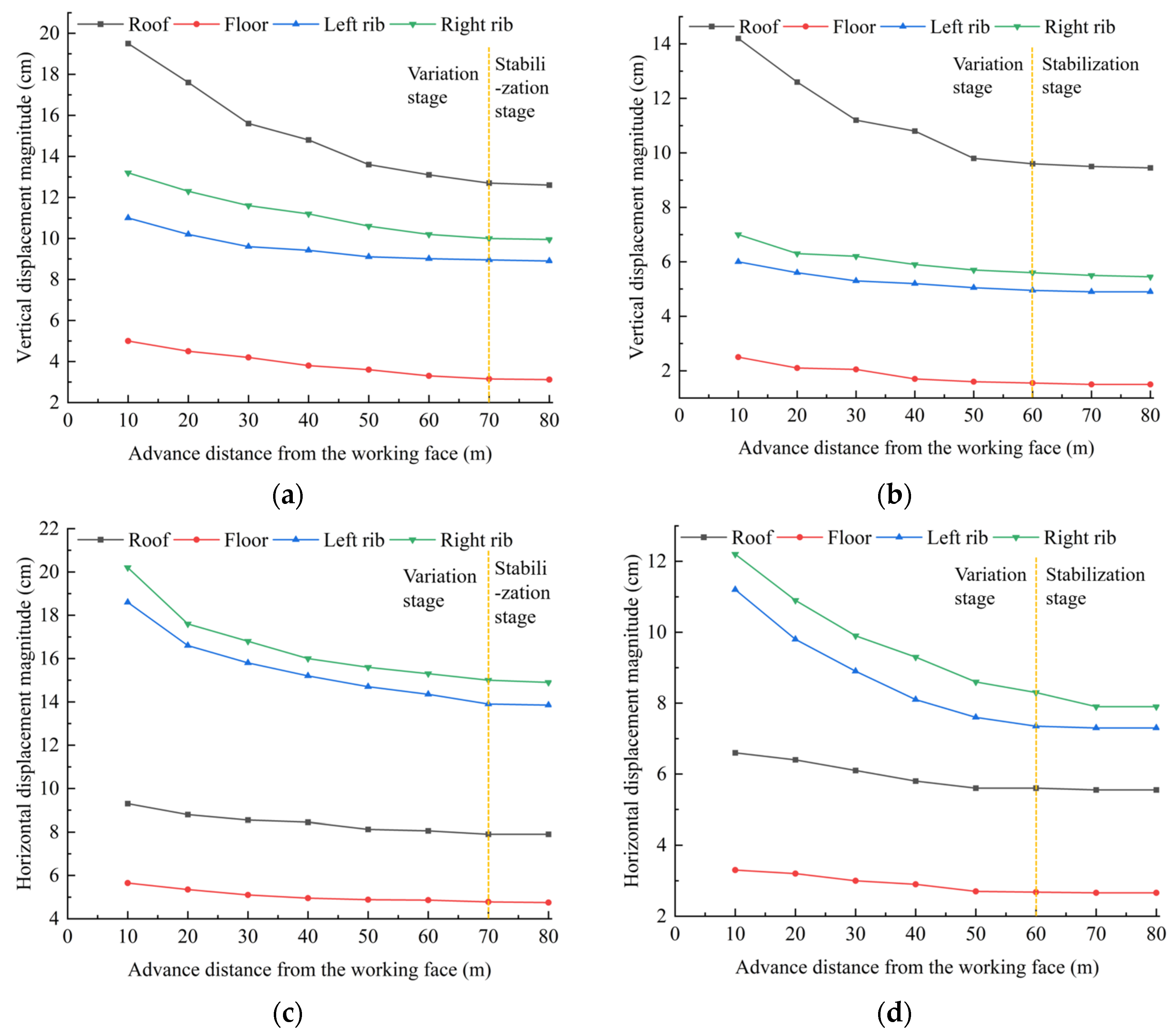
Figure 10 illustrates the deformation curves of the surrounding strata near the roadway at various excavation lengths. As indicated in the Figure, mining-induced disturbances cause noticeable deformation around the retreat roadway, with prominent vertical displacement occurring at the roof and horizontal displacement concentrated near the right wall. As the excavation depth increases, both vertical and lateral displacements exhibit a declining trend. The peak vertical deformation is found at the roof, whereas the highest lateral displacement variation is observed at the right sidewall. Furthermore, after a certain advance distance, both vertical and horizontal displacements tend to stabilize. Specifically, the influence range of mining-induced displacement changes in the retreat roadway under the original mining method is approximately 70 m, while that under the strip filling mining method is approximately 60 m. The adoption of strip filling mining not only improves resource recovery but also enhances roadway stability and reduces the impact hazard during underground mining operations.
- (3)
Development characteristics of plastic zones in roadway surrounding rock
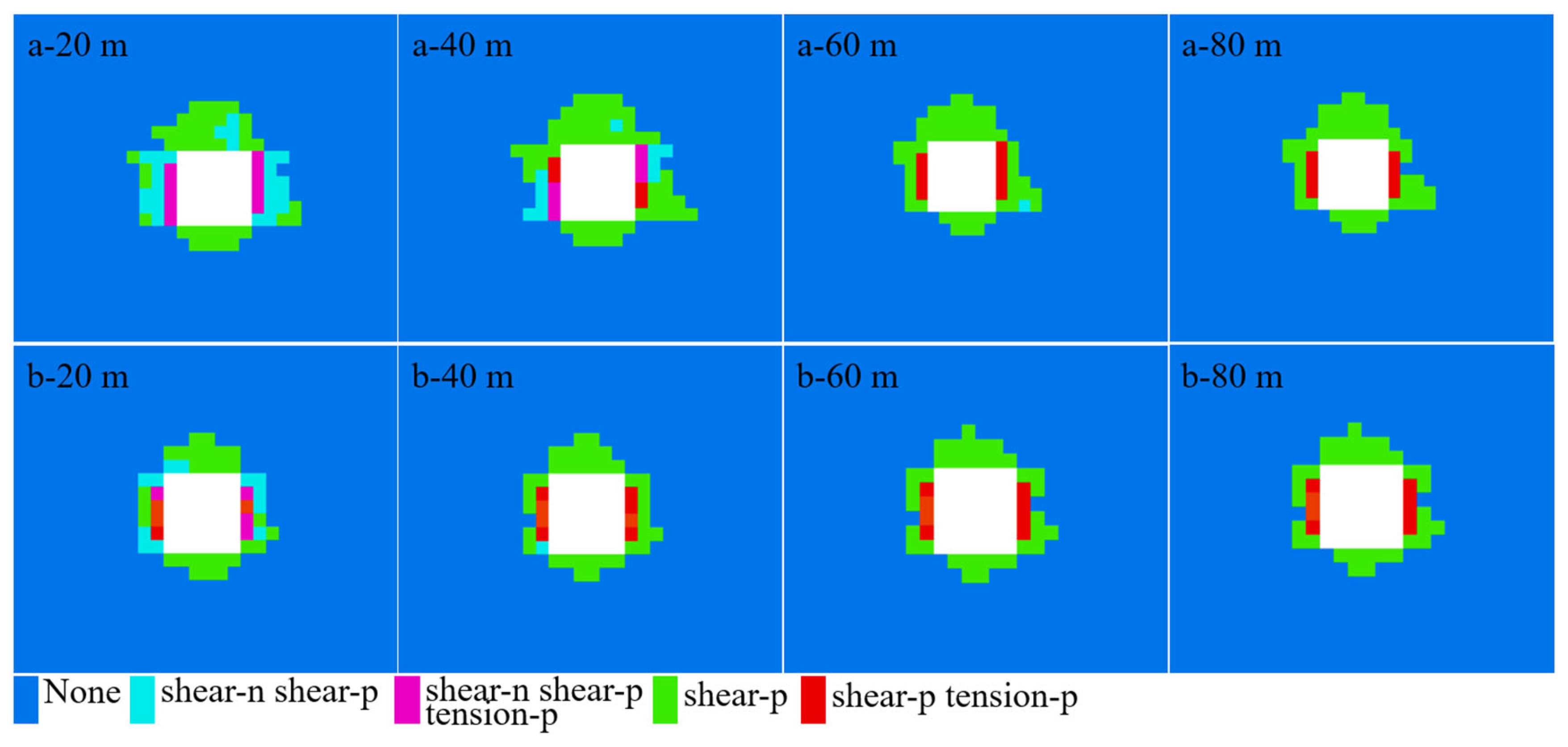
Figure 11 illustrates the cloud diagrams representing the spatial distribution of plastic zones surrounding the roadway under varying excavation lengths. As shown, the plastic zone exhibit an asymmetric layout, with concentrations primarily located at the roof as well as the left and right sidewalls. The most extensive plastic region is observed at the roof, followed by the sidewalls, where the right side displays a slightly broader range than the left. The floor exhibits the smallest plastic zone range. Overall, the plastic zone distribution around the roadway presents a characteristic of being larger at the top and smaller at the bottom, and smaller on the left and larger on the right.
The spatial distribution pattern of plastic zones exhibits substantial variation as the working face advances. When the excavation reaches approximately 20 m, the plastic deformation zone expands to its largest extent and is highly susceptible to mining-induced disturbances. As the face progresses into the range of 20–60 m, the plastic region becomes more confined, showing a tendency to cluster around the sidewalls. With continued advancement of the working face toward the interval of 60–80 m, the plastic zone contracts further, with deformation predominantly localized in the roof strata. Beyond this range, both the geometric configuration and extent of the plastic zones remain relatively stable, with minimal observable variation.
Overall, implementing strip filling mining not only significantly mitigates impact hazards but also enhances the protection of the retreat roadway. Furthermore, through the classification of plastic zone types, it is evident that the roadway’s surrounding rock predominantly undergoes shear-type failure under mining-induced stress conditions.
4.4. Comparative Analysis of Impact Hazard
Based on the preceding numerical simulation analysis, it can be concluded that, relative to the conventional mining method, strip filling mining is associated with a generally lower level of advance abutment pressure. This reduction effectively mitigates stress accumulation caused by mining-induced disturbances, particularly those impacting the retreat roadway. Further evaluation of stress response patterns reveals that both mining strategies display consistent behaviors in terms of vertical and horizontal stress evolution, displacement profiles, and plastic zone propagation. As the excavation progresses, these parameters—including stress intensity, deformation extent, and plastic zone dimensions—tend to gradually diminish for both methods.
A direct comparison of the key impact hazard indicators between the two mining methods is summarized as follows:
Peak Abutment Pressure: Consistently lower in strip filling mining, with a maximum reduction of 17.8%.
Roadway Stress: Both vertical and horizontal stresses in the surrounding rock were notably diminished under strip filling mining, contributing to a more stable roadway environment.
Roadway Deformation: Significant reduction in displacement levels was achieved, with the influence range of mining-induced displacement decreasing from ~70 m to ~60 m.
Plastic Zone: The extent of plastic zone development was effectively constrained, indicating enhanced surrounding rock integrity and a lower risk of failure.
Despite these shared tendencies, strip filling mining exhibits more pronounced reductions across all impact-related indicators. Compared with the conventional approach, it yields substantial declines in stress magnitude, displacement amplitude, and the scope of plastic zone development. Drawing on the “three-factor” theory—especially the energy source mechanism—and the framework of strength degradation and impact hazard suppression, minimizing stress concentration levels, displacement ranges, and the scale of rock mass failure plays a crucial role in reducing impact hazards and reinforcing overall mine stability. Therefore, implementing strip filling mining not only promotes better resource recovery but also enhances the safety of underground operations. It provides robust theoretical and technical support for effective impact control and safe mine management under complex geological conditions.
5. Engineering and Economic Cost Analysis
The implementation of strip filling mining has been shown to substantially improve coal resource recovery efficiency while concurrently mitigating the occurrence probability of rockburst events. Nevertheless, the necessity of conducting underground backfilling inevitably incurs additional economic expenditures. Therefore, it becomes essential to carry out a thorough assessment of the technical and economic viability of applying strip filling mining techniques.
A promising avenue for further cost optimization involves the utilization of on-site geological materials. As described in the engineering overview, the immediate roof and floor of the coal seam primarily consist of fine sandstone, which is relatively friable and can be easily disaggregated. This readily available country rock presents a viable potential source for backfilling material. Incorporating a proportion of this excavated rock into the backfill mix could significantly reduce the dependence on externally sourced materials, such as the coal gangue considered in the cost analysis (
Table 2). This strategy would not only lower direct material and transportation costs but also align with sustainable mining practices by enhancing the comprehensive utilization of mining waste.
According to the evaluation results in
Table 2, the economic returns from coal pillar recovery significantly outweigh the associated filling costs. The potential integration of locally available disaggregated rock into the backfill mixture, as discussed, could further improve this favorable economic balance. Thus, the implementation of strip filling mining is economically justified.
6. Discussion
The strip filling mining method in upward mining faces proposed in this study has been theoretically proven to effectively reduce stress concentration, suppress the expansion of plastic zones, and maintain roadway stability, thereby lowering the impact hazard. However, the current research relies solely on field investigation, theoretical analysis, and numerical simulation, without long-term validation in practical engineering scenarios. Consequently, the reliability and generalizability of the findings in real-world applications remain to be further verified. Despite this limitation, the study offers a new perspective for related research. The proposed theoretical analysis framework and numerical simulation approach can serve as a valuable reference for evaluating impact hazards, optimizing mining designs, and developing safety measures in mines with similar geological conditions. Future work should integrate practical engineering data to refine the theoretical system and accelerate the engineering application of the research findings.
7. Conclusions
This study investigated the impact hazard control mechanism of strip filling mining in upward mining faces through an integrated approach of theoretical analysis and numerical modeling (FLAC3D). The primary objective was to assess the effectiveness of this method in mitigating rockburst hazards compared to the conventional mining method. The key findings, which confirm that the research objectives have been successfully met, are summarized as follows:
In this stage, the mining process is characterized by filling mining with a high filling rate. The roof does not experience collapse, with only a few minor cracks and slight separations observed. The displacement magnitude and stress concentration are relatively low, resulting in a low impact hazard.
- (2)
Second stage:
- ①
The evolution of advance abutment pressure under strip filling mining follows a pattern similar to that under the traditional mining method, featuring a sharp increase at first, followed by a gradual decline and eventual stabilization. Nevertheless, at all excavation depths, the stress magnitudes in strip filling mining are consistently lower than those in the conventional approach, with a peak reduction reaching 17.8%.
- ②
For both mining schemes, vertical and horizontal stress in the surrounding rock increases with advancing excavation. Stress accumulation is more severe near the sidewalls than at the roof and floor. Notably, the horizontal stress peaks at the roof and floor and subsequently declines as the working face progresses. Strip filling mining effectively lowers the intensity of both stress components, thereby minimizing the likelihood of impact-related events.
- ③
As the working face advances, both vertical and lateral displacements of the surrounding rock show a downward trend. The strip filling approach proves effective in managing deformation, enhancing structural stability, reducing the likelihood of rockburst events, and promoting safer mining conditions.
- ④
Strip filling mining also plays a crucial role in constraining the spread of the plastic zone. Compared to the original method, it results in a smaller deformation zone and greater surrounding rock stability, thus contributing to reduced impact hazard and improved roadway safety during mining.
