Article

Strong Mining Pressure Control in a Deep High-Gas Coal Seam with a Hard Roof Using Hydraulic Fracturing Technology

1
School of Mines, China University of Mining and Technology, Xuzhou 221116, China
2
China Institute of Coal Science, Beijing 100013, China
*
Author to whom correspondence should be addressed.
Appl. Sci. 2025, 15(20), 10940; https://doi.org/10.3390/app152010940 (registering DOI)
Submission received: 16 August 2025 / Revised: 9 October 2025 / Accepted: 9 October 2025 / Published: 11 October 2025

Abstract

The prevention and control of coupled disasters caused by strong mining pressure and high gas is currently the main challenge during coal seam deep mining in the southeastern mining areas of Shanxi Province. This paper takes the 1310 working face of Hudi Coal Mine as the engineering background, analyzing its on-site strong mining pressure event and triggering factors. A reasonable hydraulic fracturing scheme (including layer selection, drilling parameter design, etc.) is proposed based on theoretical analysis of the principles and advantages of hydraulic fracturing technology. Then, the physical analog modeling (PAM) method was used to study the movement law and fracture development of the overlying strata during coal seam mining after hydraulic fracturing. The weakening effect of mining pressure was analyzed through the evolution law of roof stress. The deformation of the surrounding rock in the roadway, coal drilling cuttings, support working resistance, and roof fracture development of the in situ measurement results show that hydraulic fracturing has a good effect on weakening mining pressure. It has achieved safe and efficient mining of coal seams while providing a reference for coal mines with similar conditions.

1. Introduction

As an important energy base in China, Shanxi Province’s coal production accounts for more than a quarter of the country’s total coal production. The country has introduced a series of sustainable development policies for the coal industry in Shanxi Province. Its coal resources generally exhibit typical characteristics of hard roof rock layers and high gas content [1]. The coal seam roof of the main mining areas in the province (such as Datong, Jincheng, etc.) is mostly thick sandstone or conglomerate, with a uniaxial compressive strength generally exceeding 50 MPa, exhibiting significant integrity and strong bearing characteristics [2]. In recent years, with the gradual depletion of shallow coal resources, the proportion of mines buried deeper than 600 m has exceeded 40%. During this process, coupling strong mining pressure and high gas caused by breaking the hard roof significantly increases the difficulty of disaster prevention and control. The main disaster mechanism is that the hard roof is suspended in large areas, and the accumulated elastic energy is instantly released, causing strong mining pressure and exacerbating abnormal gas outbursts [3,4,5].
Related scholars have researched the fracture of hard roofs in deep coal seams [6,7] and the prevention and control of gas disasters [8], and have achieved certain research results. Bu et al. [9] analyzed the application of hydraulic fracturing technology to eliminate overloading conditions of hydraulic supports, and proposed engineering countermeasures for implementing strong dynamic pressure control on hard roof strata. Zhang et al. [10] established mechanical models for the instability of composite coal seam under hard roof conditions during mining, revealing the mechanisms of rock burst. Ma et al. [11] calculated the maximum principal compressive stress for fracture opening under bidirectional stress conditions in coal-rock masses, elucidating the propagation mechanism of hydraulic fractures in hard roof strata. Zhang et al. [12] analyzed the effects of stress concentration coefficient, lateral coefficient, in situ stress, and perforation angle on fracture propagation. Dou et al. [13] conducted physical analog experiments of coal seam mining under hard roof conditions and revealed the influence of hard roof fracture on stress evolution. Huang et al. [14] implemented hydraulic fracturing in measurement roadways based on the propagation laws of hydraulic fractures and gas emission mechanisms.
In addition, some scholars have focused on geo-mechanical risk assessment, stress–strain modeling, and deep mining safety in weak and gas-dynamically active rock masses and obtained beneficial results [15,16]. However, most existing theories and technological achievements are based on single-disaster analysis, which cannot meet the engineering requirements of strong mining pressure and high gas-disaster coupling effects. There is a lack of research on selecting hydraulic fracturing layers, drilling parameter design, and fracturing effects in the deep mining areas of Shanxi Province, China.
Focusing on the difficult problem of strong ground pressure disasters in deep high gas coal seams under the condition of composite hard roofs at Hudi Coal Mine, Jincheng City, China, the on-site strong mining pressure event and its triggering factors were analyzed. A reasonable hydraulic fracturing scheme (including layer selection, drilling parameter design, etc.) is proposed based on theoretical analysis of hydraulic fracturing technology. Then, the movement law, fracture development of the overlying strata, and weakening effect of mining pressure after hydraulic fracturing were analyzed. The in situ measurement results show that the control effect of related indicators, such as deformation of the surrounding rock in the roadway, coal drilling cuttings, support working resistance, and roof fracture development in hydraulic fracturing, was good. The research results can provide technical guidance for the safe and efficient mining of coal mines with similar conditions in Shanxi. Based on governmental directives and programs, the research drives the sustainable development, industry, and economic growth of local mining areas.

2. Research Background

2.1. Working Face Overview

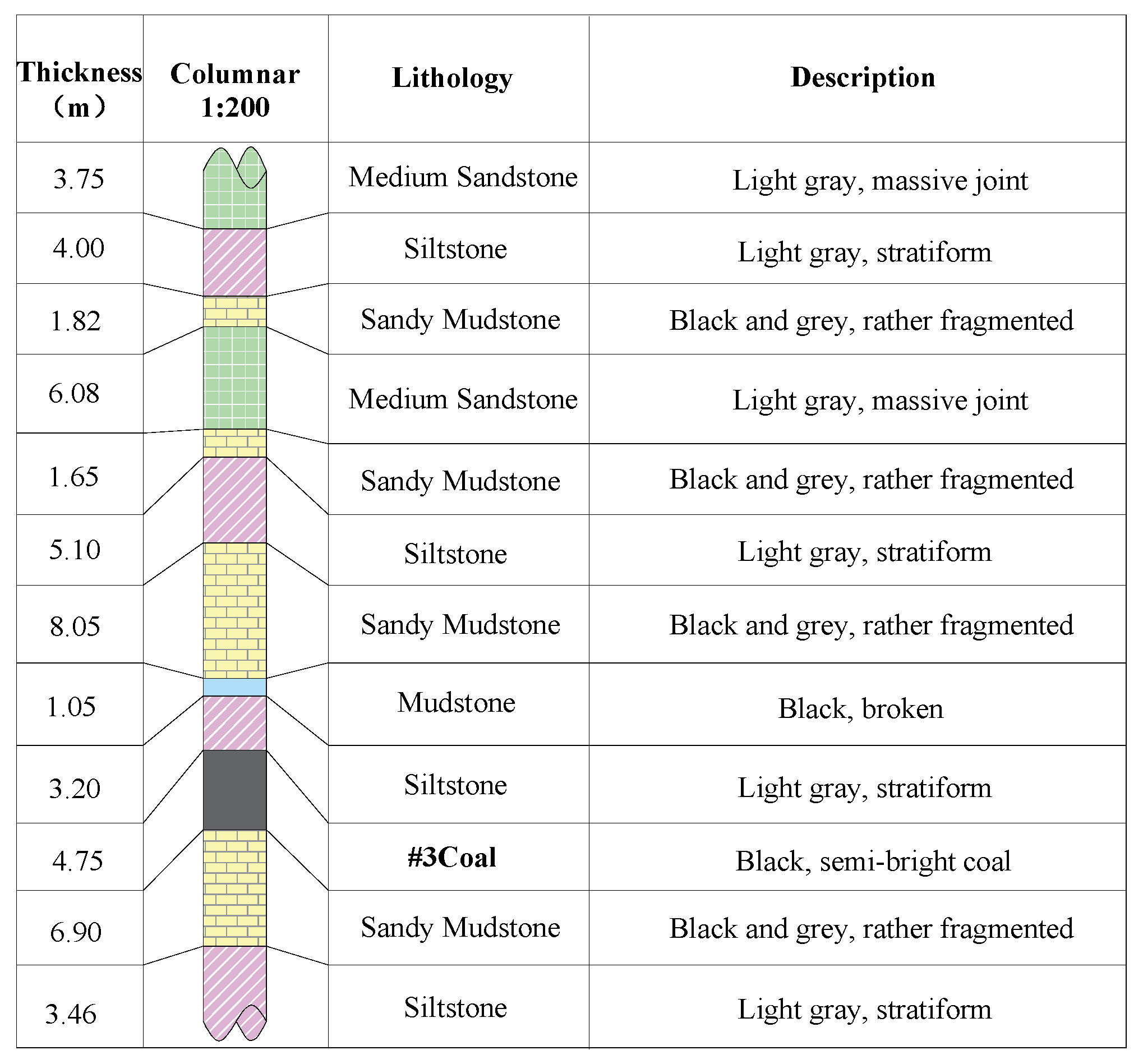
The 1310 working face is located in the first area of Hudi Coal Mine, Jincheng City, China, mainly mining the 3 # coal seam. The coal seam thickness is 4.60~5.00 m, with an average thickness of 4.75 m. The coal seam dip angle is 0~8°, with an average of 5°. The coal seam structure is simple, but the coal seam gas content is relatively high, before coal seam mining, it is necessary to arrange bottom drainage tunnels for pre-extraction of gas, The surface elevation of the working face is +1012.4 to +1193.2 m, the coal seam floor elevation is +340 to +456 m, the length of the working face is 219.7 m, and the strike length of the working face is 2563.9 m. The south side is the goaf of the 1309 working face, which has been fully mined; The north side is the 1311 working face, and mining has not yet begun. As of now, the 1310 working face has progressed 2350 m. The coal seam roof mainly comprises sandy mudstone, fine-grained sandstone, and medium sandstone. Among them, the top is siltstone, the basic top is sandy mudstone, and the bottom is sandy mudstone. The compressive strength of mudstone roof rocks is generally greater than 40 MPa, and the compressive strength of sandstone roof rocks is generally greater than 60 MPa. The other geological and hydrological conditions of the mine are simple. During the mining period of the working face, the main problem is preventing and controlling dynamic disasters under the coupling of gas and strong mining pressure. The layout plan of the 1310 working face roadway and the regional comprehensive lithological column are shown in Figure 1 and Figure 2.

2.2. Analysis of Strong Mining Pressure Events and Inducing Factors

During the mining period of the 1310 working face, two strong mining pressure events occurred in the 1310 transportation roadway. One occurred within a range of about 150 m from the 4 # connecting roadway to the 1310 working face, resulting in severe deformation of the roadway and a cross-sectional shrinkage area of over 50%; The single prop underwent three different degrees of deformation, with severe deformation of the top-plate steel strip, reaching a deformation degree of over 60%; Secondly, pressure-relief drilling was carried out at a distance of 50 m from the 3 # connecting roadway. The drilling rig was damaged at a distance of 10.5 m during construction. During the withdrawal of the drill rod, a coal cannon phenomenon occurred in the construction area, and the energy accumulated in the coal body was instantly released with a loud noise. Subsequently, the pressure-relief drilling rod was ejected, and significant deformation occurred on the coal pillar side of the 1310 transportation roadway (Figure 3).
The manifestation of strong mining pressure results from the superposition of geological structures and mining disturbances. The two strong mining pressure events mentioned above have affected the efficiency and safety of the mining face to varying degrees. The main influencing factors include roof features, mining speed, mining depth and gas. During the mining period of the working face, the overlying roof is generally hard. After the initial and periodic fractures, the roof forms a hinged structure and a hanging roof, resulting in strong mining pressure. At the same time, it is affected by the lateral hanging roof of the adjacent 1308 goaf, and the collapsed rock layers are insufficient to fill the goaf and support the overlying roof, causing coal pillar compression and increasing the internal stress of the coal pillar. Under the influence of disturbance factors, the roof moves or collapses, accumulating energy release, and easily causing mining pressure to appear. In the week before the occurrence of the mining pressure event, the advancing speed of the working face fluctuated from 2.2 m/d to 9.5 m/d, accompanied by a synchronous increase in the maximum single-day micro seismic energy from 2.75 × 10⁴ J to 4.82 × 10⁴ J, with an increase of 75%. This indicates that with the continuous increase in mining speed, the degree of roof activity is becoming more and more intense. Based on the experience of mine microseismic data, the significant fluctuations in the pushing speed of the working face lead to irregular forward movement of the pre-peak stress of the working face, which destroys the original stress conduction mode of the coal seam and causes local stress concentration in the coal seam. When the coal seam load is exceeded, a large amount of elastic energy is released due to local damage, forming high-energy microseismic events or inducing mining pressure events. At the same time, the discreteness of the pushing speed of the working face disrupts the regular activity of the overlying roof rock layer, causing uncontrollable movement of the roof near the coal seam. During the stage of drastic changes in pushing speed, the damage or fracture of the hard roof induces the manifestation of mining pressure. The average mining depth of the 1310 working face exceeds 700 m. According to the measured data of the original rock stress field of the coal seam in the mine field, it is known that the original rock stress of the coal seam is greatly affected by the burial depth. The initial vertical stress distribution range of the 3 # coal seam is between 8.0 and 19.50 MPa, and the stress gradient change is small. According to the actual situation, the excavation of the already mined working face was carried out, and the vertical stress distribution of coal # 3 after mining was found to be between 10.0 and 66.1 MPa. Due to the large mining depth, the initial vertical stress of the coal seam in the 1310 working face is relatively high. The vertical stress of the coal seam further increases due to the impact of mining, especially within the range of advanced stress. The stress concentration coefficient in some areas exceeds 3.0, which poses a certain risk of strong mining pressure. Considering that the mine is a high gas mine, a coal pillar width of 24 m was left between the 1310 and 1308 working faces. The width of the coal pillar was unreasonable, and the gas inside the coal pillar was not extracted, resulting in a defect in gas control. This led to areas with high gas pressure inside the coal pillar. The construction of pressure-relief holes provided a channel for the rapid emission of gas, and the vibration of the coal cannon accelerated the desorption of adsorbed gas, causing the gas to push the drill rod out.

3. Strong Mining Pressure Control Technology for Deep, High-Gas Coal Seams

3.1. Principles of Hydraulic Fracturing Technology

Three types of active weakening techniques are mainly used in engineering practice to address the strong mining pressure induced by hard roof plates in deep mining: blasting-induced fracturing, hydraulic softening, and directional fracturing [17]. Among them, deep hole blasting pre-splitting requires encapsulating explosives in the roof, which makes the blasting operation difficult, costly, and difficult to effectively control the pre-splitting effect on the roof, especially for high gas coal seam conditions, threatening the safety production of the working face [18]. The water injection weakening technology has certain requirements for the properties of the rock mass, and laboratory tests need to be conducted in advance to fully grasp the softening characteristics of the rock mass when encountering water, which has significant limitations [19]. Compared to conventional hydraulic fracturing, directional hydraulic fracturing forms a controllable fracture network in the roof through high-pressure water flow, which combines high construction efficiency and precise weakening, and has advantages such as safety, no pollution, low economic cost, and significant weakening effect [20,21].
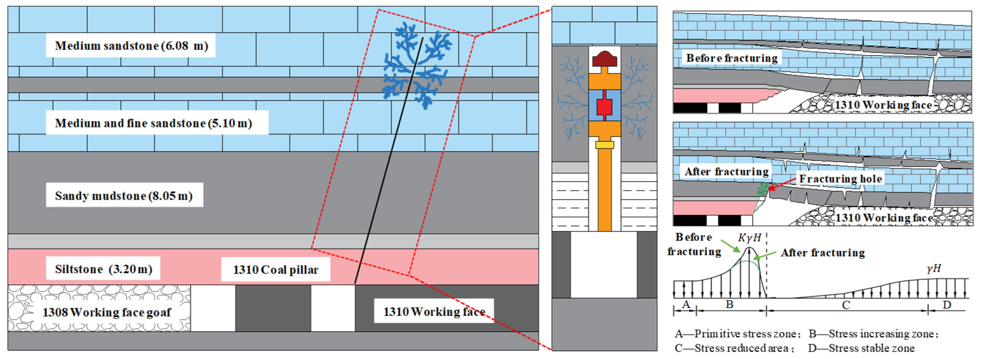
The core of hydraulic fracturing and pressure relief for directional long boreholes on the roadway roof is to prevent instability and damage to the roadway and coal pillars during a single mining operation, as well as to prevent large deformation and damage under the advanced support pressure of the working face when they are reused. Therefore, it is necessary to perform hydraulic fracturing on the difficult to collapse roof affected by the rock collapse angle before the mining of the working face, to destroy the integrity of the roof rock above the collapse angle, thereby increasing the collapse angle of the working face, reducing the lateral overhanging area of the working face [22], reducing the stress concentration near the coal pillar, weakening the peak of the advance and lateral residual support pressure, and ultimately achieving the goal of placing the roadway and coal pillar in a lower stress zone [23]. The schematic diagram of the roof structure before and after fracturing, and the stress distribution of the working face towards the roof are shown in Figure 4.

3.2. Hydraulic Fracturing Scheme Design

3.2.1. Layer Selection

According to the actual parameters on site, the coal thickness is 4.85 m, the recovery rate is 93%, and the lithology and fragmentation coefficient of each layer’s roof are calculated based on the bar chart. Table 1 concludes that the residual coal seam needs to collapse upwards until the sandstone above the roof meets the requirements for filling the mining space. Currently, the cumulative fragmentation height is 6.21 m, exceeding the 4.51 m of fracture space generated after coal seam mining.
Based on the above theoretical analysis, the effective filling of the goaf in the 1310 working face requires ensuring that all the overlying rock layers within a range of 25.13 m participate in the breaking movement to fill the goaf. To eliminate the risk of disaster caused by the hanging roof above the transportation roadway, a targeted “dual key layer” fracturing control system was designed: directional fracturing was carried out on 8.05 m sandy mudstone (key weak layer) and 6.28 m medium sandstone (key bearing layer). This design fully considers the differences in rock mechanics characteristics, establishes initial failure channels using the relatively weak sandy mudstone, and then performs medium sandstone fracturing to achieve controllable fracture of the roof structure. After the implementation of the project, ensure that the top plate of the triangular area at the end of the working face collapses synchronously with the progress of the mining area.

3.2.2. Drilling Parameter

The hydraulic fracturing project adopts a ZQJC-1000/11.0S column-type pneumatic drilling rig, Jincheng City, China, and precise drilling construction is carried out in the 1310 transport roadway. The fracturing hole diameter is 46~48 mm, and the control hole diameter is 42 mm. Fracturing holes are arranged at intervals of 20 m along the direction of the roadway, with openings located near the production roof (1 m away from the roadway). The shallow hole section is 8.6 m deep, and the deep hole section is 22.9 m deep, with an elevation angle of 75° ± 2° and a uniform azimuth angle of 180° (perpendicular to the coal wall). A total of 9 sets of fracturing boreholes are arranged to form a stress intervention field. Adopting a backward segmented fracturing process, combined with a double capsule sealer, Jincheng City, China, to achieve precise fracturing of the sandy mudstone and medium sandstone dual target layers. By adjusting the water injection pressure gradient to control the crack propagation morphology, the sandy mudstone layer focuses on forming a network of microcracks. In contrast, the medium sandstone layer targets macroscopic formation through cracks.
Establish a monitoring system for parameters such as drilling water flow rate, anchor cable water seepage rate, and micro seismic monitoring, and optimize fracturing parameters in real time based on on-site observation data. Figure 5 shows the hydraulic fracturing scheme design, equipment, and on-site construction.

4. Mining Pressure Weakening Effect Simulation Experiment of Hydraulic Fracturing

4.1. Experimental Scheme Design

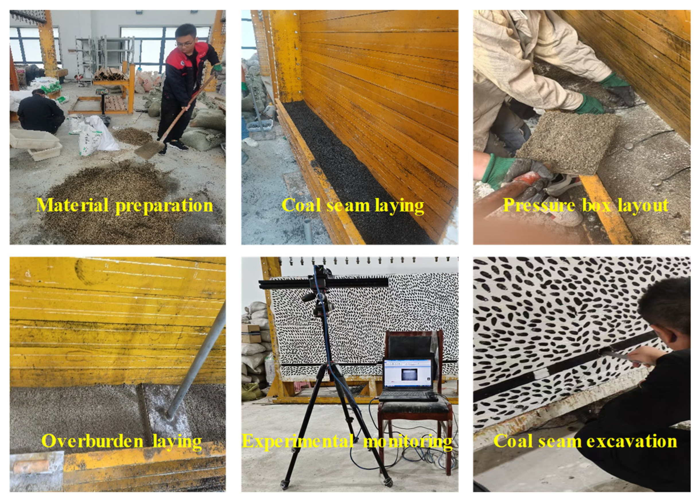
This paper mainly analyzes the impact of the mining process after roof cutting on the retention effect, roadway deformation, roof structure evolution, and overlying rock movement law of the 1310 transport roadway by constructing a physical analog experiment of roof cutting and pressure relief in the 1310 working face. Based on the theory of physical analog material (PAM) simulation and similarity criteria [24], the geometric similarity ratio of the model is determined to be 1:150, and the stress similarity ratio is 1:225. The experimental model has a length of 250 cm, a thickness of 30 cm, and a height of 125.7 cm. A compensating load of 0.47 MPa is applied to the upper part of the model. Selecting sand as aggregate, gypsum and calcium carbonate as bonding materials, water as a mixture, and mica powder as layered material for PAMs. The simulated working face advances 0.6 m per cycle, with six cycles per day and 12 coal cuts per day, resulting in a daily advance of 7.2 m. Therefore, each excavation is 4.8 cm, with an interval of 5 min. The PAM modeling of the laying and excavation process is shown in Figure 6.
This experiment simulates a top cutting length of 153 mm and an angle of 75°. A total of 15 pressure sensors are installed in the simulation. Measurement points 1-1 # and 1-2 # are arranged at the top of the coal pillar on the left side of the 1310 working face. Measurement points 1-3 #, 1-4 #, and 1-5 # are arranged at the top of the roadway on the left side of the 1310 working face. Measurement points 1-6 #, 1-7 #, 1-9 #, and 1-10 # are arranged in the sandy mudstone and medium sandstone layers on both sides of the top cutting. Measurement points 1-8 # and 1-11 #~1-15 # are laid in sequence from left to right above the 1310 working face in the direct top. The pressure sensors are spaced 200 mm apart. The Matchid-2D commercial software package 2.0 version is used. The contact-type full-field strain measurement system monitors the displacement of the overlying rock. The simplified model and monitoring layout scheme for the physical similarity simulation test of the movement characteristics of overlying rock and the stability of the surrounding rock in the 1310 working face during top cutting and pressure relief are shown in Figure 7. PAM parameters used to simulate the coal and rock strata mechanical properties are listed in Table 2.

4.2. Experimental Results

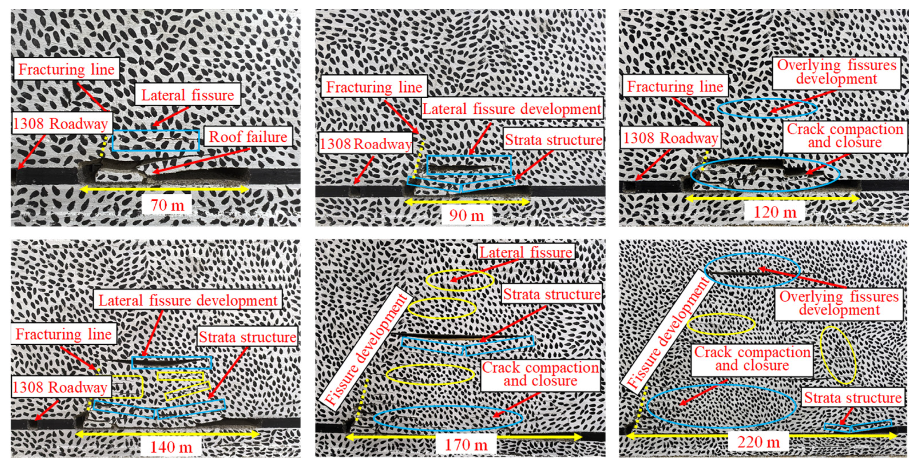
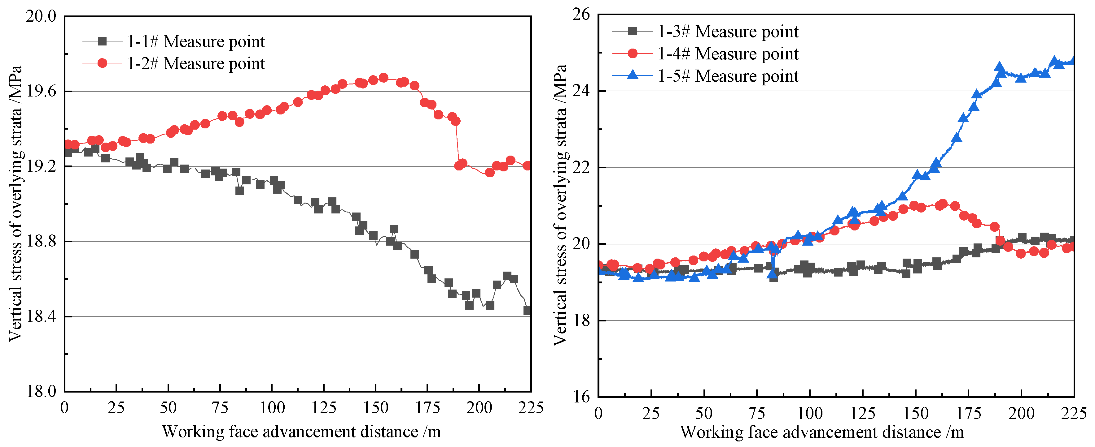
With the continuous mining of the working face, the overlying rock strata show an overall evolution characteristic of “crack development, obvious separation, crack expansion, rock fracture, and crack compaction and closure” under the influence of mining. When the advancing distance of the working face is 70 m, 90 m, 120 m, 140 m, 170 m, and 220 m, the characteristics of roof rock movement and crack evolution are shown in Figure 8. The stress distribution of adjacent tunnels and coal pillars caused by mining disturbance on the working face, as well as the stress change curves before and after roof cutting, are shown in Figure 9 and Figure 10.
From Figure 8, when the excavation reaches 70 m, the area of the goaf gradually expands, and the subsidence speed of the overlying rock layer accelerates. The subsidence range also extends to both sides of the roadway and working face, and the roof of the goaf behind gradually collapses. When the excavation reaches 90 m, the two deformations are not coordinated in the contact area between mudstone and siltstone, and the separation phenomenon intensifies. At the same time, the siltstone layer begins to show signs of fracture above the goaf, forming a larger rock block structure. When the excavation of the working face reaches 140 m, the goaf area is large enough, and the collapse and deformation of the overlying rock layers enter a relatively stable stage. The direct top rock layer collapses to the goaf, forming a collapse zone. The collapsed rock blocks pile up with each other, forming a compacted collapse zone in the goaf, providing certain support for the overlying rock layer. When the excavation of the working face reaches 220 m, the basic roof rock layer undergoes sufficient bending deformation and fracture, forming a large rock block structure that collapses above the goaf, and together with the collapsed direct roof gangue, forms the filling body of the goaf. Above the collapse zone, a fracture zone is formed, in which the fractures crisscross and have a large width, affecting the overall stability of the rock formation.
With the excavation of the working face, the stability of the top cutting cantilever beam further decreases. At the root of the cantilever beam, due to the continuous action of mining stress and rock fragmentation, its bearing capacity sharply decreases, resulting in partial collapse of the cantilever beam. Rock layer separation above the cantilever beam is more complex, forming a multi-layered separation structure. The relative slip between each layer of rock increases, and the roof structure becomes more unstable. The collapse of the rock layers above forms collapse zones and fracture zones. The accumulation of gangue in the collapse zone provides certain support for the overlying rock layers, gradually stabilizing the deformation and collapse of the rock layers. However, the stress adjustment inside the rock layers is still ongoing, and the morphology and stability of the collapse zone and fracture zone need to be continuously monitored to prevent roof accidents from occurring. Above the roadway, a complex roof structure composed of collapse zones, fracture zones, and curved subsidence zones has been formed. The stress adjustment inside the rock layers is still ongoing, and the accumulation of fragmented rock masses in the collapse zone supports the overlying rock layers, slowing down the subsidence speed of the overlying rock layers and ultimately reaching a relatively stable state.
From Figure 9 and Figure 10, it can be seen that measurement points 1-1 # and 1-2 # are in the boundary protection coal pillar and are mainly affected by two stages of mining. The first stage is the initial fracture stage. While advancing to 160 m in the working face, the key rock layer is before fracture, so the stress shows a slow increasing trend, with a peak stress of 19.7 MPa. The second stage is the pressure-relief stage, when the key hard rock breaks, it leads to pressure relief and a decreasing trend in stress, with the 1-2 # measuring points dropping to 18.4 MPa. Throughout the mining project, the stress at measuring points 1 and 2 was unaffected by the mining stage and showed no significant changes. The main reason is that it is less affected by mining activities, and the overall stress is close to the original rock stress.
The measuring points 1-3 #, 1-4 #, and 1-5 # are located above the roadway, and the trend of vertical stress changes in the overlying rock can be divided into three stages. The first stage is cutting and unloading the pressure layer, and the stress shows a slow increasing trend. When the working face advances about 90 m and reaches the fracture layer, the pressure is suddenly relieved, and the stress at measuring points 1-5 shows a decreasing trend. The second stage is the periodic fracture stage, where the roof experiences periodic fracture and subsidence, and the stress shows a continuously increasing trend, with a peak stress of 24.5 MPa and a stress concentration factor of 1.26. The third stage is the compaction and stabilization stage. When the working face advances 190 m, the rock strata in the goaf behind the working face collapse and compact, and there is no significant mining pressure activity on the roof. The stress at measuring points 1-3 and 1-4 is stable at around 20 MPa, and the stress at measuring points 1-5 is stable at 24.7 MPa. This differential change is mainly due to the different stress concentrations caused by mining effects.
The measuring points 1-5 #, 1-6 #, and 1-7 # are on the left side along the top cutting line. While advancing 90 m on the working face, they did not reach the top cutting pressure-relief stage, and the stress showed a slowly increasing trend. After advancing 120 m in the working face, the key top plate broke and the stress was released, showing a slight decrease of about 2 MPa. The top plate will produce a pressure lifting and rotation effect. After cutting the top, the left side will be subjected to a large force, so the stress shows a linear increase trend. The peak stress of measuring points 1-6 reached 31.1 MPa, and the stress concentration factor was 1.64. The measuring points 1-8 #, 1-9 #, and 1-10 # are on the right side along the cutting line. When the excavation of the working face begins, if the cutting line breaks at the cutting point, the roof will undergo a continuous pressure-relief process, resulting in a continuous decrease in stress. Among them, the stress at measuring points 1-8 # and 1-9 # stabilizes after dropping to 13 MPa, while the stress at measuring points 1-10 # stabilizes after dropping to 3 MPa. The stress change characteristics are directly related to the laws of roof movement structural adjustments (e.g., cantilever rotation, redistribution from concentrated to diffuse stress). The stress monitoring points on the left side of the fracturing line are generally located in the stress concentration area of the roof, while the right side is within the pressure-relief range of coal seam mining.

5. Engineering Application Analysis

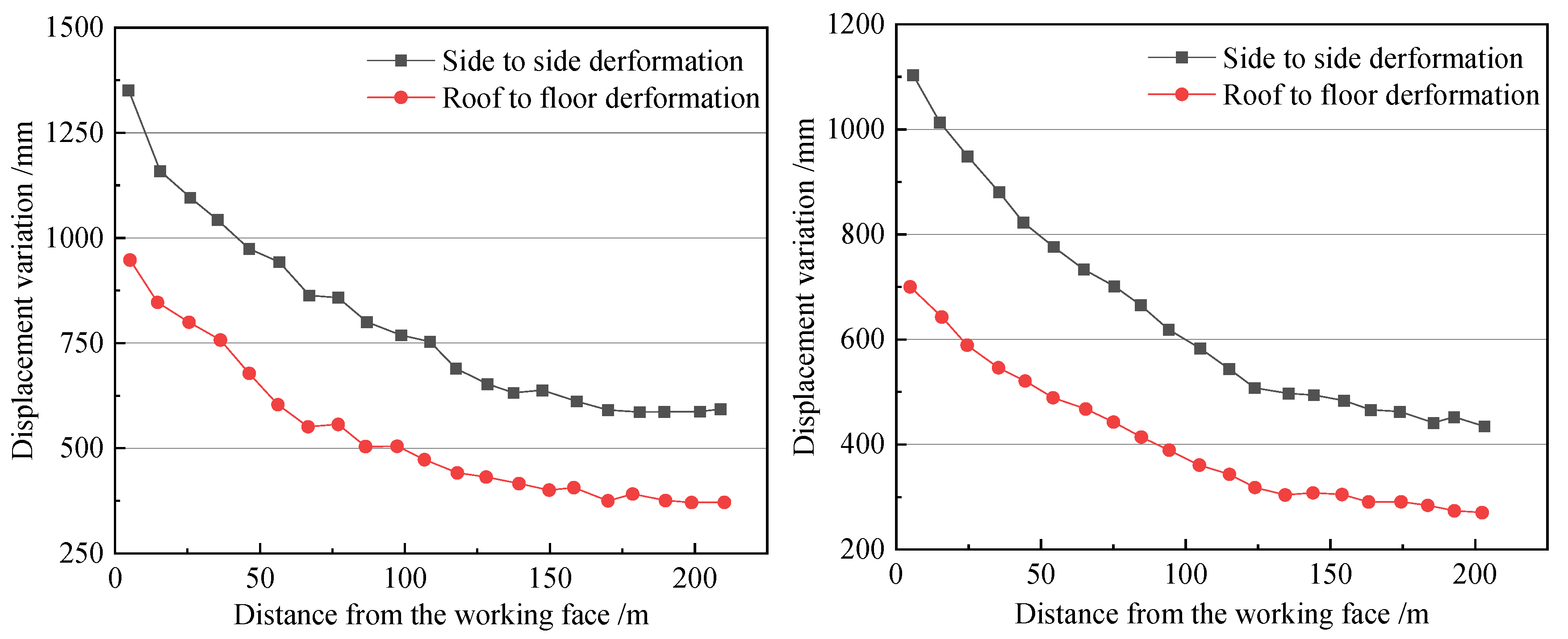
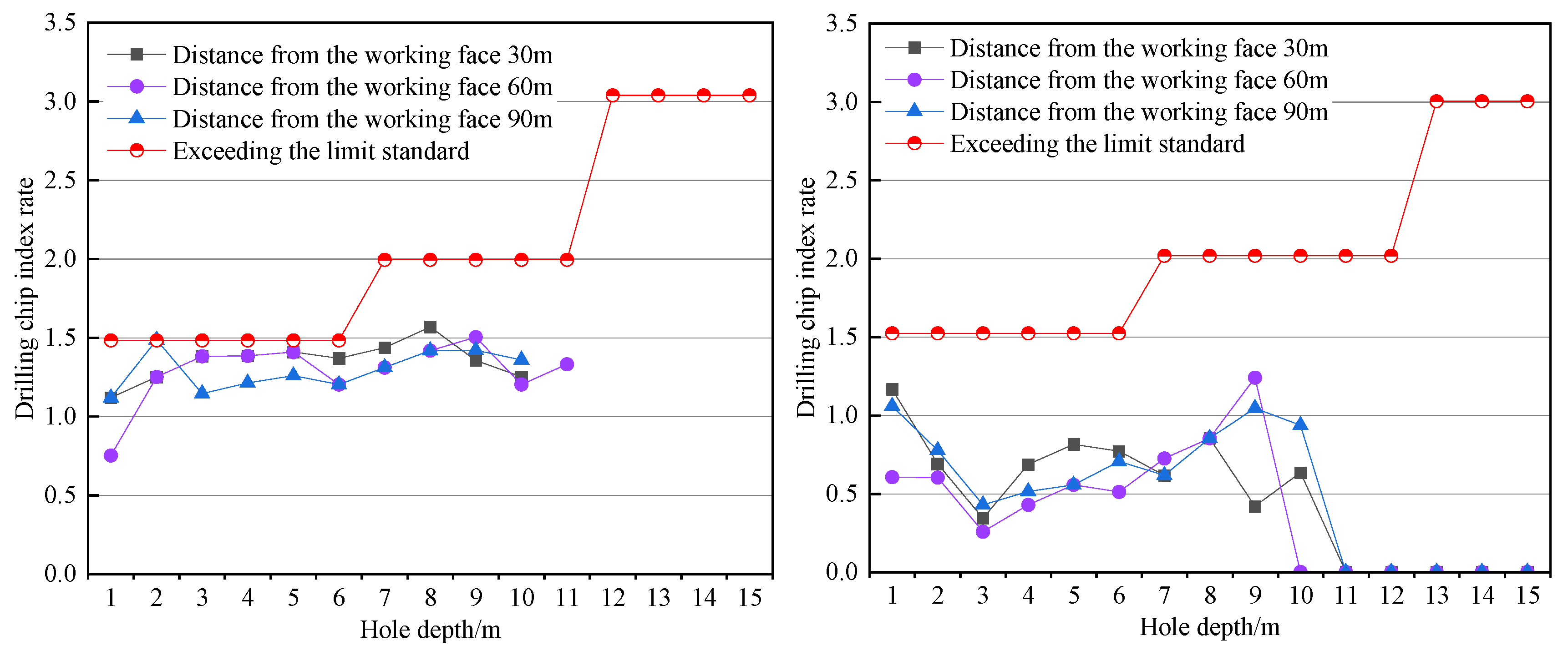
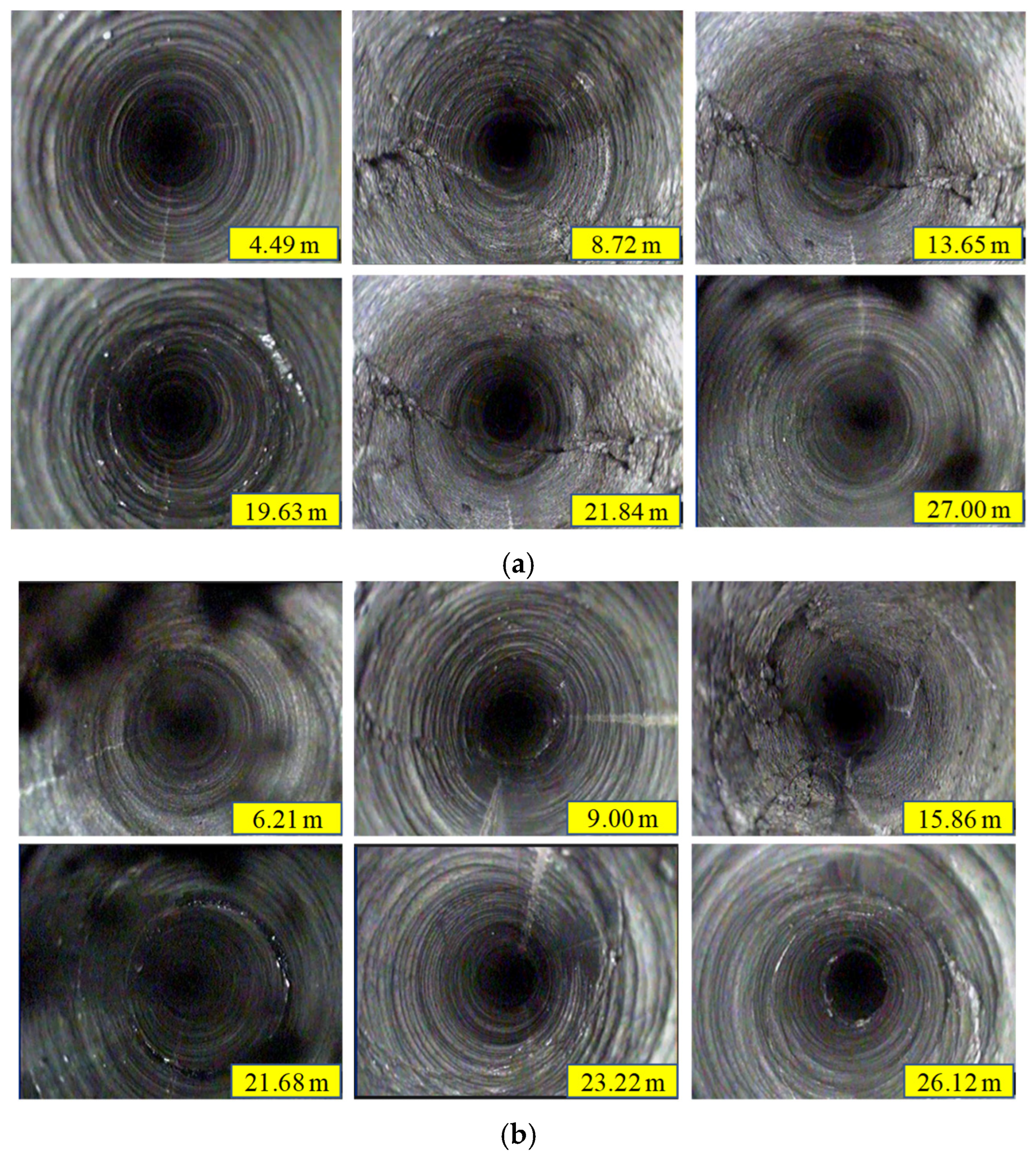
To effectively reduce the manifestation of strong mining pressure during the backfilling process of the 1310 working face, hydraulic fracturing technology was implemented in the remaining backfilling area. To grasp the control effect of mining pressure before and after hydraulic fracturing treatment of the working face roof, a monitoring station was set up 800 m away from the direction of the stopping line to monitor the remaining unmined section. The main monitoring indicators were the amount of movement of the two sides of the roadway and the top and bottom plates, drilling debris monitoring, support work resistance, etc., and drilling observation was carried out on the roof of the strong mining pressure treatment area to explore the effectiveness of hydraulic fracturing treatment measures intuitively. The monitoring results of the mining pressure control effect on the 1310 working face are shown in Figure 11, Figure 12 and Figure 13, while the drilling observation results are presented in Figure 14.
It can be inferred from Figure 11, Figure 12, Figure 13 and Figure 14 that during the mining period, as the working face moves closer to the monitoring point, the surrounding rock of the roadway shows almost no deformation at more than 150 m from the working face. The roadway deformation increases rapidly at the monitoring point within the range of 50~150 m. In contrast, within the range of 50 m, the roadway is significantly affected by mining, and the deformation of the roadway is large. The maximum displacement of the two sides before and after the strong mining pressure control is 1350 mm and 1100 mm, respectively, and the maximum displacement of the top and bottom is 950 mm and 700 mm, respectively, with a decrease of 18.5% and 26.3%. After the implementation of the governance, the deformation of the surrounding rock showed a slow change characteristic, and there was no instantaneous significant deformation phenomenon. The overall deformation process was relatively stable. By comparing the monitoring data of the drilling cuttings method (DCM) before and after the strong mining pressure treatment in the 1310 working face transportation roadway, the stress concentration of the surrounding rock of the mining roadway is relatively low during the mining process. Although it is close to the critical value, there is no situation where the drilling cutting exceed the standard limits. The amount of drilling cuttings remains at 1.25. Still, the DCM monitoring data after the strong mining pressure treatment are significantly reduced, and the amount of drilling cuttings drops to about 0.5. The average step distance for measuring point # 1 on working face 1310 is 9.6 m, and the average step distance for measuring point # 2 is 9.7 m. The overall step distance is moderate, indicating that the roof of the goaf can effectively sink, fracture, and touch the gangue; However, it should still be noted that there are also situations where the pressure step distance is 14.4 m and 12.8 m in the measuring points. When the pressure step distance increases, it is easy to cause a large area of hanging roof in the goaf. The cracks in the roof of 1310 Transportation Lane are mainly within the range of 8.72 m~21.84 m and 9.00 m~23.22 m. The crack development positions at these two locations correspond to the fracturing range of the roof fracturing holes, indicating that the cracks are densely developed in the pre-fracturing section of the high-level rock strata, and the fracturing holes promote the roof pre-fracturing. Outside the fracturing range, such as at 4.49, 6.12, 26.12, and 27 m, the stability and integrity of the borehole are good, and there is less development of fractures.

6. Discussion

This article takes Hudi Coal Mine in Jincheng City, Shanxi Province as an engineering case, studies the principle of hydraulic fracturing technology for composite hard roof, proposes the design of hydraulic fracturing scheme for composite hard roof (including layer selection and drilling parameters), uses physical similarity simulation method to study the weakening effect of fracturing rock pressure, and conducts engineering application effect measurement and analysis, achieving significant economic and social benefits. Compared with currently available publications, it presents some innovative technical solutions/research methods, and reveals more effects. Compared with traditional blasting pre-fracturing, carbon dioxide fracturing, etc., it has the advantages of low cost and high safety [25,26]. Compared with directional fracturing technology, it has the advantages of a good fracturing effect and significant weakening of mining pressure. After drilling and fracturing, there is no need for maintenance, and it can be mined along with the coal seam in the working face to achieve the timely collapse of the hard roof, thus weakening the mining pressure. At the same time, it reduces high stress concentration in coal and rock masses and improves coal seam gas permeability and extraction efficiency. Implementing this technology has significantly affected the safe and efficient production of this mine and adjacent mining areas with similar geological conditions. The technical principles are similar for weakly cemented roof rock layers or single hard rock layers, but the technical solutions and effects have certain differences [27,28]. It is necessary to optimize the technical solution parameters further, carry out engineering applications and effect measurement analysis, and expand the scope of promotion and application. In addition, fracture toughness, tensile strength, and other mechanical properties do not scale perfectly in physical simulation experiment. The sensitivity analysis (e.g., for spacing, dip angle, or pressure gradient) of drilling parameters was not conducted in this paper. This limitation will have a certain impact on the accuracy of the results to other mining conditions, which is also a topic that needs further in-depth research in the future.

7. Conclusions

(1)
Aiming to mitigate strong mining pressure in the deep composite hard roof high-gas coal seam mining in the southeastern mining area of Shanxi Province, China, a new active pressure-relief technology method with hydraulic fracturing as the core was proposed in this study. By comparing blasting-induced fracturing, water injection weakening, and hydraulic fracturing techniques, the comprehensive advantages of hydraulic fracturing in terms of construction safety, weakening accuracy, and economy were clarified. Based on the structural characteristics of the 1310 working face roof, sandy mudstone (8.05 m) and medium sandstone (6.08 m) were selected as the fracturing layers, effectively weakening the cantilever structure of the roof.
(2)
Physical analog material (PAM) experiments revealed the evolution law of overlying rock movement and stress distribution after top cutting and pressure relief. The results show that after cutting the roof, the collapse angle of the roof increases, and a complex roof structure composed of collapse zones, crack zones, and curved subsidence zones is formed above the roadway. The top plate of the left roadway shows a stress variation from a steady rise to a stable state. The stress on the top plate on the left side of the cutting line gradually increases, and the stress relief effect on the right side is significant. The vertical stress decreases from 20 to 5 MPa. The simulation verified that hydraulic fracturing effectively suppresses the accumulation of elastic strain energy induced by large-scale overhanging by forming a controllable fracture network, providing a theoretical basis for preventing and controlling strong mining pressure.
(3)
On-site monitoring data analysis proved that hydraulic fracturing technology significantly improved the manifestation of strong mining pressure. Thus, the surrounding rock deformation of the roadway significantly dropped, and after treatment, the displacement of the two sides dropped from 1350 to 1100 mm, i.e., by 18.5%. The displacement of the top and bottom plates decreased from 950 to 700 mm, i.e., by 26.3%. Data monitoring via the drilling cuttings method (DCM) proved that the drilling cuttings index rate decreased from 1.0~1.5 to below 1.0, and treatment effectively reduced the respective data. Monitoring of the support working resistance showed that the average pressure step distance was stable below 10 m per cycle. Drilling inspection confirmed that the fracturing range was approximately 8.72~23.22 m, with dense crack development and significant pre-fracturing effect.
(4)
With the increased coal seam mining depth, it became more challenging to control strong mining pressure and minimize the risks of high-gas-related disasters. In this respect, the hydraulic fracturing technology with reasonable parameter design is conducive to its wider implementation, achieving safe, efficient, and green coal mining.

Author Contributions

Q.S.: Conceptualization, Writing—review and editing. H.Y.: Data curation, Writing—original draft. Y.H.: Formal analysis and Investigation. X.C.: Software, Resources. W.R.: Methodology, Formal analysis. All authors have read and agreed to the published version of the manuscript.

Funding

The authors appreciate the financial support of this work provided by the Shaanxi Qinchuangyuan “Scientists + Engineers” Team Construction Funding Project (2025QCY-KXJ 028).

Institutional Review Board Statement

Not applicable.

Informed Consent Statement

Not applicable.

Data Availability Statement

The original contributions presented in this study are included in the article. Further inquiries can be directed to the corresponding author.

Acknowledgments

The authors would like to thank the mining company for providing monitoring data.

Conflicts of Interest

The authors declare no conflicts of interest.

References

  1. Jing, Z.R.; Min, X.Y.; Li, S.J.; Li, J.Y.; Song, W. Trade-off or synergy? The impacts of coal energy consumption on compound system vulnerability: A perspective from coal resource base assessment. Ecol. Indic. 2025, 170, 113124. [Google Scholar] [CrossRef]
  2. Guo, X.J.; Wang, X.; Wu, X.L.; Chen, X.P.; Li, Y. Carbon emission efficiency and low-carbon optimization in shanxi province under “Dual Carbon” background. Energies 2022, 15, 2369. [Google Scholar] [CrossRef]
  3. Bai, X.X.; Cao, A.Y.; Cai, W.; Wen, Y.Y.; Liu, Y.Q.; Wang, S.W.; Li, X.W. Rock burst mechanism induced by stress anomaly in roof thickness variation zone: A case study. Geomat. Nat. Hazards Risk 2022, 13, 1805–1830. [Google Scholar] [CrossRef]
  4. Koziel, K.; Skoczylas, N.; Soroko, K.; Gola, S. Gas and dolomite outbursts in ore mines-analysis of the phenomenon and the energy balance. Energies 2020, 13, 2999. [Google Scholar] [CrossRef]
  5. Ju, J.F.; Qi, C.G.; Li, Z. Effect of Thick–hard main roof fracturing on the spatiotemporal evolution of overburden fractures. Appl. Sci. 2024, 14, 10308. [Google Scholar] [CrossRef]
  6. Gao, R.; Bai, D.; Yu, B.; Tai, Y.; Meng, X.B.; Zhang, W.Y. Ground fracturing of multi-strata for strong ground pressure control in extra-thick coal seams with hard roofs: Numerical simulation and case study. Eng. Fract. Mech. 2024, 303, 1101129. [Google Scholar] [CrossRef]
  7. Pan, C.; Xia, B.W.; Yu, B.; Yu, P.; Luo, Y.F.; Gao, Y.G. Determination of the key parameters of high-position hard roofs for vertical-well stratified fracturing to release strong ground pressure behavior in extra-thick coal seam mining. Energy Sci. Eng. 2020, 8, 2216–2238. [Google Scholar] [CrossRef]
  8. Liu, T.; Lin, B.Q.; Yang, W.; Liu, T.; Xiao, W.; Zha, W. Study of effects of hard thick roof on gas migration and field experiment of roof artificially guided pre-splitting for efficient gas control. Nat. Resour. Res. 2020, 29, 1819–1841. [Google Scholar] [CrossRef]
  9. Bu, Q.W.; Tu, M.; Zhang, X.Y.; Zhang, M.; Zhao, Q.C. Analysis of energy accumulation and dispersion evolution of a thick hard roof and dynamic load response of the hydraulic support in a large space stope. Front. Earth Sci. 2022, 10, 884361. [Google Scholar] [CrossRef]
  10. Zhang, J.W.; Dong, X.K.; Bai, J.J.; Jia, L.L. The mechanism and prevention of rockburst induced by the instability of the composite hard-roof coal structure and roof fractures. Eng. Fract. Mech. 2024, 310, 110512. [Google Scholar] [CrossRef]
  11. Ma, J.K.; Li, H.; Guo, X.M.; Tian, F.C.; Guo, H.G. A control method for hydraulic fracturing of the hard roof with long and short boreholes. Front. Mater. 2022, 9, 1035815. [Google Scholar] [CrossRef]
  12. Zhang, F.T.; Wang, X.Y.; Bai, J.B.; Wu, B.W.; Wang, G.H.; Li, J.C.; Chen, D.C. Study on hydraulic fracture propagation in hard roof under abutment pressure. Rock Mech. Rock Eng. 2022, 55, 6321–6338. [Google Scholar] [CrossRef]
  13. Dou, L.T.; Yang, K.; Liu, W.J.; Chi, X.L. Mining-induced stress-fissure field evolution and the disaster-causing mechanism in the high gas working face of the deep hard strata. Geofluids 2020, 2020, 8849666. [Google Scholar] [CrossRef]
  14. Huang, B.X.; Cheng, Q.Y.; Zhao, X.L.; Kang, C. Hydraulic fracturing of hard top coal and roof for controlling gas during the initial mining stages in longwall top coal caving: A case study. J. Geophys. Eng. 2018, 15, 2492–2506. [Google Scholar] [CrossRef]
  15. Symanovych, H.; Odnovol, M.; Yakovenko, V.; Sachko, R.; Shaikhlislamova, I.; Reshetilova, T.; Stadnichuk, M. Assessing the geomechanical state of the main working network state in the case of undermining in the conditions of weak rocks. Min. Miner. Deposits 2023, 17, 91–98. [Google Scholar] [CrossRef]
  16. Symanovych, H.; Lisovytska, I.; Odnovol, M.; Ahaiev, R.; Poimanov, S. Rationale and modeling of technology for complex bottom-hole zone de-stressing of gas-dynamically active rock mass. Min. Miner. Depos. 2024, 18, 83–92. [Google Scholar] [CrossRef]
  17. Fu, Q.; Yang, J.; Gao, Y.B.; Li, C.J.; Song, H.X.; Liu, Y.X.; Wu, X. Combined blasting for protection of gob-side roadway with thick and hard roof. J. Rock Mech. Geotech. Eng. 2024, 16, 3165–3180. [Google Scholar] [CrossRef]
  18. Wang, C.G.; Bai, J.B.; Wang, T.C.; Wu, W.D. Energy Evolution Characteristics and hydraulic fracturing roof cutting technology for hard roof working face during initial mining: A case study. Appl. Sci. 2024, 14, 7405. [Google Scholar] [CrossRef]
  19. Serdyukov, S.V.; Kurlenya, M.V.; Patutin, A.V.; Rybalkin, L.A.; Shilova, T.V. Experimental test of directional hydraulic fracturing technique. J. Min. Sci. 2016, 52, 615–622. [Google Scholar] [CrossRef]
  20. Liu, Y.X.; Xu, C.H.; Xu, J.; Zeng, X.M. Hydro-mechanical coupling characteristics and weakening mechanisms of filling joint resulting from water injection. Sci. Rep. 2022, 12, 21957. [Google Scholar] [CrossRef] [PubMed]
  21. Liu, C.Y.; Yang, J.X.; Yu, B. Rock-breaking mechanism and experimental analysis of confined blasting of borehole surrounding rock. Int. J. Min. Sci. Technol. 2017, 27, 795–801. [Google Scholar] [CrossRef]
  22. Tang, X.Y.; Wan, W.; Lu, Z.X.; Chen, W. Study on composite fracture characteristics and hydraulic fracturing behavior of hard rock. Appl. Sci. 2024, 14, 2585. [Google Scholar] [CrossRef]
  23. Cao, X.; Wu, S.S.; He, Q.Y. Investigation into influences of hydraulic fracturing for hard rock weakening in underground mines. Appl. Sci. 2024, 14, 1948. [Google Scholar] [CrossRef]
  24. Sun, Q. Mechanism and Method of Key Aquiclude Strata Reconstruction by Backfill Mining Technology. Ph.D. Dissertation, China University of Mining and Technology, Xuzhou, China, 2019. [Google Scholar]
  25. Ishibashi, T.; Yamaya, Y.; Asanuma, H. Experimental insights into coupled hydraulic, mechanical, and electrical behaviors of granite fractures: Implications for indirect estimation of crustal permeability changes. Int. J. Rock Mech. Min. Sci. 2025, 188, 106060. [Google Scholar] [CrossRef]
  26. Li, X.G.; He, Y.T.; Hu, M.; Yang, Z.Z.; Wang, H.Z.; Song, R. Model for calculating the temperature and pressure within the fracture during supercritical carbon dioxide fracturing. Int. J. Hydrogen Energy 2020, 45, 8369–8384. [Google Scholar] [CrossRef]
  27. Xu, L.K.; Yu, F.H.; Tan, Y.L.; Zhang, C.; Zhou, K. The evolution of fractures in deep, weakly cemented overlying strata and the characteristics of severe and mild fracture zones. Geomech. Geophys. Geo-Energy Geo-Resour. 2024, 10, 94. [Google Scholar] [CrossRef]
  28. Shakib, J.T.; Akhgarian, E.; Ghaderi, A. The effect of hydraulic fracture characteristics on production rate in thermal EOR methods. Fuel 2015, 141, 226–235. [Google Scholar] [CrossRef]
Figure 1. 1310 working face roadway layout.
Applsci 15 10940 g001
Figure 2. The regional comprehensive lithological column.
Applsci 15 10940 g002
Figure 3. The strong mining pressure occurrence area for the 1310 working face.
Applsci 15 10940 g003
Figure 4. Roof structure and stress distribution characteristics before and after hydraulic fracturing.
Applsci 15 10940 g004
Figure 5. Hydraulic fracturing scheme design, equipment, and on-site construction drawing.
Applsci 15 10940 g005
Figure 6. Schematic diagram of laying and excavation of the physical similarity simulation model.
Applsci 15 10940 g006
Figure 7. Schematic diagram of the PAM modeling scheme.
Applsci 15 10940 g007
Figure 8. The movement law of overlying strata in the 1310 working face during mining.
Applsci 15 10940 g008
Figure 9. Stress distribution curve of adjacent tunnels and coal pillars caused by coal mining.
Applsci 15 10940 g009
Figure 10. Stress distribution curve of the top plate on both sides of the cutting line.
Applsci 15 10940 g010
Figure 11. Deformation curves of the surrounding rock in the 1310 working face before and after hydraulic fracturing.
Applsci 15 10940 g011
Figure 12. Monitoring curves of coal drilling cuttings in working face 1310 before and after hydraulic fracturing.
Applsci 15 10940 g012
Figure 13. Monitoring curve of working resistance of 1310 working face support: (a) #1 measuring point; (b) #2 measuring points.
Applsci 15 10940 g013aApplsci 15 10940 g013b
Figure 14. Roof fracture development in working face 1310 after hydraulic fracturing: (a) #1 drilling hole; (b) #2 boreholes.
Applsci 15 10940 g014
Table 1. Parameters related to the fragmentation height of the roof rock.
LithologyThickness (m)Fragmentation CoefficientFragmentation Height (m)Accumulated Fragmentation Height (m)Cumulative Height of Roof (m)
Medium sandstone6.08 1.31.82 6.21 25.13
Sandy mudstone1.65 1.20.33 4.39 19.05
Medium and fine sandstone5.10 1.31.53 4.06 17.40
Sandy mudstone8.05 1.21.61 2.53 12.30
Mudstone1.05 1.20.21 0.92 4.25
Siltstone3.20 1.20.64 0.71 3.20
#3 Coal4.851.20.07----
Table 2. PAM parameters used to simulate the coal and rock strata mechanical properties.
LithologySand
(kg)
Calcium Carbonate
(kg)
Gypsum
(kg)
Thickness
(cm)
PAM Strength (kPa)
Medium sandstone36.16 1.81 4.222.50311.11
Siltstone42.33 4.94 2.11 2.6765.11
Sandy mudstone20.00 2.00 4.67 1.2176.44
Medium sandstone63.99 6.40 2.74 4.05311.11
Sandy mudstone12.83 0.64 1.49 1.1076.44
Siltstone54.00 2.70 6.30 3.4065.11
Sandy mudstone84.37 8.44 19.69 5.3776.44
Mudstone10.13 1.01 2.36 0.70179.07
Siltstone26.61 1.33 3.11 2.1365.11
#3 Coal36.72 3.67 1.57 3.1769.33
Sandy mudstone62.44 6.25 14.57 4.6076.44
Siltstone32.65 3.27 7.62 2.3165.11
Disclaimer/Publisher’s Note: The statements, opinions and data contained in all publications are solely those of the individual author(s) and contributor(s) and not of MDPI and/or the editor(s). MDPI and/or the editor(s) disclaim responsibility for any injury to people or property resulting from any ideas, methods, instructions or products referred to in the content.