1. Introduction
In order to make road transport as sustainable as possible, more and more vehicles are being electrified every year [
1,
2]. Although electric drives have a number of advantages over conventional powertrains, regenerative braking is one of the most widely used and well-proven braking optimization systems that contribute to improving the efficiency of electric vehicles (EVs) [
3,
4]. Regenerative braking systems were already used in the first mass-produced hybrid cars [
5]. This system allows part of the braking energy to be stored in batteries, thereby reducing energy loss during braking due to heat dissipation; moreover, regenerative braking reduces the release of harmful substances from the friction of the brake pads and tires [
6]. As a result, all currently available EVs have regenerative braking systems, the intensity of which can often be selected by the driver. The increased mass of electric vehicles in certain driving modes can increase the efficiency of regeneration due to higher kinetic energy but at the same time have a negative impact on the road surface [
7]; however, this research is more focused on driving stability and safety [
8].
Despite all the requirements for drive efficiency, vehicle stability is one of the most important factors in vehicle safety [
9]. From the perspective of vehicle dynamics, stability depends on the contact forces generated by the tires, which are influenced by the chassis’ response to changing driving conditions. In EVS, regenerative braking directly affects the braking torque of the car, which also has an effect on its stability. This is particularly noticeable in rear-wheel-drive (RWD) vehicles, as a loss of traction on the rear axle results in dangerous oversteer [
10]; however, a demand for directional stability is also evaluated for EVs braking [
11]. Here, hydraulic brake compensation-based method and the regenerative brake robust control-based method were simulated and compared with conventional control. Results showed a promising reduction in lateral displacement of the vehicle center of gravity from 0.5 m to 0.1 m.
In regenerative braking systems, part of the braking force is generated by an electric motor; however, an electric motor does not have as much braking force as friction brakes can generate [
12]. Also, in order to achieve the maximum level of regenerated energy, it is necessary to brake as much as possible with the electric motor and only use friction brakes when the braking force generated by regeneration is insufficient [
13]. This must be implemented, ensuring requirements for brake force proportioning, maximum efficiency for braking performance, and reliability [
14,
15]. Moreover, neural network tools have been used for design and performance analysis of EVs, which showed promising results in fine-tuning between braking efficiency and energy generation [
16,
17].
Electric drive brakes are usually connected to an additional control unit and are classified as electrohydraulic, electromechanical, electromagnetic, or hybrid. The actual braking force is determined by a specific control unit based on the information sent by the pedal sensors. For example, electrohydraulic brakes work in such a way that sensors on the brake pedal calculate how hard the brake pedal is pressed, and based on the calculated pressure, the main brake cylinder creates hydraulic fluid pressure that acts on the brake pads. Electromechanical or electromagnetic brakes work in the same way; only the system that creates the pressure acting on the brake pads changes accordingly [
18]. During regenerative braking, friction brakes are used in addition to electric brakes; therefore, strategies are needed that define how the regenerative system works in conjunction with friction brakes. Based on the strategies used, regenerative braking is divided into series and parallel architecture [
19]. In addition to this technology, a non-contact braking system based on magnetic field sources instead of friction elements has already been introduced as a potential for lightweight EVs [
20].
Another publications directed to energy flow analysis during regenerative braking use additionally ecology and racing strategy based on fuzzy logic distribution [
21]. The variation between 21% and 42% for recaptured energy was found using different regenerative braking strategies.
According to research conducted by Hancock and Assadian [
12] regenerative braking acting on the rear axle of a car has a negative impact on its stability. Electronic Stability Program (ESP) helps maintain stability when driving on good road surfaces, but in poor road conditions even stability programs cannot prevent rear axle skidding. It can be assumed that ESP does not function optimally on slippery road surfaces, as regenerative braking affects ESP wheel control. During regenerative braking, the vehicle generates significantly more braking force on the rear axle. The simulations performed by [
12] are quite limited by the mathematical model of the car used and only include basic data in the calculations, while the dynamics of the braking system, transmission, and chassis are not included.
The regenerative braking system and its improvement are discussed in other studies and articles [
22,
23,
24]. However, much more attention is paid to testing new strategies and algorithms rather than researching regenerative systems already used in electric vehicles under a wide range of driving conditions or modes.
Tur et al. [
25] conducted a study in which the tested system used an electric motor from EV and an ABS [
24]. Both publications state that electric motors can generate the required braking or acceleration torque almost instantly, which allows them to be used as a very fast and accurate ABS. Such a system was tested with a real electric vehicle in the work of [
24]. In order to implement the use of an electric motor as an ABS, the authors developed a control algorithm that divides the braking force into dynamic and static components. Although the algorithm is based on a serial regenerative braking strategy (friction brakes only start to operate when the braking force from regenerative braking is insufficient), the strategy is improved by adding ABS operating conditions. This solution is one of several ways to solve the stability problem during regenerative braking, but this study uses a front-wheel drive car and does not take into account cornering stability.
Research by Yao et al. (2020) [
26] proves that ABS logic and regenerative braking of EVs must be coordinated. Authors point out that if ABS takes over and shuts down regen abruptly, wheel torque changes discontinuously, creating transient yaw or pitch responses, which should be solved with integrated control strategies between ABS and regenerative braking control [
26]. Moreover, hierarchical cooperative control can coordinate motor torque controllers and hydraulic/electronic brake actuators to ensure smooth torque transitions; however, only HIL test bench-based test, were conducted to prove this [
27]. The same research conditions without field tests were used for anti-lock regenerative braking control using sliding mode integration [
28]. It should be mentioned that brake-by-wire architecture becomes a promising technology for EVs; however, it is also found that brake-by-wire and motor controllers can enact torque fast, but mismatches in timing between mechanical friction brakes, motor regen control, and ABS can produce step changes [
29].
Le Solliec et al. [
22] investigate a new regenerative braking control system where electric motors are located in the rear wheels (in-wheel motors). This means that the torque of each wheel can be controlled separately, and possibly even implement the ESP system. The advantage of in-wheel motors is that they provide very fast and precise torque transfer to each drive wheel, as the wheel itself is an electric motor; however, the increased unsprung mass poses new challenges in suspension design [
30]. Using this technology, a regenerative system can be created in the rear wheels of a car that very precisely controls the braking torque of each wheel during regeneration, preventing loss of traction when driving in poor road conditions, both in a straight line and when cornering [
22]. Adding to this, car yaw moment control based on torque vectoring with multiple motors EVs’ architecture is capable of achieving high regenerative braking with yaw transients. Therefore, maximal regeneration should be constrained due to car stability [
31,
32]. Another research investigated how the use of in-wheel motors on the rear wheels affects the distribution of braking force between the front and rear axles and how mathematical tire models developed by H. Paceik and D. Dugoff can be used to calculate the torque transmitted to electric motors.
Both Le Solliec [
22] and Hamada & Orhan [
29] or Li et al. [
23] discuss that regenerative braking affects the stability of a car, and new strategies are identified as a way to improve stability, but how new algorithms improve car stability under real conditions has not been investigated.
After analyzing the patents of Tesla, one of the most popular electric car manufacturers, it can be seen that the information used by the car to maintain traction in normal driving mode is also used for the regenerative braking function [
33]. Engine speeds, steering angle, brake pedal position, and torque transfer are also monitored. The manufacturer itself has conducted detailed studies of the EV it produces on different traction surfaces [
34]. This article also mentions that traction control is used during regenerative braking. By monitoring wheel speed, it is possible to determine when the wheels are slipping and then limit the regenerative braking torque until the wheel regains traction with the road [
34].
Based on this, it can be stated that among other technological challenges of regenerative braking, such as energy recovery and control algorithm optimization for effective energy storage, its incorporation among current braking systems (ABS, ESP) makes this topic still relevant even with modern control strategies [
3]. Moreover, from the literature review, it was found that low-latency estimation under varied surface and environmental conditions remains difficult, and extensive scenario-based simulation with experimental validation is needed. As braking becomes more software-defined, ensuring fail-operational performance is crucial. For these purposes, a corner-braking tests with emergency maneuvers on low-grip surfaces are required to reveal edge-case instabilities.
Based on the previous research and studies, it can be assumed that further research on regenerative braking systems in the context of vehicle stability is valuable, and strategies for improving the systems can be easily integrated into the systems if they are contained within software control. This research is further organized in the following order: the materials and methods used for research are presented in
Section 2. In
Section 3, the experimental research with evaluation of the collected data is presented. In
Section 4, computer simulation based on field tests and extended conditions is presented.
Section 5 discusses the results of conducted research and presents the new regenerative braking control strategies. Finally,
Section 6 concludes the paper.
2. Materials and Methods
Experimental and theoretical research was conducted to analyze the stability issues of rear-wheel drive electric vehicles (EVs) during regenerative braking. This research combined both field testing and dynamic modeling to better understand how regenerative braking impacts vehicle control, particularly in low-grip conditions. The field tests were carried out in a controlled environment with an artificially slippery surface, while the theoretical study involved creating a dynamic model of an EV with regenerative braking on the rear axle using MATLAB/Simulink (R2024a). To compare real-world performance with simulations, two rear–wheel–drive EVs—the Volkswagen ID.3 and the Tesla Model 3 Standard Range—were selected for both the track tests and the simulations. These vehicles were chosen for their popularity and differing regenerative braking strategies, providing valuable insights into the stability challenges of such systems.
The regenerative braking process in these vehicles operates differently depending on the driver’s input. When the accelerator is released in the Volkswagen ID.3, the system engages a low regeneration force, achieving a deceleration of up to 0.13 G, which creates a sensation of “free force” in the car. Upon pressing the brake pedal, maximum regenerative force is applied, resulting in a deceleration of up to 0.3 G. This regenerative braking force, though less than full braking, still has an impact on vehicle dynamics. Other manufacturers’ EVs exhibit similar behavior, with deceleration forces ranging from 0.18 G to 0.2 G when the accelerator is released [
27,
28]. In the case of the Tesla Model 3 Standard Range, which is powered by a single electric motor on the rear axle, regeneration begins as soon as the accelerator is released. In the tests conducted, the maximum regenerative braking torque on the rear axle reached 378 Nm for the VW ID.3 and 535 Nm for the Tesla Model 3.
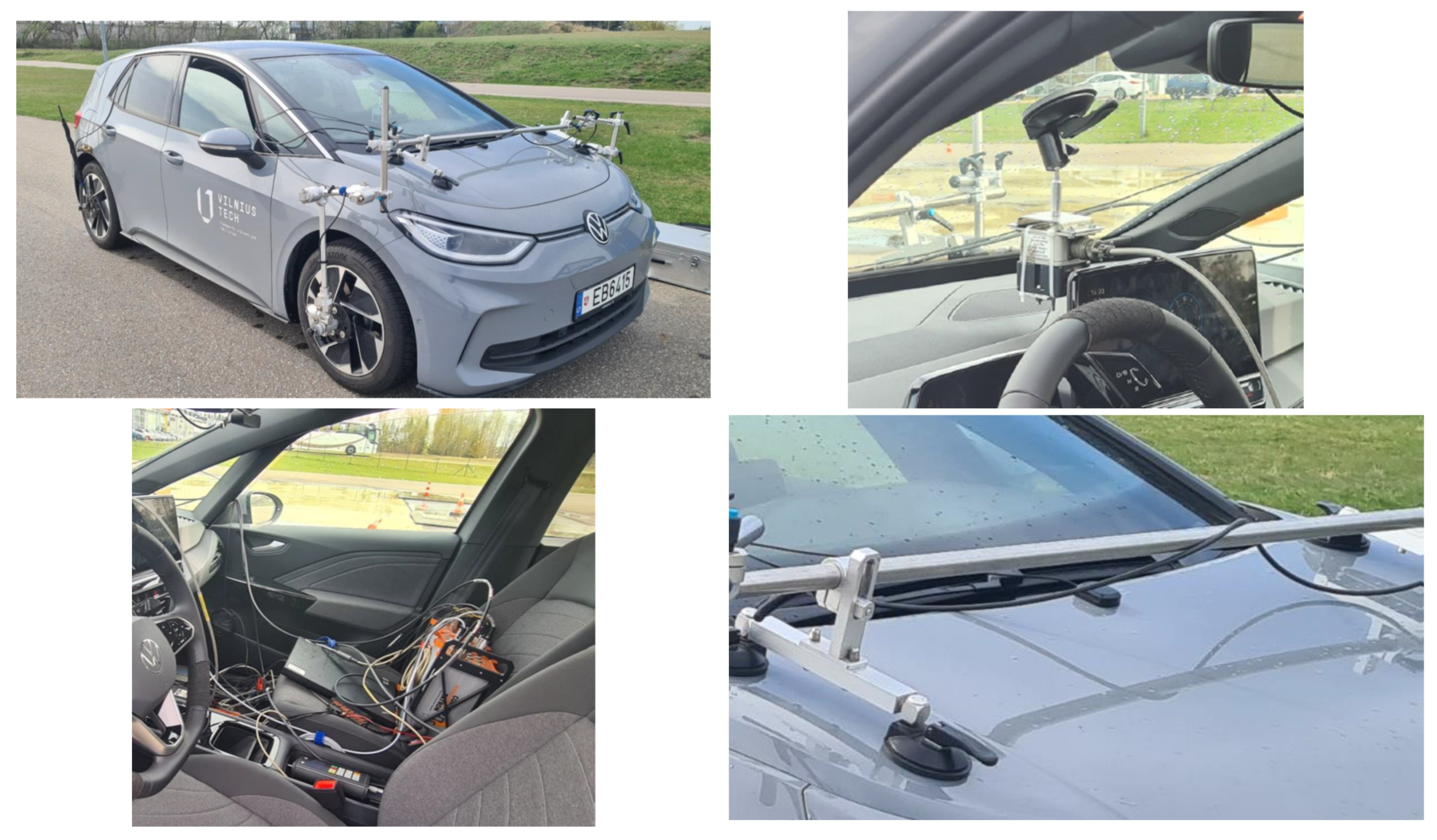
Equipment from the Kistler group (Sindelfingen, Germany) was used in electric vehicles during the experimental research, which enabled the measurement of vehicle yaw rate, angular speed for each wheel, position of the accelerator pedal, vehicle speed, and longitudinal and lateral acceleration (
Figure 1). A separate GPS sensor was used to track the movement trajectory.
Yaw rate as well as longitudinal and lateral motion allow us to calculate the car’s movement in space and the side-slip angle, which helps to determine the level of loss of stability. The rotational speeds of the wheels allow the relative slip of each wheel to be compared at any moment during a turn. If a wheel has excess speed or loses speed very quickly compared to the other wheels, it can be assumed that the wheel has reduced traction with the road surface. The position of the accelerator allows us to monitor when the driver releases the pedal and thus determine when regenerative braking is activated.
The Tesla car is connected to the cloud, so its wheel speeds, rotational speed, accelerator pedal position, car speed, and torque generated by the electric motor were also recorded.
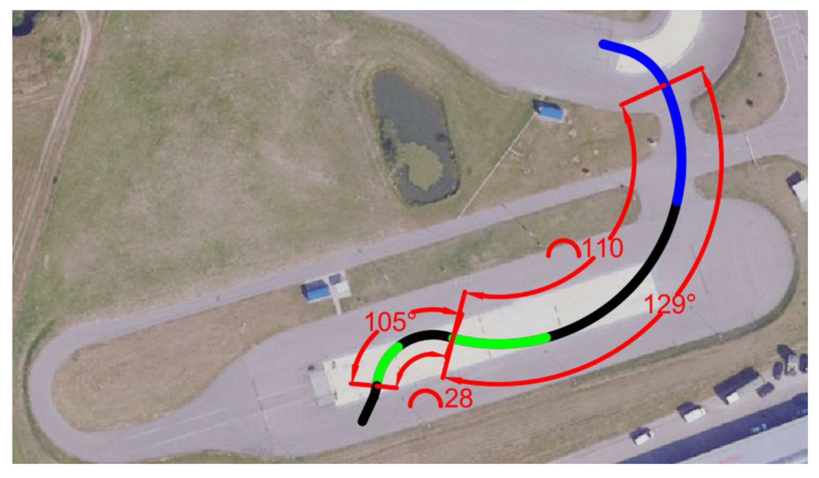
A two-turn maneuver was chosen as the main test maneuver. The electric vehicle was driven through two turns without braking with the brake pedal. The data recorded by the equipment enables us to determine whether the electric vehicle starts to slip due to the activation of the regenerative system or due to a simple loss of traction caused by excessive speed on a slippery turn. The maneuver performed is shown in
Figure 2.
The blue line in
Figure 2 corresponds to the acceleration zone, when the accelerator is pressed until the set speed of approximately 50 km/h is reached. The speed is reached at approximately the point where the line changes to black. In these sections, the driver maintains a constant speed and a constant turn. The first black zone is a right turn that continues on both dry asphalt and slippery pavement. This allows us to check whether the electric car is stable enough not to lose stability when driving at a constant turn and without braking. If the tested EV loses stability at this maneuvering point, it means that the speed is too high or the maneuver is too sudden, and the car loses stability without regenerative braking intervention. However, if the car maintains stability throughout the black zone, it approaches the green zone, which means the start of regenerative braking. In the green maneuvering zone, the driver must maintain the turn and completely release the accelerator pedal. When regenerative braking is activated, the rear wheels of the electric vehicle will be affected by additional braking torque, which may cause a loss of wheel traction and a reduction in vehicle stability. After the first use of regenerative braking, a turn to the left with a smaller radius follows. Since the car has already slowed down, the speed drops to about 35 km/h. This second turn on slippery pavement allows us to observe how the results change when the car is driving slower but with a sharper turn. The maneuver is performed several times with regenerative braking turned on and off.
The turns in this maneuver are 129 degrees and 105 degrees. These angles were chosen due to the limitations of the test facility. Since the aim of the test was to perform the sharpest possible turn, these maneuvers were the most suitable for this track.
The dynamic modeling and testing of the electric vehicle model were carried out using MATLAB/Simulink. The simulated vehicle model is composed of distinct subsystems, which enables a detailed examination of the influence of each component on overall stability. After conducting the initial simulations and comparing the results with experimental data from real electric vehicle tests, additional simulations were performed to investigate the contribution of each stability-related subsystem to the outcomes of the primary simulations.
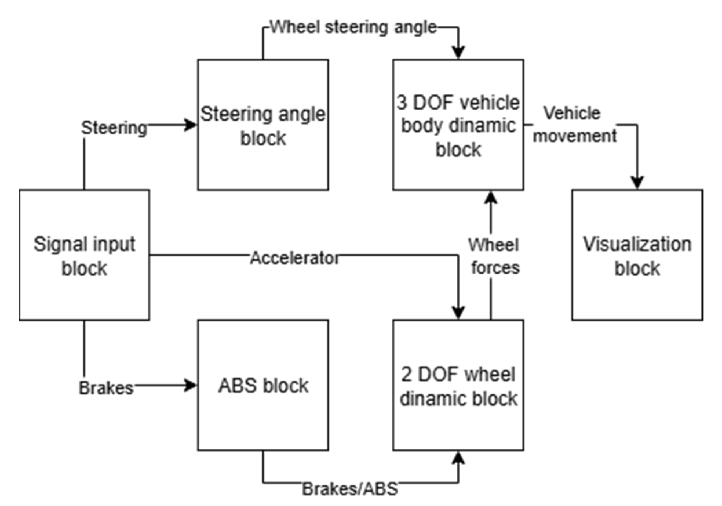
Figure 3 presents a basic overall schematic of the simulation model, in which the signal input block, steering mechanism block, braking system with ABS block, two degrees-of-freedom (DOF) wheel dynamics block, three DOF vehicle body dynamics block, and the output and visualization block for motion characteristics are arranged sequentially.
The Signal input block is responsible for generating initial inputs or driver control signals. This is the first block in the simulation chain, producing pedal and steering wheel angle data. The signals range from 0 to 1 for the accelerator and brakes. Steering signal is measured in degrees, and accordingly, negative degrees turn the wheels left and positive degrees turn the wheels right. This signal is then converted from degrees to radians before entering the steering angle block.
The steering angle block implements a kinematic steering model to calculate the wheel angles according to the selected steering mechanism. Configured as ideal Ackerman. The left (
δL) and right (
δR) wheel angles are calculated using a refined version of the Ackermann steering geometry that considers the wheelbase (WB) and track width (TW). Given an input steering angle
δAck (in radians), the block computes the steering angles for the front wheels using the following formulas:
here,
WB represents the wheelbase (the distance between the front and rear axles), and
TW is the track width (the distance between the left and right wheels). The input steering angle
δAck is normalized with a factor of 0.5 radians to ensure it stays within realistic limits for a passenger car. These formulas calculate the left and right wheel angles based on the geometry of the vehicle, ensuring proper steering behavior and accurate cornering dynamics.
The ABS block is positioned before the wheel block, since it ensures stability by independently controlling braking at each wheel. This block processes multiple inputs, including yaw rate, wheel slip, vehicle speed, and brake signals, to determine whether the car is slipping and requires ABS intervention or sliding in a corner, triggering ESP for enhanced stability. The block integrates a separate signal frequency generator to deliver the high-frequency signals required by ABS, ensuring real-time responsiveness. The wheel and tire block determines tire–road interaction and generates the motion forces transmitted to the vehicle body block. This block is also essential for brake signal processing: in the model, the brake signal together with the wheel and tire block simulate regenerative braking, as well as ABS and ESP operation. Braking torques are applied at the rear wheels to replicate regenerative braking in the case of a single-axle drive configuration. Two key signals that play a critical role in the model are the brake pressure and axial torque (accelerator). Before entering the wheel block, the accelerator signal passes through a differential block, which adjusts the input based on the vehicle’s dynamic behavior. The brake signal, on the other hand, is provided by the ABS block, which determines when ABS intervention is required based on vehicle slip conditions.
Inside the wheel block, the forces acting on the wheel axle are calculated using the Magic Formula tire model, a widely used empirical model for tire-road interaction. The Magic Formula provides a mathematical relationship between the tire slip (both longitudinal and lateral) and the forces generated at the contact patch. The formula is given by the following:
where
F is the force (longitudinal or lateral depending on the type of slip), α is the slip ratio (for longitudinal slip) or slip angle (for lateral slip), and B, C, D, and E are empirical coefficients that define the tire’s characteristics.
The coefficients B, C, D, and E are derived from tire testing data and represent tire stiffness, peak force, shape of the curve, and a slip sensitivity factor, respectively. By utilizing the Magic Formula, the model accurately simulates how the tire responds to changes in slip, brake pressure, and accelerator input. This allows for more realistic simulation of tire forces under varying driving conditions, providing valuable insights into vehicle handling and stability.
Finally, the vehicle body block computes the vehicle body (full-vehicle) dynamics—velocities, accelerations, and trajectories—based on the wheel forces and steering angle, and transmits these results to the visualization block. The block assumes that the externally provided forces are in the vehicle-fixed frame at the axle-wheel location as follows:
where
Fxft—longitudinal force at the front axle,
Fyft—lateral force at the front axle,
Fxf_input—the input longitudinal force at the front axle, typically coming from the accelerator or brake pedal,
Fyf_input—the input lateral force at the front axle, typically coming from the steering input,
Fxf_T—the total longitudinal force at the front axle, which includes both the input force and any additional forces resulting from tire-road interaction, vehicle slip, etc.,
Fyf_T—the total lateral force at the front axle, similarly including both the input force and forces due to the vehicle’s dynamics,
Fxr—longitudinal force at the rear axle,
Fyr—lateral force at the rear axle,
Fxr_input—the input longitudinal force at the rear axle, typically from the engine (for a rear-wheel-drive car) or from braking forces,
Fyr_input—the input lateral force at the rear axle, which may arise from the rear tires’ reaction to steering and road conditions,
Fxr_T—rhe total longitudinal force at the rear axle, which includes input force and any effects from tire dynamics, load transfer, and road interaction,
Fyr_T—the total lateral force at the rear axle, including contributions from the vehicle’s dynamic behavior during cornering or sliding.
The 3-DOF vehicle body block in Simulink is an effective tool for simulating a car’s behavior while cornering on slippery surfaces. By modeling longitudinal, lateral, and yaw motion, it provides a comprehensive view of the vehicle’s dynamics in low-traction conditions, such as icy or wet roads. The block simulates how the vehicle responds to steering and braking forces, capturing key behaviors like oversteering or understeering during turns. Its ability to model tire-road interactions, along with the dynamic behavior of both the front and rear axles, makes it ideal for testing vehicle stability and safety systems like Electronic Stability Program (ESP). The 3-DOF block strikes a balance between accuracy and computational efficiency, making it a valuable tool for analyzing vehicle handling and optimizing control systems in real-world driving scenarios with regenerative braking.
The parameters for the block also need to be set for each specific car. The Kinematic Steering Block includes key parameters such as percent Ackermann, steering ratio, steering range, wheelbase, and track width. Percent Ackermann determines the geometry of the steering system, defining how the inner and outer wheels rotate in relation to one another during turns. The steering ratio describes the ratio of the steering wheel angle to the angle of the wheels, influencing the sensitivity and response of the steering system. The steering range refers to the maximum angle that the wheels can turn, which directly impacts the vehicle’s turning radius. Wheelbase defines the distance between the front and rear axles, affecting stability and maneuverability, while track width refers to the distance between the left and right wheels, influencing the vehicle’s handling and cornering dynamics.
The Combined Slip Wheel 2DOF Block models the interaction between the tires and the road surface. Its key parameters include tire dimensions (such as tire width and radius), weight distribution across the tires, tire pressure, and the type of tire being used (e.g., summer, winter, or all-season). These parameters are critical because they define the tire’s contact patch, load distribution, and friction characteristics, all of which play a vital role in the vehicle’s stability during cornering, braking, and acceleration. The tire dimensions impact how much the tire deforms under load, while tire pressure affects the tire’s contact area and grip level. The tire type determines the overall friction and behavior on different road surfaces, which is essential for modeling tire performance under various conditions. Furthermore, scale factors are crucial in calibrating the model to ensure the real-world accuracy of the simulation. The friction coefficient can be adjusted in these blocks to simulate different road conditions, such as poor grip surfaces (e.g., wet or icy roads), affecting the tire’s ability to generate traction and altering the vehicle’s stability during maneuvers.
The Vehicle Body 3DOF Dual Track Block models the overall dynamics of the vehicle, with important parameters such as the number of wheels, vehicle mass, track width, and the environment in which the vehicle is being simulated. The number of wheels affects the vehicle’s overall stability and load distribution. The vehicle mass influences the inertial properties of the car, impacting its response to forces during acceleration, braking, and cornering. The track width affects the vehicle’s handling characteristics, particularly its cornering stability. Additionally, it is essential to define the environment for the simulation, such as road conditions (e.g., dry, wet, or icy), as these conditions influence how the vehicle behaves under different driving scenarios, including the effects of tire grip and road surface interactions.
Finally, the custom ABS/ESP block plays a crucial role in maintaining vehicle stability by adjusting the braking forces on individual wheels. This block takes inputs such as brake pressure (P_brake), wheel slip (slip_ratio), and yaw rate (yaw_dot) to determine the optimal brake force distribution. The brake pressure parameter controls the amount of braking force applied, while the wheel slip provides feedback on how much the tire is slipping relative to the road surface. The yaw rate is critical for determining the vehicle’s rotational behavior, and the ESP system adjusts braking forces to prevent instability, such as oversteer or understeer.
To ensure the accuracy of the simulation, each of these parameters must be set according to the specific vehicle being simulated. This allows the model to replicate real-world dynamics and provide valuable insights into vehicle performance under various conditions. Adjusting these parameters ensures that the model reflects the true handling, stability, and tire-road interactions of the vehicle.
3. Experimental Research
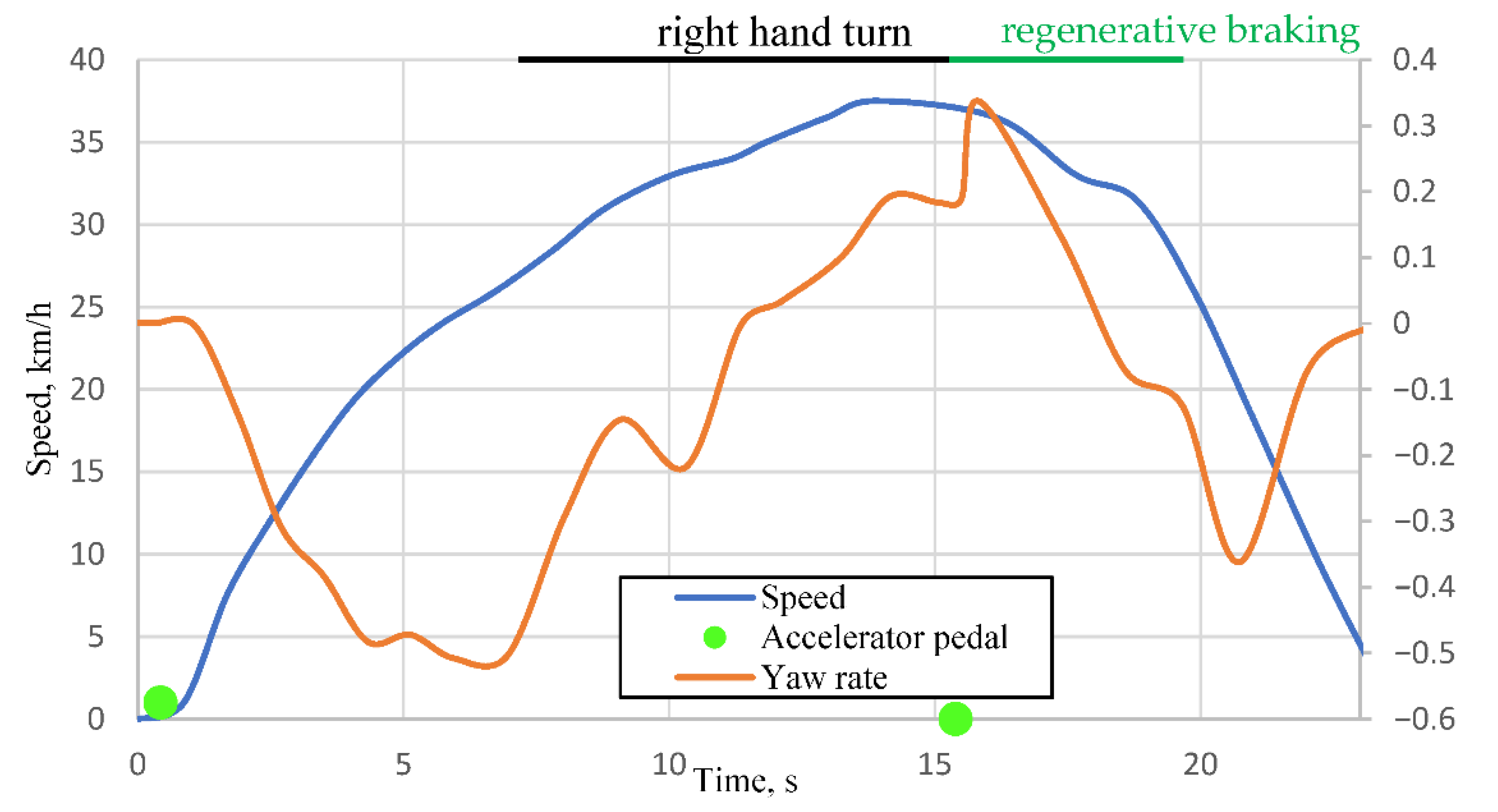
The preliminary results of the experimental research indicate that the stability of electric vehicles deteriorates during regenerative braking. An intervention of the Electronic Stability Program (ESP) in vehicle control becomes evident when the accelerator pedal is released on a curved, low-grip road surface. This shows that the vehicle’s sensor system detects the onset of instability and immediately initiates corrective actions to restore stability. For a short interval—immediately following the activation of regenerative braking—the vehicle exhibits noticeable skidding and a tendency to rotate in the direction of the turn. Subsequently, the ESP system actively compensates for the excessive oversteer, which is accompanied by activation of the Anti-lock Braking System (ABS). The recorded data are presented in
Figure 4.
In
Figure 4, the green markers represent accelerator pedal positions. The first marker (value 1) corresponds to pedal depression, which remains constant until the second marker, indicating pedal release (value 0). It can be observed from the orange curve in the graph that the maneuver begins with a right-hand turn, followed by a left-hand turn, during which the accelerator pedal is released at 15.39 s. Due to the mounting position of the yaw rate sensor, the negative yaw rate represents the car turning left, and the positive represents the car turning right. Comparing
Figure 2, the beginning of the maneuver is a long right-hand turn with a regenerative braking zone indicated in green. We can see in
Figure 3 that from 1 s to 7 s the car is getting into position for the maneuver, and the maneuver begins at 7 s as a right turn indicated by a positive yaw rate. At 15.39 s the car comes into the regenerative braking zone (green zone in
Figure 2) and begins regenerative braking. Based on the yaw rate (orange curve), an increase in angular velocity is observed from 0.189 rad/s (at 15.5 s) to 0.337 rad/s (at 15.85 s), corresponding to a change of 8.48 °/s and a yaw acceleration of 0.457 rad/s
2. The maximum yaw acceleration of the vehicle during regenerative braking was found to be 0.188 °/s
2. Very similar results were consistently obtained in subsequent experiments.
In the test drive illustrated in
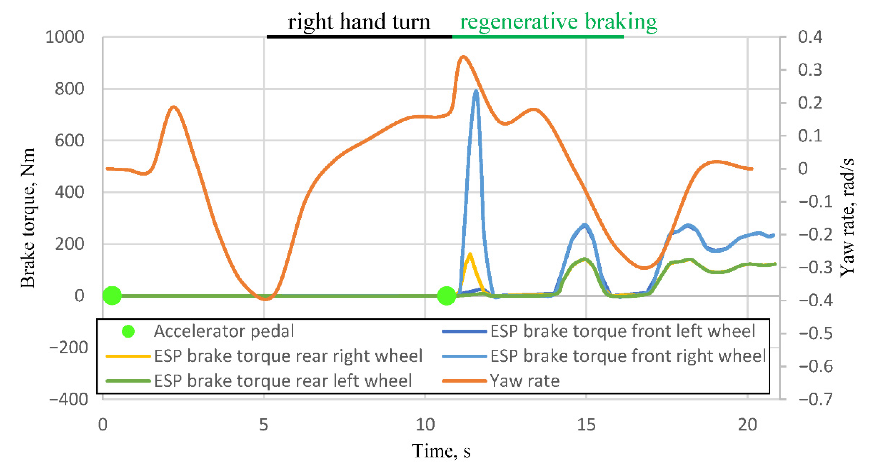
Figure 5, the accelerator pedal was released at 10.67 s (second green marker). The change in yaw rate from 5 s corresponds to a steadily increasing left-hand turn maneuver. At approximately 9 s, the yaw rate stabilizes at a constant value of 0.15 rad/s (8.59 °/s). After the onset of regenerative braking (following 10.67 s), the yaw rate increases to 0.34 rad/s (19.48 °/s) within 0.53 s, corresponding to an acceleration of 20.4 °/s
2. Such abrupt variations demonstrate a reduction in stability precisely at the moment when regenerative braking is activated. Accordingly, both in
Figure 3 and
Figure 4, after the initial decrease in stability at the onset of regenerative braking, the vehicle returns to its previous stable trajectory (the yaw rate resumes a controlled progression).
Figure 6 presents additional ESP system signals recorded during the maneuver performed in Test 6.
These signals are transmitted to the ABS as commands to generate specific braking torque at each wheel. Based on these signals, it can be confirmed that the electric vehicle detected a reduction in stability starting at 10.67 s, leading to braking commands being applied to the front right and rear right wheels. The front wheel received a braking torque of 789 Nm at 11.59 s, while the rear wheel received 162 Nm at 11.39 s. Since the maneuver involved a left-hand turn, it can be concluded that the activation of regenerative braking induced excessive oversteer. Consequently, the ESP system intervened by braking the wheels on the right-hand side, thereby mitigating the oversteer effect.
In summary, conducted field experiments demonstrated a reduction in stability during cornering with regenerative braking on a low-grip surface. This was evidenced by the sharp increase in yaw rate at the onset of regenerative braking and the subsequent activation of the ESP system. However, complete loss of stability was not observed, as the intervention of the ESP system enabled both electric vehicles to maintain overall stability. According to its operating principle, ESP has an inevitable delay as it only reacts to the movement of a vehicle that has already lost stability; therefore, it makes sense to coordinate the operation of regenerative braking and to avoid instability in the initial stage.
4. Simulation
The initial simulations were designed to replicate the real-world test conditions described in
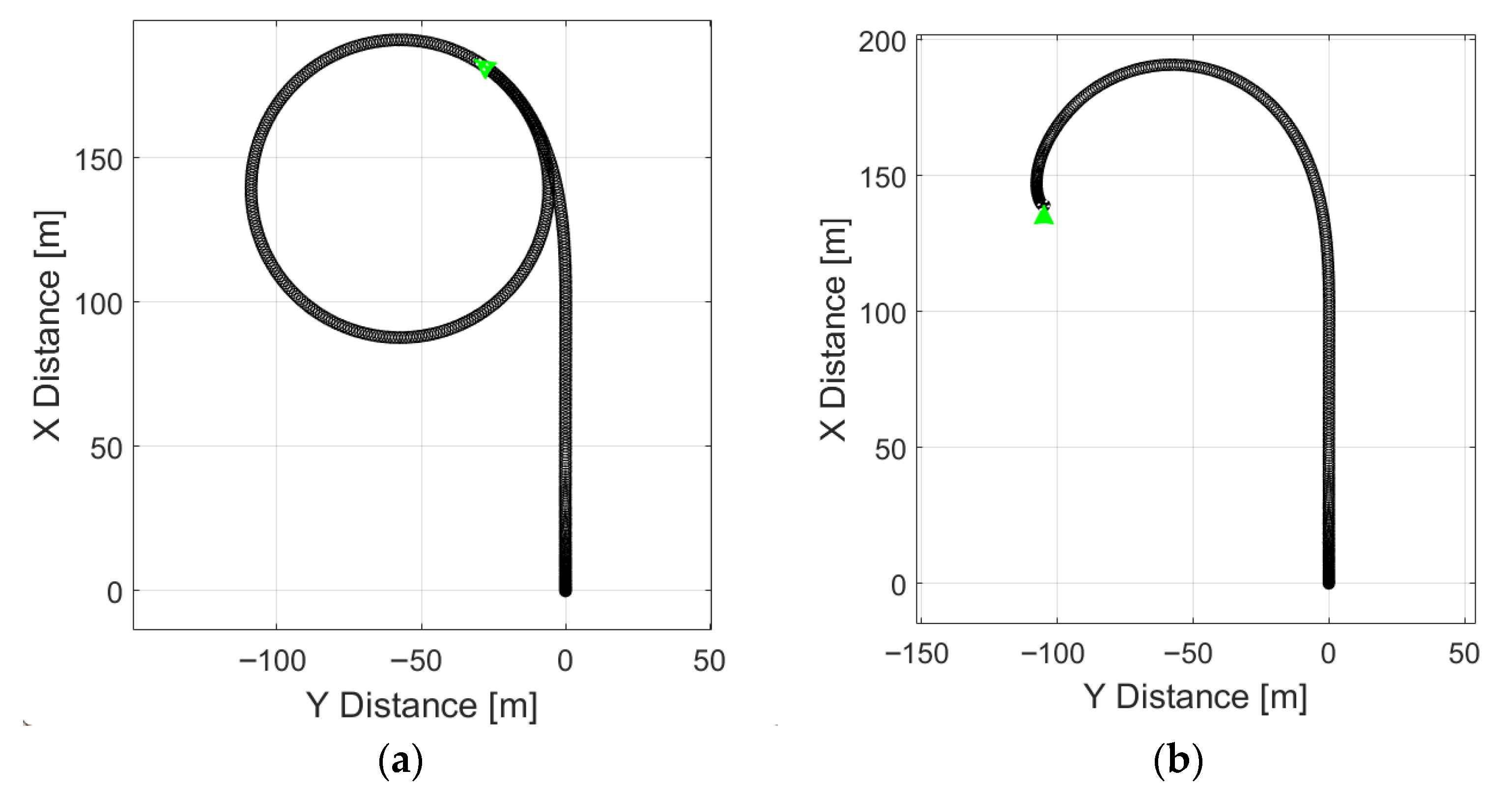
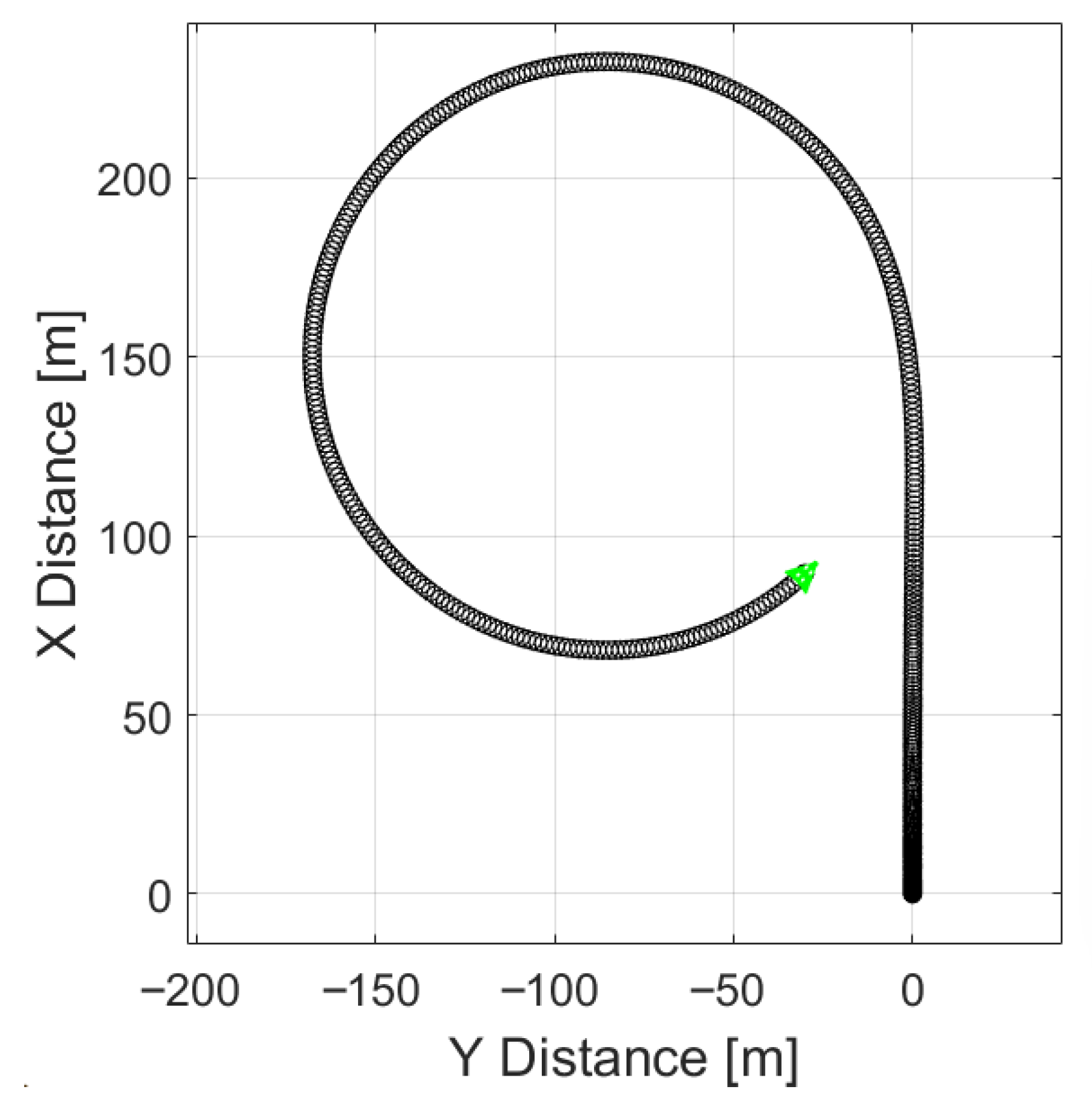
Section 2. The simulated vehicle speed was limited to the range of 40–50 km/h, the steering angle was set to 3.2°, and the road friction coefficient (μ) was set to 0.25. The coefficient of friction (μ) is a key measure of how slippery a surface is, representing the ratio of the frictional force to the normal force between two surfaces. A higher μ indicates greater grip, while a lower μ signifies a more slippery surface. In this case, a friction coefficient of 0.25 simulates a relatively slippery road surface, affecting both longitudinal and lateral slip during vehicle movement. Longitudinal slip occurs when the tire moves forward or backward relative to its direction of travel, influenced by braking or acceleration, while lateral slip happens during cornering. Both types of slip are governed by the friction between the tire and the road, where lower μ values lead to higher slip and reduced control, especially in slippery conditions. Prior to the first simulation with regenerative braking, a baseline simulation without regenerative braking was performed to verify vehicle stability under these specified parameters (
Figure 7a).
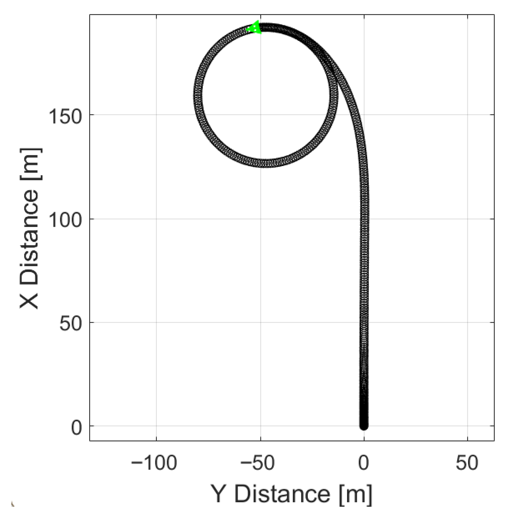
As long as the slip angle remained equal to zero, the vehicle followed the same trajectory as the orientation of the vehicle body, i.e., no skidding occurred and the vehicle remained stable. The same maneuver, when performed with regenerative braking applied at 35 s of the simulation, produced the results shown in
Figure 7b.
A distinct change in trajectory is observed when regenerative braking is applied. Additional insights can be obtained from the simulated vehicle’s ESP system. For the ESP system to distinguish between wheel slip and a rapid steering maneuver, a reference yaw rate must be calculated, representing the motion of a non-slipping vehicle during a given maneuver. In this simulation model, the ESP system applies the following equation:
where
r is the yaw rate,
v—vehicle speed,
R—turning radius,
L—vehicle’s wheelbase, and
δ—vehicle’s steering angle. The yaw rate calculated using this equation is compared with the sensor data in a real vehicle or with the simulated outputs of the vehicle body dynamics block in the model. The difference between these two values indicates whether the vehicle is experiencing excessive or insufficient yaw.
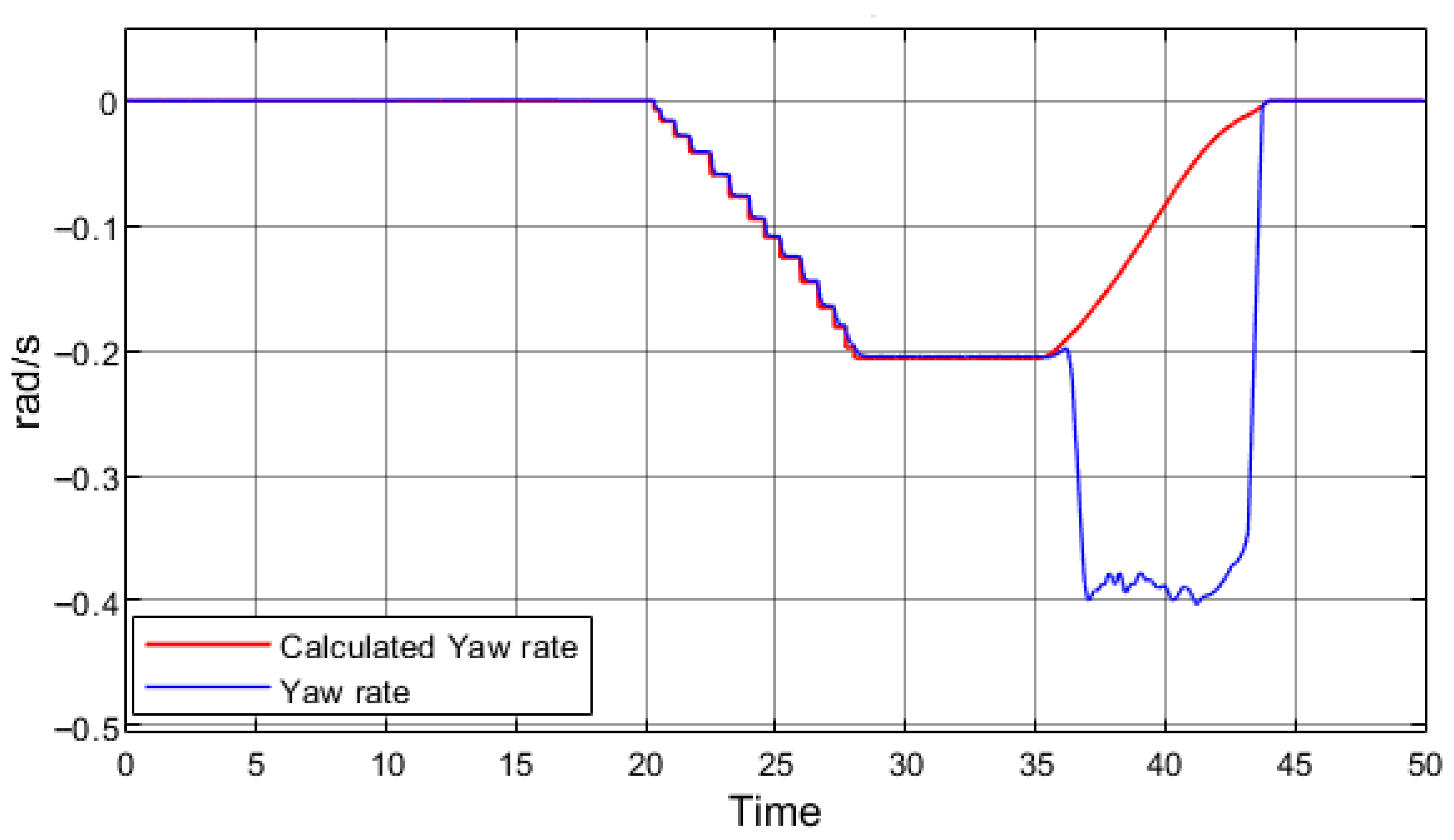
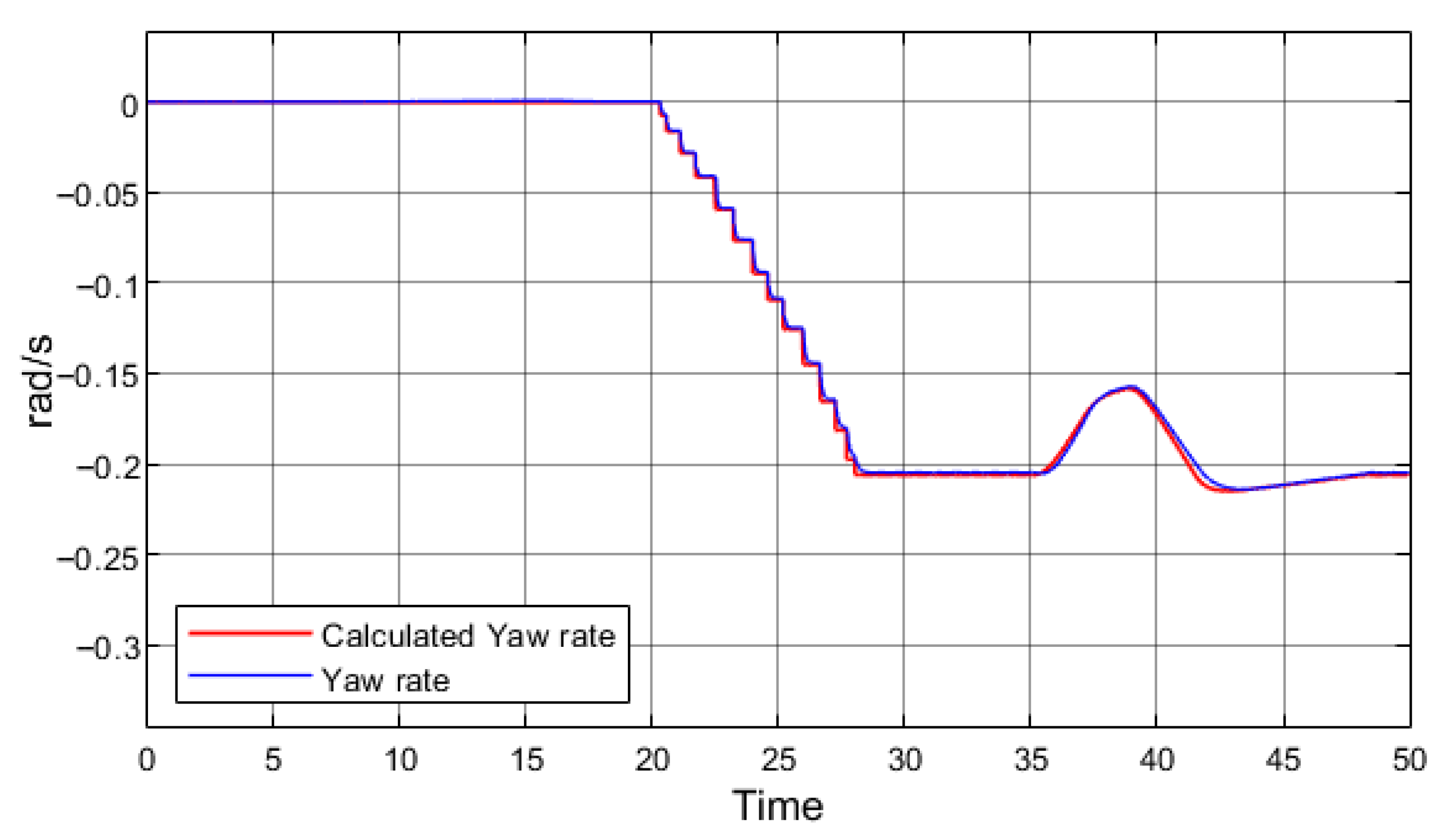
Figure 8 presents the yaw rate data obtained from the simulation with regenerative braking.
A discrepancy between the simulated yaw rate and the calculated reference value indicates that the vehicle is rotating about its vertical axis more rapidly than expected, i.e., experiencing excessive oversteer. Both graphs confirm that, once regenerative braking is initiated at 35 s, the simulated vehicle begins to lose stability. However, as in the field tests, complete loss of stability did not occur.
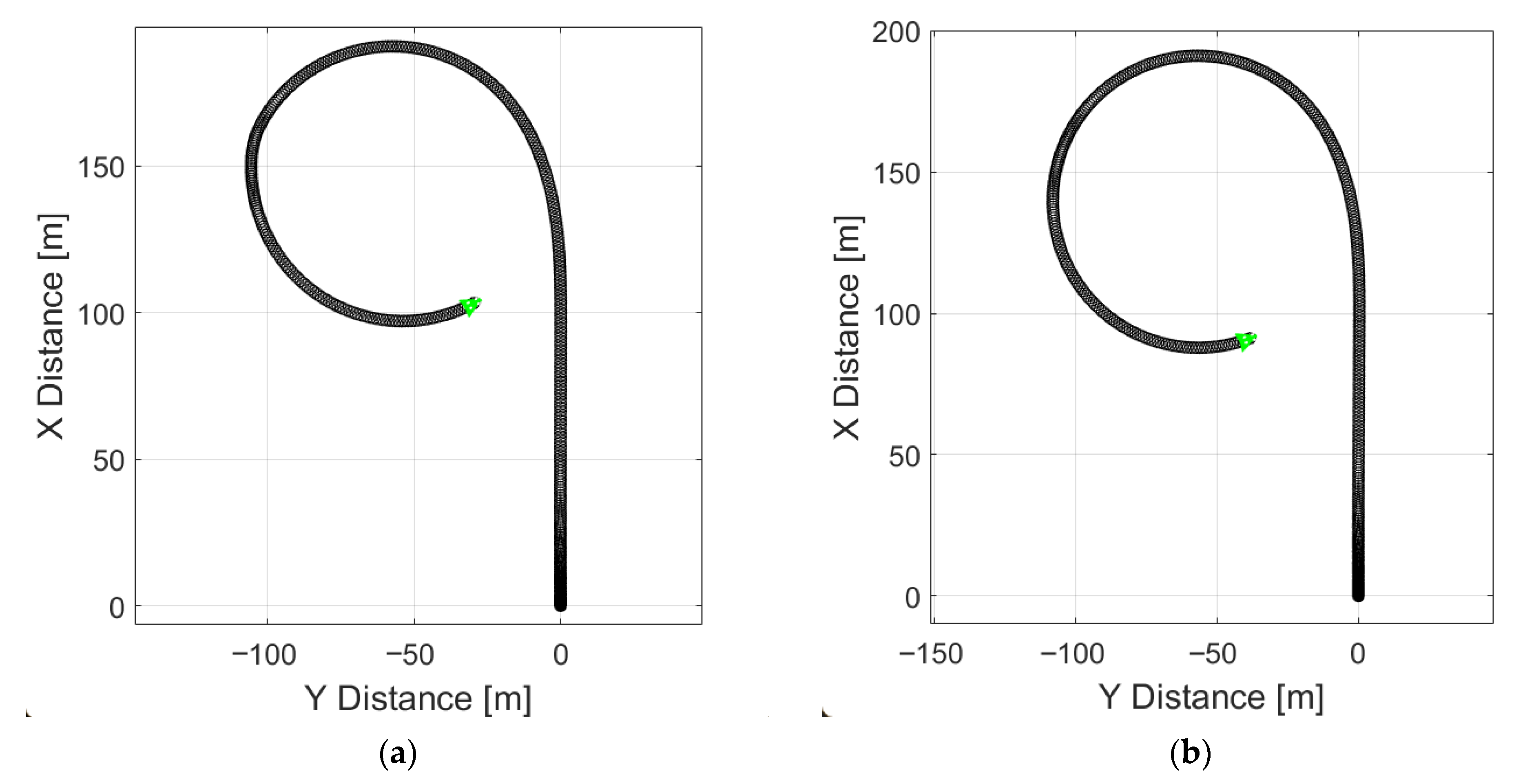
Figure 9a presents a simulation replicating a real test on a low-grip surface (
μ = 0.25), where regenerative braking begins at 35 s and is deactivated at 37 s. The resulting trajectory corresponds closely to the experimental results. Upon activation of regenerative braking, the vehicle exhibits excessive oversteer, triggering the ESP system, which is sufficient to prevent full loss of stability. A change in vehicle trajectory is also observed prior to the onset of regenerative braking. At approximately 23 s, the vehicle begins to skid and rotates around its vertical axis even though regenerative braking is initiated only at 35 s.
Figure 9b illustrates vehicle motion on a high-grip surface (
μ = 0.85). In this case, no signs of stability loss were indicated, as the trajectory indicates that the vehicle performs a uniform turn without experiencing either excessive or insufficient yaw.
These simulations therefore confirm that the developed model reproduces the results obtained in field tests under identical conditions. Subsequent simulations were conducted to examine how variations in vehicle speed and turn curvature affect electric vehicle stability.
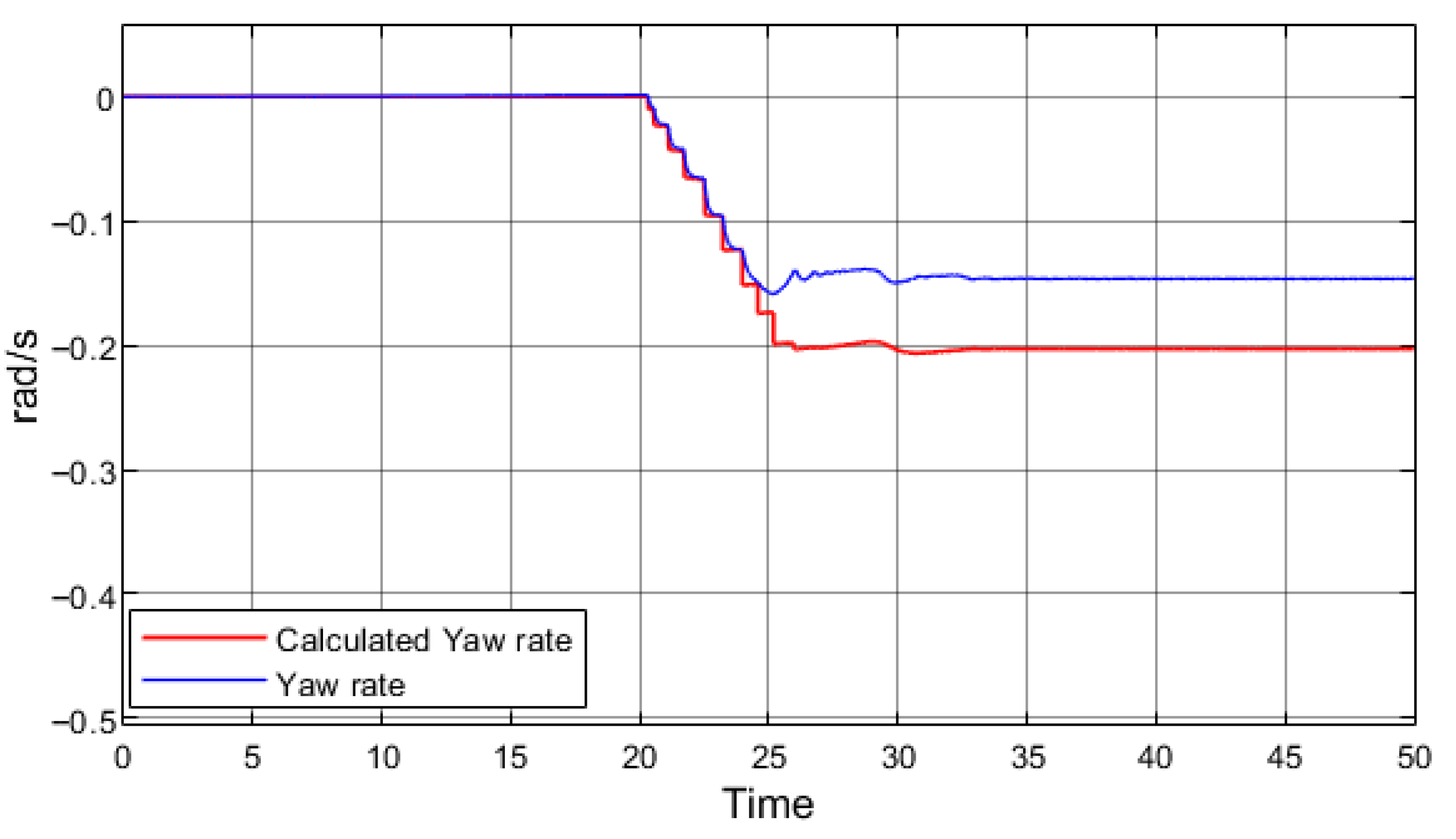
Further simulations were performed with modified parameters: maximum speed increased to 60 km/h with a steering angle of 2°, and maximum speed set to 40 km/h with a steering angle of 5°. These scenarios enable the investigation of conditions under which the simulated vehicles may completely lose stability during regenerative braking. In the subsequent simulations, the ESP system remained active. At 60 km/h with a 2° steering angle, the vehicle trajectory remained stable in cornering without regenerative braking (
Figure 10).
Simulating electric vehicle with maximum speed 40 km/h, steering angle 5° and without regenerative braking also keeps the vehicle stable through the turn as shown in
Figure 11.
The initial simulations that recreate experiments performed with real vehicles, as well as the vehicle field tests described in
Section 3, did not result in complete stability loss; in those cases, stability was only degraded. The simulations presented in this section demonstrate that under certain conditions, an electric vehicle cornering on a slippery surface—even with an active ESP system—may lose stability entirely, become uncontrollable, and spin out.
5. Results and Discussion
Based on experimental research, it was established that rear-wheel-drive (RWD) electric vehicles (EVs) experience reduced stability when driving on low-grip surfaces under regenerative braking.
Figure 3 and
Figure 4 clearly illustrate the exact moment of regenerative braking activation, at which point a distinct increase in yaw rate is observed. During testing, the vehicles did not experience complete loss of stability, as the Electronic Stability Program (ESP) system successfully prevented spin-out. These findings were consistent with results obtained from the simulation model. By applying the same technical parameters of the vehicles, road adhesion coefficient, and steering angle used in the experiments, the simulations produced results that aligned with field tests. In both cases, the vehicles exhibited partial stability loss, but the ESP system effectively prevented a complete spin-out. However, when simulating critical driving conditions, such as excessive speed in a turn or overly sharp steering with the ESP system active, vehicles still lost stability due to regenerative braking. This suggests that, in certain situations, the ESP system alone is insufficient to maintain vehicle stability.
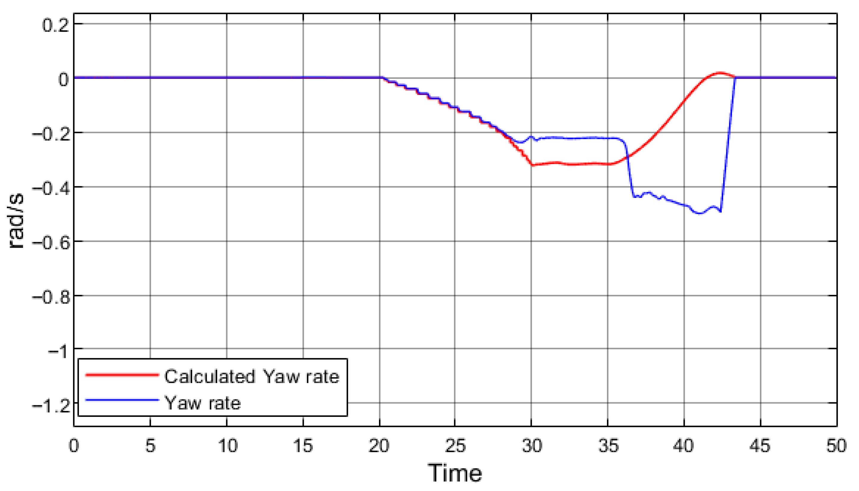
Figure 12 presents driving at higher speed in a corner without regenerative braking; the simulated vehicle did not lose stability, as indicated by the smoothly varying yaw angle. A slight deviation between the yaw rate signals shows that the vehicle experienced mild understeer, but overall stability was maintained.
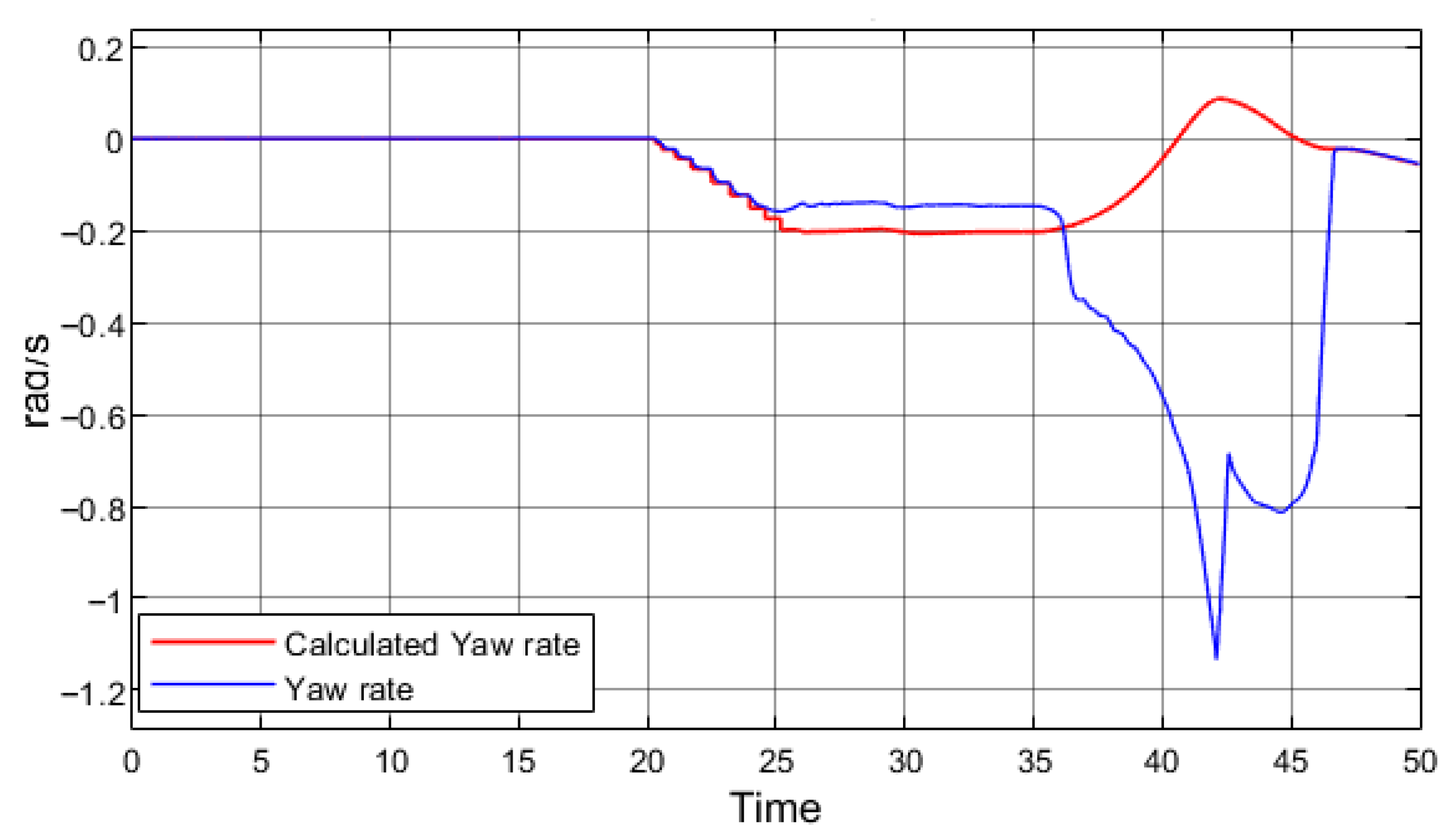
Figure 13 presents the same maneuver as in
Figure 12, but with regenerative braking applied.
The yaw rate signals clearly demonstrate that the vehicle completely lost stability and spun out. It is important to note that unlike in the previous simulations, the duration of regenerative braking was reduced from 5 s to 2 s. This result indicates that at higher speeds an electric vehicle can lose stability entirely, even when negotiating a smaller steering angle or when regenerative braking is applied for a shorter period.
When the speed is reduced to 40 km/h and the steering angle is increased from 2° to 5° (a sharper turn), regenerative braking can likewise cause vehicle instability and spin out (
Figure 14).
In summary, the analysis of the effects of speed and turn trajectory on electric vehicle stability during regenerative braking on a low-grip surface shows that in both examined cases, vehicle lost its stability. Consequently, to enhance both the safety of regenerative braking and the overall stability of EVs, additional systems that account for a broader range of external factors must be implemented.
Previous research, particularly the work by Hancock and Assadian (2006) [
12] in their study, has similarly highlighted the influence of regenerative braking on vehicle stability. They investigated the effect of regenerative braking on hybrid vehicles and concluded that regenerative braking could lead to compromised stability, especially during cornering, when the braking force is not uniformly distributed across the wheels. Their findings align with the results presented in this study, emphasizing that regenerative braking, while beneficial for energy recovery, poses challenges to vehicle control under low-traction conditions. Hancock and Assadian suggested that integrating advanced control strategies, such as coordinated braking systems that blend regenerative and friction braking more effectively, could mitigate these stability issues. These findings could be instrumental in improving road safety by informing the development of new control algorithms that better balance regenerative braking with the vehicle’s overall stability, particularly in critical driving scenarios.
In addition to these factors, there are always physical elements that play a role in stability issues. Poor wheel alignment and bad tires significantly affect a vehicle’s ability to maintain traction. These external factors, when combined with regenerative braking, can exacerbate stability problems. Therefore, improving the safety of regenerative braking and EV stability requires not only advanced braking control systems but also careful consideration of the vehicle’s physical condition.
Several solutions have been proposed to address these identified issues. The first is to reduce regenerative braking intensity under adverse weather conditions. All EVs, like conventional vehicles with internal combustion engines, are equipped with external temperature sensors as well as humidity or rain sensors. These sensors can provide information on whether precipitation has occurred, whether ambient temperatures have been below freezing, and whether ice formation is possible. Such information could also be obtained from advanced vehicle-to-infrastructure (V2I) systems. Based on these inputs, the vehicle could assess the probability of driving on a low-grip surface. If this probability is high, the vehicle could limit regenerative braking torque.
Figure 15 presents the results of a simulation in which regenerative braking torque was reduced to 300 Nm. For comparison, during field tests, Tesla Model 3 applied 535 Nm and the VW ID.3 applied 378 Nm.
By reducing regenerative braking by only 78 Nm (compared with the VW ID.3), vehicle stability under regenerative braking was fully preserved. In this case, regenerative braking was applied from 35 s to 37 s.
This approach, however, presents both advantages and disadvantages:
Advantages: Stability is maintained under regenerative braking even on low-grip surfaces, and the vehicle remains controllable in cornering maneuvers.
Disadvantages: Limiting regenerative braking reduces the amount of recovered energy, thereby decreasing EVs’ efficiency. Furthermore, drivers accustomed to the expected deceleration profile may experience discomfort, and sudden changes in deceleration dynamics could increase the risk of hazardous situations.
An alternative solution is the dynamic control of regenerative braking according to weather conditions. Similarly to the previous approach, the vehicle would rely on temperature, rain, and humidity sensors (or V2I inputs) to assess the probability of low-grip road surfaces. If slippery conditions are detected, regenerative braking would be applied progressively rather than at maximum torque immediately upon accelerator pedal release. Instead, the braking torque would be gradually increased, ensuring both maximum energy recovery and improved vehicle stability.
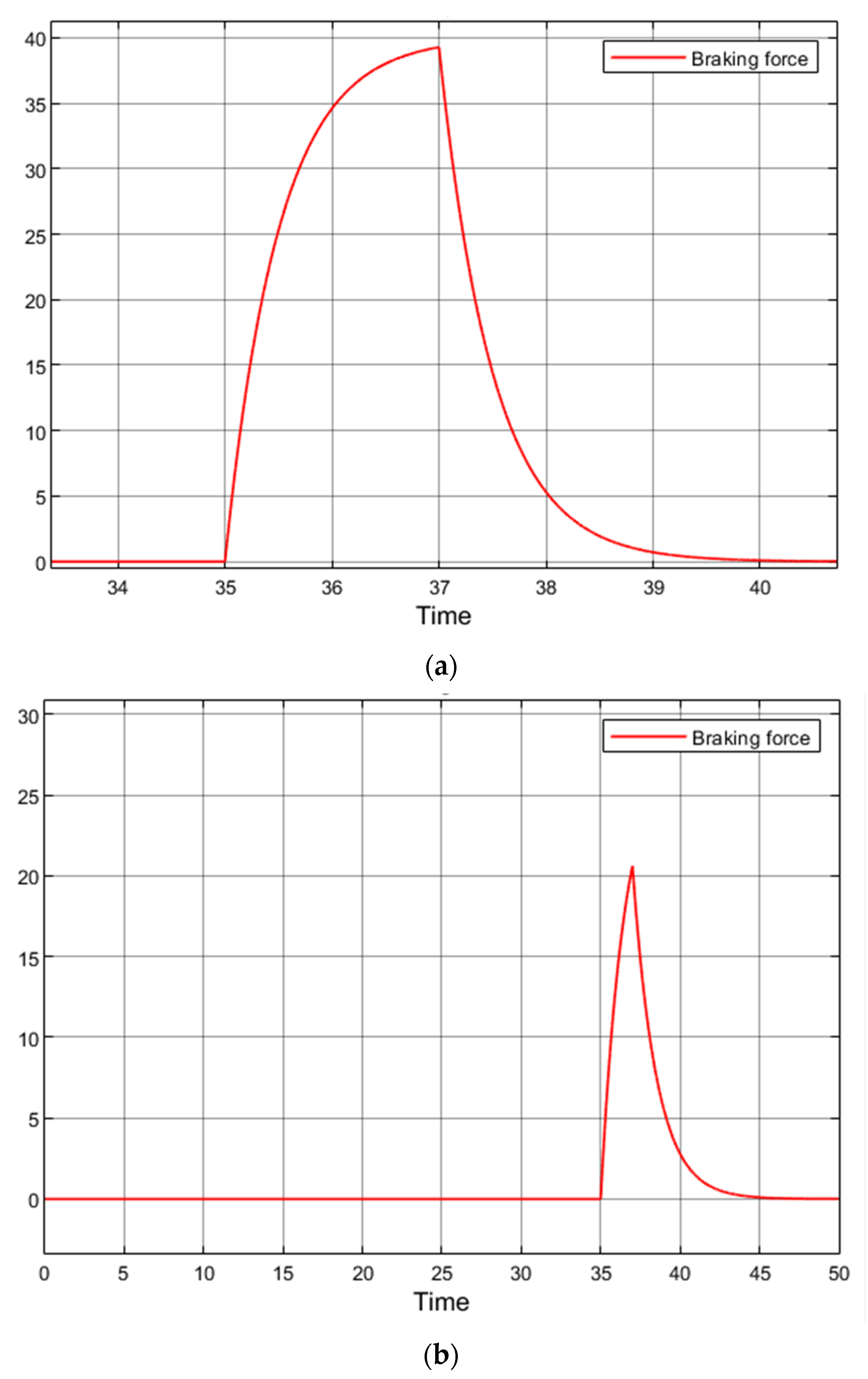
Figure 16a shows the regenerative braking torque command applied to the rear wheels of the simulation model, as used in the previous simulations.
When the rate of increase in the braking command signal is reduced, the electric vehicle maintains stability. However, within 2 s the signal only reaches 20% of the maximum braking torque limit, instead of the intended 40% (
Figure 16b). Consequently, the efficiency of regenerative braking is reduced.
By extending the duration of regenerative braking to 8 s, vehicle stability is preserved and the system reaches 37% of the maximum braking torque.
Figure 17 presents the braking torque profile corresponding to the 8 s regenerative braking interval.
Advantages: ensures vehicle stability under low-grip conditions; enables higher regenerative torque recovery compared to the 2 s case.
Disadvantages: reduced overall regenerative braking efficiency compared to full-capacity operation; extended braking duration may alter the expected deceleration response, potentially affecting driver comfort; less effective in scenarios requiring rapid deceleration.
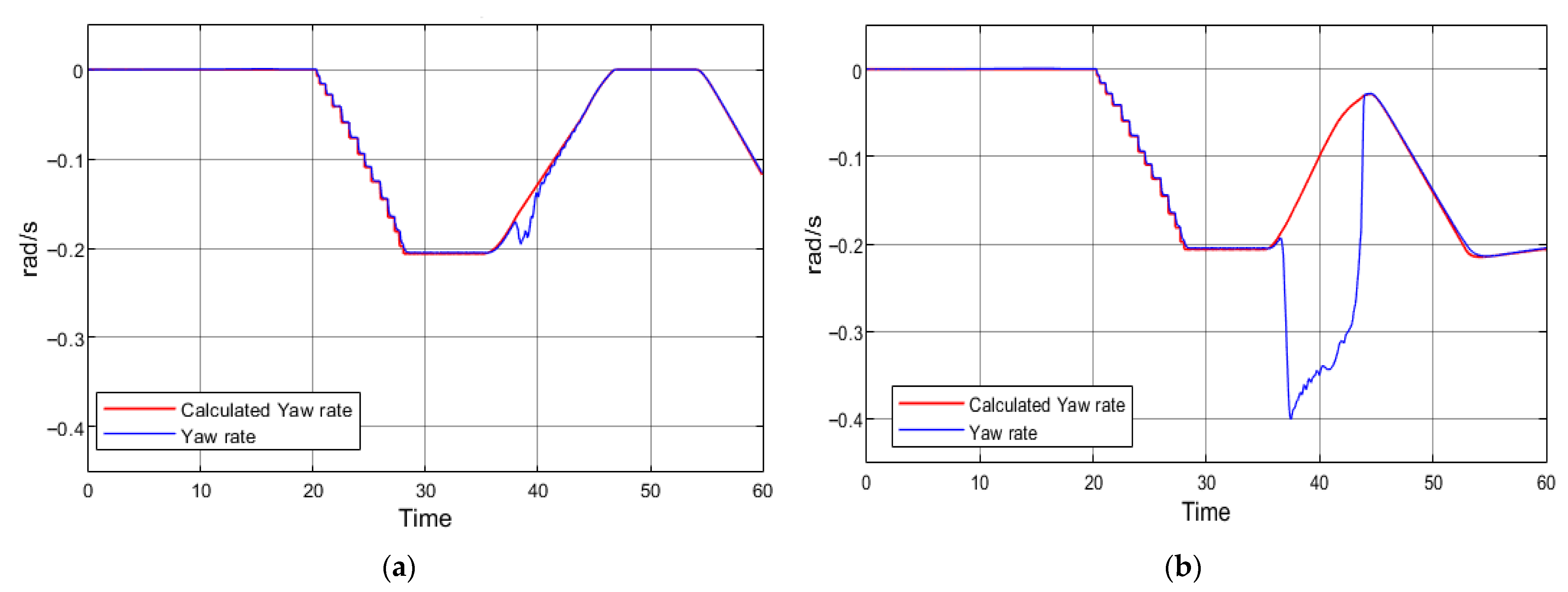
In
Figure 17a, it can be observed that the yaw rate signals coincide, except within the 37–40 s interval. During this period, regenerative braking is active, resulting in a minor deviation in the vehicle’s trajectory. However, after 40 s, the yaw rate values return to the nominal range. This deviation indicates only a slight reduction in stability. This control approach resembles the regenerative braking torque limitation strategy, but without directly restricting the maximum braking torque. If braking is applied for a sufficiently long duration, the regenerative torque can still reach its maximum value. For comparison,
Figure 17b illustrates the same maneuver without the gradual increase in regenerative braking torque.
The study “Adaptive Regenerative Braking Control in Severe Cornering for Guaranteeing the Vehicle Stability of Fuel Cell Hybrid Electric Vehicles” by Han et al. (2011) [
35] presents a similar but more intricate adaptive control strategy to maintain vehicle stability during aggressive cornering when regenerative braking is applied. The proposed system dynamically adjusts the regenerative braking force, enhancing the vehicle’s stability by preventing undesirable yaw moments that may lead to loss of control. While this research provides valuable insights into stability enhancement for fuel cell hybrid electric vehicles (FCHEVs), it primarily focuses on front–wheel–drive (FWD) configurations. In contrast, my study extends this concept to rear–wheel–drive (RWD) electric vehicles, which face unique stability challenges during cornering due to the rearward distribution of braking forces. RWD vehicles, particularly under regenerative braking conditions, are more prone to loss of stability, as the rear axle, which handles both propulsion and braking, can induce significant yaw moments. By focusing on RWD electric vehicles, my study contributes new knowledge by highlighting the specific challenges faced by these vehicles and exploring novel control strategies for maintaining stability. This extension to RWD vehicles addresses a critical gap in the existing literature and emphasizes the need for adaptive braking control systems that are tailored to the unique dynamics of RWD EVs.
Thus, in order to maintain stability during cornering on low-grip surfaces with regenerative braking, a dedicated regenerative braking control system is required. The simulation studies demonstrated that on dry asphalt no stability issues are observed; therefore, the proposed improvements are specifically relevant for low-grip surfaces. Two control strategies for regenerative braking were evaluated: torque limitation and dynamic control of torque build-up. Both methods enhance vehicle stability but differ in implementation complexity.
Regenerative braking torque limitations are as follows:
Advantages: simple implementation, can be applied to most EVs without significant modifications.
Disadvantages: reduces the overall efficiency of regenerative braking and may cause driver discomfort due to frequent changes in deceleration behavior.
Dynamic control of regenerative braking:
Advantages: maintains higher regenerative efficiency compared to torque limitation; smoother and more adaptive response.
Disadvantages: more complex to implement. To maximize efficiency, the system must operate at the adhesion–slip threshold, requiring the integration of ABS-like algorithms to estimate the road friction coefficient and dynamically adjust regenerative torque.
In this sense, regenerative braking could evolve into a new form of ABS, where braking force is generated by the electric motor rather than conventional hydraulics.
6. Conclusions
Regenerative braking enhances the energy efficiency of electric vehicles (EVs); however, it may adversely affect vehicle stability, particularly in corners or on slippery surfaces in rear-wheel-drive configurations. Current regenerative braking systems effectively recover energy, yet electronic stability programs (ESP) do not consistently mitigate the stability disturbances induced by these systems.
The stability of an EV during cornering is influenced by factors such as road surface friction, drive axle configuration, braking system characteristics, chassis dynamics, and active safety systems, including ABS and ESP. When regenerative braking is applied, additional factors begin to influence EVs stability, which have yet to be fully investigated.
Experimental research of rear-wheel-drive (RWD) EVs revealed that regenerative braking during cornering on low-grip surfaces results in a loss of stability. Increased oversteer was observed, indicating an inevitable reduction in stability, although no complete loss of control was recorded.
Analysis of the experimental data indicates that while ESP can significantly attenuate the destabilizing effects of regenerative braking, it does not entirely eliminate them. This suggests that even with active safety systems engaged, EVs remain susceptible to variations in road surface conditions during braking.
A simulation model developed for this study successfully replicated the experimental results, thus proving suitable for further analysis and critical scenario prediction. Simulations indicated that under certain extreme conditions, RWD EVs could experience a total loss of stability, including spinouts or uncontrollable trajectory deviations.
The proposed solution is to modulate the regenerative braking force in accordance with environmental sensor data (temperature, humidity, precipitation), thereby reducing the load on the rear axle under slippery conditions. However, it is important to recognize that varying braking intensity may negatively impact the driver’s perception and potentially lead to unexpected vehicle behavior in emergency situations.
This study makes an important contribution by combining real-world testing of production EVs with validated simulation modeling, thereby demonstrating that regenerative braking can still pose a stability concern under low-friction cornering conditions in rear-wheel-drive vehicles. The experimental results confirm that the issue is not merely theoretical, while the simulation highlights that relatively simple control strategies—such as adaptive modulation of regenerative braking or integration with advanced control algorithms—can mitigate stability loss. By bridging real-life testing and predictive simulation, the research underscores both the urgency and feasibility of improving regenerative braking strategies. Moreover, it emphasizes the need for continued investigation through more robust simulation approaches and extended real-world EV testing to ensure that future electric vehicles can achieve both maximum efficiency and uncompromised safety.
Future developments, such as the control of wheel hub motors or the use of electric motors as part of the ABS, present promising avenues for enhancing stability. Tesla’s patents reveal advanced traction control systems, although their application under challenging conditions remains insufficiently explored. Further advancements in control algorithms are required to ensure the safe and efficient operation of electric vehicles under a broad range of driving conditions.
