Article

Effect of Oblique Impact Angles on Fracture Patterns in Laminated Glass Plates Impacted by a 10 mm Steel Ball

Department of Architectural Engineering, Kyonggi University, Suwon 16227, Republic of Korea
Appl. Sci. 2025, 15(20), 10898; https://doi.org/10.3390/app152010898
Submission received: 22 September 2025 / Revised: 6 October 2025 / Accepted: 9 October 2025 / Published: 10 October 2025

Abstract

Featured Application

A database was established cataloguing the fracture modes of 5 mm thick glass plates impacted by 10 mm steel balls at various angles. The images of damage patterns were systematically analyzed in terms of cone cracks, perforated holes, and normalized kinetic energy.

Abstract

Many studies have examined normal impacts on glass, but data on oblique impacts are limited, and, in particular, there is very limited experimental data on oblique impacts at various angles under consistent experimental conditions. Therefore, this study investigated fracture patterns of 5 mm thick low-emissivity (low-e) glass impacted by a 10 mm steel ball at velocities of 40 to 50 m/s at various oblique impact angles from 0° to 80°. Results showed that fracture patterns varied clearly with impact angle. Truncated cone fractures occurred in all specimens at 0° to 60°, while three of six specimens did not fracture at 80° because the normal energy dropped to below damage limit energy. Damage parameters normalized by kinetic energy showed that Cmax/KE and Cmin/KE remained stable at 5.7–6.4 and 4.9–5.3 mm/J from 0° to 45°, but dropped sharply to 0.7 and 0.6 mm/J at 80°. The aspect ratio of cone cracks remained relatively constant (1.2–1.3) regardless of oblique impact angle, while the aspect ratio of perforated holes increased from 1.0 (0°) to 1.6 (60°) before decreasing at 80°. Steel ball size comparison confirmed that normalized damage patterns are not significantly affected by projectile size variations. Mechanism-based analysis revealed that cone cracks and perforated holes are governed by fundamentally different physical processes. Cone cracks form through axisymmetric stress fields following Hertzian contact theory, showing limited angular sensitivity (15.4% maximum eccentricity change). In contrast, perforated holes result from trajectory-dependent mechanical penetration, exhibiting extreme angular sensitivity with 338.9% eccentricity increase from 0° to 60°. This 22-fold difference demonstrates a dual damage mechanism framework that explains the pronounced angular dependence of hole geometry versus the relative stability of cone crack patterns. These findings provide essential data for forensic glass analysis and impact-resistant glazing design, while the dual mechanism concept offers new insights into angle-dependent fracture behavior of brittle materials.

1. Introduction

Glass windows are installed in the openings of buildings to perform key functions, such as providing observation of situations inside and outside the building, natural lighting, indoor heat loss prevention, and indoor air ventilation through opening and closing [1]. Through these various functions, glass windows play a crucial role in improving building energy efficiency and the comfort of occupants. Glass is now an essential material for modern life as its applications range from buildings to automobiles and furniture. Together with concrete as the structural backbone, glass serves as a critical envelope component in contemporary construction, providing both aesthetic and functional benefits while requiring careful consideration of impact resistance in design [2,3,4,5]. However, glass is easily damaged due to its brittleness, which may result from various causes, such as impact, thermal stress, internal defects, and improper installation. Many studies have examined and improved the impact resistance of glass panels against external impacts.
Kim and Choi [4] fabricated an air rifle-type steel ball impact test device, and performed a surface impact experiment using small-diameter steel balls on glass specimens prepared by coating a fabric-type glass fiber/epoxy composite onto soda glass plates. They reported that the brittle material coated with the composite effectively reduced surface fracture caused by the impact of small-diameter steel balls. Jeon et al. [5] designed and fabricated a compressed air-type impact test launching device that could launch a colliding body at a velocity of approximately 500 km/h, and conducted research on the impact characteristics of windshield (1000 mm × 700 mm) specimens used in urban and conventional railways according to the impact velocity using the launching device. Ha and An [6] conducted an experimental study on the crater and penetration depths, Hertzian cracks, radial cracks, wavy pattern cracks, and flower-shaped cracks caused by the penetration of a projectile into multilayered glass composed of seven soda lime glass layers with PC backing as a thin interlayer material. Choi et al. [7] conducted an experimental study in which a vehicle windshield (laminated glass) was impacted by a headform at various velocities.
Cai et al. [8] conducted research on impact fracture patterns using four types of laminated glass interlayers: polyvinyl butyral (PVB), polyurethane (PU), ethylene vinyl acetate (EVA), and SentryGlas Plus (SGP). At a velocity of 35 m/s, the laminated glass with PU and PVB interlayers exhibited higher impact resistance than the laminated glass with EVA and SGP interlayers. At velocities of 50 and 65 m/s, their impact resistance was even higher. Kim et al. [9] conducted research on the damage threshold velocity by launching 8 mm and 10 mm steel balls at 5 mm thick low-emissivity (low-e) glass. They reported that the damage threshold velocities of 8 mm and 10 mm steel balls for damaging 5 mm thick low-e glass are approximately 40 and 20 m/s, respectively.
Chen et al. [10] conducted research on parameters, such as the impact velocity, glass material properties, and intermediate layer thickness, with respect to the impact fracture characteristics of laminated glass using the combined finite-discrete element method. They reported that the optimal intermediate layer thickness ranges from 11% to 44% of the total thickness, and that laminated glass that uses multiple intermediate layers improves energy absorption and displacement reduction capabilities. Sharma et al. [11] analyzed the fracture patterns generated by impacting a 0.32-caliber bullet on fiberglass at various distances. As the firing distance increased from 4 to 11 m, the radial crack diameter increased from 1.29 to 1.42 inches due to the bullet taking more time to pass through the target at lower velocities, resulting in greater energy dissipation and larger fracture extension. Additionally, they observed that the number of radial fractures decreased from 9 at 4 m to 7 at 11 m due to reduced kinetic energy at greater distances. They reported that concentric fractures were combined with radial cracks for the crack patterns formed in the fiberglass due to its elastic properties. In addition, Waghmare N. [12], Harshey et al. [13], Tiwari et al. [14], and Abhyankar et al. [15] conducted research on the fracture patterns of glass caused by the bullets fired from rifles.
As for studies on impacts with angles rather than head-on collision, Cheong et al. [16] conducted research on the effects of both impact angle and impact velocity on the size distribution of glass fragments obtained from single particle impact experiments. They reported that elastic failure causes material to detach from the annular region at the contact area at low impact velocities and shallow impact angles, while inelastic failure prevails at high impact velocities and steep impact angles, leading to extensive fragmentation. Song et al. [17] investigated the breakdown patterns of silica glass under various impacts including thermal and projectile impact stress through forensic scientific analysis. They conducted experiments with projectiles at incident angles of 30° and 45° using slingshots with different ball bearing sizes (6 mm and 8 mm), and analyzed the resulting fracture patterns and perforation characteristics.
While extensive research has been conducted on glass impact resistance, systematic studies examining damage patterns across comprehensive oblique impact angles under consistent experimental conditions remain limited. Most existing studies focus on normal impacts or examine only specific angles, creating gaps in understanding angle-dependent fracture mechanisms. Therefore, this study systematically analyzes fracture patterns in 5 mm low-emissivity glass impacted by 10 mm steel balls across angles from 0° to 80°, building upon Kim et al. [9] to establish normalized damage parameters and identify critical angle thresholds for impact-resistant design applications.

2. Experimental Program

2.1. Test Specimens

In the experiment, low-e glass with a nominal thickness of 5 mm was impacted by a 10 mm steel ball at a velocity of 40 m/s or greater at various angles. Kim et al. [9] presented approximately 21 m/s as the limit velocity required to fracture 5 mm thick glass. Since the main purpose of this study is to analyze damage patterns according to the impact angle, the steel ball launch velocity was set to 40 m/s or above to occur significant damage on glass panel.
Nominal 10 mm steel balls designed for use in ball bearings were employed. To determine the actual diameter and weight, five balls were randomly selected and measured. The average measured diameter and weight were 10.03 mm and 4.16 g, respectively. The density calculated from the measured diameter and weight is 7.87 g/cm3.
Laminated low-e glass, which is widely used in shopping malls and residential buildings, was chosen for the experiments. Low-E glass is effective for energy saving by strongly reflecting solar radiation and indoor heating energy due to the thin silver coating applied onto conventional glass [18]. Laminated low-e glass is manufactured by bonding two single low-e glass panes separated by a gap of approximately 3 mm. In this study, single low-e glass panes were selected as the experimental specimens to analyze the fracture patterns under various impact angles. The Low-E glass used in the experiment was Super Low-E glass manufactured by LX Glass. The nominal single-layer silver coating thickness was 17 nm. According to KS L 2017 [19], the measured glass thickness was 4.8 mm, the moisture resistance was 0.3, and the emissivity was 0.111.
The size of the glass window was 800 × 800 mm, and each glass pane measured 650 × 650 mm. The glass experiment was carried out 7, 7, 7, 10, 7, and 7 times at impact angles of 0°, 15°, 30°, 45°, 60°, and 80°, respectively.

2.2. Test Setup

The test setup utilized the tension of rubber bands by simulating an actual slingshot (Figure 1). In this study, the steel ball velocity and the testing procedure were improved by upgrading the equipment used by Kim et al. [9]. The test setup consisted of five main parts. Part 1 was a rope pulley for pulling the electromagnet. Part 2 was a launching device that uses the electromagnet to pull the rope and apply tension to the rubber bands. The launching device integrated an electromagnet on one side, with a wire attached to a hook on the other. When the current flows, the electromagnet secures the wire hook; when the current is interrupted, the wire hook is released, and the wire is let loose. The launch velocity can be adjusted by controlling the rubber band draw length. Part 3 was a launching cart: a wire is connected at one end while a small cart, fastened with a rubber band, is connected at the other. After pulling the wire rope with the electromagnet launching device, pressing the launch button causes the small cart to propel the projectile. Part 4 was the velocity measurement unit, in which a commercially available laser velocity meter was installed. Part 5 was a glass fixing device. To replicate a real glass window, the frame was fabricated to enable installation. The size of the glass window frame was 800 × 800 mm. The frame’s width was approximately 75 mm, and its thickness 50 mm. Consequently, the glass size was 650 × 650 mm. To secure the glass window frame, four push toggle clamps were installed at the top and bottom, respectively. A large protective shield was also fabricated to prevent the scattering of glass fragments upon impact.

3. Experimental Results and Discussion

3.1. Damage Pattern

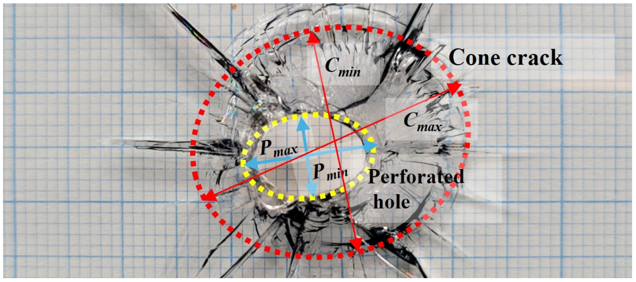
The main experimental results are presented in Table 1. Most of the glass damage exhibited the shape of a truncated cone, as shown in Figure 2. Here, Cmax and Cmin represent the maximum and minimum diameters of the cone crack, while Pmax and Pmin correspond to the maximum and minimum diameters of the perforated hole. The aspect ratio of the cone crack (ARC) and the aspect ratio of the perforated hole (ARP) are defined as the ratio of the maximum diameter to the minimum diameter for each damage type. Since impact velocities varied between tests, Cmax, Cmin, Pmax, and Pmin were normalized by the kinetic energy of the steel ball to enable an equal comparison of the results.
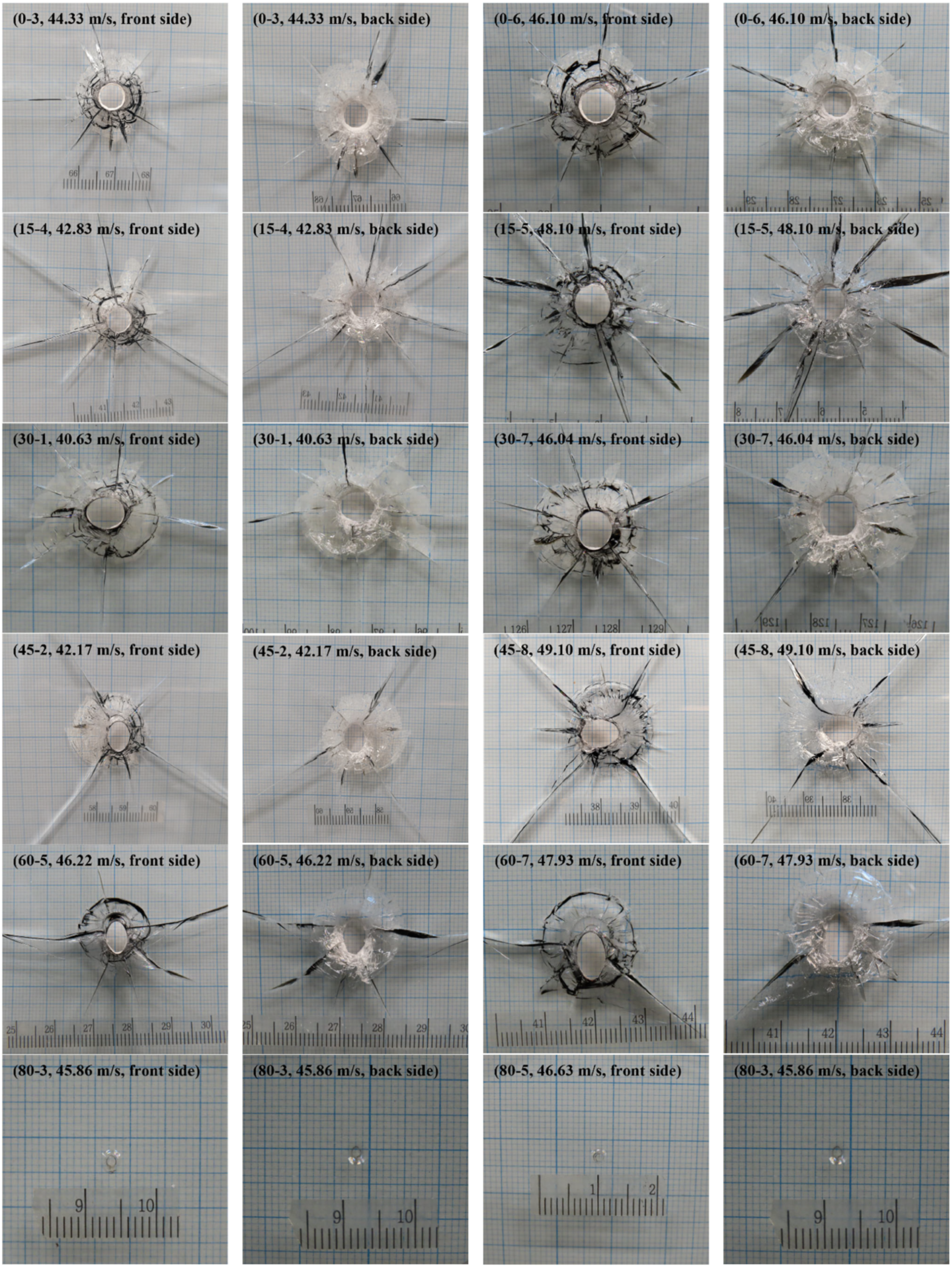
In addition, photographs of representative specimens obtained after the impact tests are shown in Figure 3.
In the experimental results, all specimens were fractured at every impact angle except for 80°. At 80°, three out of six specimens did not exhibit fracture; only impact marks were observed on the glass surfaces without failure.
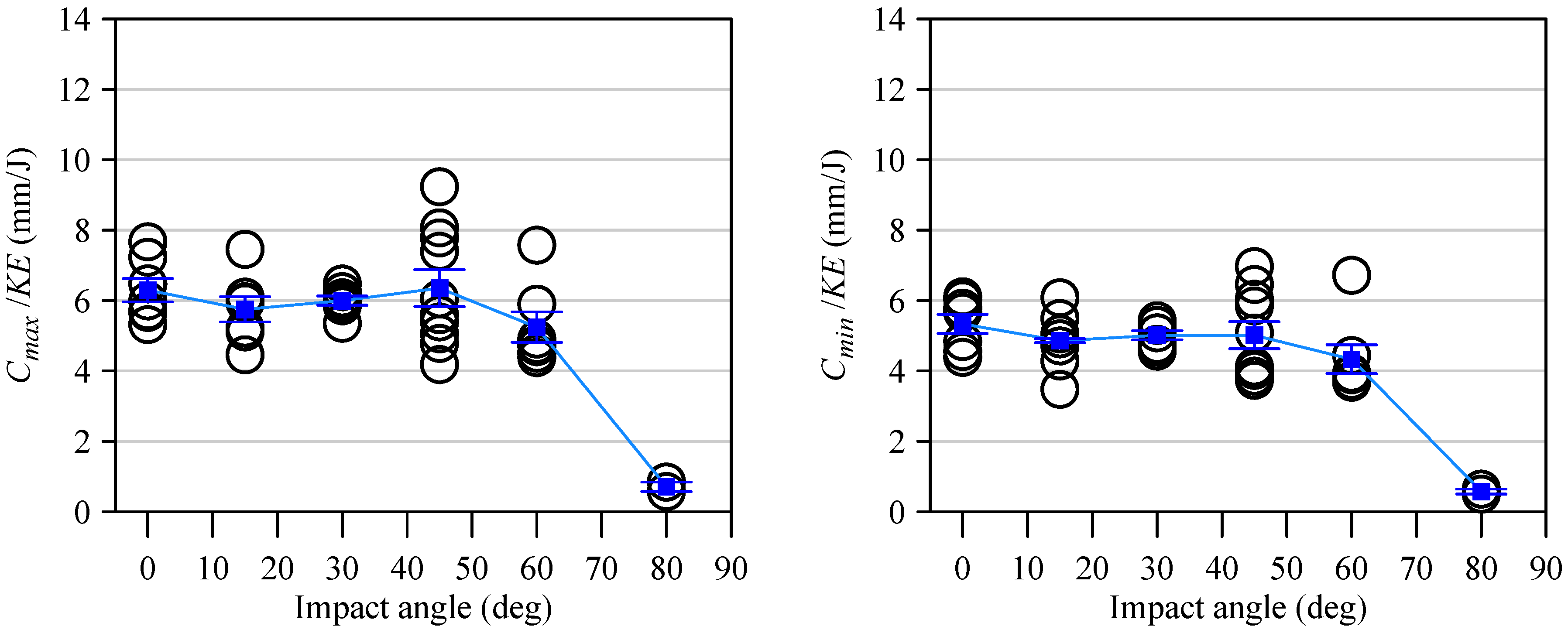
Figure 4 presents the Cmax/KE and Cmin/KE results as functions of the impact angle. At impact angles of 0°, 15°, 30°, and 45°, Cmax/KE exhibited similar values of 6.29, 5.75, 6.00, and 6.35 mm/J, respectively. At impact angles of 60° and 80°, the Cmax/KE values were 5.24 and 0.71 mm/J, respectively, which were significantly lower than at 45°. Cmin/KE also showed a tendency similar to that of Cmax/KE, with values ranging from 4.86 to 5.34 mm/J at impact angles between 0° and 45°, and decreasing sharply to 4.33 and 0.57 mm/J at 60° and 80°.
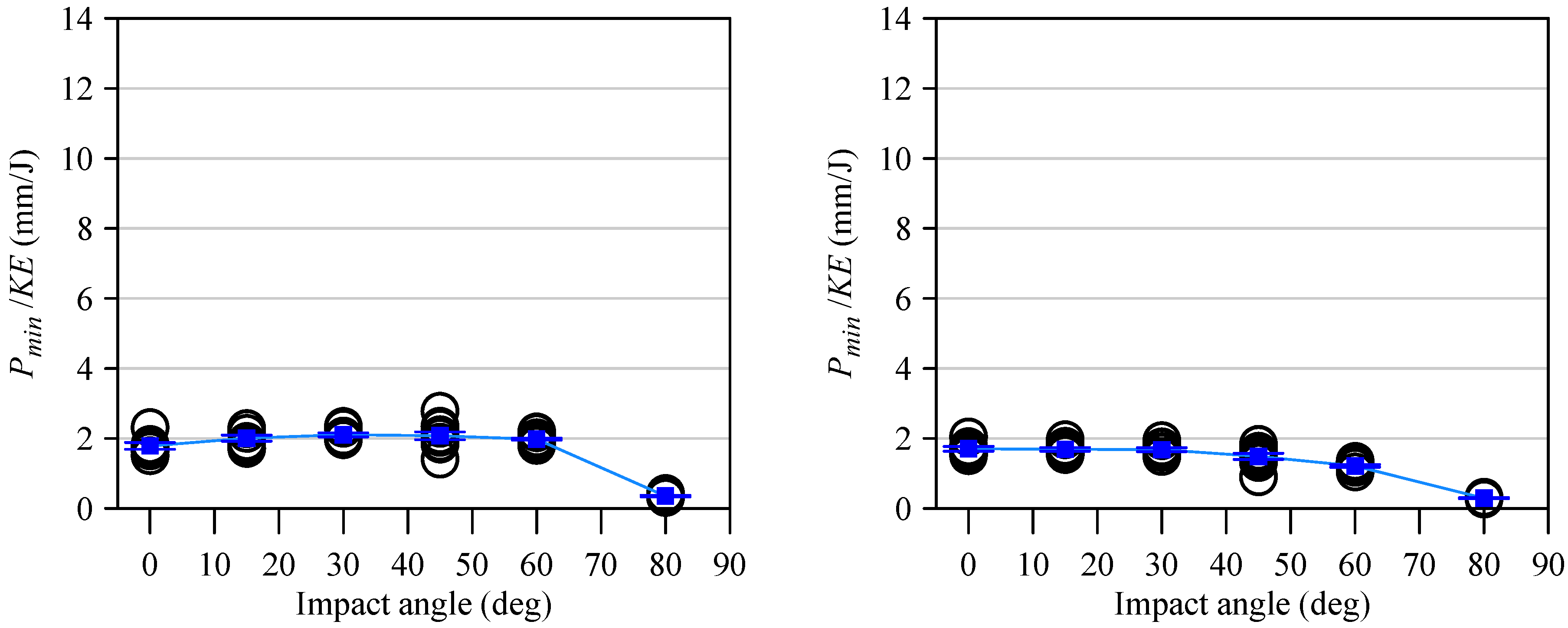
Figure 5 illustrates the Pmax/KE and Pmin/KE results according to the impact angle. The damage patterns for the perforated hole and cone crack as a function of impact angle displayed similar trends. Pmax/KE showed nearly constant values from 1.79 to 2.11 mm/J at impact angles from 0° to 60°, but dropped to 0.35 mm/J at 80°. Pmin/KE also exhibited values from 1.79 to 2.11 mm/J at impact angles from 0° to 60°, then decreased to 0.29 mm/J at 80°.
Analysis of Figure 4 and Figure 5 reveals two distinctions between the damage patterns of cone cracks and perforated holes. Firstly, the damage pattern for the cone crack remained consistent up to an impact angle of 45°, whereas that for the perforated hole remained consistent up to 60°. Secondly, there is a difference in the standard deviation: while the standard deviation of Cmax/KE and Cmin/KE ranged from 0.1 to 1.7, those of Pmax/KE and Pmin/KE ranged from 0.0 to 0.4. Comparison between Figure 4 and Figure 5 also indicates that the data in Figure 4 were more widely scattered, whereas the data in Figure 5 were concentrated around their mean values.
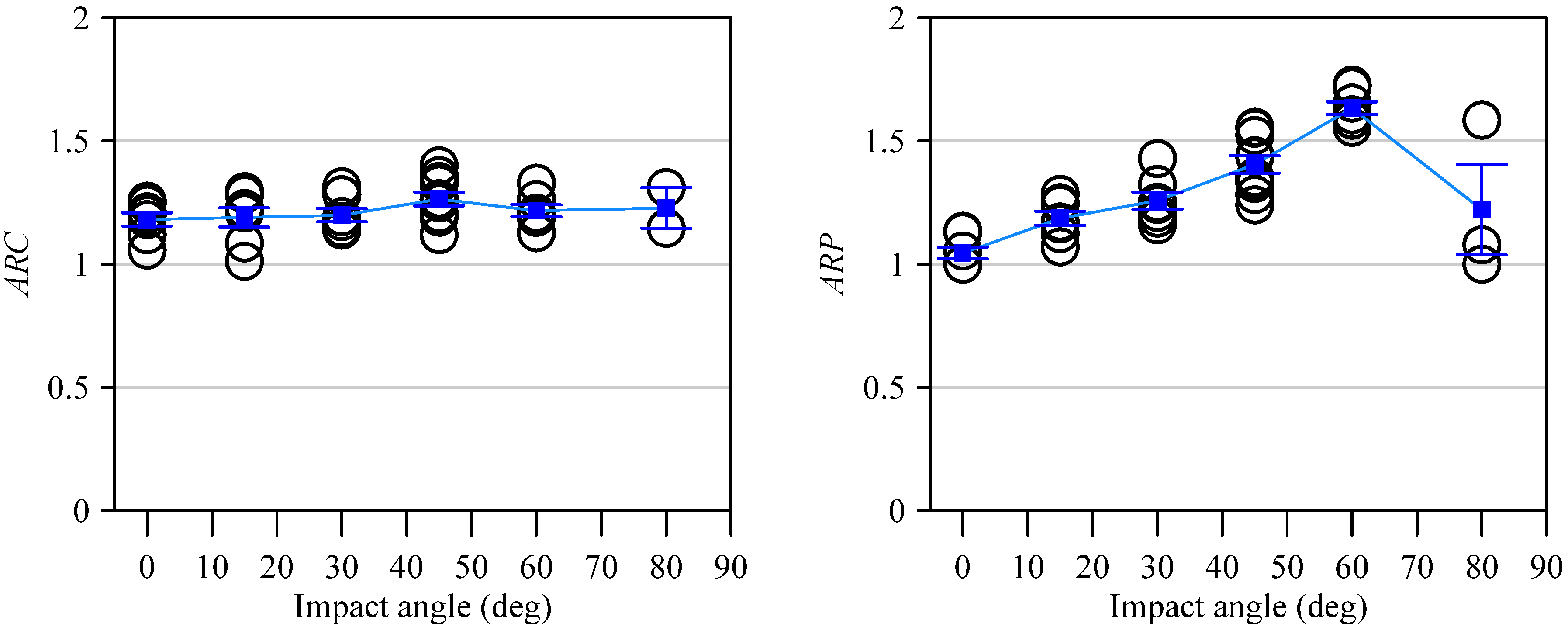
Figure 6 presents the ARP and ARC results as functions of the impact angle. The ARP and ARC values were 1.18 and 1.05, respectively, for a head-on collision. ARC ranged from 1.18 to 1.26 regardless of increasing impact angle. In contrast to the trend of ARC, ARP exhibited an increasing tendency, reaching a value of 1.63 at an impact angle of 60°, which was approximately 1.55 times greater than at 0°. At 80°, ARP significantly decreased to 1.22.

3.2. Eccentricity Analysis of Fracture Pattern

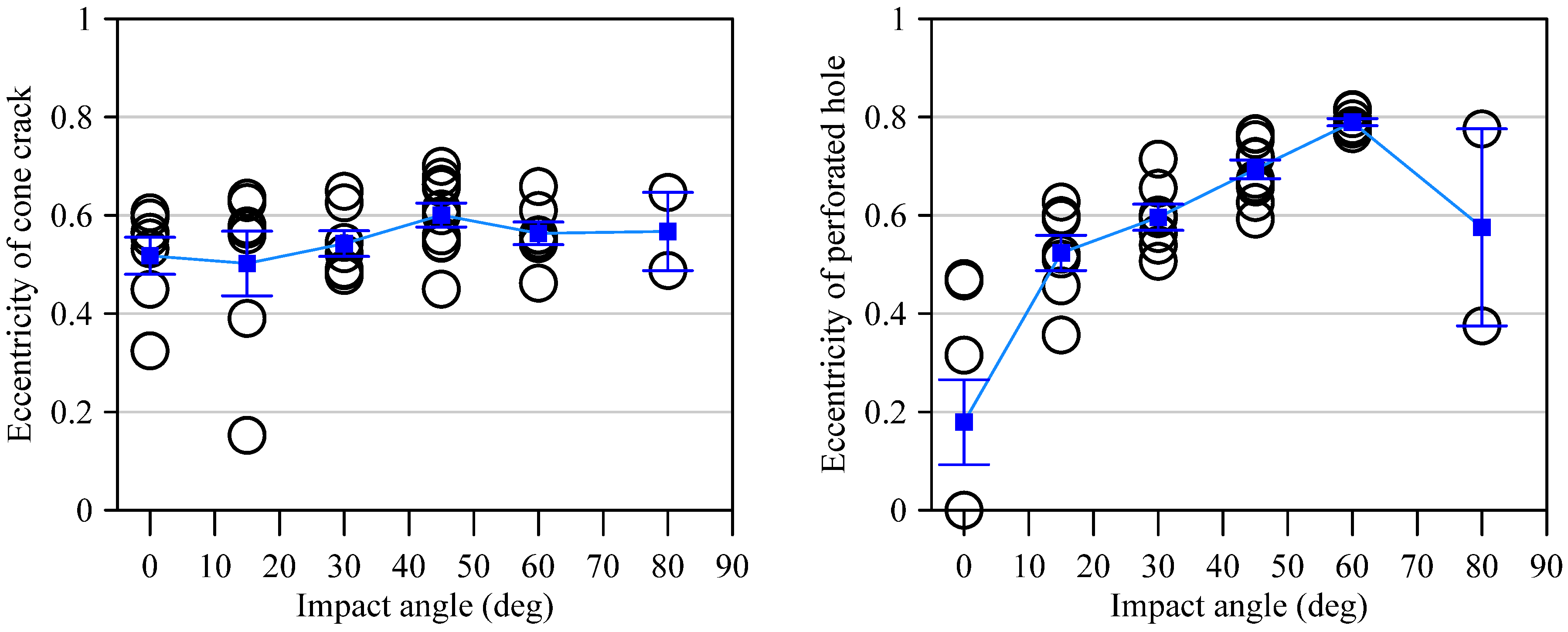
The aspect ratios of the cone cracks and the perforated holes were reanalyzed using eccentricity. The eccentricity of both cone cracks and perforated holes was calculated using the formula e = √(1 − (minor axis/major axis)2) to quantify the degree of asymmetry in the damage patterns. For cone cracks, the eccentricity gradually increased from 0.52 at an impact angle of 0° to 0.60 at 45°, followed by a slight decrease to 0.56 at 60° (Figure 7). In contrast, the perforated holes exhibited more pronounced angular sensitivity, with eccentricity increasing significantly from 0.18 at 0° to 0.79 at 60°. These experimental results suggest that while the cone crack patterns are relatively insensitive to the impact angle, the geometry of the perforated hole is significantly influenced by the impact angle.

3.3. Limit Impact Angle

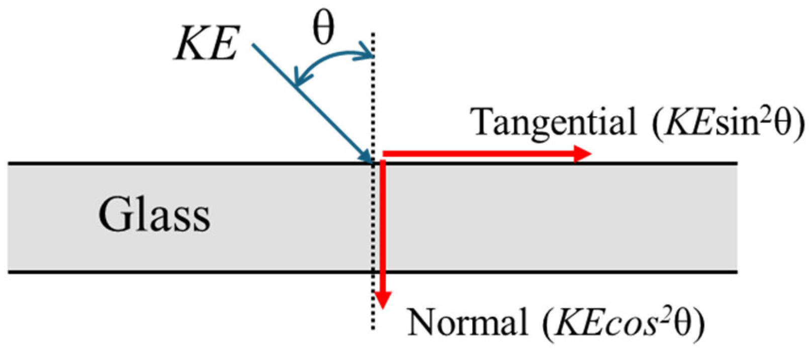
It appears that the impact mechanism transitions from direct impact energy to glancing impact energy at 80°. In the case of oblique impact, the impact energy is resolved into a normal component (En = KEcos2θ) and a tangential component (Et = KEsin2θ) (Figure 8). At an angle of 80°, it is considered that the critical impact energy required for brittle fracture of glass could not be reached because the normal component decreased sharply to 0.03KE. On the other hand, the tangential component (0.97KE) nearly represented the total impact energy, resulting in slippage of the steel ball along the glass surface.
According to Kim et al. [9], approximately 21 m/s was identified as the minimum velocity at which a 10 mm steel ball caused damage to 5 mm thick glass (damage occurred with an approximately 20% probability at launch velocities of 15 to 20 m/s). The kinetic energy of a 10 mm steel ball at an impact velocity of 20 m/s is 0.83 J. The velocity of the steel ball launched at 80° in this study ranged from 42.3 to 46.9 m/s. The normal component of impact energy at this angle ranged from approximately 0.112 to 0.137 J, normal impact energy was not sufficient to cause damage to the glass.

3.4. Differential Angular Sensitivity of Cone Cracks and Perforated Holes

The results showed a clear difference in angular sensitivity between cone cracks and perforated holes. While the eccentricity of cone cracks increased only 15.4% from 0.52 (0°) to 0.60 (45°), the eccentricity of perforated holes surged by 338.9% from 0.18 (0°) to 0.79 (60°). This 22-fold difference comes from different formation mechanisms.
Cone cracks form through a stress-field-dominated process according to Hertzian contact theory [20]. Following the Hertzian fracture theory of Frank and Lawn [21], when a projectile with contact pressure distribution P(r) = P0√[1 − (r/a)2] contacts the glass surface, the maximum tensile stress σₜ = (1 − 2ν)P0/3 is generated around the contact periphery [22]. Cone cracks initiate when σₜ exceeds the material strength. In these equations, ν is Poisson’s ratio, P0 is the maximum contact pressure, r is the radial distance from contact center, and a is the contact radius. Due to the symmetric stress distribution, the basic symmetry is maintained even with changes in impact angle, and the normal stress component plays a dominant role, resulting in limited angular dependence. The contact force from the steel ball distributes circularly throughout the glass, maintaining the axisymmetric nature of the stress field regardless of whether the impact is normal or oblique. Consequently, cone crack morphology remains nearly circular despite variations in impact angle.
In contrast, perforated holes form through a trajectory-dependent process involving direct mechanical penetration by the steel ball. The hole geometry is determined by the actual trajectory of the ball, becoming increasingly elongated and asymmetric as the impact angle increases. At oblique angles, the penetration path deforms into an elliptical shape, and the effective contact area increases proportionally to 1/cos(θ). The tangential energy component directly contributes to the asymmetric expansion of holes, particularly evident at 60° where the tangential energy (KE × sin2(60°) = 0.75KE) reaches three times the normal energy (KEcos2(60°) = 0.25KE), causing extreme morphological changes.
The 50% complete penetration failure rate observed at 80° supports this trajectory-dependent characteristic. When the normal energy comprises only 3% of the total energy, the mechanical penetration force required for hole formation becomes insufficient, resulting in probabilistic fracture behavior.

3.5. Comparison of Tests Results with 8 and 10 mm Steel Balls

Table 2 summarizes the experimental results for the damage patterns in glass impacted by an 8 mm steel ball at impact angles from 0° to 80° as reported by our research team’s previous study [23], alongside the results from the 10 mm steel ball tests in this study. When comparing the tendencies between the 8 mm and 10 mm experimental results, Cmax/KE, Cmin/KE, Pmax/KE, Pmin/KE, and ARP all exhibited similar trends. This indicates that the steel ball size does not have a significant effect on the overall tendency of the damage patterns.

4. Conclusions

In this study, the fracture patterns of 5 mm thick low-emissivity (low-E) glass impacted by a 10 mm steel ball at velocities of 40 m/s or higher and various angles (0°, 15°, 30°, 45°, 60°, and 80°) were analyzed. The experimental results revealed that the damage patterns of the glass varied with impact angle. The following conclusions were derived from the results:
  • The Cmax/KE and Cmin/KE values remained stable at 5.7–6.4 mm/J and 4.9–5.3 mm/J for angles from 0° to 45°, but dropped significantly to 0.7 and 0.6 mm/J at 80°. This change occurs because the normal impact energy component decreases from 0.5KE at 60° to only 0.03KE at 80°, showing that normal energy dominates the overall damage size.
  • Cone crack eccentricity increased only 15.4% maximum, while perforated hole eccentricity increased dramatically by 338.9% from 0.18 (0°) to 0.79 (60°). This 22-fold difference comes from different formation processes: cone cracks form through stress fields (following Hertzian contact theory), while perforated holes form through direct mechanical penetration that depends on the ball’s trajectory.
  • A critical angle exists around 80° where only 50% of specimens achieved complete penetration because the normal energy (0.11–0.14 J) falls below the threshold needed for glass fracture (~0.8 J). Most energy (97%) goes into the tangential direction, causing the ball to deflect rather than penetrate.
  • Comparisons between 8 mm and 10 mm steel balls showed similar trends in normalized parameters (Cmax/KE, Pmax/KE, aspect ratios), confirming that energy-based normalization works well for different projectile sizes in impact-resistant design.
  • This work was limited to 5 mm thickness single-pane low-E glass with specific impact velocities (40–50 m/s) and 10 mm ball size. Future studies should investigate: (1) laminated glass with different interlayer materials, (2) various glass thicknesses and types, (3) lower or higher velocity impacts, (4) three-dimensional damage modeling, and (5) predictive models based on the dual damage mechanism identified in this study for better impact-resistant glazing design.
These results provide essential data for forensic glass analysis and establish normalized damage parameters for impact-resistant glazing design. The dual damage mechanism concept offers new understanding of how brittle materials fracture at different impact angles.

Funding

This work was supported by Kyonggi University Research Grant 2023 (2023-011).

Institutional Review Board Statement

Not applicable.

Informed Consent Statement

Not applicable.

Data Availability Statement

The original contributions presented in the study are included in the article and further inquiries can be directed to the corresponding author.

Conflicts of Interest

The author declares no conflicts of interest.

References

  1. Korea Flat Glass Window Association. Changho Story—Dictionary Definition. 2018. Available online: http://www.kfgwa.or.kr/fittings-story/fittings-overview (accessed on 31 December 2024). (In Korean).
  2. Parhi, S.K.; Patro, S.K. Data-driven prediction and intelligent optimization of strength, porosity and cost of concrete with supplementary cementitious materials. J. Struct. Integr. Maint. 2025, 10, 2567084. [Google Scholar] [CrossRef]
  3. Regalla, S.; Kumar, N.S. Experimental investigations on performance efficiency characteristics of ultra-high-performance concrete (UHPC) with enhanced sustainable mineral admixtures. J. Struct. Integr. Maint. 2025, 10, 2538978. [Google Scholar] [CrossRef]
  4. Kim, H.G.; Choi, N.S. Surface fracture response of glass eabric/epoxy lamina-bonded glass plates to impact with small-diameter steel ball. Compos. Res. 2000, 13, 75–82. (In Korean) [Google Scholar]
  5. Jeon, H.K.; Park, C.K.; Seo, J.W.; Jeon, C.S. A Study on impact testing of a rolling-stock windscreen. J. Korean Soc. Radiol. 2013, 16, 365–371. (In Korean) [Google Scholar] [CrossRef]
  6. Ha, Y.D.; An, T.S. Peridynamic Impact fracture analysis of multilayered glass with nonlocal Ghost interlayer model. J. Comput. Struct. Eng. Inst. Korea 2018, 31, 373–380. (In Korean) [Google Scholar] [CrossRef]
  7. Choi, J.H.; Oh, W.T.; Kim, J.H.; Park, J.C. Experimental Study and Finite Element Analysis about Vehicle Laminated Glass Subject to Headform Impact. Korean Soc. Automot. Eng. 2017, 25, 374–379. (In Korean) [Google Scholar] [CrossRef]
  8. Cai, L.; Zhang, Y.; Wei, X.; Shi, J.; Zhang, Y.; Zhang, Y.; Wang, X. Study on the effect of different sandwich materials on the impact resistance of laminated glass. Constr. Build. Mater. 2022, 360, 129603. [Google Scholar] [CrossRef]
  9. Kim, S.; Mun, J.H.; Park, S.; Choi, C.; Hong, S. Damage Limit Velocity and Fracture Patterns in Single Glass Plates Impacted by Steel Balls of Varying Diameters. Appl. Sci. 2025, 15, 386. [Google Scholar] [CrossRef]
  10. Chen, X.; Chen, X.; Chan, A.H.C.; Cheng, Y. Parametric analyses on the impact fracture of laminated glass using the combined finite-discrete element method. Compos. Struct. 2022, 297, 115914. [Google Scholar] [CrossRef]
  11. Sharma, B.K.; Shukla, V.K.; Rath, A.; Philip, S.A. Effect of 0.32 Caliber Bullets on Fiberglass at Various Firing Distances and Determination of Range of Firing from the Fracture Patterns on Fiberglass. Int. J. Innov. Technol. Explor. Eng. 2019, 8, 2160–2166. [Google Scholar] [CrossRef]
  12. Waghmare, N.P. Distinctive Impact Pattern of AK 47/56 Projectile on Glass Fracture. J. Forensic Sci. Crim. Investig. 2018, 8, 555746. [Google Scholar] [CrossRef]
  13. Harshey, A.; Srivastava, A.; Yaday, V.K.; Nigam, K.; Kumar, A.; Das, T. Analysis of glass fracture pattern made by.177″ (4.5 mm) Caliber air rifle. Egypt. J. Forensic Sci. 2017, 7, 20. [Google Scholar] [CrossRef]
  14. Tiwari, N.; Harshey, A.; Das, T.; Abhyankar, S.; Yadav, V.K.; Nigam, K.; Anand, V.R.; Srivastava, A. Evidential significance of multiple fracture patterns on the glass in forensic ballistics. Egypt. J. Forensic Sci. 2019, 9, 22. [Google Scholar] [CrossRef]
  15. Abhyankar, S.; Srivastava, A.; Yadav, V.K.; Nigam, K.; Harshey, A. Glass Fractures Made from Different Pellet Shapes—APreliminary Stduy. J. Forensic Sci. Crim. Investig. 2018, 8, 555739. [Google Scholar] [CrossRef]
  16. Cheong, Y.S.; Salman, A.D.; Hounslow, M.J. Effect of impact angle and velocity on the fragment size distribution of glass spheres. Powder Technol. 2003, 138, 189–200. [Google Scholar] [CrossRef]
  17. Song, J.Y.; Sa, S.H.; Nam, J.W.; Kim, D.H.; Choi, Y.W.; Kim, J.P.; Goh, J.M.; Park, N.K. Forensic scientific analysis for glass breakdown patterns. J. Korean Soc. Saf. 2012, 27, 28–35. (In Korean) [Google Scholar]
  18. Bocchese, F.; Brown, I.; Cornil, D.; Moskovkin, P.; Muller, J.; Kenny, S.D.; Smith, R.; Lucas, S. Low-E glass improvement by the understanding and control of the Ag growth. Appl. Surf. Sci. 2003, 611, 155600. [Google Scholar] [CrossRef]
  19. KS L 2017; Low Emissivity Glass. Korean Standards and Certification: Seoul, Republic of Korea, 2018; p. 6. (In Korean)
  20. Hertz, H. Über die Berührung fester elastischer Körper. J. Reine Angew. Math. 1881, 92, 156–171. [Google Scholar]
  21. Frank, F.C.; Lawn, B.R. On the theory of Hertzian fracture. Proc. R. Soc. London Ser. A 1967, 299, 291–306. [Google Scholar]
  22. Chen, S.Y.; Farris, T.N.; Chandrasekar, S. Contact mechanics of Hertzian cone cracking. Int. J. Solids Struct. 1995, 32, 329–340. [Google Scholar] [CrossRef]
  23. Lee, K.-Y.; Kim, S.; Park, S.; Choi, C. Experimental Study on Damage Patterns of Glass Pane Subjected to Low-Velocity Impact Loads. Protect. Facil. 2025, 2, 12–19. [Google Scholar] [CrossRef]
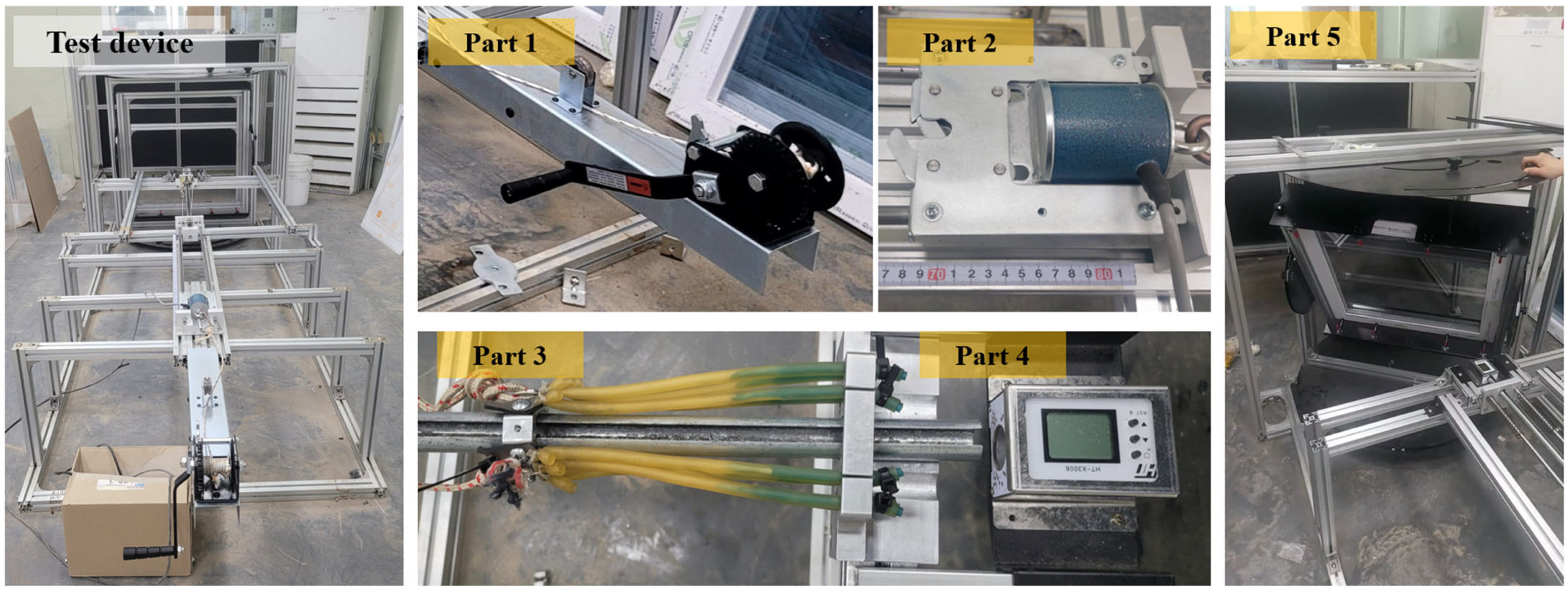
Figure 1. Glass impact test devices.
Applsci 15 10898 g001
Figure 2. Cone crack and perforated hole of damage.
Applsci 15 10898 g002
Figure 3. Selected test specimens.
Applsci 15 10898 g003
Figure 4. Cone crack normalized by kinetic energy.
Applsci 15 10898 g004
Figure 5. Perforated hole normalized by kinetic energy.
Applsci 15 10898 g005
Figure 6. Aspect ratio of cone crack and perforated hole.
Applsci 15 10898 g006
Figure 7. Eccentricity of cone crack and perforated hole.
Applsci 15 10898 g007
Figure 8. Kinetic energy decomposition in oblique impact.
Applsci 15 10898 g008
Table 1. Results of impact tests.

No.
Angle
(°)
Velocity
(m/s)
Cone CrackPerforated HoleNormalized Cone CrackNomalized Perforated HoleARCARP
Cmax
(mm)
Cmin
(mm)
Pmax
(mm)
Pmin
(mm)
Cmax/KE
(mm/J)
Cmin/KE
(mm/J)
Pmax/KE
(mm/J)
Pmin/KE
(mm/J)
0-1040.7924.9020.737.967.047.236.022.312.041.201.13
0-2043.9023.8922.606.706.705.995.671.681.681.061.00
0-3044.3321.6317.847.447.065.324.391.831.741.211.05
0-4045.2027.3824.466.386.386.475.781.511.511.121.00
0-5045.9324.9321.117.716.805.714.831.771.561.181.13
0-6046.1024.9120.037.257.255.664.551.651.651.241.00
0-7047.5135.8428.538.258.257.676.111.771.771.261.00
Average44.826.222.27.47.16.35.31.81.71.21.0
STDEV2.14.63.50.70.60.90.70.30.20.10.1
15-11541.2718.0217.817.576.065.115.052.151.721.011.25
15-21541.4321.1919.518.106.315.965.492.281.781.091.28
15-31541.9727.1822.178.337.167.456.082.281.961.231.16
15-41542.8322.5318.667.246.185.934.911.911.631.211.17
15-51548.1025.0020.519.177.385.224.281.911.541.221.24
15-61548.3029.4522.758.717.756.104.711.801.601.291.12
15-71550.3023.3518.218.988.394.463.481.711.601.281.07
Average44.923.819.98.37.05.74.92.01.71.21.2
STDEV3.93.81.90.70.91.00.80.20.10.10.1
30-13040.6322.1118.548.016.626.475.432.341.941.191.21
30-23042.8823.1320.167.776.706.085.302.041.761.151.16
30-33043.1824.1318.367.986.726.254.762.071.741.311.19
30-43043.9324.0621.148.136.506.025.292.041.631.141.25
30-53045.8325.9122.109.966.975.965.082.291.601.171.43
30-63045.9923.4420.478.727.025.354.681.991.601.151.24
30-73046.0425.6720.038.636.525.854.561.971.491.281.32
Average44.124.120.18.56.76.05.02.11.71.21.3
STDEV2.01.41.30.70.20.30.30.10.10.10.1
45-14541.7833.3625.178.496.629.236.972.351.831.331.28
45-24542.1727.2421.5210.236.727.405.852.781.831.271.52
45-34542.4730.1122.548.555.518.066.042.291.481.341.55
45-44545.8433.8428.086.133.947.786.461.410.911.211.56
45-54546.0422.1717.758.917.185.054.052.031.641.251.24
45-64547.2027.9223.419.426.566.055.082.041.421.191.44
45-74547.4222.2618.699.817.394.784.022.111.591.191.33
45-84549.1020.8718.649.456.564.183.741.891.311.121.44
45-94549.1127.9420.5510.137.575.604.122.031.521.361.34
45-104551.3429.4221.0210.057.435.393.851.841.361.401.35
Average46.227.521.79.16.56.45.02.11.51.31.4
STDEV3.34.53.21.21.11.71.20.40.30.10.1
60-16042.7428.6425.408.275.007.576.722.191.321.131.65
60-26043.8518.9315.687.704.864.763.941.931.221.211.58
60-36044.4524.1218.158.855.515.904.442.161.351.331.61
60-46045.9920.5317.148.095.204.693.911.851.191.201.56
60-56046.9220.5317.028.665.464.513.731.901.201.211.59
60-66047.1322.5617.888.294.804.913.891.801.041.261.73
60-76047.9320.8317.509.615.594.383.682.021.181.191.72
Average45.622.318.48.55.25.24.32.01.21.21.6
STDEV1.93.23.20.60.31.11.10.20.10.10.1
80-18046.05
80-28042.34
80-38045.863.672.801.371.270.840.640.310.291.311.08
80-48046.042.522.201.871.180.570.500.430.271.151.58
80-58046.63 1.451.45 0.320.32 1.00
80-68046.86
Average45.63.12.51.61.30.70.60.40.31.21.2
STDEV1.70.80.40.30.10.20.10.10.00.10.3
Table 2. Comparison of test results with 8 mm and 10 mm steel balls.

Steel Ball
(mm)
Cmax/KE
(mm/J)
Cmin/KE
(mm/J)
Pmax/KE
(mm/J)
Pmin/KE
(mm/J)
ARCARP
810810810810810810
Angle
(°)
8.87
(3.3)
6.29
(0.9)
7.41
(1.9)
5.34
(0.7)
1.50
(0.6)
1.79
(0.3)
1.32
0.5
1.71
(0.2)
1.17
(0.1)
1.18
(0.1)
1.12
(0.0)
1.05
(0.1)
15°8.83
(1.2)
5.75
(1.0)
7.04
(0.8)
4.86
(0.1)
1.83
(1.0)
2.01
(0.2)
1.55
0.7
1.69
(0.1)
1.25
(0.1)
1.19
(0.1)
1.13
(0.1)
1.19
(0.1)
30°6.88
(0.9)
6.00
(0.3)
6.07
(0.7)
5.01
(0.3)
2.30
(0.4)
2.11
(0.1)
1.59
0.2
1.68
(0.1)
1.13
(0.0)
1.20
(0.1)
1.45
(0.1)
1.26
(0.1)
45°6.77
(0.7)
6.35
(1.7)
5.87
(0.6)
5.01
(1.2)
2.30
(0.4)
2.08
(0.4)
1.56
0.2
1.49
(0.3)
1.15
(0.0)
1.26
(0.1)
1.47
(0.1)
1.40
(0.1)
60°7.01
(1.7)
5.24
(1.1)
6.25
(2.1)
4.33
(1.1)
1.80
(0.5)
1.98
(0.1)
1.08
0.2
1.21
(0.1)
1.15
(0.1)
1.22
(0.1)
1.66
(0.2)
1.63
(0.1)
80°1.37
(0.1)
0.71
(0.2)
1.11
(0.3)
0.57
(0.1)
0.50
(0.0)
0.35
(0.1)
0.50
0.0
0.29
(0.0)
1.29
(0.2)
1.23
(0.1)
1.00
(0.0)
1.22
(0.1)
Disclaimer/Publisher’s Note: The statements, opinions and data contained in all publications are solely those of the individual author(s) and contributor(s) and not of MDPI and/or the editor(s). MDPI and/or the editor(s) disclaim responsibility for any injury to people or property resulting from any ideas, methods, instructions or products referred to in the content.