Article

Dynamic Response and Damage Mechanism of CFRP Composite Laminates Subjected to Underwater Impulsive Loading

School of Aerospace Engineering, Beijing Institute of Technology, Beijing 100081, China
*
Author to whom correspondence should be addressed.
Appl. Sci. 2025, 15(20), 10888; https://doi.org/10.3390/app152010888
Submission received: 29 August 2025 / Revised: 5 October 2025 / Accepted: 7 October 2025 / Published: 10 October 2025

Abstract

CFRP composite laminates have been widely used in shipbuilding and marine engineering fields, but there is currently a lack of comparative analysis of their blast resistance and dynamic performance under different anisotropic and load conditions. This study aims to characterize the damage response of thick composite laminates with different impact strengths, layer orientations, and laminate thicknesses under water-based explosive loads. By conducting underwater impact tests on laminated panels and combining fluid structure coupling simulations, the study focuses on understanding the deformation and failure mechanisms and quantifying the damage caused by structural properties and loading rates. The results show that while composite laminates show elastic deformation and high recoverability, they are susceptible to matrix tensile damage, particularly at edges and centers. This study reveals that maximum out-of-plane displacement is proportional to impact intensity, while damage dissipation energy is quadratically related. Optimal ply orientations can reduce anisotropy and mitigate damage. Increasing laminate thickness from 3 mm to 8 mm reduces the maximum out-of-plane displacement by 32%, with diminishing returns observed beyond 6 mm thickness. This research offers valuable insights for optimizing composite laminate design to enhance impact resistance and efficiency.

1. Introduction

There have been numerous studies on the impact of composite material structures, but the main focus has been on the impact response of composite laminates and sandwich structures under air conditions, with the main methods including drop-weight impact tests and air gun tests [1,2]. The experiments primarily investigate the impact of factors such as laminate thickness, size, and fiber ply orientation sequence on the impact resistance of fiber-reinforced composite materials. Under low-speed impact, the failure modes of the laminate mainly include three types of damage: matrix cracking, fiber shear failure, and interlaminar failure. Under high-speed projectile impact, the damage area of the laminate is smaller than that under low-speed impact, and the damage forms not only include matrix cracking, fiber shear failure, and interlaminar failure but also fiber tensile failure.
When analyzing the effects of underwater explosive impact loading, the fluid–structure interaction (FSI) plays a pivotal role in the structural response, as it significantly influences the deformation and energy absorption characteristics of these structures. A new experimental method was proposed to simulate the FSI effect encountered in various applications, especially underwater explosions [3]. The experimental setup is based on scaled analysis and can be used as a laboratory-scale device to simulate the deformation and destruction of large-scale structures. Liang et al. [4] studied the impact resistance performance of sandwich structures with three core topologies: square honeycomb, I-core, and corrugated plate. The research highlighted a critical domain where water cavitation occurs prior to core crushing. The results help design high-performance sandwich structures. Mori et al. [5] investigated the underwater blast resistance of stainless-steel sandwich panels with honeycomb cores, pyramidal lattice cores, and I-cores. Compared to solid plates with the same areal density, soft-core sandwich structures can achieve significant performance enhancements, with a maximum panel deflection reduction of up to 68%. McShane et al. [6] studied the response of freely supported metal sandwich panels with a square honeycomb core and a corrugated core subjected to underwater shock. It was found that the response of sandwich panels is affected by core strength, the mass of the wet panel, and the explosion impulse time constant. By using an underwater shock loading simulator, the dynamic failure behavior of metal square honeycomb cores, PVC foam cores, and composite sandwich structures under shock loading was studied, focusing particularly on the influence of different core material densities and structural properties on deformation and failure mechanisms [7,8,9,10,11]. Huang and Zhang et al. assessed the failure modes and underlying mechanisms of aluminum sandwich structures with different cores under underwater shock load under both air-backed and water-backed scenarios [12,13,14,15,16]. Rong and He et al. employed a 3D-DIC system to measure the transverse deformation of targets, conducting a systematic study on the fracture modes of foam and honeycomb sandwich panels [17,18]. Based on the aforementioned research methods, there have also been many advancements in the study of the underwater impact resistance of composite laminates and sandwich panels. LeBlanc and Shukla [19] studied the response of circular composite plates under underwater explosion loading and found that the thickness and radius of the plate significantly affect the dynamic response of the structure. LeBlanc and Shukla [20,21] studied the response of curved panels under underwater explosion loading and found that curvature significantly affects the dynamic response and damage patterns of the structure. Schiffer et al. [22] investigated the underwater blast response of composite laminates using experiments and modeling. Circular composite plates were subjected to underwater shock loading, and their dynamic deformation and failure were analyzed. High-speed imaging and finite element simulations were employed to observe fluid–structure interaction and cavitation effects. Latourte et al. [23] investigated the failure mechanisms of composite panels under underwater impulsive loads through experiments and numerical simulations, revealing the complex damage behavior of composite materials under impact loading. Avachat and Zhou [24] studied the effect of face sheet thickness on the dynamic response of composite sandwich plates under underwater impulsive loading and found that appropriately increasing the face sheet thickness can improve the structure’s impact resistance. To improve the impact resistance of composite structures, researchers have conducted various explorations. This review paper [25,26,27,28] comprehensively examines the response of fiber-based polymer composites to shock waves and explosive blasts. It covers FRP laminates, fiber metal laminates, and sandwich composites, analyzing their deformation, damage mechanisms, and energy absorption under blast loading. Gargano et al. [29] compared the impact resistance performance of different types of composite materials under underwater explosion loading, providing a reference for the selection of composite materials. Ren et al. [30,31] studied the dynamic failure behavior of carbon fiber-reinforced plastic sandwich structures under impact loading and found that the failure modes of sandwich structures include core compression, panel buckling, and interlaminar failure, among others. Ren et al. [32] conducted experimental research on the dynamic failure behavior of carbon fiber/epoxy laminates under underwater impulsive loading. The results showed that the damage modes of the laminate mainly include matrix cracking, fiber breakage, interlaminar failure, etc. Tao et al. [33] studied the energy absorption and impact behavior of composite sandwich panels under high-velocity spherical projectile impact. The results indicated that sandwich structures can effectively absorb impact energy, but their energy absorption efficiency is affected by the type of core material and impact velocity. Research [34] has shown that water-backed composites exhibit higher damage tolerance and localized failure patterns compared to air-backed ones. However, there are still gaps in understanding the detailed failure mechanisms and the influence of various factors such as fiber orientation and stand-off distance. Wang et al. [35] examine the dynamic response and failure mechanisms of composite panels under underwater blast loading, focusing on fluid–structure interaction (FSI) effects. The study reveals how FSI influences the dynamic response and failure evolution, providing insights for the blast-resistant design of underwater composite structures. Caldwell et al. [36] explore the dynamic response of marine composite materials under low-velocity impacts in water using a coupled Eulerian–Lagrangian (CEL) numerical model. It investigates the effects of fluid–structure interaction (FSI) on composite laminates’ impact response, revealing that water significantly increases peak impact force and reduces vibration frequency and displacement. The research validates the CEL model against experimental data, paving the way for improved damage-tolerant design of underwater composite structures. Xiang et al. [37] investigate the effect of stitch density on the impact resistance and compression strength of UHMWPE fiber composites. They found that denser stitching significantly reduces delamination damage and enhances energy absorption. However, excessive stitching can lower the ballistic limit. The research provides valuable insights for optimizing stitch structures in UHMWPE composites. In order to improve the impact resistance of composite structures, researchers have conducted various explorations and prepared carbon fiber laminates and sandwich panels composed of different core layers [28,29,30,31,32,33,34,35,36,37,38,39,40,41]. They studied the deformation and post-impact damage of carbon fiber sandwich structures with different shapes and relative densities under various impact conditions.
In summary, the dynamic response and damage mechanisms of composite structures under underwater impact loading are complex issues involving various aspects such as material mechanical properties, structural forms, and load characteristics. However, there is still a lack of comparative analysis of their blast resistance and dynamic performance under different anisotropic and load conditions. The purpose of this study is to investigate the dynamic response and damage mechanisms of CFRP composite laminates under underwater shock loading, with a focus on the effects of varying impact intensities, ply orientations, and laminate thicknesses. The specific objectives are to characterize the deformation and failure mechanisms of CFRP composite laminates under underwater shock loading, quantify the damage caused by structural properties and loading rates, and provide design guidelines for optimizing composite laminate configurations to enhance impact resistance and efficiency

2. Experimental and Simulation Details

2.1. Experimental Setup

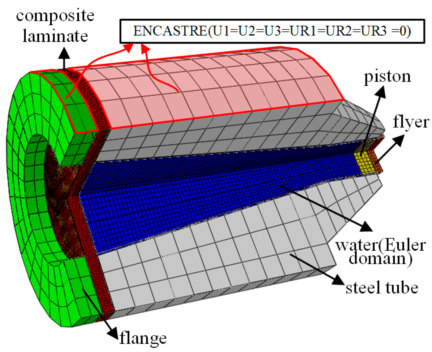
The details of the experimental setup are depicted in Figure 1. Taking the FSI effect into account, the experimental setup is capable of generating an exponentially decaying underwater shock wave, similar to that of an explosive blast. The loading system mainly consists of a flyer, piston, steel tube, target, and flange. The high-pressure gas generated by the light gas gun drives the flyer, which passes through the pipeline at high speed and then strikes the piston. The stress wave produced by the collision continuously transmits and reflects at the interface between the piston and water, forming an equivalent shock wave that decays exponentially within the water target chamber pipeline, ultimately acting on the target plate. In the experiment, the thickness of the flyer and the piston is 5 mm and 22 mm, respectively. The cavity inside the steel tube, filled with water to simulate the underwater environment, is divided into cylindrical and frustum sections with an inner diameter of 66 mm and 152.4 mm, featuring a 7-degree diffuser angle. The total length of the steel tube is 406 mm, with the cylindrical section being 76 mm long.
The velocity of the flyer plate is determined by timing its passage between two laser beams separated by a distance of 50 mm. This time interval is captured using the BC-202 dual-channel detonation velocity meter, which is manufactured by Kaifeng Precision Instrument Factory (Kaifeng, China) and offers microsecond-level precision in its measurements. The pressure measurement setup comprises piezoelectric pressure sensors, a charge amplifier, and an oscilloscope. The pressure sensors are the AE-YD-01-250MPa model, developed by Nanjing Aier Sensing Technology Co., Ltd. (Nanjing, China), and feature a response time of less than 1 μs. Through experimental observations, we have noted that sensors positioned close to the piston are susceptible to damage and experience substantial pressure fluctuations. To mitigate this issue, we opted to use a fixture without sensors to seal the water target chamber during the experiment. Consequently, pressure data were collected at only two locations, specifically points B and C as indicated in Figure 1a. The pressure sensors convert the shock wave pressure into electrical signals. These signals are then amplified by the charge amplifier, converted into digital form, and displayed and recorded on the Tektronix oscilloscope. With a sampling frequency set at 5 MHz, we ensure that no pressure information is lost during the measurement process. For displacement measurement, we employ a combination of two high-speed cameras and a 3D-DIC (Digital Image Correlation) system. The cameras capture images of the deformation process, while the 3D-DIC system calculates the displacement field both temporally and spatially. The cameras are positioned at an angle of approximately 20° to each other and are each about 2 m away from the target plate. During the experiment, the cameras operate at a frame rate of 50,000 frames per second. The captured images are subsequently processed using the VIC-3D digital image processing software, which is developed by CSI (Columbia, SC, USA).
According to Taylor’s classic analysis, the shock wave pressure of an underwater explosion can be expressed as
p ( t ) = p 0 e t / θ
where p 0 is the peak pressure and θ is the decay time. They are determined by the mass per unit area m ¯ f and the impact velocity v 0 of the flyer,
p 0 = ρ w c w v 0
θ = m ¯ f ρ w c w
I 0 = 2 0 t p ( t ) d t = 2 p 0 θ
To compare the response of various sandwich structures under different impulse loadings, the dimensionless impulse concept [3] is employed here,
I ^ = I 0 m ¯ σ y / ρ
where m ¯ is the mass per unit area, σ y is the yield stress, and ρ is the density of the target, respectively.

2.2. Specimen Details

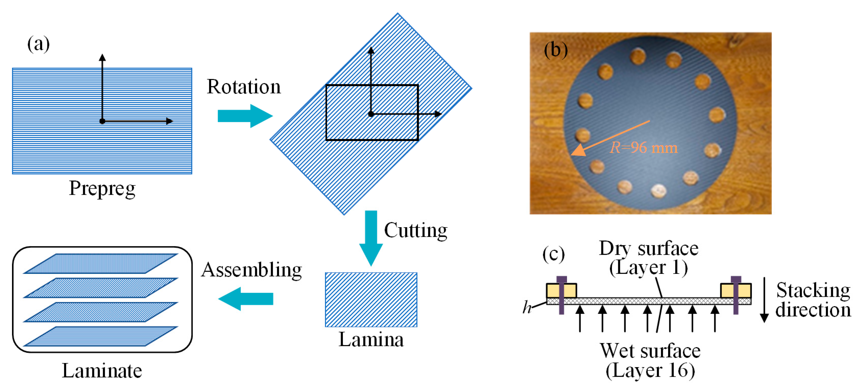
CFRP laminates of different thicknesses were fabricated using unidirectional carbon fiber/epoxy prepreg sheets through hot pressing technology. The prepreg sheets used were of the Toray T700SC type, with a fiber diameter of 7 μm and an epoxy resin system consisting of Araldite LY 5052/Aradur 5052 produced by Huntsman Advanced Materials (Basel, Switzerland). The specific prepreg material employed was Toray T700SC-12K-50 produced by Toray Industries, Inc. (Tokyo, Japan). The fabrication process involved hot pressing the stacked prepreg sheets at 180 °C and 1 MPa for 2 h, followed by post-curing at 120 °C for an additional 2 h to ensure complete polymerization and optimal mechanical properties. The material parameters of the unidirectional prepreg provided by the manufacturer are shown in Table 1. Unidirectional laminated boards are laid at specific angles along the direction of the core tape, with an average thickness of 0.25 mm per layer, as shown in Figure 2a. Then, use a water jet cutting machine to cut the laminate panel into a sample with a radius of 96 mm, as shown in Figure 2b. The thickness of the sample is h, and it is fixed between the flange and the tube chamber by bolt fastening, with one side subjected to underwater impact loading as shown in Figure 2c. Here, the first layer in contact with the air interface is defined as the dry surface, and the last layer in contact with the water interface is defined as the wet surface.

2.3. Material Properties

The constitutive models of different materials are as follows. The state equation of water is defined as
p = ρ w c w η ( 1 s 1 η ) 2 ( 1 Γ 0 η 2 ) + Γ 0 ρ w E m
where s 1 is the EOS coefficient, Γ 0 is the Grüneisen coefficient, E m is the specific energy, and η is the nominal volumetric compressive strain obtained by η = 1 ρ w / ρ [3]. c w and s 1 define linear impact velocity u s and particle velocity u p , with a linear Hugoniot relationship
u s = c w + s 1 u p
Table 2 lists the material properties of water [3].
The materials of the steel tube, flange, flyer, and piston are AISI 4340 steel. A plastic constitutive model with exponential hardening is adopted. The performance parameters [3] are listed in Table 3.
The laminates are manufactured using T700/BA9916 produced by Jiangsu Boshi Carbon Fiber Technology Co., Ltd. (Nanjing, China). The T700/BA9916 epoxy composite material exhibits both brittleness and anisotropy, necessitating a constitutive relationship that accounts for both the elastic phase and the damage phase. During the element damage analysis process, the damage criteria are used to identify the damage within elements. For areas where damage occurs, a reduced stiffness matrix is utilized for subsequent calculations. Based on the continuum damage mechanics, this paper employs the energy hypothesis proposed by Cordebois to construct the reduced stiffness matrix after damage. The three-dimensional constitutive equation for composite material damage using the Voigt notation can be defined as follows:
σ 1 d σ 2 d σ 3 d τ 23 d τ 13 d τ 12 d = Q d ε 1 ε 2 ε 3 γ 23 γ 13 γ 12 = Q 11 d Q 12 d Q 13 d 0 0 0 Q 21 d Q 22 d Q 23 d 0 0 0 Q 31 d Q 32 d Q 33 d 0 0 0 0 0 0 Q 44 d 0 0 0 0 0 0 Q 55 d 0 0 0 0 0 0 Q 66 d ε 1 ε 2 ε 3 γ 23 γ 13 γ 12
Among them, Q d represents the reduced stiffness matrix after damage, which is a symmetric second-order matrix; σ d is the effective stress vector; and ε is the strain vector. The definitions of the non-zero components in the reduced stiffness matrix are as follows:
Q 11 d = Q 11 1 d 1 Q 22 d = Q 22 1 d 2 Q 33 d = Q 33 1 d 3 Q i j d = Q i j 1 d i 1 d j Q 44 d = Q 44 1 d 1 1 d 2 Q 55 d = Q 55 1 d 1 1 d 3 Q 66 d = Q 66 1 d 2 1 d 3
where i , j = 1 , 2 , 3 and i j ; d1, d2, and d3 are Murakami damage variables, representing fiber breakage, matrix cracking, and delamination, respectively. Each damage variable di signifies the extent of damage in the i-th direction. Specifically, the first direction aligns with the fiber orientation, the second with the transverse direction within the ply plane, and the third with the thickness direction of the laminate. These damage variables range from 0 to 1, where 0 indicates an undamaged state and 1 signifies complete damage in the i-th direction.
The Hashin criteria are utilized in this paper to assess damage initiation in elements during dynamic processes. The damage initiation criterion employed is the three-dimensional Hashin criterion, formulated as quadratic strain, and it encompasses three principal damage modes: fiber tensile or compressive damage, matrix tensile or compressive damage, and delamination. These modes are defined by the following equations:
D 1 2 = ε 1 ε 1 f , t 2 + γ 12 ε 12 f 2 + γ 13 ε 13 f 2 1 ε 1 0 ε 1 ε 1 f , c 2 1 ε 1 < 0
D 2 2 = ε 2 + ε 3 2 ε 22 f , t ε 33 f , t ε 2 ε 3 ε 23 f 2 + γ 12 ε 12 f 2 + γ 13 ε 13 f 2 + γ 23 ε 23 f 2 1 ε 2 + ε 3 0 ε 2 + ε 3 2 ε 2 f , c ε 3 f , c + ε 2 + ε 3 ε 2 f , c ε 2 f , c 2 ε 12 f 1 ε 2 ε 3 ε 23 f 2 + γ 12 ε 12 f 2 + γ 13 ε 13 f 2 + γ 23 ε 23 f 2 1 ε 2 + ε 3 < 0
D 3 2 = ε 3 ε 3 f , t 2 + γ 13 ε 13 f 2 + γ 23 ε 23 f 2 1 ε 3 0 ε 3 ε 3 f , c 2 + γ 13 ε 13 f 2 + γ 23 ε 23 f 2 1 ε 3 < 0
ε i f , t = σ i f , t / Q i i ε i f , c = σ i f , c / Q i i ε 12 f = σ 12 f / Q 44 ε 13 f = σ 13 f / Q 55 ε 23 f = σ 23 f / Q 66
where σ i f , t and σ i f , c are the tensile and compressive strengths of the material in the three principal directions, respectively; σ 12 f , σ 13 f and σ 23 f represent the shear strengths.
The reduced stiffness matrix of the damaged material is controlled by the damage variables d1, d2, and d3. Typically, material degradation models can lead to mesh dependency, meaning that the computational results are not objective for refined mesh calculations. To alleviate the mesh dependency during the strain softening process, fracture energy and element characteristic length Lc are introduced into the damage evolution law to reduce mesh dependency. For the nonlinear degradation model selected in this study, the calculation of the damage variables is as follows:
d 1 = 1 1 D 1 e σ 1 f ε 1 f L c D 1 1 / G 1 f d 2 = 1 1 D 2 e σ 2 f ε 2 f L c D 2 1 / G 2 f d 3 = 1 1 D 3 e σ 3 f ε 3 f L c D 3 1 / G 3 f
where G 1 f , G 2 f , G 3 f represent the fracture toughness of the material in three directions, respectively. For the damage stage, the model employs the three-dimensional Hashin failure criterion introduced in the previous section to describe the initiation and evolution of damage in this material. Table 4 provides the strength parameters and the fracture energy at failure for the T700/BA9916 epoxy composite material, which are provided by the manufacturer.

2.4. Simulation Model

Numerical simulations are conducted using ABAQUS’s explicit algorithm, with model dimensions matching the experimental setup. The boundary conditions are equivalent to the actual scenario, applying fixed constraints to the outer surfaces of the flange and the tube. The general contact is adopted in the numerical model. As shown in Figure 3, the entire model, excluding the water, is constructed using the Lagrangian formulation and meshed with C3D8R elements. To simplify the analysis, the model excludes bolt holes in the flange and the tube, applying fixed constraints in corresponding places. An Euler domain is set up and populated with water to reflect the actual proportions. This domain necessitates a fine mesh to accurately capture the incident wave’s shock, which is crucial for the analysis of fluid–structure interactions.
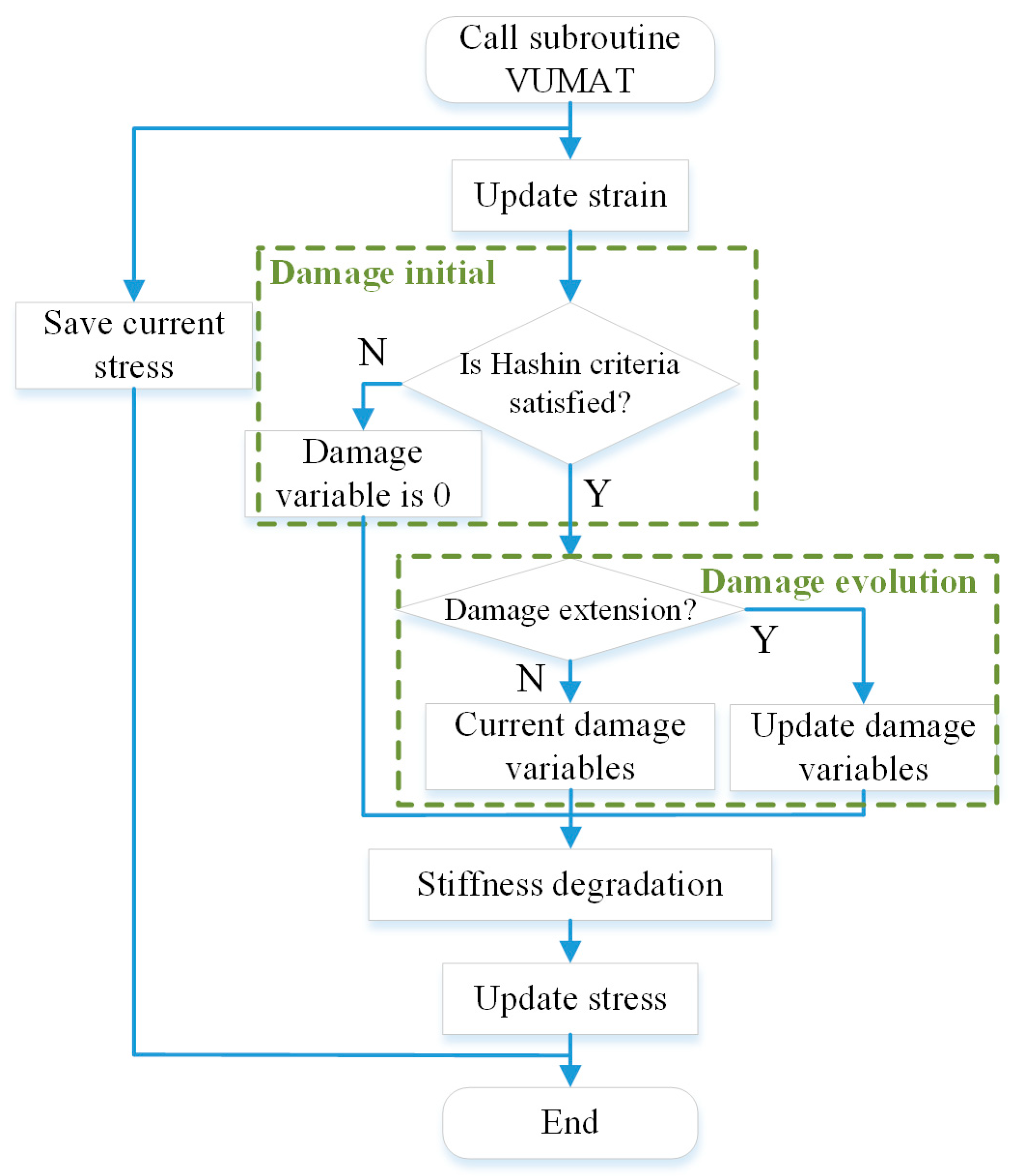
The material subroutine VUMAT within ABAQUS 6.20 software is utilized to simulate the initiation and evolution of damage in composite laminates, as shown in Figure 4. The process begins with extracting state variables from the ABAQUS solver at each integration point, including stress, strain, and damage variables. It then evaluates the potential for damage initiation at each material point using the Hashin failure criteria. Upon detecting material failure, the subroutine assesses the damage extent and recalculates the stress based on the constitutive relationship and damage variables. If the principal strain at any material point reaches a critical threshold, the affected element is removed from the model. Ultimately, the updated state variables are fed back into the ABAQUS solver for further computations.

3. Experimental and Simulation Results

3.1. Shock Wave Propagation

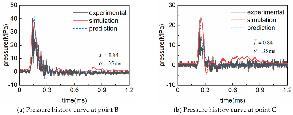
The experimental and simulation results of the composite laminate with a ply orientation of [0/90/±45]2s subjected to a dimensionless impulse of 0.84 are mainly analyzed here. In the experiment, the speed of the flyer is 97.78 m/s. The pressure history measured by pressure sensors, calculated by the numerical simulation, and predicted by Equations (1)–(3) are shown in Figure 5. The curve obtained from the experiment oscillates more severely. In contrast, the simulated curve is smoother, due to the viscosity coefficient introduced in the simulation that flattens the curve to a certain extent. The viscosity coefficient was introduced to account for the damping effects that are inherent in real-world water materials. These damping effects can arise from various sources, including interfacial friction and other dissipative mechanisms. Through iterative testing and comparison with experimental data, we determined an optimal value for the viscosity coefficient that provides a good balance between smoothing the curve and preserving the essential features of the water’s response. This optimal value was chosen based on the best fit to experimental data, ensuring that the simulation accurately reflects the real-world behavior of the water. The comparison of peak pressure is summarized in Table 5, where p B and p C represent the peak pressure at points B and C in Figure 1, respectively. The errors between simulated and experimental values are 4.2% and 5.8%, respectively, which indicates that the simulation models are valid in this paper.
Figure 6 shows the flow field pressure obtained from numerical simulation. From 0 to 0.3 ms, shock waves generated by the impact propagate in the form of plane waves, and the peak pressure gradually decreases with increasing distance.

3.2. Deformation History

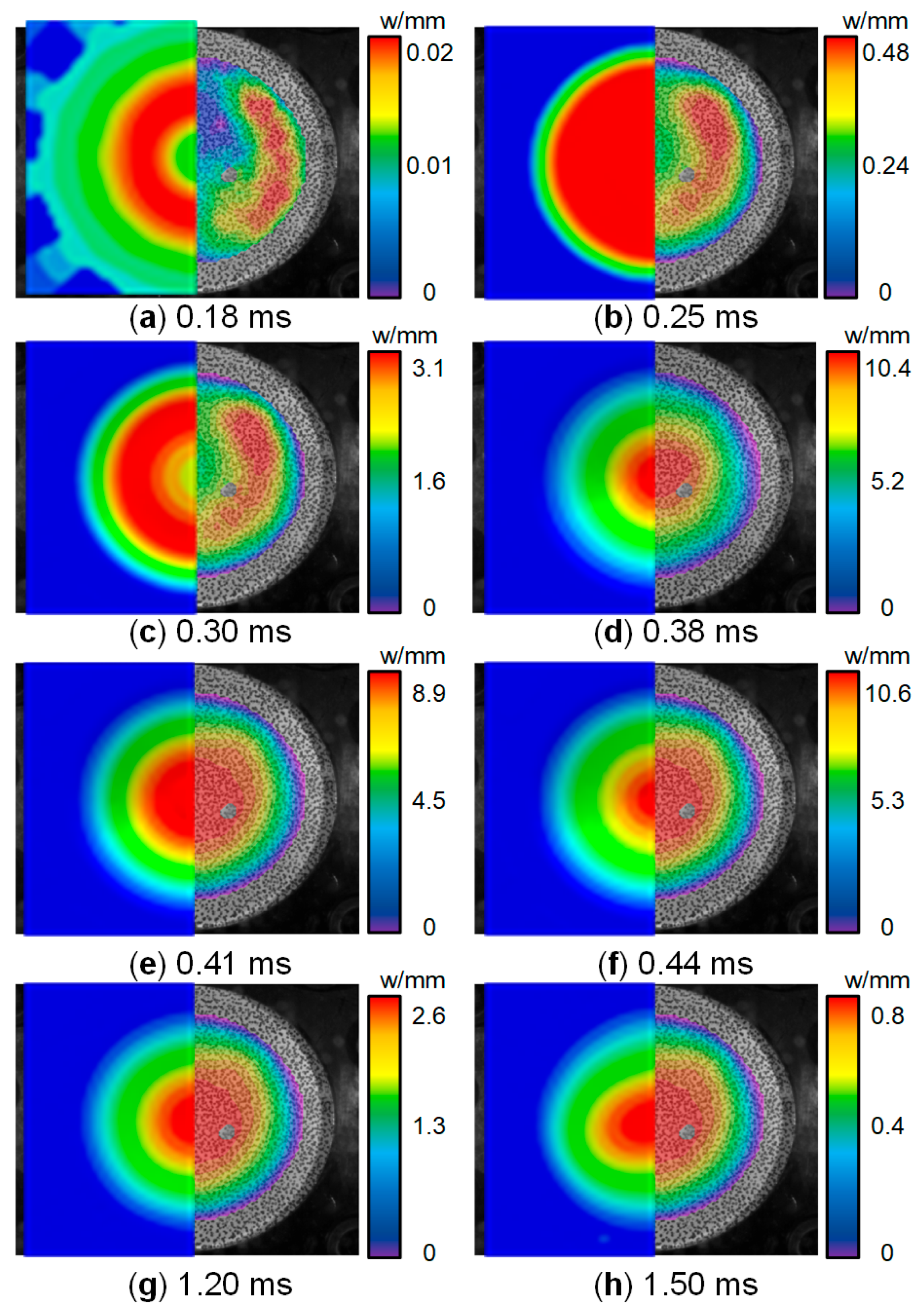
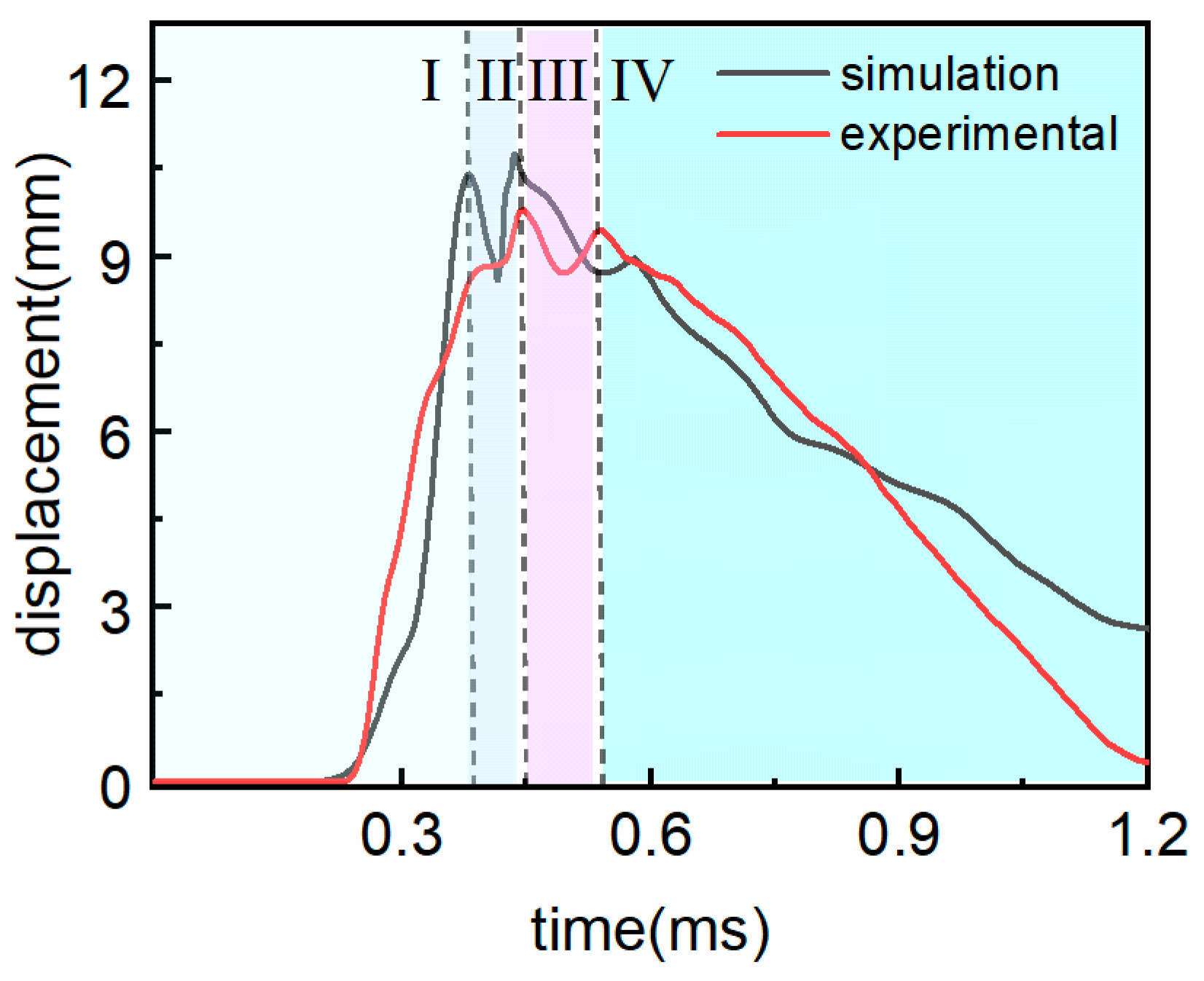
Figure 7 shows the deformation field history of the laminate subjected to a dimensionless impulse of 0.84. These images reveal the fluctuation characteristics of impact loads and the deformation of structures as they interact with the fluid. The laminate with [0/90/±45]2s ply exhibits in-plane properties that are close to those of an isotropic material. Therefore, after being subjected to underwater impact loading, the deformation field is almost circular. The deflection–time curve of the laminate’s central point is shown in Figure 8. The dynamic deformation response process of the laminate can be divided into four stages:
Stage I is the initial loading stage. From 0.25 ms to 0.34 ms, as shown in Figure 7c, the deformation at the periphery of the laminate is greater than that at the center, causing the laminate to take on a “w” shape. Subsequently, as the pressure at the center of the laminate increases, the deformation at the center becomes greater than that at the periphery, causing the laminate to take on a “v” shape. The deformation value reaches its first peak of 10.4 mm at 0.38 ms.
Stage II is the first elastic recovery stage. The fixing effect of the flange causes the laminate to recover its elastic deformation for the first time, as shown in Figure 7e, reaching a minimum value of 8.9 mm at 0.41 ms, which recovered 14.4% compared to the first peak value.
Stage III is the secondary loading stage. During the recovery of elastic deformation, the shock wave generated by cavitation loads the laminate a second time, causing the deformation of the laminate to increase again, as shown in Figure 7f. The deformation of the laminate reaches its second peak value of 10.7 mm at 0.44 ms.
Stage IV is the secondary elastic recovery to the stability stage. The shock wave pressure is too low to resist the elastic recovery of the laminate, and the deformation of the laminate continues to decrease, reducing to 2.6 mm at 1.2 ms, 0.9 mm at 1.5 ms, and eventually approaching zero.

3.3. Damage Mechanisms

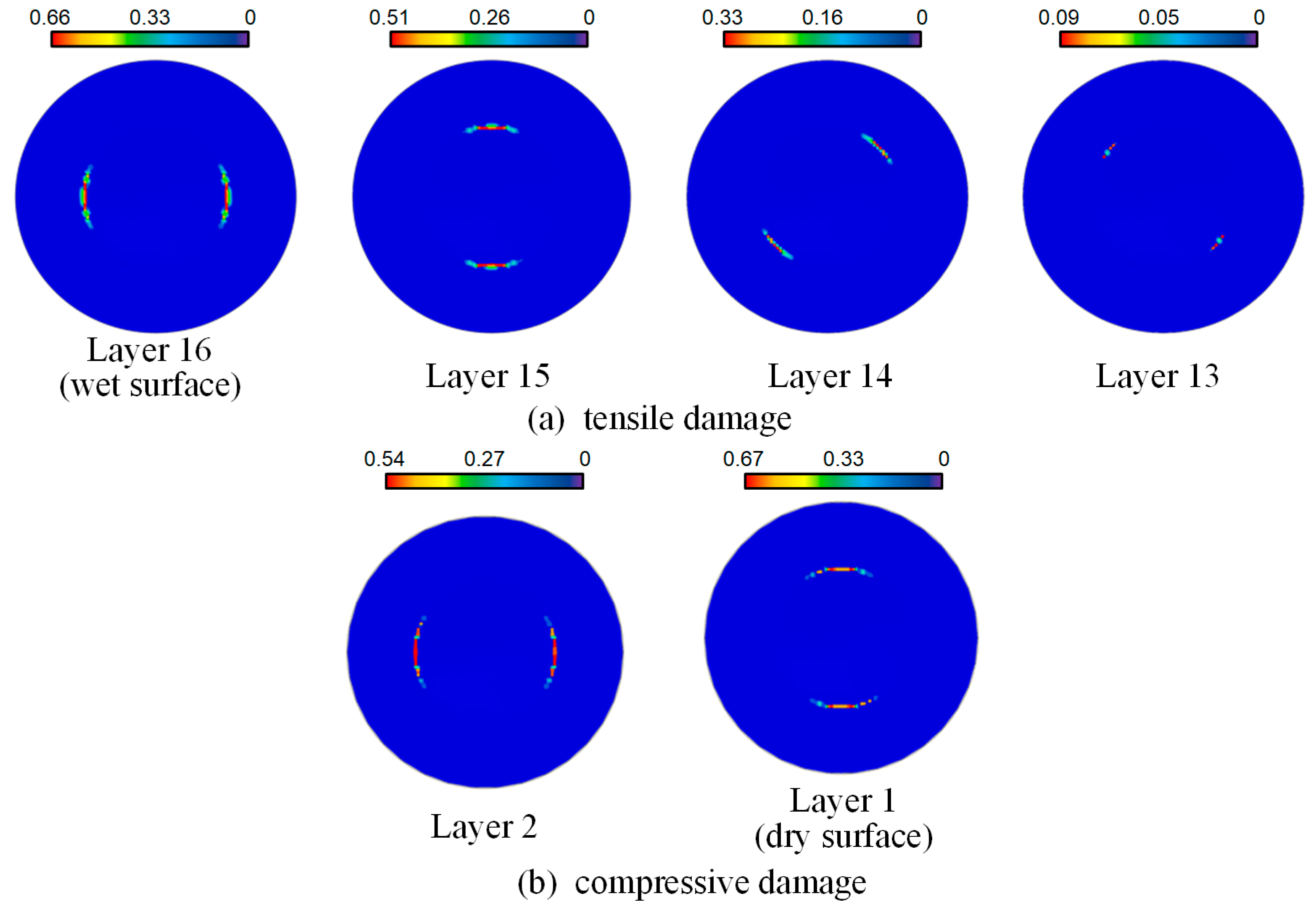
When laminates are subjected to high-speed impact, damage to the matrix or fibers may occur. Analysis of the compressive and tensile damage to fibers and the compressive and tensile damage to the matrix in each layer of the laminate reveals the following: The primary damage mode of the laminate is tensile damage to the matrix, which occurs throughout the entire laminate; tensile damage to fibers occurs in the several layers of the laminate near the dry surface; compressive damage to fibers occurs in the several layers of the laminate near the wet surface; there is no compressive damage to the matrix.
The tensile damage condition of the matrix in each layer after the laminate is impacted is shown in Figure 9. Due to the strong anisotropy of the individual plies, the modulus and strength perpendicular to the fiber direction are much lower than those along the fiber direction. Consequently, damage perpendicular to the fiber direction is more significant, resulting in an elliptical shape for the tensile damage to the matrix within the ply, with the axis of symmetry of the damaged area perpendicular to the fiber direction, as shown in Figure 9. The area of the damaged area accounts for approximately 35% of the area affected by the impact. The matrix damage gradually transitions from the edges towards the center, with the degree of damage decreasing from 0.22 to 0.20 and then increasing back to 0.22, which is essentially symmetrical and consistent with the symmetrical layup of the laminate. The elliptical damage pattern observed in the composite material can be attributed to the anisotropic nature of the material’s stiffness and strength properties. The major and minor axes of the ellipse correspond to the principal directions of the material’s stiffness. The elliptical pattern indicates that the material is stiffer in the fiber direction compared to the transverse direction. The transverse direction (minor axis) is relatively weaker, leading to more pronounced damage in this direction.
The fiber damage conditions of the laminate are shown in Figure 10. The wet surface of the laminate is directly subjected to the impact of the shock wave. Near the boundary region of the wet surface plies, fiber tensile damage occurs, with the axis of symmetry of the damage area parallel to the fiber direction. The fiber tensile damage on the wet surface is the most severe, with a damage variable of 0.66, and the maximum damage variable of the 13th layer is 0.09. The layer near the center has almost no fiber tensile damage. Near the center of the dry surface plies, fiber compressive damage occurs with the axis of symmetry parallel to the fiber direction, at the boundary region. The fiber compression damage on the dry surface is the most severe, with a damage variable of 0.67, and the maximum damage variable on the second layer is 0.54. The layer near the center has almost no fiber compression damage. The parallel pattern indicates that damage propagates along the fiber directions. The strength parameters (tensile strength in the fiber and transverse directions) dictate the path and extent of damage. The high strength in the fiber direction (0°) and the relatively lower strength in the transverse direction (90°) contribute to the observed damage patterns.
Comparing fiber damage with matrix damage reveals that the matrix damage covers a larger area but is less severe, whereas fiber damage covers a smaller area but is more severe. The matrix material plays a crucial role in transferring loads between fibers and maintaining the structural rigidity of the composite. Microcracks and debonding within the matrix can disrupt this load transfer mechanism, resulting in a noticeable decrease in stiffness. Extensive matrix damage can also lead to delamination, which is the separation of layers within the composite. Delamination significantly reduces the load-bearing capacity of the composite and can propagate under continued loading, leading to catastrophic failure. The presence of microcracks can act as initiation points for delamination, making the composite more susceptible to this type of failure. Fibers are the primary load-bearing components of the composite. The presence of fiber damage can significantly reduce the ultimate strength of the composite. Since fibers are responsible for providing the primary strength to the composite, their failure directly impacts the material’s ability to withstand maximum loads. Localized fiber breakage can quickly propagate, leading to a rapid reduction in the composite’s ability to withstand applied loads. When fibers fail, the load is redistributed to the surrounding fibers and matrix material. This can lead to increased stress concentrations in adjacent regions, potentially causing further damage and failure.
In summary, the primary damage mode of the laminate is tensile damage to the matrix, and the failure mode of the laminate may be tensile or compressive failure of fibers in the boundary or central region of the laminate.

3.4. Energy Response

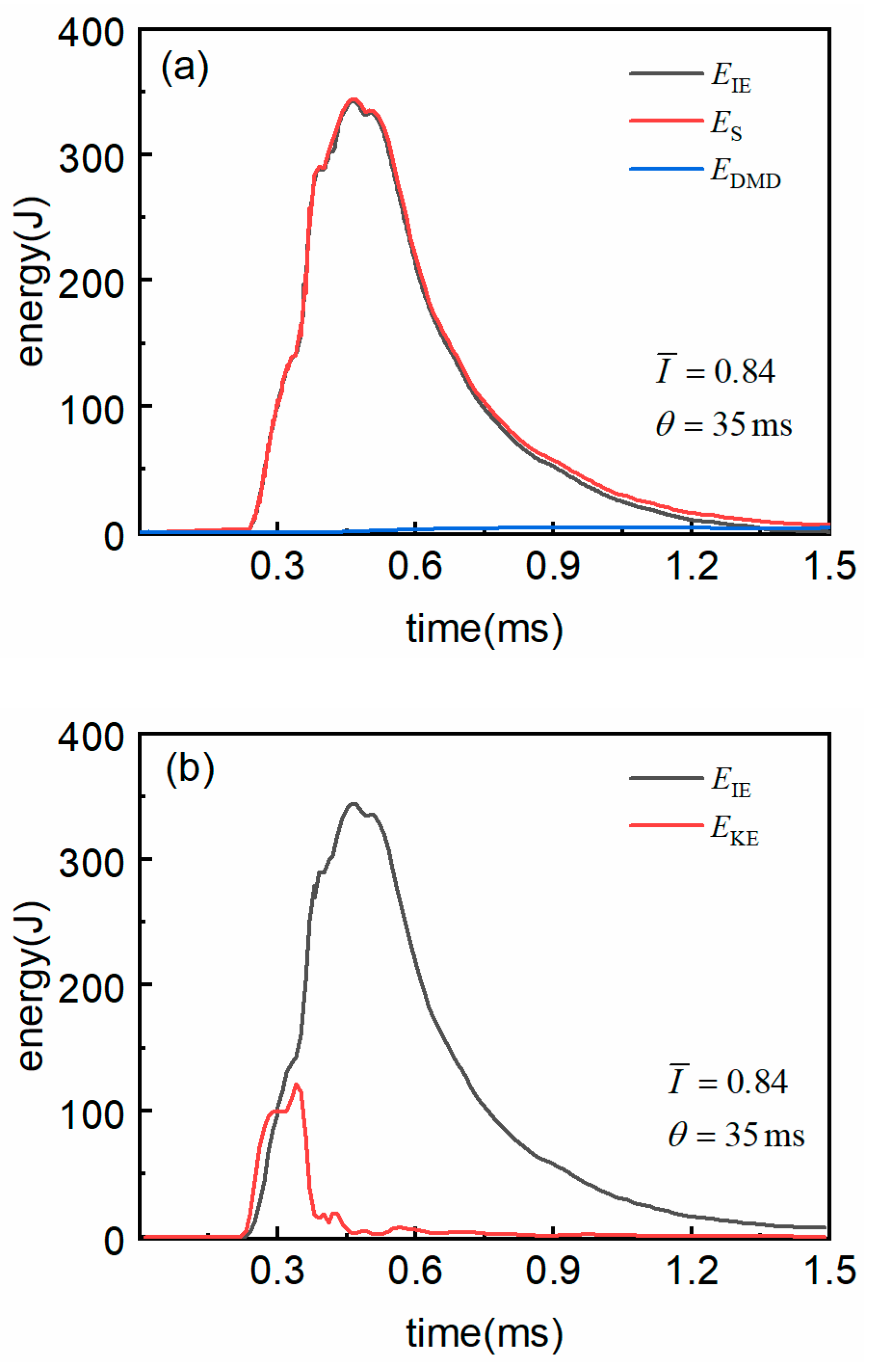
Kinetic energy EKE is generated in the laminate after it is subjected to an underwater shock wave. The deformed area resulting from the loading will have a certain velocity, and the kinetic energy of the laminate mainly comes from a portion of the kinetic energy of the shock wave. Internal energy EIE is the strain energy ES produced after the laminate deforms and the dissipated energy EDMD by the matrix and fibers due to crack absorption during impact. The dynamic response processes of the laminate’s internal energy, strain energy, and damage dissipation energy are shown in Figure 11a. It is observed that the variation curve of internal energy almost completely coincides with that of strain energy. This is because the strain energy generated by the deformation of the laminate under impact greatly exceeds the energy absorbed by the matrix and fiber fractures in the laminate; hence, strain energy is the primary factor causing changes in internal energy.
The dominance of strain energy over internal energy suggests that the laminate has a significant capacity to store and release energy elastically. This is indicative of the material’s ability to undergo deformation and then return to its original state with minimal residual deformation. The [0/90/±45]2s quasi-isotropic layup, in particular, provides a balanced distribution of stiffness and strength in multiple directions, which enhances the material’s ability to recover from deformation. The dominance of strain energy also suggests that the laminate can absorb and dissipate energy effectively, which is beneficial for impact-resistant applications. This characteristic is crucial for applications requiring repeated loading and unloading cycles and contributes to the overall durability and performance of the composite.
The dynamic energy response process of the laminate under impact is shown in Figure 11b. It is found that the variation trends of the laminate’s kinetic energy and internal energy are related to the deformation trend of the laminate: around 0.25 ms when the laminate is subjected to the shock wave, the laminate deforms and gains velocity, causing the kinetic energy of the laminate to gradually increase; due to the fixing effect of the flange, the velocity of the laminate drops rapidly around 0.45 ms, and the kinetic energy also decreases rapidly; before the kinetic energy drops to zero, the deformation of the laminate continues to increase, reaching its maximum value at 0.45 ms when the velocity is zero, and the internal energy also reaches its maximum value; thereafter, as the elastic deformation recovers, the velocity of the laminate slightly increases, the kinetic energy slightly increases and then gradually decreases to zero, and the internal energy of the laminate also gradually decreases as the strain energy is released.

4. Parameter Analysis

The method of numerical simulation was utilized to explore the impact of varying parameters on the dynamic response of composite laminates, with a particular focus on the impact intensity, the ply orientation of the laminate, and the thickness of the laminate. This research provides a theoretical foundation for the optimized design of composite laminate structures.

4.1. Influence of Impact Intensity

The dynamic response of the laminate with a thickness of 4 mm and a [0/90/±45]2s ply sequence under different dimensionless impact intensity was investigated without causing damage to the laminate. The damage dissipation energy of the laminate can directly reflect the degree of damage to the laminate. Figure 12 shows the damage dissipation energy of the laminate at different impact velocities. It is observed that as the fragment velocity increases, the impact intensity on the laminate increases, resulting in a greater slope of the damage dissipation energy and a higher peak value. This indicates that the greater the impact intensity, the faster the response of the laminate to damage, and the more severe the damage.
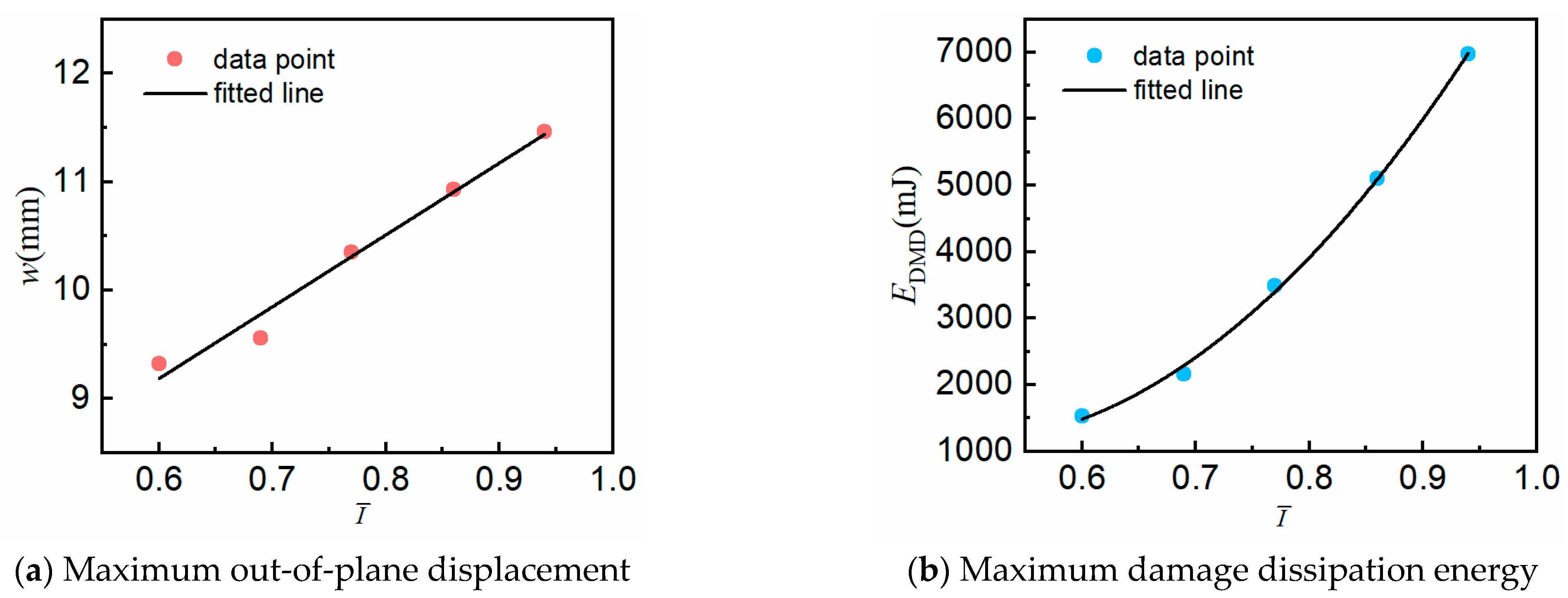
The maximum out-of-plane displacement and maximum damage dissipation energy of the laminate under different impact intensities are shown in Table 6. Figure 13 shows the fitted plots of these two parameters varying with impact intensity. Both have R-squared values exceeding 0.98, indicating a very good fit. It was found that under the condition where the laminate does not fail, the maximum out-of-plane displacement of the laminate is approximately linearly related to the impact intensity, and the maximum damage dissipation energy is approximately quadratically related to the impact intensity. It can be reasonably inferred that the deformation of the laminate is linearly related to the impact intensity, while the damage of the laminate is quadratically related to the impact intensity.

4.2. Influence of Ply Orientation

To conduct an in-depth study on the stiffness matrix of composite laminates with the same thickness but different ply orientations, laminates with a thickness of 4 mm and different ply orientations were investigated. The [0]8s configuration represents a unidirectional layup, which provides high stiffness and strength in the fiber direction. This type of layup is often used when the primary loading is expected to be along the fiber direction, and it is useful for understanding the maximum performance that can be achieved in a specific direction. The [0/90]4s configuration is a cross-ply layup. This layup provides a balance of stiffness and strength in both the longitudinal and transverse directions. Cross-ply laminates are commonly used in applications where loading is multidirectional. The [0/90/±45]2s configuration represents a quasi-isotropic layup. The inclusion of the ±45° layers helps to provide isotropic-like behavior, meaning that the laminate has similar mechanical properties in all directions. Quasi-isotropic laminates are particularly useful for applications where the loading is multidirectional and complex, as they provide a more uniform response to different loading conditions. A continuous shell element was used to model these laminates. Under the same dimensionless impact intensity of 0.84, numerical simulations were performed to analyze the dynamic response of these laminates under equivalent underwater shock loading. The deformation response curves at the center point of the three laminates, as obtained from the simulations, are shown in Figure 14.
The findings from the simulation are as follows: The [0]8s laminate exhibited the fastest response, minimal deformation, reached its peak value earliest, and also recovered at the fastest rate. The [0/90]4s laminate had the slowest response, maximum deformation, reached its deformation peak latest, and failed to stabilize during the recovery phase. The [0/90/±45]2s laminate and the [0]8s laminate had very close maximum deformation values, but the [0/90/±45]2s laminate recovered faster during the elastic recovery stage than the [0]8s laminate. This is related to the lower damage in the [0/90/±45]2s laminate. In summary, the deformation response curves of the laminates indicate that by designing the ply orientation of the laminate, the anisotropy of the laminate can be improved, which in turn enhances the deformation response of the laminate under impact.
Comparing the maximum out-of-plane displacement values of the [0]8s and [0/90]4s layups, it is found that the addition of [0/90/±45]2s plies reduces the maximum out-of-plane displacement of the laminate by 0.55 mm compared to the unidirectional layup, which is a 2.2% decrease. Within the [0/90]4s layup, the addition of [0/90/±45]2s plies further reduces the maximum out-of-plane displacement of the [0/90/±45]2s laminate by 0.155 mm compared to the orthogonal [0/90]4s layup, a 1.4% decrease. By comparing the maximum out-of-plane displacements, it is once again confirmed that the ply design of the laminate can improve the deformation response of the laminate after impact.
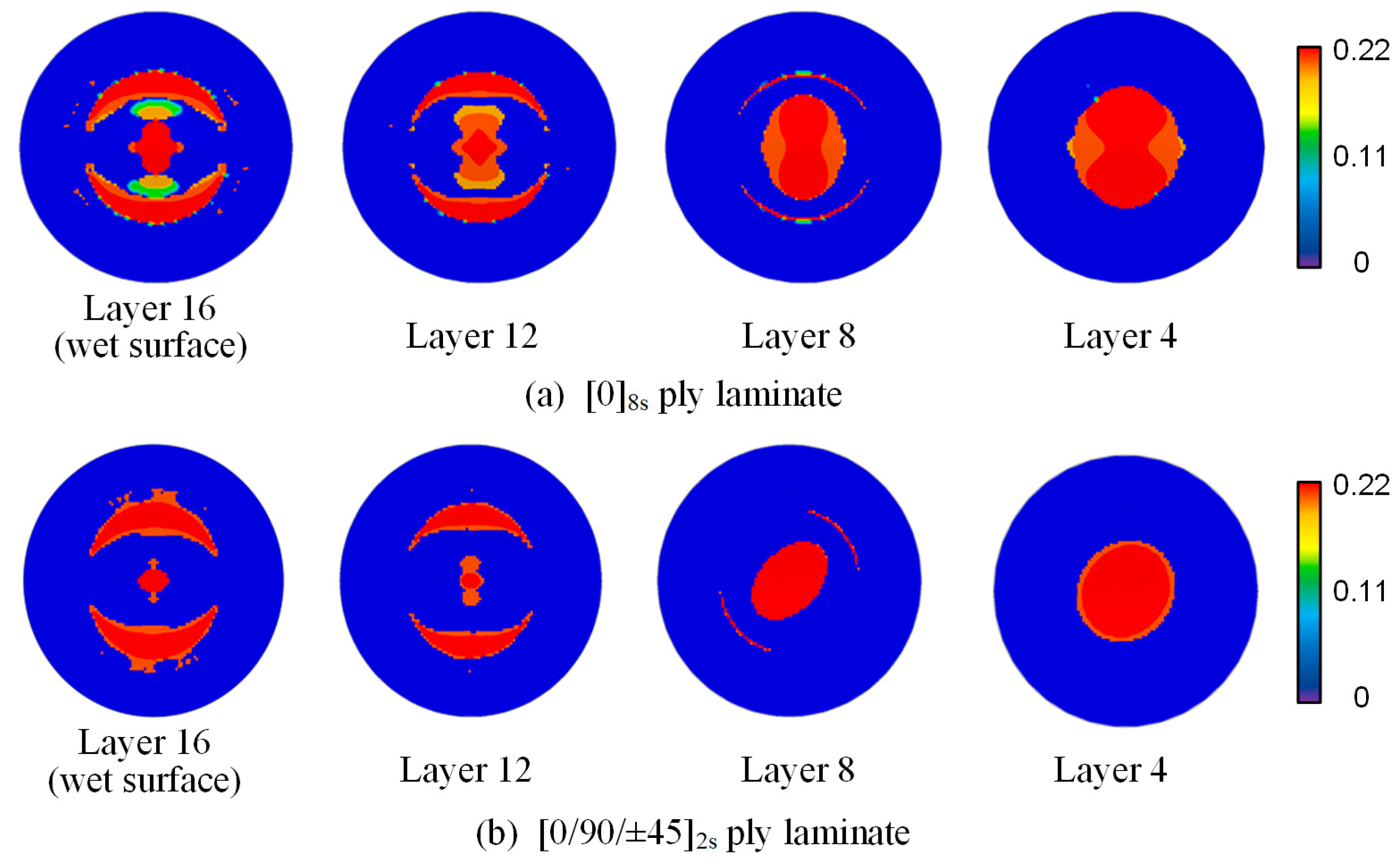
Matrix tensile damage is the primary mode of damage for laminates; hence, a focused comparison was made between the matrix tensile damage cloud maps of each layer for the [0]8s and [0/90/±45]2s ply laminates after impact, as shown in Figure 15.
In Figure 15, it can be observed that the damage areas in the [0]8s laminate are consistently distributed along the 2-axis and are elliptical in shape. This is due to the fact that the fiber direction in the [0]8s laminate is always aligned with the 1-axis, and the strength perpendicular to the fiber direction is much lower than that along the fiber direction. Consequently, the matrix is more susceptible to tensile damage perpendicular to the fiber direction upon impact. In contrast, the damage areas in the [0/90/±45]2s laminate are distributed differently because the fiber direction in this laminate is oriented at 45 degrees to the axes. As a result, damage is more likely to occur in sections that are perpendicular to the fiber direction. Upon comparing the degree and area of damage in each layer of the two types of laminates, it is found that both the degree and area of damage in the [0]8s laminate are less than those in the [0/90/±45]2s laminate. This indicates that by altering the ply orientation of the laminate, the anisotropy of the laminate can be improved, which in turn enhances the damage response of the laminate after impact.

4.3. Influence of Laminate Thickness

This section investigates the effect of thickness variation on the dynamic response of composite laminates by altering the thickness of individual plies, while keeping the impact intensity and ply orientation constant. Figure 16 shows the deformation response curves of laminates with different thicknesses under the same underwater shock load, with a dimensionless impact intensity 0.84 and a ply angle of [0/90/±45]2s. The comparison reveals that as the thickness of the laminate increases, the time it takes for the laminate to reach its maximum deformation decreases, and the maximum out-of-plane displacement of the laminate becomes smaller. However, the maximum out-of-plane displacement does not decrease linearly; instead, the reduction in displacement diminishes progressively with increasing thickness.
Table 7 presents the maximum out-of-plane displacement values and the reductions in these displacements for composite laminates of varying thicknesses. It is observed that when the thickness of the laminate is relatively small, increasing the thickness significantly reduces the maximum out-of-plane displacement. However, once the thickness reaches a certain value, further increases in thickness result in a gradually diminishing reduction in maximum out-of-plane displacement. As the thickness increases, the reduction in maximum out-of-plane displacement under impact decreases. Specifically, beyond 6 mm, the reduction in maximum out-of-plane displacement is less than 10% per additional millimeter of thickness. This implies that beyond a certain thickness, continuing to increase the thickness will add to the cost without significantly enhancing the laminate’s deformation resistance under impact.

4.4. Discussion

This section provides a detailed discussion of the results obtained in this study and compares them with findings from previous studies. A comparative table is included to highlight the advantages, disadvantages, risks, and limitations of our results, as shown in Table 8.
Our study demonstrates that CFRP laminates exhibit high impact resistance under underwater shock loading, with significant elastic deformation and high recoverability. The use of quasi-isotropic layup [0/90/±45]2s reduces anisotropy and mitigates damage, providing better resistance to multidirectional loads. Our results provide clear guidelines for optimizing laminate thickness, with diminishing returns observed beyond 6 mm thickness.
Our study is limited to specific laminate configurations and materials. Further validation is needed for other materials and configurations. The findings are specific to the tested CFRP laminates and may not be directly applicable to other composite materials or structural forms. Additional experiments and simulations are required to validate the results for other materials and configurations, ensuring broader applicability.

5. Conclusions

Despite extensive research on composite laminates under air conditions, the complex fluid–structure interaction (FSI) effects encountered in underwater environments remain less explored. To address this gap, we employed a combination of experimental and numerical methods. The experimental setup included an underwater impact load simulator capable of generating planar shock pulses similar to those produced by underwater explosions. High-speed imaging at 50,000 frames per second and piezoelectric sensors were used to capture the deformation and pressure data. Numerical simulations using ABAQUS Explicit were conducted to validate the experimental results and provide a detailed analysis of the dynamic response and damage mechanisms. Four conclusions obtained from this experimental research are listed as follows.
(1) The established computational model effectively simulates the experimental loading process. Composite laminates primarily undergo elastic deformation, which is almost entirely recoverable. During deformation, damage to the fibers and matrix occurs, with the primary damage mode being tensile damage to the matrix.
(2) As the impact intensity increases, the maximum out-of-plane displacement of the laminate is approximately directly proportional to the impact intensity, and the maximum damage dissipation energy is approximately quadratically related to the impact intensity.
(3) The quasi-isotropic layup [0/90/±45]2s exhibits a more uniform distribution of flexural stiffness. This uniformity in stiffness distribution contributes to the reduced anisotropy and improved damage resistance observed in the quasi-isotropic layup.
(4) When the impact intensity and ply orientation are constant, increasing the laminate thickness from 3 mm to 8 mm reduces the maximum out-of-plane displacement by 32%, with diminishing returns observed beyond 6 mm thickness.
This study contributes to the development of advanced optimization algorithms to design composite laminates with tailored properties for specific applications, considering both mechanical and environmental factors. It also helps to conduct comprehensive cost–benefit analyses to determine the most cost-effective laminate configurations for different applications, balancing performance and economic considerations.

Author Contributions

Methodology, Z.W.; Software, Z.W.; Formal analysis, Z.W.; Investigation, Z.W.; Resources, J.R.; Data curation, Z.W.; Writing—original draft, Z.W.; Writing—review & editing, J.R.; Supervision, J.R.; Funding acquisition, J.R. All authors have read and agreed to the published version of the manuscript.

Funding

This research was funded by National Natural Science Foundation of China, (Grant No. 11972091).

Data Availability Statement

The data presented in this study are available on request from the corresponding author.

Acknowledgments

The authors would like to acknowledge the National Natural Science Foundation of China (Grant No. 11972091) for providing funding for conducting experiments.

Conflicts of Interest

The authors declare that they have no known competing financial interests or personal relationships that could have appeared to have influenced the work reported in this paper.

References

  1. Tran, P.; Wu, C.; Saleh, M.; Bortolan Neto, L.; Nguyen-Xuan, H.; Ferreira, A.J.M. Composite Structures Subjected to Underwater Explosive Loadings: A Comprehensive Review. Compos. Struct. 2021, 263, 113684. [Google Scholar] [CrossRef]
  2. Wanchoo, P.; Matos, H.; Rousseau, C.-E.; Shukla, A. Investigations on Air and Underwater Blast Mitigation in Polymeric Composite Structures—A Review. Compos. Struct. 2021, 263, 113530. [Google Scholar] [CrossRef]
  3. Espinosa, H.D.; Lee, S.; Moldovan, N. A Novel Fluid Structure Interaction Experiment to Investigate Deformation of Structural Elements Subjected to Impulsive Loading. Exp. Mech. 2006, 46, 805–824. [Google Scholar] [CrossRef]
  4. Liang, Y.; Spuskanyuk, A.V.; Flores, S.E.; Hayhurst, D.R.; Hutchinson, J.W.; McMeeking, R.M.; Evans, A.G. The Response of Metallic Sandwich Panels to Water Blast. J. Appl. Mech. 2007, 74, 81–99. [Google Scholar] [CrossRef]
  5. Mori, L.F.; Queheillalt, D.T.; Wadley, H.N.G.; Espinosa, H.D. Deformation and Failure Modes of I-Core Sandwich Structures Subjected to Underwater Impulsive Loads. Exp. Mech. 2009, 49, 257–275. [Google Scholar] [CrossRef]
  6. McShane, G.J.; Deshpande, V.S.; Fleck, N.A. Underwater Blast Response of Free-Standing Sandwich Plates with Metallic Lattice Cores. Int. J. Impact Eng. 2010, 37, 1138–1149. [Google Scholar] [CrossRef]
  7. Avachat, S.; Zhou, M. Response of Submerged Metallic Sandwich Structures to Underwater Impulsive Loads. J. Mech. Mater. Struct. 2015, 10, 17–41. [Google Scholar] [CrossRef]
  8. Avachat, S.; Zhou, M. High-Speed Digital Imaging and Computational Modeling of Dynamic Failure in Composite Structures Subjected to Underwater Impulsive Loads. Int. J. Impact Eng. 2015, 77, 147–165. [Google Scholar] [CrossRef]
  9. Avachat, S.; Zhou, M. Compressive Response of Sandwich Plates to Water-Based Impulsive Loading. Int. J. Impact Eng. 2016, 93, 196–210. [Google Scholar] [CrossRef]
  10. Avachat, S.; Zhou, M. High-Speed Digital Imaging and Computational Modeling of Hybrid Metal-Composite Plates Subjected to Water-Based Impulsive Loading. Exp. Mech. 2016, 56, 545–567. [Google Scholar] [CrossRef]
  11. Avachat, S.; Zhou, M. Novel Experimental and 3D Multiphysics Computational Framework for Analyzing Deformation and Failure of Composite Laminates Subjected to Water Blasts. Int. J. Impact Eng. 2017, 106, 223–237. [Google Scholar] [CrossRef]
  12. Huang, W.; Jia, B.; Zhang, W.; Huang, X.; Li, D.; Ren, P. Dynamic Failure of Clamped Metallic Circular Plates Subjected to Underwater Impulsive Loads. Int. J. Impact Eng. 2016, 94, 96–108. [Google Scholar] [CrossRef]
  13. Huang, W.; Zhang, W.; Li, D.; Ye, N.; Xie, W.; Ren, P. Dynamic Failure of Honeycomb-Core Sandwich Structures Subjected to Underwater Impulsive Loads. Eur. J. Mech.—A/Solids 2016, 60, 39–51. [Google Scholar] [CrossRef]
  14. Huang, W.; Zhang, W.; Huang, X.; Jiang, X.; Li, Y.; Zhang, L. Dynamic Response of Aluminum Corrugated Sandwich Subjected to Underwater Impulsive Loading: Experiment and Numerical Modeling. Int. J. Impact Eng. 2017, 109, 78–91. [Google Scholar] [CrossRef]
  15. Huang, W.; Zhang, W.; Ren, P.; Guo, Z.T.; Ye, N.; Li, D.C.; Gao, Y.B. An Experimental Investigation of Water-Filled Tank Subjected to Horizontal High Speed Impact. Exp. Mech. 2015, 55, 1123–1138. [Google Scholar] [CrossRef]
  16. Huang, W.; Zhang, W.; Chen, T.; Jiang, X.; Liu, J. Dynamic Response of Circular Composite Laminates Subjected to Underwater Impulsive Loading. Compos. Part A Appl. Sci. Manuf. 2018, 109, 63–74. [Google Scholar] [CrossRef]
  17. Xiang, D.-L.; Rong, J.-L.; He, X. Experimental Investigation of Dynamic Response and Deformation of Aluminium Honeycomb Sandwich Panels Subjected to Underwater Impulsive Loads. Shock Vib. 2015, 2015, 650167. [Google Scholar] [CrossRef]
  18. He, X.; Rong, J.L.; Xiang, D.L.; Wei, H.Y.; Hu, C.H.; Wang, X. The Influence of Flyer Momentum on an Aluminium Plate’s Response to Underwater Shock Loading. J. Mech. 2019, 35, 267–278. [Google Scholar] [CrossRef]
  19. LeBlanc, J.; Shukla, A. Dynamic Response and Damage Evolution in Composite Materials Subjected to Underwater Explosive Loading: An Experimental and Computational Study. Compos. Struct. 2010, 92, 2421–2430. [Google Scholar] [CrossRef]
  20. LeBlanc, J.; Shukla, A. Dynamic Response of Curved Composite Panels to Underwater Explosive Loading: Experimental and Computational Comparisons. Compos. Struct. 2011, 93, 3072–3081. [Google Scholar] [CrossRef]
  21. LeBlanc, J.; Shukla, A. Underwater Explosion Response of Curved Composite Plates. Compos. Struct. 2015, 134, 716–725. [Google Scholar] [CrossRef]
  22. Schiffer, A.; Tagarielli, V.L. The Response of Circular Composite Plates to Underwater Blast: Experiments and Modelling. J. Fluids Struct. 2015, 52, 130–144. [Google Scholar] [CrossRef]
  23. Latourte, F.; Grégoire, D.; Zenkert, D.; Wei, X.; Espinosa, H.D. Failure Mechanisms in Composite Panels Subjected to Underwater Impulsive Loads. J. Mech. Phys. Solids 2011, 59, 1623–1646. [Google Scholar] [CrossRef]
  24. Avachat, S.; Zhou, M. Effect of Facesheet Thickness on Dynamic Response of Composite Sandwich Plates to Underwater Impulsive Loading. Exp. Mech. 2012, 52, 83–93. [Google Scholar] [CrossRef]
  25. Mouritz, A.P. Advances in Understanding the Response of Fibre-Based Polymer Composites to Shock Waves and Explosive Blasts. Compos. Part A Appl. Sci. Manuf. 2019, 125, 105502. [Google Scholar] [CrossRef]
  26. Mannacio, F.; Di Marzo, F.; Gaiotti, M.; Guzzo, M.; Rizzo, C.M.; Venturini, M. Characterization of Underwater Shock Transient Effects on Naval E-Glass Biaxial Fiberglass Laminates: An Experimental and Numerical Method. Appl. Ocean Res. 2022, 128, 103356. [Google Scholar] [CrossRef]
  27. Wang, J.; Shi, Z.; Ji, X.; Wang, D.; Bao, Y.; Yang, Y. Experimental and Numerical Insights on the CFRP Propeller: Comparative Interlaminar Mechanical Simulation, and Strain-Time Prediction with LSTM Neural Network. Ocean Eng. 2025, 331, 121350. [Google Scholar] [CrossRef]
  28. Tran Thi Thu, T.; Nguyen Anh, T.; Nguyen Thi, H.; Nguyen Thi, H. Transient Response of Doubly-Curved Bio-Inspired Composite Shells Resting on Viscoelastic Foundation Subject to Blast Load Using Improved First-Order Shear Theory and Isogeometric Approach. Def. Technol. 2024, 38, 171–193. [Google Scholar] [CrossRef]
  29. Gargano, A.; Pingkarawat, K.; Blacklock, M.; Pickerd, V.; Mouritz, A.P. Comparative Assessment of the Explosive Blast Performance of Carbon and Glass Fibre-Polymer Composites Used in Naval Ship Structures. Compos. Struct. 2017, 171, 306–316. [Google Scholar] [CrossRef]
  30. Ren, P.; Zhou, J.; Tian, A.; Ye, R.; Shi, L.; Zhang, W.; Huang, W. Experimental Investigation on Dynamic Failure of Carbon/Epoxy Laminates under Underwater Impulsive Loading. Mar. Struct. 2018, 59, 285–300. [Google Scholar] [CrossRef]
  31. Ren, P.; Ding, C.; Liu, Y.; Ye, R.; Wu, J.; Ma, Y.; Zhao, W.; Zhang, W. Dynamic Response and Failure of Carbon/Epoxy Composite Sandwich Subjected to Underwater Impulsive Loading. Int. J. Impact Eng. 2020, 143, 103614. [Google Scholar] [CrossRef]
  32. Ren, P.; Yin, L.; Tao, Q.; Guo, Z.; Zhang, W. Dynamic Failure of Carbon Fiber-Reinforced Plastics Sandwich Structures with Polyvinyl Chloride Foam Cores Subjected to Impact Loading. J. Sandw. Struct. Mater. 2021, 23, 2375–2398. [Google Scholar] [CrossRef]
  33. Tao, Q.; Ren, P.; Shi, L.; Zhao, Z.; Tang, Y.; Ye, R.; Zhang, W.; Cui, J. Energy Absorption and Impact Behavior of Composite Sandwich Panels under High-Velocity Spherical Projectile. Int. J. Impact Eng. 2022, 162, 104143. [Google Scholar] [CrossRef]
  34. Achor, C.H.; Kwon, Y.W.; Didoszak, J.M.; Crow, N.E.; Hardman, D.J. Study of Air-Backed and Water-Backed Carbon Fiber Composite Plates Subjected to Underwater Shock Loading. Compos. Struct. 2022, 300, 116147. [Google Scholar] [CrossRef]
  35. Wang, H.; Qiu, A.; Long, S.; Yao, X. Effect of Fluid–Structure Interaction on the Underwater Blast Response and Failure of Composite Panels. Thin-Walled Struct. 2023, 191, 111065. [Google Scholar] [CrossRef]
  36. Caldwell, R.L.; Donough, M.J.; Phillips, A.W.; St John, N.A.; Prusty, B.G. Dynamic Response of Composite Materials Subjected to Low Velocity Impacts in Water: A Numerical Study. Compos. Commun. 2023, 44, 101775. [Google Scholar] [CrossRef]
  37. Xiang, Y.; Zhang, Z.; Yang, X.; Lin, Y.; Zhang, G.; Song, C.; Xiong, Z. Effect of Stitch Density on the Damage Inhibition and Compression Strength after High-Velocity Impact of UHMWPE Fiber Composites. Compos. Struct. 2024, 328, 117728. [Google Scholar] [CrossRef]
  38. Wang, Y.; Wei, X.; Li, Z.; Gong, C.; Xue, P.; Xiong, J. Low-Velocity Impact Responses and Failure of Sandwich Structure with Carbon Fiber Composite Honeycomb Cores. Int. J. Impact Eng. 2024, 192, 105034. [Google Scholar] [CrossRef]
  39. Liu, X.; Su, Y.; Tian, M.; Wang, Y. High-Velocity Impact Behavior of Curved Fiber-Reinforced Foam Sandwich Materials after Seawater Exposure. Compos. Struct. 2025, 369, 119335. [Google Scholar] [CrossRef]
  40. Liu, J.; He, X.; Liu, Z.; Cao, X.; Yu, S.; Huang, W. The Fluid-Structure Interaction Response of Composite Auxetic Re-Entrant Honeycomb Structures to Underwater Impact. Thin-Walled Struct. 2024, 196, 111465. [Google Scholar] [CrossRef]
  41. Liu, Z.; Luo, X.; He, X.; Liu, J.; Yu, S.; Huang, W. The Dynamic Response of Composite Auxetic Re-Entrant Honeycomb Structure Subjected to Underwater Impulsive Loading. Int. J. Impact Eng. 2024, 191, 104999. [Google Scholar] [CrossRef]
Figure 1. Experimental details; (a) experimental setup and (b) flowchart of the experimental procedure.
Applsci 15 10888 g001
Figure 2. Composite laminate sample: (a) production process, (b) circular plate with bolt holes, (c) side view.
Applsci 15 10888 g002
Figure 3. Numerical models of the composite laminate and the experimental setup.
Applsci 15 10888 g003
Figure 4. Numerical processing flowchart of VUMAT subroutine.
Applsci 15 10888 g004
Figure 5. Pressure history obtained by experiment, simulation, and prediction.
Applsci 15 10888 g005
Figure 6. Propagation of shock wave.
Applsci 15 10888 g006
Figure 7. Deformation process of the laminate.
Applsci 15 10888 g007
Figure 8. Deflection–time curve of the laminate center.
Applsci 15 10888 g008
Figure 9. The tensile damage of the matrix.
Applsci 15 10888 g009
Figure 10. The fiber damage of the laminate, (a) tensile damage and (b) compressive damage.
Applsci 15 10888 g010
Figure 11. The dynamic response processes of (a) internal energy, strain energy, and damage dissipation energy and (b) internal energy and kinetic energy.
Applsci 15 10888 g011
Figure 12. Damage dissipation energy under different impact velocities.
Applsci 15 10888 g012
Figure 13. Impact intensity’s influence on the dynamic response of laminates.
Applsci 15 10888 g013
Figure 14. Deformation of the central point of laminates with different ply layups.
Applsci 15 10888 g014
Figure 15. Matrix tensile damage of the (a) [0]8s ply laminate and (b) [0/90/±45]2s ply laminate.
Applsci 15 10888 g015
Figure 16. Deformation response curves of the laminate center for laminates of different thicknesses.
Applsci 15 10888 g016
Table 1. Material parameters of T700/BA9916.
QuantitySymbolUnitValue
Longitudinal Young’s modulusE1GPa114
Transverse Young’s modulusE2GPa8.61
Poisson’s ratioν-0.3
Densityρkg/m31780
Shear modulus in 1–2 planeG12GPa4.16
Shear modulus in 1–3 planeG13GPa4.16
Shear modulus in 2–3 planeG23GPa3.0
Table 2. Material properties of water.
ρ w (kg/m3) c w (m/s) s 1 Γ 0
95814901.920.1
Table 3. Material parameters of AISI 4340 steel.
Young’s Modulus (Gpa)Poisson’s RatioDensity (kg/m3)
2050.297850
Table 4. Material strength parameters of T700/BA9916.
QuantitySymbolUnitValue
Longitudinal tensile strength σ 1 f , t MPa2688
Longitudinal compressive strength σ 1 f , c MPa1458
Transverse tensile strength σ 2 f , t MPa69.5
Transverse compressive strength σ 2 f , c MPa236
Longitudinal shear strength σ 13 f MPa136
Transverse shear strength σ 12 f MPa95.6
Fiber tensile fracture energy G 1 f , t N/m133
Fiber compressive fracture energy G 1 f , c N/m40
Matrix tensile fracture energy G 2 f , t N/m0.6
Matrix compressive fracture energy G 2 f , c N/m2.1
Table 5. Comparison of peak pressure.
Peak PressureTheory Value (Mpa)Experiment Value (Mpa)Simulation
Value (Mpa)Error
p B 41.740.538.84.2%
p C 23.222.623.95.8%
Table 6. Impact response of laminates under different impact velocities.
v 0 (m/s) I ¯ w m (mm) E DMDm (mJ)
700.609.321528.7
800.699.56 2164.4
900.7710.353497.2
1000.8610.935104.2
1100.9411.466967.7
Table 7. Maximum out-of-plane displacement values of laminates with different thicknesses.
t (mm)wm (mm) Δ w max  (mm)
312.40-
410.801.60
59.900.90
69.170.73
78.340.83
87.520.82
Table 8. Comparative analysis of results with previous studies.
Composite MaterialImpact ConditionsAdvantagesRisks and Limitations
This StudyCFRPUnderwater Shock Loading
-
High impact resistance
-
Optimized ply orientation reduces anisotropy
-
Clear design guidelines for thickness
-
Limited to specific laminate configurations
-
Further validation needed for other materials
Tran et al. [1]CFRPAir Impact Loading
-
Detailed air impact response
-
Broad range of ply orientations
-
Not applicable to underwater environments
-
Different loading conditions
LeBlanc and Shukla [19,20,21]Composite PlatesUnderwater Impulsive Loading
-
Comprehensive dynamic response analysis
-
Focus on composite plates
-
Not applicable to laminates
-
Different structural form
Avachat and Zhou [7,8,9,10,11,24]Composite Sandwich PlatesUnderwater Explosion
-
Detailed response of sandwich plates
-
Focus on face sheet thickness
-
Not applicable to laminates
-
Different structural form
Disclaimer/Publisher’s Note: The statements, opinions and data contained in all publications are solely those of the individual author(s) and contributor(s) and not of MDPI and/or the editor(s). MDPI and/or the editor(s) disclaim responsibility for any injury to people or property resulting from any ideas, methods, instructions or products referred to in the content.