Abstract
This paper investigates the transient stability of Grid-Forming (GFM) Permanent Magnet Synchronous Generator (PMSG) systems during grid faults. An analysis demonstrates how a fixed saturated current angle can trap the system in undesirable operating points, while reactive power coupling can degrade performance. Both factors pose a risk of turbine overspeed and instability. To overcome these vulnerabilities, a dual-mechanism control strategy is proposed, featuring an adaptive saturated current angle control that, unlike conventional fixed-angle methods, which risk creating Current Limiting Control (CLC) equilibrium points, dynamically aligns the current vector with the grid voltage to guarantee a stable post-fault trajectory. The effectiveness of the proposed strategy is validated through time-domain simulations in MATLAB/Simulink. The results show that the proposed control not only prevents overspeed trip failures seen in conventional methods but also reduces post-fault recovery time by over 60% and significantly improves system damping, ensuring robust fault ride-through and enhancing overall system stability.
    1. Introduction
With the large-scale integration of Inverter-Based Resources (IBRs) like wind and solar, power grids face growing stability challenges from reduced inertia and fault ride-through capability [,,]. Grid-Forming (GFM) control offers a solution by enabling IBRs to act as voltage sources that support the grid, a significant advance over traditional Grid-Following (GFL) methods [,]. However, the stability of GFM converters is challenged by current limiting strategies to protect power electronics during faults [], and the inherent coupling within their active and reactive power control loops can degrade performance []. The interplay of these factors significantly complicates transient stability analysis, especially during the critical post-fault recovery phase, rendering conventional analysis methods insufficient [,]. A comprehensive understanding of GFM stability must, therefore, account for these dynamics. For Permanent Magnet Synchronous Generator (PMSG)-based wind turbines, this electrical control problem directly threatens the mechanical system. Unlike other generator types, PMSGs feature a direct-drive system and a full-scale converter interface, creating a tight electro-mechanical coupling with very low inertia []. Consequently, any electrical power imbalance during a grid fault is instantaneously converted into kinetic energy, leading to rapid rotor acceleration and a heightened risk of overspeed tripping [].
1.1. Related Works
Although designed to provide essential voltage support, the reactive power control loop can inadvertently reduce the system’s synchronizing torque and shrink the stability margin []. Recent studies have further explored this adverse relationship, analyzing how different reactive power control schemes affect both transient angle and voltage stability [] and contribute to low-frequency oscillations [,]. This has spurred the development of advanced analytical tools, such as the segmental equal area criterion, to better capture these highly coupled dynamics []. Some strategies propose adaptive droop coefficients to mitigate this conflict, but often focus solely on electrical dynamics [].
Simultaneously, the need to protect power electronics during faults necessitates Current Limiting Control (CLC), which alters converter behavior and can paradoxically threaten transient stability []. Prevailing CLC strategies, such as virtual impedance [] and current saturation [,], have their own advantages and disadvantages. While virtual impedance can offer a smoother transition, its effectiveness is highly dependent on the chosen impedance angle and may slow post-fault voltage recovery []. In contrast, current saturation methods are faster but introduce an abrupt nonlinearity where the angle of the saturated current vector, , becomes a decisive parameter for post-fault stability []. As analyzed in [], the CLC mode introduces its own stable equilibrium points, and the mode at which the system trajectory finally stabilizes depends on the selection of . An improper choice of  can cause the converter to become “trapped” at one of these points, fail to resynchronize, or even experience a pole slip []. However, these studies often simplify the system by neglecting detailed source-side dynamics, such as those of a PMSG wind turbine. This omission overlooks the critical electro-mechanical coupling, where electrical control decisions directly impact the mechanical rotor’s acceleration and stability.
During grid faults, PMSG-based wind turbines face a mismatch between mechanical power input and reduced electrical output, causing excess energy to accelerate the rotor and risk overspeed tripping [,]. This creates a critical scenario where the converter remains electrically stable, but the turbine trips due to mechanical instability—a dynamic often overlooked in studies focusing solely on electrical synchronization []. While various methods have been proposed to enhance GFM stability—such as fictitious power injection [], or advanced stability-oriented controls [], few address the coupled electro-mechanical risks, especially rotor overspeed, in a unified manner []. While these methods improve transient stability [], they often focus on the electrical dynamics alone. The unique contribution of our work is a unified electro-mechanical strategy that simultaneously eliminates the CLC trapping phenomenon and actively manages the mechanical rotor overspeed risk, which is a critical failure mode in PMSG systems [,].
1.2. Main Contributions
This paper develops a unified framework for analyzing and enhancing transient stability in PMSG-based wind turbines under reactive power coupling and current limiting. The main contributions are as follows:
- (1)
 - An integrated electro-mechanical analysis is presented, demonstrating how the interplay of reactive power coupling and fixed-angle current limiting can lead to rotor overspeed, a critical failure mode often overlooked in purely electrical studies [].
 - (2)
 - A dual-mechanism enhancement strategy is proposed. This strategy integrates an adaptive saturated current angle to eliminate detrimental CLC equilibrium points with a damping controller that ensures robust electro-mechanical stability, addressing synchronization [,] and mechanical damping [] in a unified manner.
 - (3)
 - The effectiveness of the proposed method is validated through comprehensive simulations, demonstrating its ability to prevent CLC trapping, ensure reliable fault ride-through, and significantly reduce fault recovery time.
 
The remainder of this paper is structured as follows. Section 2 details the system model. Section 3 analyzes the transient stability challenges from reactive power coupling and current limiting. Section 4 presents the proposed enhancement strategy. Section 5 provides simulation results to validate the method, and Section 6 concludes the paper.
2. System Modelling
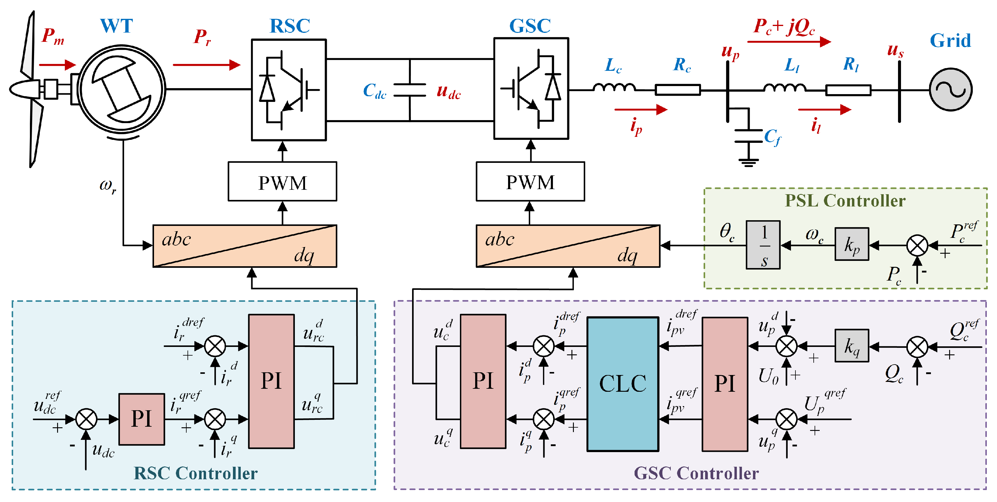
As shown in Figure 1, the PMSG-based wind turbine connects to an infinite bus via a transmission line . The system comprises a Rotor-Side Converter (RSC) and a Grid-Side Converter (GSC) linked by a DC capacitor.
      
    
    Figure 1.
      Basic structure of the Grid-Forming PMSG-based WT under PSL.
  
2.1. Rotor-Side Converter Control
The Rotor-Side Converter (RSC) is responsible for extracting mechanical power from the wind turbine and regulating the DC-link voltage. Inspired by the literature [], the electro-mechanical dynamics of the PMSG are described by the following swing equation


        where
        
- is the combined inertia constant of the wind turbine and generator.
 - is the generator rotor speed.
 - is the mechanical power captured from the wind.
 - is the active power extracted by the RSC.
 
The mechanical power is typically determined by a Maximum Power Point Tracking (MPPT) algorithm


        where  is the air density, A is the swept area of the turbine blades,  is the power coefficient, a function of tip speed ratio  and pitch angle , and  is the wind speed.
The outer control loop of the RSC regulates the DC-link voltage  to its reference  via a PI controller, generating the d-axis current reference  for active power control. For optimal efficiency, the q-axis current reference  is set to zero, minimizing generator losses. These references are tracked by fast inner current loops, which generate the required rotor voltage commands.
The DC-link capacitor serves as an energy buffer between the RSC and the GSC, with its voltage dynamics described by


        where  is the DC-link capacitance and  is the active power delivered to the grid.
For transient stability analysis, it is a standard simplification to assume that the DC-link voltage control is ideal, maintaining  at its reference  []. This implies that the power flowing from the RSC to the DC-link is instantaneously transferred to the GSC, such that . This assumption allows the analysis to focus on the synchronization dynamics of the GSC while still capturing the essential electro-mechanical coupling between the active power output and the kinetic energy of the wind turbine.
2.2. Grid-Side Converter Control
For analytical clarity, the following standard assumptions are made: (1) line resistances and PCC shunt capacitances are neglected; (2) inner current loop dynamics are considered much faster than the outer power loop. The validity of this simplified model for analytical purposes will be confirmed by full-dynamics simulations in Section 5.
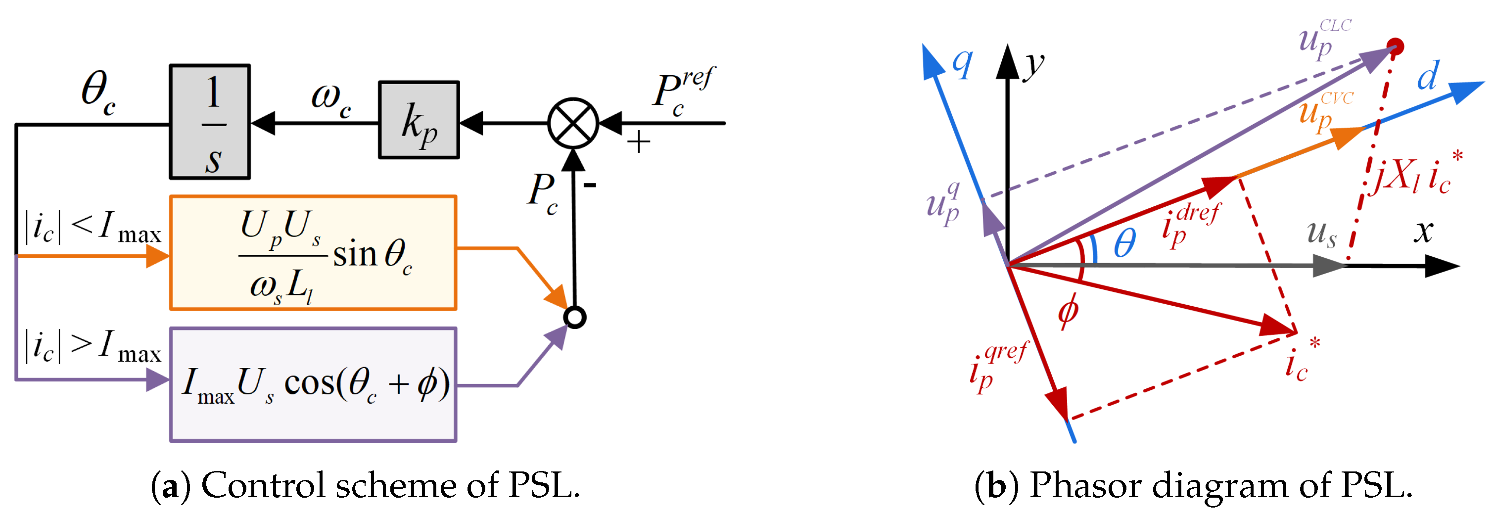
The GSC employs Power Synchronization Loop (PSL) control, as depicted in Figure 2a. The dynamic of the GSC is governed by the change in the converter angle  and its frequency  relative to the grid frequency  


        where  is the droop gain, and  and  are the reference and measured active power. The system switches between Constant Voltage Control (CVC) and Current Limiting Control (CLC) based on whether the output current magnitude exceeds the limit [].
      
    
    Figure 2.
      Control scheme and phasor diagram of PSL-GFM converter.
  
Constant Voltage Control (CVC) Mode: In CVC mode, the GSC functions as a voltage source. The outer voltage control loop regulates the PCC voltage aligned with the d-axis as the reference value  =  in ideal voltage control, generating the d-q axis current references (, ) for the inner current loops. The injected active and reactive power are


		The Stable Equilibrium Point (SEP) and an Unstable Equilibrium Point (UEP) in CVC mode are


Current Limiting Control (CLC) mode: During a fault, if the current reference magnitude from the voltage loop  exceeds the limit , the system switches to CLC mode. The relationship between the current references from the voltage loop and the saturated current is defined as


		In this mode, the GSC acts as a current source, and the saturated current vector is thus set to , as illustrated in the phasor diagram in Figure 2b. Further, according to Kirchhoff’s voltage law of the circuit, considering the relationship between PCC voltage, grid voltage, and line voltage drop, the PCC voltage  is


		In CLC mode, the active power is determined by the saturated current


		This mode introduces its own equilibrium points, which are dependent on the angle 


		The existence and location of these CLC equilibrium points depend on the saturated current angle , which is critical to the post-fault transient stability of the system.
3. Analysis of Transient Synchronization Stability
This section analyzes the transient stability of the PMSG-based system under the influence of current limiting and reactive power coupling.
3.1. Impact of the Saturated Current Angle on System Stability
The switching rule in Equation (8), based on the algebraic current magnitude, is not directly suitable for state-space stability analysis. To facilitate the analysis, this condition is converted into an equivalent one based on the state variable, the power angle . The system operates in CVC mode as long as the converter current  does not exceed the limit 


		This inequality defines the CVC operating region in terms of the angle 


		Thus, the system operates in CVC mode when  is within the switching boundaries , where . Outside this range, it enters CLC mode.
As illustrated in Figure 3, the system initially operating at the SEP (point A), experiences a fault at time . During the fault, its state follows the trajectory from D to E. Upon fault clearance at , the system’s subsequent behavior and ultimate stability depend crucially on the location of the CLC mode’s stable equilibrium point , which is relative to the saturated current angle .
      
    
    Figure 3.
      Illustration of system trajectories under different post-fault scenarios.
  
Under the assumption of , the rotor dynamics of the WT, described by Equation (1), are directly coupled to the electrical behavior of the GSC. During a fault interval from  to , the change in rotor kinetic energy and the deviation in the GSC angle are derived from Equations (1) and (4)


        where  and  are the rotor speeds at fault initiation and clearance, respectively, and  is the angle at clearance. Depending on the fault severity and the CLC parameter , the post-fault trajectory follows one of three critical scenarios, as illustrated in Figure 3.
3.1.1. Scenario 1: Recovery to the Original SEP in CVC Mode
For moderate faults, the system can return to its original SEP in CVC mode (point A). After the fault is cleared at , the system trajectory follows the path E → F → G → H → A, as depicted in Figure 3a. The recovery dynamics during the period from  to the final settling time  are governed by the change in the PSL angle and the rotor kinetic energy.
The total change in the PSL angle during recovery is provided by Equation (4)


          where  follows a piecewise profile through the CLC and CVC phases of recovery. Simultaneously, the change in rotor kinetic energy is described by


		  For a successful recovery, the final rotor speed  returns to its pre-fault value . Combining the energy dynamics during the fault Equation (14) and the recovery Equation (17) reveals the overall energy conservation principle for a stable transient event


		  This balance confirms that the net change in rotor kinetic energy is zero, as the energy gained during the fault is fully dissipated during the recovery phase.
3.1.2. Scenario 2: Trapping at the SEP in CLC Mode
During severe faults, which are removed after passing through the UEP (point B), the system will move to the right along the CLC curve. If the SEP in CLC mode (point C) is placed to the right of the switching line , the system will not switch to CVC but will stabilize at , as shown in Figure 3b. The system becomes trapped because the energy gained during the fault is insufficient to swing the angle back across the next period’s left switching boundary . In these cases, the system follows a trajectory similar to E → C, then


		  The shift from the original SEP  to the new one  injects a net potential energy into the system. Combining Equations (15) and (19), there is an energy difference 


		  This additional energy alters the system’s energy balance. The total change in rotor kinetic energy no longer sums to zero but is instead governed by


		  Since  is often positive and significant, especially for a small droop gain , it causes continuous rotor acceleration. Overspeed tripping occurs if the energy gain exceeds the rotor’s kinetic energy limit. The saturated current angle  directly determines  and thus the risk of this failure mode.
3.1.3. Scenario 3: Pole Slip to a Subsequent CVC SEP
As illustrated in Figure 3c, this occurs when the choice of  positions the CLC’s SEP (point C) in the CVC area such that the post-fault trajectory re-enters the CVC operating region along the path G-H, bypassing the CLC trap. It crosses the UEP  (point B) and switches to a subsequent CVC mode (G → H), finally settling at  (point A′).


		  This energy injection can cause rapid and severe rotor overspeed, as the kinetic energy absorbed by the rotor becomes substantial.


		  Because  is typically much larger than the potential energy change in Scenario 2, a pole slip poses a significant threat to the mechanical safety of the wind turbine. These scenarios highlight a key vulnerability: a fixed-angle CLC strategy can result in either trapping or pole slip, both leading to instability.
3.2. Effect of Reactive Power Control Loop
The reactive power control loop is essential for voltage regulation, which is defined as


        where  is the nominal voltage and  is the droop coefficient. Assuming  and substituting  from Equation (6),  becomes a function of the power angle .


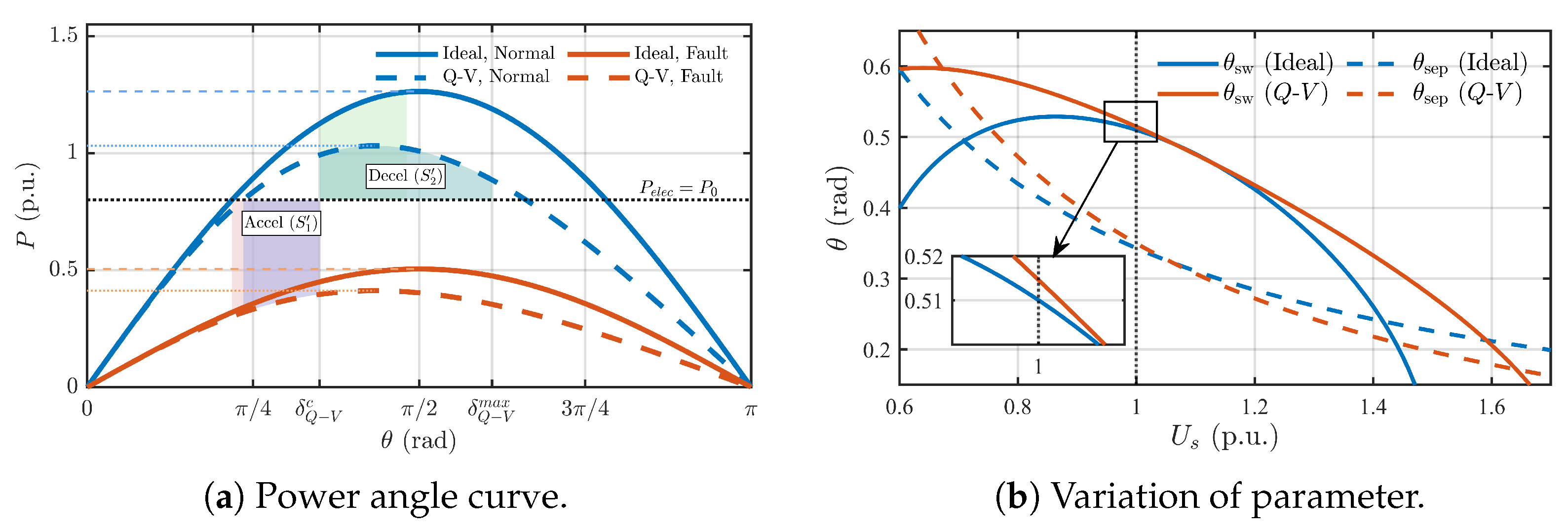
		This coupling alters the power-angle curve, as shown in Figure 4a. The active Q-V droop (dashed line) reduces the peak power transfer capability compared to the ideal case (solid line), thereby shrinking the system’s stability margin. The SEP in CVC mode, , is shifted to the right, as it is the solution to .
      
    
    Figure 4.
      The system dynamic behavior considering the effect of reactive power control loop.
  
Furthermore, the reactive power coupling affects the switching boundary  between CVC and CLC modes. From Equation (13),  is determined by


		Since  is a function of , this becomes a transcendental equation for  that must be solved numerically. As illustrated in Figure 4b, under nominal grid voltage , it slightly shifts  to a larger angle, expanding the CVC operating region . Moreover, this coupling implies that for a given set of parameters, a stable CVC operating point only exists within a critical grid voltage range . If  or , the system is forced to operate in CLC mode even under steady-state conditions, highlighting the significant impact of reactive power coupling on the system’s fundamental operating characteristics.
4. Transient Stability Enhancement Strategies
This section proposes a dual-mechanism enhancement strategy that combines an adaptive saturated current angle to eliminate detrimental CLC equilibrium points with a damping controller to ensure robust electro-mechanical stability.
4.1. Adaptive Saturated Current Angle for Stabilizing at Original SEP
To ensure the system returns to the original SEP in CVC mode post-fault, this section proposes an adaptive control strategy for the saturated current angle . Traditional CLC typically employs a fixed angle . As shown in Equation (10), this results in the active power output  being a nonlinear function of  and 


		This nonlinearity can lead to the formation of undesirable SEPs and UEPs within the CLC operating region, as defined by Equation (11). Such points can cause the WT to become locked in CLC mode or trip due to overspeed, particularly after severe AC faults, as depicted in Figure 3b,c. To eliminate these detrimental SEPs/UEPs in CLC mode, the proposed strategy redefines  to be dynamically dependent on . The control law for  is provided by


		When current limitation is active, the  axis current references for the inner loop,  and , are set according to


		Substituting  from Equation (28) into the general expression for  in Equation (10), the active power output under the proposed CLC becomes


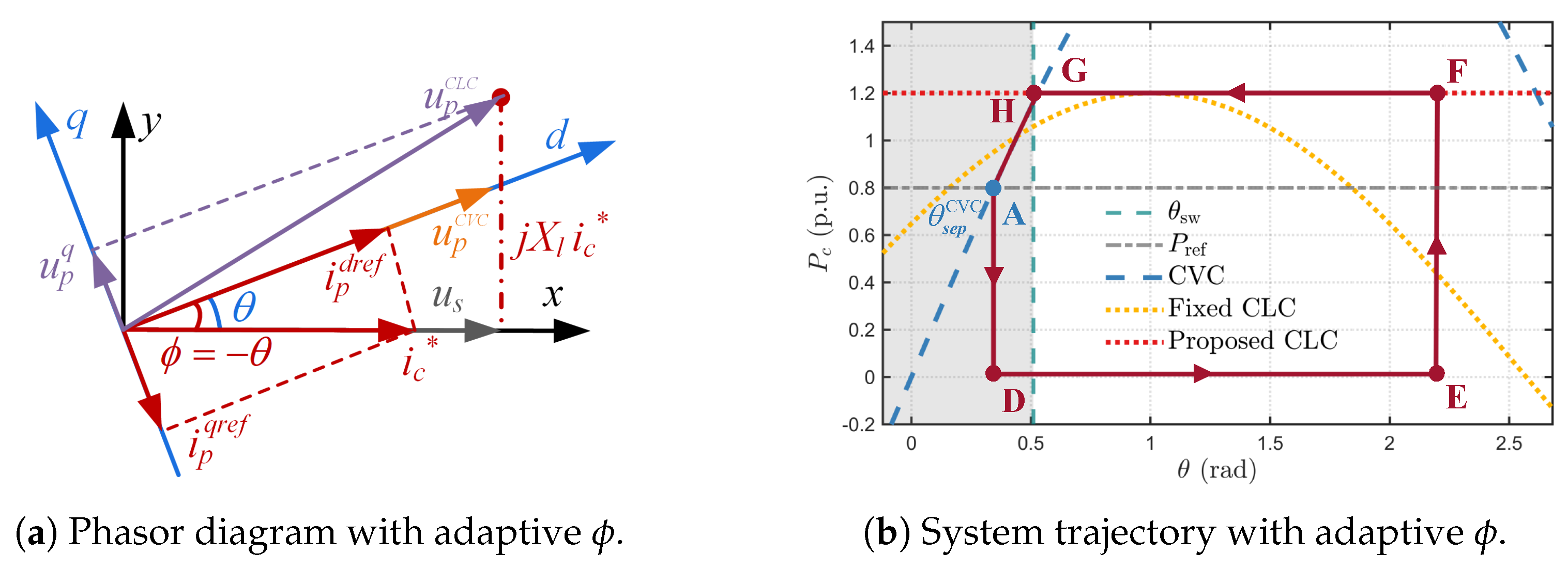
		With , the GSC active power in CLC mode  becomes , which represents the maximum active power transferable to the grid under the current limit , aligning the current vector with the grid voltage . This alignment is depicted in the phasor diagram in Figure 5a, where setting  forces the current vector  to align with the grid voltage , maximizing active power injection. The impact on the system’s power-angle characteristics is illustrated in Figure 5b. The power curve in CLC mode becomes a horizontal line at . Since this line does not intersect the power reference , assuming , the detrimental SEPs and UEPs of fixed-angle CLC are eliminated. Consequently, the post-fault system trajectory is guided back to the CVC operating region, ensuring a predictable and stable return to the original SEP and preventing the system from being trapped in CLC mode.
      
    
    Figure 5.
      Phasor diagram and system trajectory with the proposed adaptive  strategy.
  
The change in WT rotor kinetic energy and GSC power angle deviation during a fault interval () are provided by Equation (14) and Equation (15), respectively.


        where  is the rotor speed at fault clearance , typically the peak if the system recovers to its original SEP,  is the mechanical power, and  is the GSC active power output under fault voltage . With the proposed adaptive , the GSC fault power derived from Equation (30) is greater than conventional CLC with a fixed angle  from Equation (27)


		The inequality in Equation (33) highlights that the proposed CLC strategy maximizes active power injection during faults. According to Equations (31) and (32), a higher  translates to a smaller increase in rotor kinetic energy, thereby leading to a lower peak rotor speed .
Consequently, the proposed strategy is more effective in limiting turbine overspeed and power angle excursions. The fault recovery time  is the duration for which the system returns to the SEP in CVC mode after fault clearance. This recovery period can be divided into two intervals: the time spent in CLC mode until switching back to CVC mode , and the time spent in CVC mode until reaching the SEP . The durations are approximated by


		The proposed strategy increases  to , which is generally greater than  in conventional CLC. This larger  reduces the duration . Since  is primarily dependent on CVC mode dynamics and less affected by the preceding CLC strategy, the overall fault recovery time  is, consequently, reduced by the proposed adaptive  control.
4.2. Damping Enhancement Strategy via Adaptive Active Power Reference Regulation
To accelerate post-fault recovery and actively damp power angle oscillations, the control strategy is further enhanced by regulating the active power reference.
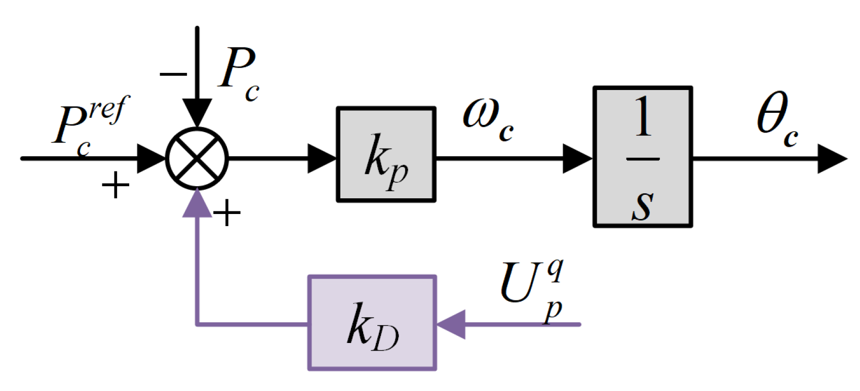
As illustrated in Figure 6, the active power reference is adaptively regulated by incorporating a damping signal. The modified reference  is defined as


        where  is the damping coefficient and  is the q-axis component of the PCC voltage. This regulation is dormant during normal operation since , but activates during transients. Substituting Equation (35) into the PSL governing equation modifies the system dynamics to


		During CLC mode, with the adaptive angle , the active power is  and the q-axis voltage  is derived from Equation (9) as . Substituting these into Equation (36) yields the complete dynamic equation under the enhanced control


		The damping term in Equation (37) introduces a state-dependent restoring force that opposes angle deviations, thus actively suppressing oscillations. To analyze its effect, the system dynamics are linearized around a transient operating point . The sensitivity of the angle’s rate of change to the angle itself, which indicates the system’s local stability, is expressed by


		For a small perturbation , the linearized dynamics from Equation (37) become


        where  is the effective synchronizing coefficient provided by the adaptive damping term


		For typical post-fault trajectories where the power angle  resides in the first quadrant (), the effective synchronizing coefficient  remains positive. This ensures that the damping term provides a restoring power proportional to the angle deviation, thereby enhancing system damping and accelerating post-fault recovery, as implied by the reduced recovery time  in Equation (34).
      
    
    Figure 6.
      Block diagram of the enhancement strategy.
  
Remark 1 (Extension to Multi-Generator Systems). 
The analysis in this paper uses a single-machine infinite-bus (SMIB) model to clearly analyze the fundamental instability mechanisms. Extending this strategy to multi-generator systems presents challenges, including inter-converter oscillations, the need for control coordination beyond the proposed local strategy, and system heterogeneity. Addressing these complexities is a key focus for future research.
5. Numerical Results
To validate the theoretical analysis and evaluate the performance of the proposed transient stability enhancement strategy, time-domain simulations are conducted on a PMSG-based wind turbine system model built in MATLAB/Simulink. The simulation parameters are summarized in Table 1.
       
    
    Table 1.
    Key simulation parameters.
  
5.1. Dynamic Response Analysis
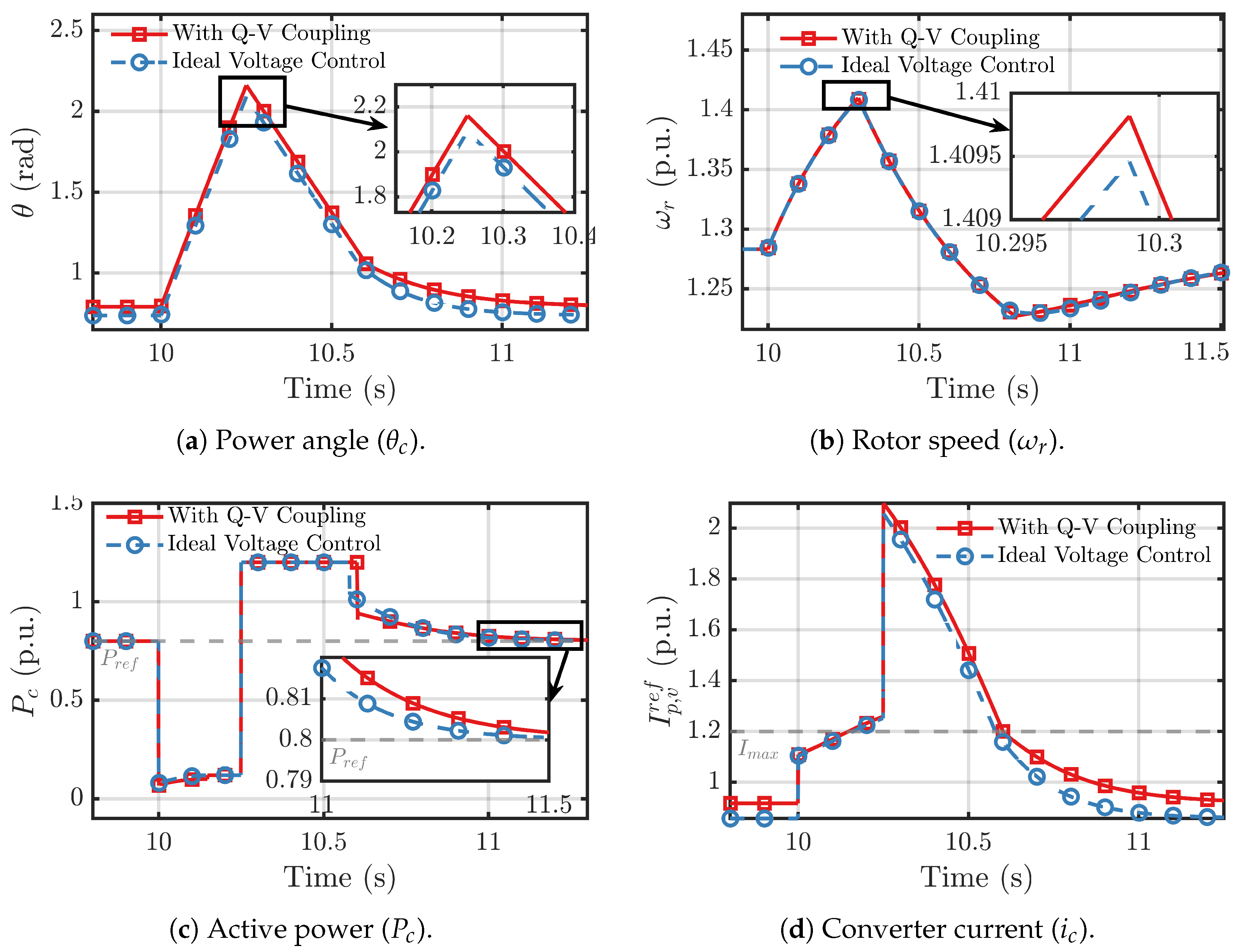
To validate the theoretical analysis of reactive power coupling, a three-phase fault is applied at the PCC at  s and cleared after 200 ms. Figure 7 compares the system’s dynamic response under ideal voltage control against the case with Q-V droop coupling. As shown in Figure 7a, with Q-V coupling active, the power angle  exhibits a larger peak overshoot and more pronounced post-fault oscillations. This confirms that reactive power coupling reduces the synchronizing torque, as analyzed in Section 3. Consequently, the rotor speed  reaches a higher peak, as shown in Figure 7b, and the active power  recovery is more oscillatory, as seen in Figure 7c. The converter current  hits the limit  in both scenarios, but the system with Q-V coupling shows a slower recovery from saturation, as depicted in Figure 7d. These results validate that the reactive power control loop can degrade transient stability by weakening the system’s ability to resynchronize after a disturbance.
      
    
    Figure 7.
      Dynamic responses illustrating the effect of reactive power coupling.
  
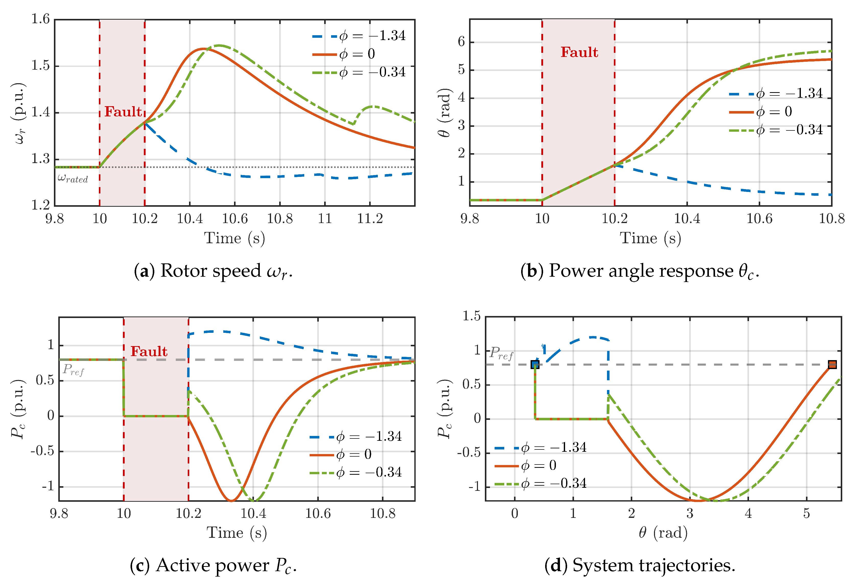
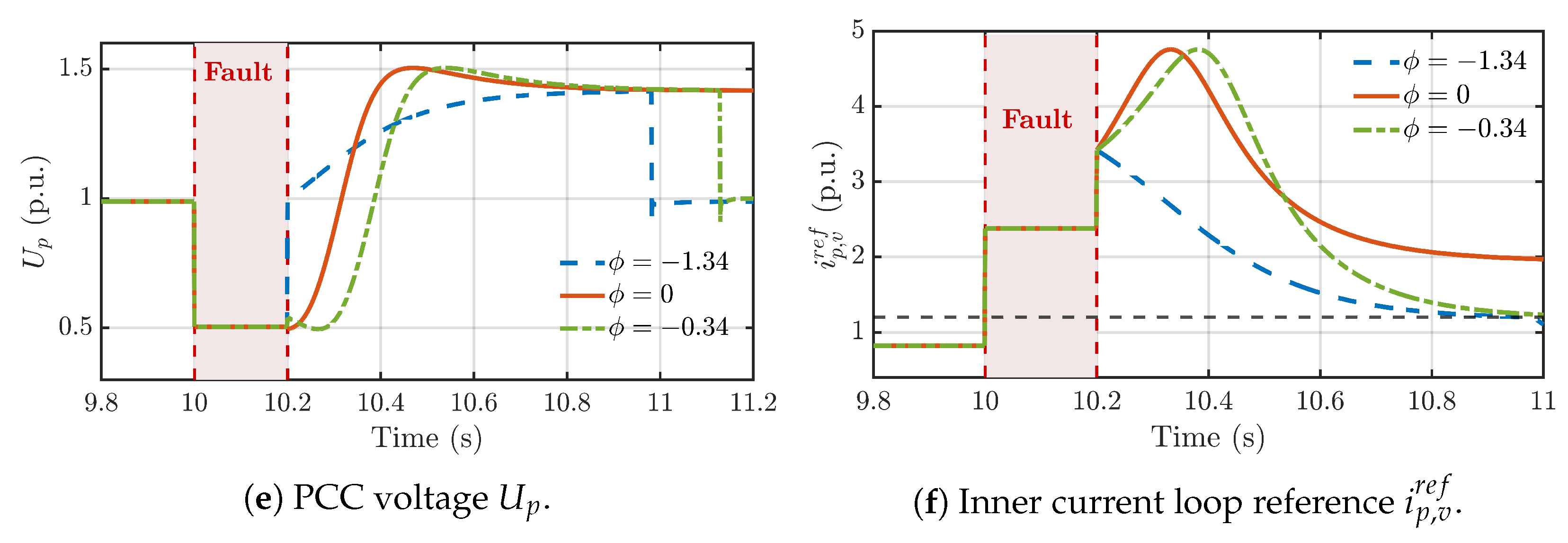
Next, the three post-fault dynamic scenarios predicted in Section 3 are validated by simulating a severe fault cleared after 200 ms with different fixed values for the saturated current angle . Before the fault, the key system parameters are calculated as  rad and  rad. For the system to stabilize in CVC mode post-fault, the CLC’s stable equilibrium point  must lie within the CVC region . This condition constrains the permissible range for  to  rad. Figure 8  provides simulation results that validate the three distinct post-fault scenarios predicted by the theoretical analysis in Section 3, with each scenario triggered by a different choice of the fixed saturated current angle :


    Figure 8.
      Validation of post-fault dynamic scenarios predicted in Section 3.
  
- Scenario 1 (Stable Recovery, rad): This angle lies within the safe operating range. As seen in the plots, after the fault is cleared, the rotor speed () peaks and then safely returns to its nominal value, while the power angle () successfully re-synchronizes to its original stable equilibrium point (SEP).
 - Scenario 2 (Trapped in CLC, rad): When is outside the safe range, the system becomes trapped at the CLC’s SEP. The trajectory plot (d) shows the system stabilizing on the CLC power curve. This creates a sustained energy imbalance, causing the rotor speed (a) to accelerate continuously until an overspeed trip would occur.
 - Scenario 3 (Pole Slip, rad): With an angle at the boundary of the safe range, the system avoids the CLC trap but undergoes a pole slip. The power angle (b) slips to a subsequent SEP near . This event injects a large amount of energy into the rotor, causing a rapid and severe over-acceleration seen in the rotor speed plot (a).
 
These results confirm that a fixed  creates a significant vulnerability, where the system can either get trapped or suffer a pole slip, both leading to instability. This motivates the need for the proposed adaptive control strategy.
5.2. Performance of the Proposed Adaptive Control Strategy
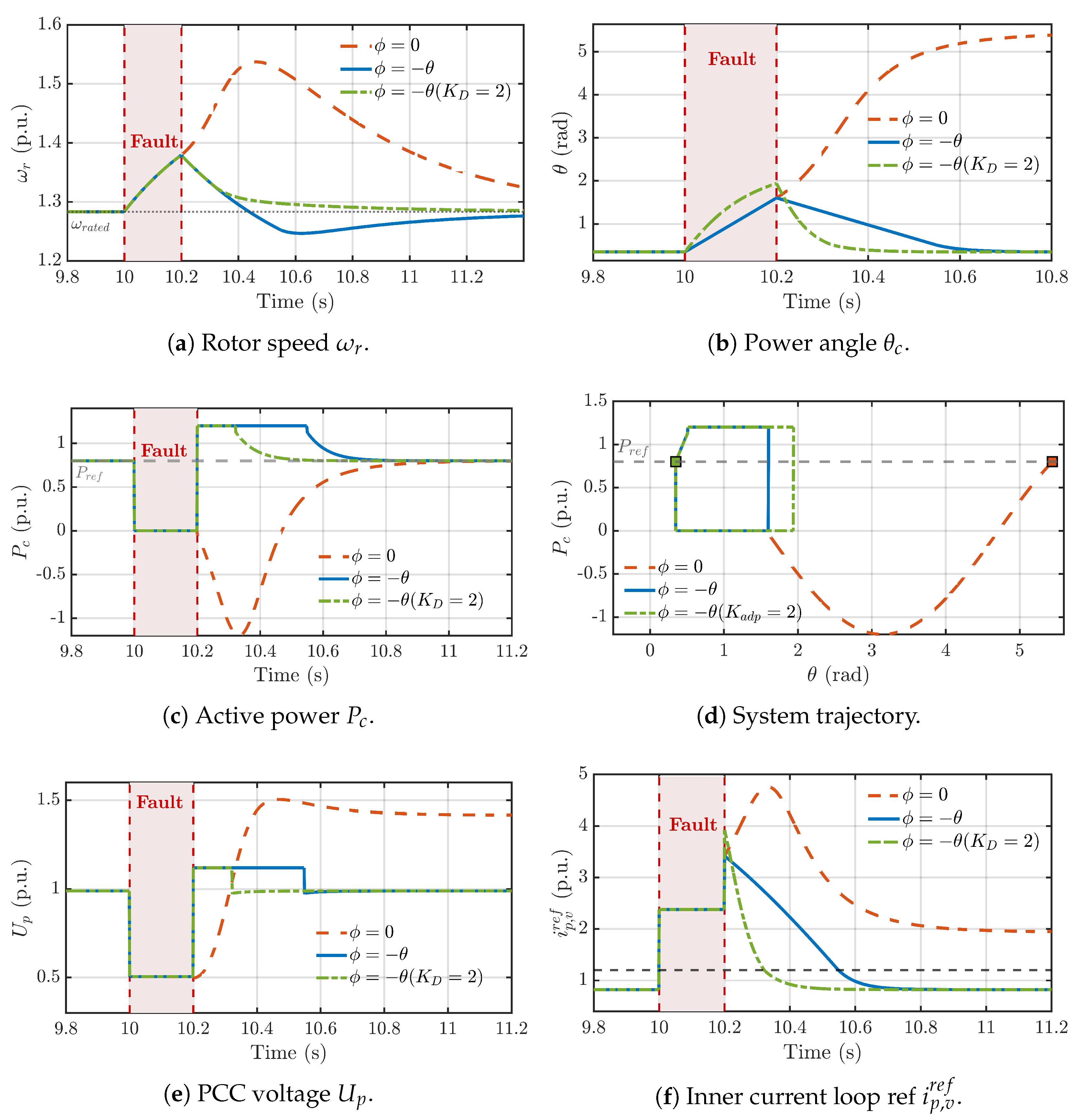
The performance of the proposed adaptive control strategy is evaluated under the same fault condition, using the controller gains (, ) specified in Table 1. Figure 9 compares the system response for the following three cases: (1) conventional CLC with a fixed angle , (2) the proposed adaptive angle  without damping enhancement, and (3) the full proposed strategy with adaptive angle and damping enhancement (). For this comparison, a damping gain of  was selected, as it provides a strong balance between fast recovery and first-swing overshoot, a trade-off explored further in Section 5.3.
      
    
    Figure 9.
      Performance of the proposed adaptive control strategy under fault conditions.
  
As shown in Figure 9a, the conventional strategy fails, with the rotor speed exceeding the trip threshold. In contrast, both versions of the proposed strategy maintain stability. The adaptive angle alone prevents CLC trapping and ensures recovery, while the full strategy with damping enhancement significantly reduces oscillations and accelerates the return to steady state. The system trajectory in Figure 9d clearly shows how the proposed strategy avoids the detrimental CLC equilibrium point and guides the system back to the original CVC SEP.
Table 2 provides a quantitative comparison using three Key Performance Indicators (KPIs): Peak Power Angle (PPA), Recovery Time (RT, time for  to settle within  of nominal), and Integral of Absolute Error (IAE) of the power angle. The proposed adaptive angle strategy significantly reduces the PPA compared to the unstable conventional case. The full strategy with adaptive damping achieves the fastest recovery time (0.174 s) and the lowest IAE (0.0916). It is noted that the introduction of the adaptive damping term creates a more aggressive restoring force, leading to a faster deceleration but also causing a slightly larger initial overshoot (PPA). This trade-off between first-swing magnitude and subsequent settling time is typical for damping control, and the overall result demonstrates superior performance in both stability margin and post-fault recovery speed.
       
    
    Table 2.
    Quantitative Performance Indicator (KPI) Comparison.
  
5.3. Discussion on Robustness and Parameter Tuning
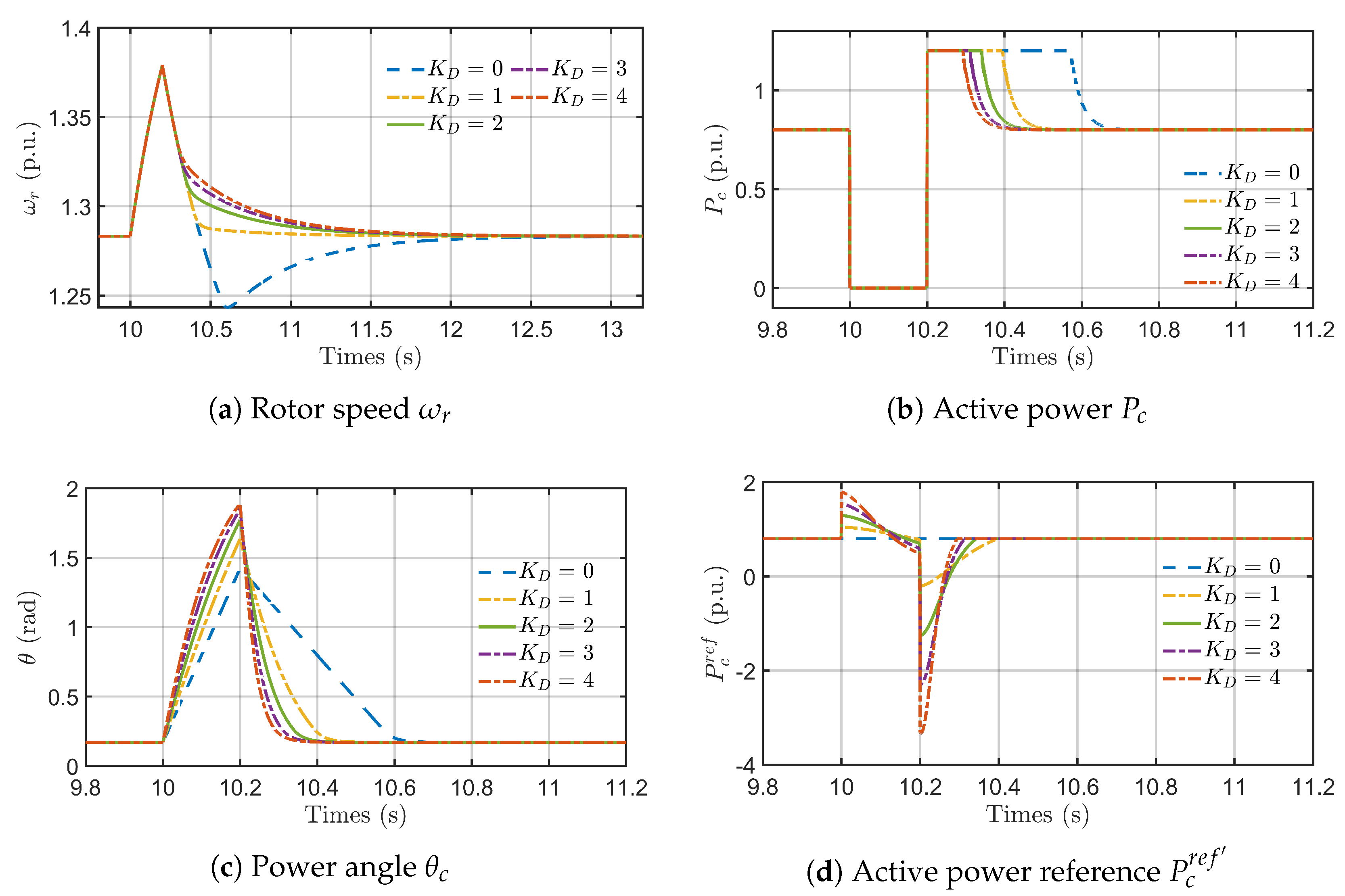
Finally, to validate the adaptive damping law and investigate the system’s sensitivity to the gain , a parameter scan was performed. The results, presented in Figure 10, reveal a critical trade-off inherent in the control design. As  increases, the adaptive control provides a more aggressive restoring force, which significantly reduces oscillation settling time in rotor speed, active power, and power angle, as shown in Figure 10a, Figure 10b and Figure 10c respectively. However, this improved damping comes at the cost of a larger initial power angle overshoot (PPA). For instance, increasing  from 0 to 4 raises the peak angle but progressively suppresses post-fault oscillations.
      
    
    Figure 10.
      Damping coefficient parameter scan results.
  
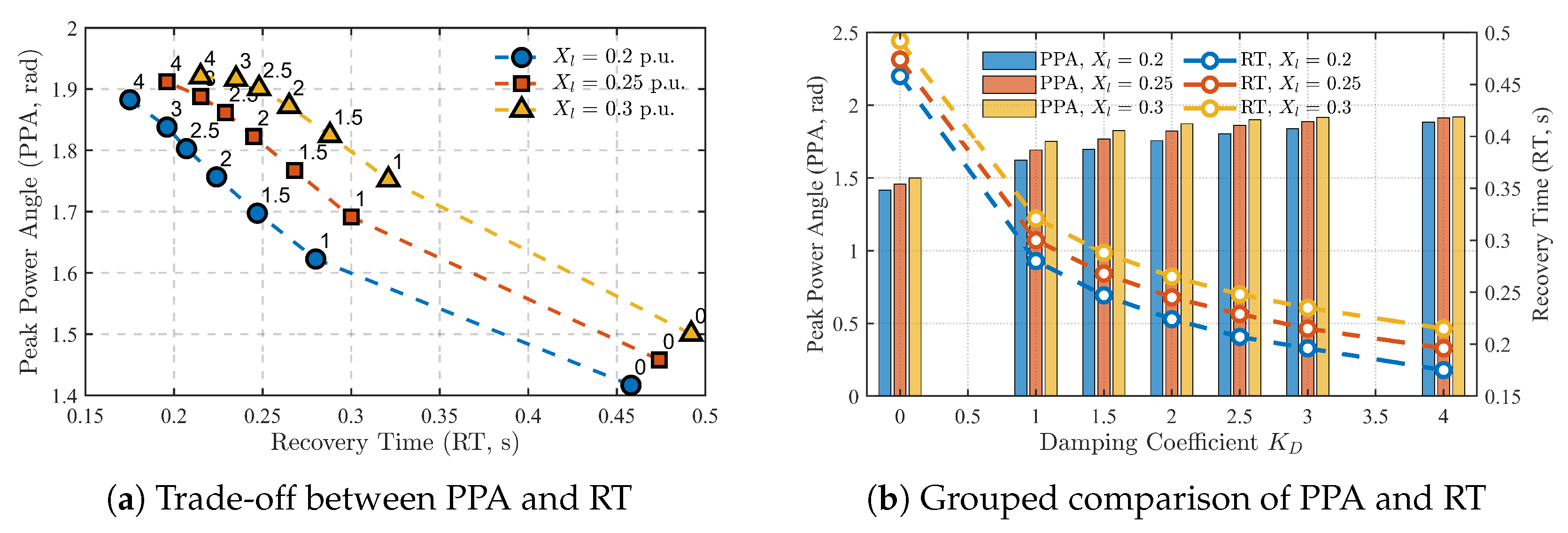
Table 3 quantifies this trade-off by comparing several Key Performance Indicators (KPIs). As the damping gain  increases, the Peak Power Angle (PPA) also increases, indicating a larger first swing. Conversely, the recovery time (RT) and the Integral of Absolute Error (IAE) generally decrease, signifying improved damping and faster settling. For instance, increasing  from 0 to 2 reduces the RT by over 62% to its minimum value of 0.174 s, but at the cost of a 24% increase in PPA. Further increasing  to 4.00 continues to reduce the IAE to its minimum, but the RT slightly increases, indicating that an overly aggressive gain can degrade some aspects of the recovery. This trend reveals a critical design trade-off that guides the tuning of the damping gain . Figure 11a shows that as the damping gain  increases, the RT decreases while the PPA increases, illustrating a clear trade-off. Figure 11b provides a grouped comparison, confirming that for various line reactances , a higher  consistently leads to a larger PPA and a shorter RT. The parameter scan was conducted under varying grid strengths ( = 0.2, 0.25, and 0.3 p.u.) to ensure the controller’s robustness. As shown in Figure 11, while weaker grids with higher  naturally lead to larger Peak Power Angles and longer recovery times, the proposed adaptive damping strategy consistently improves performance and ensures stability across all tested conditions. This confirms the controller’s effectiveness over a range of grid impedances.
       
    
    Table 3.
    Comprehensive Performance Indicator (KPI) Comparison Analysis.


    Figure 11.
      (a) Trade-off between Peak Power Angle (PPA) and recovery time (RT) for varying damping gain . (b) Grouped bar comparison of PPA and RT.
  
The selection process must balance the benefit of rapid damping against the need to maintain an adequate power angle stability margin. The objective is to find a gain that provides a reduction in recovery time without pushing the peak angle beyond its stability limit. The parameter scan validates this methodology, demonstrating that a moderate gain, such as , offers a robust solution, achieving effective damping without jeopardizing the overall system stability.
Furthermore, it is critical to address the sensitivity to the saturated current angle limit, a key parameter in conventional methods. A major contribution of the proposed adaptive control () is the elimination of this very sensitivity. Unlike fixed-angle strategies that risk instability if the chosen angle is suboptimal for given fault conditions, our approach dynamically adjusts the angle to guarantee a trajectory towards a stable post-fault equilibrium. This removes a significant tuning challenge and a major potential failure mode, thereby enhancing the controller’s intrinsic robustness.
A critical aspect for practical implementation is compliance with modern grid codes, which mandate that renewable energy sources must remain connected during voltage sags—a capability known as fault ride-through (FRT). The proposed control strategy directly addresses this requirement. By preventing pole-slipping instability and ensuring rapid, well-damped recovery from severe voltage dips, the controller ensures the PMSG system successfully ‘rides through’ the fault without disconnecting. The time-domain results presented in Figure 9, where the system endures a severe fault and returns to stable operation, serve as a clear demonstration of this FRT capability, aligning the controller’s performance with the objectives of grid codes for renewable-rich power systems.
6. Conclusions
This paper presented a comprehensive analysis of the transient stability challenges in PMSG-based GFM systems, highlighting the risks of CLC trapping and rotor overspeed caused by the interplay between current limiting and reactive power control. A dual-mechanism enhancement strategy was proposed to address these vulnerabilities. The strategy integrates an adaptive saturated current angle control, which eliminates detrimental CLC equilibrium points and maximizes active power injection during faults, with a damping controller that actively accelerates post-fault recovery. Simulation results confirmed that the proposed strategy effectively prevents instability, ensures reliable fault ride-through, and significantly improves the overall system stability and dynamic response.
However, this study is based on simulations, and its findings must be validated through experimental work to confirm real-world applicability. Practical implementation challenges, such as digital control delays, sensor noise, and the tuning trade-off of the damping gain, also warrant further study. Future work will focus on addressing these aspects, beginning with hardware-in-the-loop (HIL) experiments to validate the real-time performance of the proposed control strategy before progressing to prototype testing.
Author Contributions
Conceptualization, H.L., Y.Z. and Z.D.; methodology, H.L. and T.M.; software, H.L.; validation, H.L., T.M. and Y.Z.; formal analysis, T.M.; investigation, D.W.; resources, Y.Z.; data curation, D.W.; writing—original draft preparation, H.L.; writing—review and editing, T.M.; visualization, Y.Z.; supervision, Y.L. and Z.D.; project administration, Y.L. and Z.D.; funding acquisition, Z.D. All authors have read and agreed to the published version of the manuscript.
Funding
This work was supported by Smart Grid-National Science and Technology Major Project (2025ZD0807200).
Institutional Review Board Statement
Not applicable.
Informed Consent Statement
Not applicable.
Data Availability Statement
The original contributions presented in this study are included in the article. Further inquiries can be directed to the corresponding author.
Acknowledgments
The authors would like to thank Jia Hu and Jing Li of Guangzhou Power Supply Bureau of Guangdong Power Grid Co., Ltd. for their significant contributions during the manuscript revision. Their efforts in designing and conducting additional simulations to validate controller robustness, performing a detailed sensitivity analysis of the damping gain, and assisting with data processing and visualization were invaluable in addressing reviewer comments and enhancing the quality of this work.
Conflicts of Interest
The authors declare that the research was conducted in the absence of any commercial or financial relationships that could be construed as a potential conflict of interest. This work was supported by Smart Grid-National Science and Technology Major Project (2025ZD0807200). The funder was not involved in the study design, collection, analysis, interpretation of data, the writing of this article or the decision to submit it for publication.
Abbreviations
| Abbreviation | Description | 
| GFL | Grid-Following | 
| GFM | Grid-Forming | 
| CVC | Constant Voltage Control | 
| CLC | Current Limiting Control | 
| PMSG | Permanent Magnet Synchronous Generator | 
| SEP | Stable Equilibrium Point | 
| UEP | Unstable Equilibrium Point | 
| RSC | Rotor-Side Converter | 
| GSC | Grid-Side Converter | 
| MPPT | Maximum Power Point Tracking | 
| PSL | Power Synchronization Loop | 
| PCC | Point of Common Coupling | 
References
- Gu, Y.; Green, T. Power System Stability with a High Penetration of Inverter-Based Resources. Proc. IEEE 2023, 111, 832–853. [Google Scholar] [CrossRef]
 - Yadav, V.; Balasubramaniyan, S. Synchronization Stability and Control Strategies for PMSG-based Wind Energy Systems under Grid Fault Conditions. Energy Rep. 2025, 13, 6148–6160. [Google Scholar] [CrossRef]
 - Huang, L.; Xin, H.; Wang, Z.; Zhang, L.; Wu, K.; Hu, J. Transient Stability Analysis and Control Design of Droop-Controlled Voltage Source Converters Considering Current Limitation. IEEE Trans. Smart Grid 2019, 10, 578–591. [Google Scholar] [CrossRef]
 - Qoria, T.; Wang, X.; Kadri, R. Grid-Forming Control VSC-based Including Current Limitation and Re-Synchronization Functions to Deal with Symmetrical and Asymmetrical Faults. Electr. Power Syst. Res. 2023, 223, 109647. [Google Scholar] [CrossRef]
 - Zhang, L.; Harnefors, L.; Nee, H. Power-Synchronization Control of Grid-Connected Voltage-Source Converters. IEEE Trans. Power Syst. 2010, 25, 809–820. [Google Scholar] [CrossRef]
 - Qoria, T.; Gruson, F.; Colas, F.; Kestelyn, X.; Guillaud, X. Current Limiting Algorithms and Transient Stability Analysis of Grid-Forming VSCs. Electr. Power Syst. Res. 2020, 189, 106726. [Google Scholar] [CrossRef]
 - Shuai, Z.; Shen, C.; Liu, X.; Li, Z.; Shen, Z. Transient Angle Stability of Virtual Synchronous Generators Using Lyapunov’s Direct Method. IEEE Trans. Smart Grid 2019, 10, 4648–4661. [Google Scholar] [CrossRef]
 - Wang, Z.; Guo, L.; Li, X.; Wang, Z.; Wu, K.; Zhou, X.; Wang, C. Transient Stability Analysis of Multiparallel Grid-Forming Converters Considering Active and Reactive Power Control Coupling and Current Limiting. IEEE Trans. Power Electron. 2025, 40, 13615–13631. [Google Scholar] [CrossRef]
 - Li, X.; Tian, Z.; Zha, X.; Sun, P.; Hu, Y.; Huang, M. An Iterative Equal Area Criterion for Transient Stability Analysis of Grid-Tied Converter Systems with Varying Damping. IEEE Trans. Power Syst. 2024, 39, 1771–1784. [Google Scholar] [CrossRef]
 - Yan, J.; Shi, X.; Liu, T.; Wang, Z.; Zhang, L.; Lin, L. Weak Grid Characteristic Analysis and Operating Mode Selection for Voltage Support Enhancement of Wind Farms Connected to MMC-HVDC During Asymmetric Faults. IEEE J. Emerg. Sel. Top. Power Electron. 2025, 13, 2917–2927. [Google Scholar] [CrossRef]
 - Xie, H.; Yao, J.; He, W.; Yang, D.; Gong, S.; Zhao, L. Transient Stability Analysis and Improved Control Strategy of PMSG-based Grid-forming Wind Energy Conversion System Under Symmetrical Grid Fault. J. Mod. Power Syst. Clean Energy 2025, 13, 128–141. [Google Scholar] [CrossRef]
 - Si, W.; Fang, J.; Chen, X.; Xu, T.; Goetz, S. Transient Angle and Voltage Stability of Grid-Forming Converters with Typical Reactive Power Control Schemes. IEEE J. Emerg. Sel. Top. Power Electron. 2024, 13, 2917–2927. [Google Scholar] [CrossRef]
 - Yang, M.; Wang, Y.; Guerrero, J. Impact of Reactive Power Control on Low-Frequency Oscillation of Virtual Synchronous Generators. IEEE Trans. Power Syst. 2025, 40, 3604–3607. [Google Scholar] [CrossRef]
 - Liu, Y.; Zhu, L.; Xu, X.; Li, D.; Liang, Z.; Ye, N. Transient Synchronization Stability in Grid-Following Converters: Mechanistic Insights and Technological Prospects—A Review. Energies 2025, 18, 1975. [Google Scholar] [CrossRef]
 - Lu, Y.; Li, Y.; Mu, T.; Shao, C.; Liu, J.; Yang, D.; Du, Z. Segmental Equal Area Criterion for Grid Forming Converter with Current Saturation. Int. J. Electr. Power Energy Syst. 2024, 159, 110015. [Google Scholar] [CrossRef]
 - Hu, M.; Su, M.; Yuan, L.; Chen, S.; Dong, Z. Analysis and Enhancement of Transient Synchronization Stability for Grid-Connected VSG Considering Reactive Power Coupling and Fault Current Limitation. IEEE J. Emerg. Sel. Top. Ind. Electron. 2025, 6, 1153–1165. [Google Scholar] [CrossRef]
 - Xin, H.; Huang, L.; Zhang, L.; Wang, Z.; Hu, J. Synchronous Instability Mechanism of P-f Droop-Controlled Voltage Source Converter Caused by Current Saturation. IEEE Trans. Power Syst. 2016, 31, 5206–5207. [Google Scholar] [CrossRef]
 - Qoria, T.; Wu, H.; Wang, X.; Colak, I. Variable Virtual Impedance-Based Overcurrent Protection for Grid-Forming Inverters: Small-Signal, Large-Signal Analysis and Improvement. IEEE Trans. Smart Grid 2023, 14, 3324–3336. [Google Scholar] [CrossRef]
 - Orihara, D.; Taoka, H.; Kikusato, H.; Hashimoto, J.; Otani, K.; Khaliqur, R.; Ustun, T. Theoretical Comparison of Current Limiting Algorithms in Grid-Forming Inverter in Terms of Transient Stability. IEEE Open J. Power Electron. 2025, 6, 109–119. [Google Scholar] [CrossRef]
 - Fan, B.; Wang, X. Equivalent Circuit Model of Grid-Forming Converters with Circular Current Limiter for Transient Stability Analysis. IEEE Trans. Power Syst. 2022, 37, 3141–3144. [Google Scholar] [CrossRef]
 - Wang, K.; Song, Q.; Liu, W.; Zhao, B.; Zhang, P. Reactive Power Characteristics and FRT Strategy for Grid-Forming Converters with Virtual Impedance-Based Current Limiting. IEEE Trans. Energy Convers. 2025, 40, 1165–1177. [Google Scholar] [CrossRef]
 - Arjomandi-Nezhad, A.; Guo, Y.; Pal, B.; Yang, G. Modeling Fault Recovery and Transient Stability of Grid-Forming Converters Equipped with Current Reference Limitation. IEEE Trans. Energy Convers. 2025, 40, 1140–1152. [Google Scholar] [CrossRef]
 - Li, Y.; Lu, Y.; Yang, J.; Yuan, X.; Yang, R.; Yang, S.; Ye, H.; Du, Z. Transient Stability of Power Synchronization Loop Based Grid Forming Converter. IEEE Trans. Energy Convers. 2023, 38, 2843–2859. [Google Scholar] [CrossRef]
 - Wu, H.; Wang, X. Design-Oriented Transient Stability Analysis of Grid-Connected Converters with Power Synchronization Control. IEEE Trans. Ind. Electron. 2019, 66, 6473–6482. [Google Scholar] [CrossRef]
 - Ghosh, S.; Bakhshizadeh, M.; Yang, G.; Kocewiak, Ł.; Pal, B.; Nadarajah, M. Nonlinear Stability Investigation of Type-4 Wind Turbines with Non-Autonomous Behavior Based on Transient Damping Characteristics. IEEE Access 2023, 11, 76059–76070. [Google Scholar] [CrossRef]
 - Lyu, X.; Du, W.; Mohiuddin, S.; Cheng, Y. Critical Clearing Time for Droop-Controlled Grid-Forming Inverters with Circular Current Limiting and Virtual Impedance Current Limiting. IEEE Trans. Power Syst. 2025, 40, 1997–2000. [Google Scholar] [CrossRef]
 - Wang, G.; Fu, L.; Hu, Q.; Liu, C.; Ma, Y. Transient Synchronization Stability of Grid-Forming Converter During Grid Fault Considering Transient Switched Operation Mode. IEEE Trans. Sustain. Energy 2023, 14, 1504–1515. [Google Scholar] [CrossRef]
 - Baeckeland, N.; Yang, B.; Seo, G. Transient Stability-Enhancing Method for Grid-Forming Inverters Under Current Limiting. IEEE Trans. Power Electron. 2025, 40, 6714–6725. [Google Scholar] [CrossRef]
 - Ge, P.; Liu, N.; Xu, H.; Mao, R.; Yang, Y. Transient Stability Enhancement Control for VSG Considering Fault Current Limitation and Reactive Power Support Constraints. IEEE Trans. Energy Convers. 2024, 40, 2599–2609. [Google Scholar] [CrossRef]
 - Zhang, Y.; Zhan, M. Transient Synchronous Stability Analysis of PMSG Grid-Connected System Considering Transient Switching Control Under Severe Faults. IEEE Trans. Power Electron. 2025, 40, 7298–7314. [Google Scholar] [CrossRef]
 - Bounadja, E.; Yahdou, A.; Kacemi, W.M.; Belhadj Djilali, A.; Benbouhenni, H.; Iqbal, A. A New Third-Order Continuous Sliding Mode Speed and DC-Link Voltage Controllers for a PMSG-based Wind Turbine with Energy Storage System. Arab. J. Sci. Eng. 2025, 50, 6017–6036. [Google Scholar] [CrossRef]
 - Gbadega, P.A.; Balogun, O.A. Modeling and Control of Grid-Connected Solar-Wind Hybrid Micro-Grid System with Multiple-Input Ćuk DC-DC Converter for Household & High Power Applications. Int. J. Eng. Res. Afr. 2022, 58, 191–224. [Google Scholar]
 - Yang, D.; Hu, T.; Zheng, T.; Qian, M.; Li, C.; Cao, Z.; Yan, G. Enhanced Dynamic Support Strategies of Grid-Forming-PMSG Based on DC-voltagesynchronization: Frequency and Q Support Perspective. Int. J. Electr. Power Energy Syst. 2025, 169, 110745. [Google Scholar] [CrossRef]
 - Gao, Z.; Du, W.; Zhao, T.; Xie, H.; Wang, H.; Yi, S. Transient Synchronization Stability Analysis of a Grid-Connected Wind Farm with Multiple PMSGs. IEEE Trans. Power Syst. 2024, 39, 6934–6947. [Google Scholar] [CrossRef]
 
Disclaimer/Publisher’s Note: The statements, opinions and data contained in all publications are solely those of the individual author(s) and contributor(s) and not of MDPI and/or the editor(s). MDPI and/or the editor(s) disclaim responsibility for any injury to people or property resulting from any ideas, methods, instructions or products referred to in the content.  | 
© 2025 by the authors. Licensee MDPI, Basel, Switzerland. This article is an open access article distributed under the terms and conditions of the Creative Commons Attribution (CC BY) license (https://creativecommons.org/licenses/by/4.0/).