Article

Effect of High Percentages of Coated Recycled Aggregates on the Flexural Behavior of Reinforced Concrete Beams

Department of Civil Engineering, Universidad de La Frontera, Temuco 4811230, Chile
*
Author to whom correspondence should be addressed.
Appl. Sci. 2025, 15(2), 829; https://doi.org/10.3390/app15020829
Submission received: 21 November 2024 / Revised: 21 December 2024 / Accepted: 8 January 2025 / Published: 16 January 2025

Abstract

:
Currently, the use of recycled aggregates (RA) in new concrete is allowed by several international regulations, although their replacement is limited to low percentages of the coarse fraction. In order to increase the percentage of RA, several authors have studied different processes to improve the microstructure of its surface. Therefore, it is necessary to analyze whether the current standards simulate the structural behavior of concretes with high percentages of RA. For this purpose, beams with 0%, 50% and 100% RA replacement coated with recycled binder paste (RBP) were made and their behavior was compared with the equations of the Eurocode 2 and ACI 318-19 code. As a result, we found that when 100% coated RA was used, the reduction in compressive strength was only 12.73%, with similar cracking patterns observed in RA beams across all series. In addition, the load capacity of the beams with RA was higher than the theoretical values provided by the codes. Finally, the experimental critical deflection was higher than that calculated by the code equations. Thus, it is recommended that these higher deflections be taken into account at the time of design.

1. Introduction

Over time, the fundamental mission of engineers has been to create safe, strong, and resource-efficient structures. However, this goal has been complicated by the need to integrate new materials, methods, and technologies that can ensure the sustainability (i.e., economic, environmental and social) of building projects in a society with limited natural resources [1,2].
In this context, sustainability refers to meeting today’s societal needs without endangering future generations, guaranteeing a balance between economic, social, cultural, and environmental aspects [3]. The amount of waste generated in construction by the demolition of existing buildings is considerable [4,5]. This increasing waste production represents a major challenge in many developing cities, which are experiencing remarkable growth due to increasing urban population and widespread urban development projects [6,7]. Globally, 35% of all solid waste is made up of construction and demolition waste (CDW) [8], with more than 80% of this waste corresponding to concrete rubble, bricks, tiles, decorative materials, dust, and other materials used in construction [9].
With over 25 billion tons produced each year, concrete is the most frequently used building material in the world [10]. The volume of concrete comprises 70% to 80% aggregates, and in 2023 the estimated extraction of natural aggregates (NA) for use in concrete worldwide was close to 47.5 billion tons [11,12]. This is one of the reasons that has led to a shortage of natural aggregates around the world [13,14], posing a major challenge for future generations if natural resource consumption continues at the current rate. In addition, there has been growing concern regarding the environmental repercussions of concrete production, primarily related to cement, as it is thought to be the source of about 90% of concrete’s CO2 emissions [15,16,17].
Consequently, a significant amount of empirical research has been undertaken recently with the aim of alleviating the negative environmental effects related to the production and utilization of concrete. One strategy involves the valorization of various CDW types, with recycled concrete aggregates (RCA) being extensively studied due to their properties and characteristics [7,18]. Therefore, the primary goal is to diminish the utilization of natural aggregates alongside the amount of waste sent to landfill sites [19].
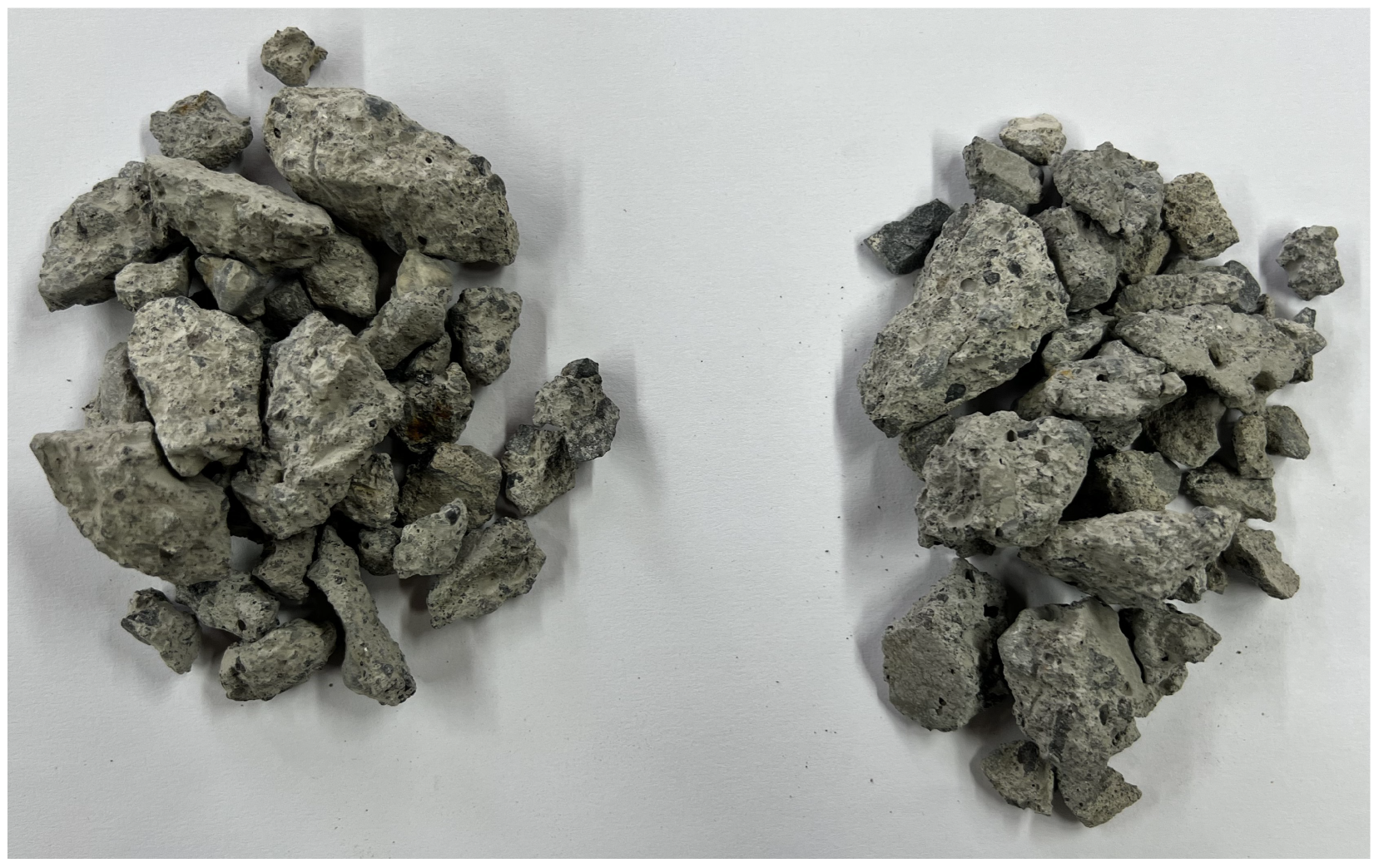
There are clear differences between recycled and natural aggregates; for example, the former has a rough and porous surface texture resulting from the residual mortar attached to the particles of the aggregate. The properties of recycled aggregates (RA) are influenced by the characteristics of the source materials as well as by the characteristics of the concrete from which they are derived. Recycled aggregates exhibit a significant increase in water absorption capacity, which is their main difference with to natural aggregates. These differences can cause modifications in both the fresh and hardened state when using RA to manufacture concrete [20]. In general, the partial or complete substitution of recycled aggregates in the concrete composition results in lower mechanical performance than for concrete made entirely from natural aggregates [21,22]. Replacing NA with RA can reduce concrete strength by up to 40%, and can also cause a decrease in other key properties [17]. For this reason, several studies are currently analyzing ways to improve recycled aggregates to maximize their use and reduce their impact on new concrete [23,24,25].
Despite this effect, the structural performance of reinforced concrete with RA is not clearly evident, as the flexural behavior is primarily influenced by the incorporation of steel reinforcement [26]. Research into the use of recycled concrete aggregates has progressed in both unreinforced and reinforced concrete applications [27,28]. Studies of the structural performance and economic aspects of using recycled aggregate concrete elements in nonstructural elements shows that RA can be considered a reliable material for use in structural elements provided that it is properly applied [29].
This trend has led to the development of specific regulations in several countries that control and promote the use of recycled aggregates as either a partial or complete substitute for natural aggregates. However, current regulations governing the use of RAs in concrete mostly limit their use to low replacement percentages. Therefore, it is necessary to look for processes that can improve the properties of RAs to increase the percentages of use without significantly affecting the properties of new concretes. The objective of this study was to analyze the behavior of coarse recycled aggregate (CRA) with an improvement process (i.e., coating with recycled binder paste, RBP) and verify the feasibility of using RAs in high percentages in reinforced concrete beams. The tested beams were designed using different percentages of treated RA. In addition, the load-deflection response, critical and end moments, load capacity, and critical and end strains of the beams were studied by evaluating the extent to which the provisions of existing codes such as ACI 318-19 and the Eurocode 2 predict the aforementioned characteristics. By providing a comparison with experimental results, this research can promote the use of recycled aggregates in structural projects.

2. Materials and Methods

2.1. Materials

2.1.1. Cement

The cement utilized to make the beams consisted of clinker, pozzolan, and gypsum. According to ASTM C595M [30], this cement, also known as Portland–pozzolan cement, is categorized as type IP. According to its technical data sheet, it has an initial setting time of 180 min and a final setting time of 240 min. It has a specific weight of 2.81 g / cm 3 and a Blaine-specific surface area of 4100 cm 2 / g . The SO3 content is 2.4%. In regard to its mechanical properties, it has a compressive strength of 22.6 MPa and a tensile strength of 4.4 MPa at 7 days, while at 28 days these increase to 33.3 MPa and 6.1 MPa, respectively.

2.1.2. Aggregates

The natural and recycled aggregates came from local companies linked to the construction sector. The physical properties of the aggregates are detailed in Table 1. The natural aggregate was of siliceous origin. The recycled aggregate was of low quality, derived from aggregate processing of precast concrete fence wall debris with a compressive strength of design of 30 MPa, and was subsequently treated to improve its properties. The coarse recycled aggregate used to replace the natural aggregate had a particle size of 4.75–12.5 mm. The particle size distribution for the two aggregates is shown in Figure 1, while Figure 2 shows the uncoated and coated coarse recycled aggregate. In addition, for treatment of the recycled aggregate, the fine fraction of the waste from the concrete fence walls was manually sieved using a 45 μ m sieve (No. 325) to obtain the recycled binder paste (RBP).
It is important to note that because of the attached mortar, the recycled aggregate had an old interfacial transition zone (ITZ), which causes a weak zone due to continuous cracking caused by the crushing process of the RA [31]. Even though the amount of ITZ is low, it represents a weak and porous region, which is a characteristic of recycled aggregates [32]. The multiple cracks on the ITZ may be related to porosity and water absorption associated with the origin of the recycled aggregates [31]. As mentioned above, because the recycled aggregate is of low quality, coming from the demolition of precast concrete fences, it is more porous; thus, it was treated to reduce its porosity and improve its water absorption.

2.1.3. Reinforcing Steel Bars

The quality of the reinforcing steel used for the beams was A630-420H, according to the Chilean standard NCh204.Of2006 [33]. The longitudinal reinforcement consisted of two superior bars of 8 mm diameter and two inferior bars of 16 mm diameter, while stirrups of 8 mm diameter were used for the transverse reinforcement.

2.1.4. Superplasticizer (SP)

A superplasticizer (SP) admixture was used to enhance the workability of the fresh concrete in order to maintain a similar slump without adding a significant volume of extra water and consequently raising the w/c ratio. The SP had a density of 1.2 kg/L and a solids concentration of 37%, and was incorporated at a concentration of 2% by weight of cement into the mixing water, which is the maximum allowed in accordance with its technical data sheet. In addition, to obtain the required fluid consistency, the fine aggregate content needed to be increased by 10%; this adjustment was carried out to offset the decrease in water content and maintain the homogeneity of the mixture, which is reflected in the mixture proportions presented in Table 2.

2.2. Mixing Ratio

Three distinct types of coarse aggregate were employed to produce G30 concretes. For all series, natural sand was utilized as the fine aggregate. A control series (N100) composed only of natural aggregates along with two series with a substitution by weight of 50% (CR50) and 100% (CR100) of coated recycled aggregate were produced for the cylindrical and prismatic test specimens and beams. The mixing ratios of each series are specified in Table 2. It is important to note that because of the increased porosity and water absorption of the RAs, the w/c ratio had to be raised in order to maintain the desired workability and satisfy the requirements of industrial usage.

2.3. Treatment

The improvement process consisted of coating the coarse recycled aggregate particles (C-CRA) with the recycled binder paste (RBP) to strengthen the bonded mortar, reduce its porosity and decrease the resulting water absorption. The mixture was prepared with 45% RCA by weight combined with a slurry of RBP and water in a ratio of 1:2. To ensure homogeneous conditions, the CRA was submerged in the slurry and agitated periodically for 6 h, then subjected to a gradual drying process in an oven at 35 °C for 40 h. The surplus paste was removed through a washing process and subsequently dried at 100 °C for storage under controlled conditions until the required quantity was obtained for manufacturing the concrete specimens. Given the properties of RBP, we expected very low pozzolanic activity limited to unreacted particles in the original concrete [34].

2.4. Beam Details

Three types of beams were prepared: control (N100), 50% replacement (CR50), and 100% replacement (CR100), each with dimensions of 150 mm × 300 mm × 2000 mm. The beam geometry, reinforcement, and load details are shown in Figure 3a. The longitudinal reinforcement of the beams consisted of 2 Φ 8 mm superior steel bars and 2 Φ 16 mm inferior steel bars. In addition, Φ 8 mm stirrups evenly spaced at 150 mm were used for the transverse reinforcement. In order to ensure adequate protection for the steel reinforcement bars, a continuous 25 mm cover was kept on all sides of the beams.

2.5. Test Configuration

A four-point load frame was used to test the beams. These were supported on steel bars fixedly located 100 mm from the edge of each side, as shown in Figure 3b. Two symmetrically concentrated loads were applied at the boundaries of the central third of the beams during the tests. The load from the frame shank was distributed using a steel beam, ensuring that each load was applied at a distance of 300 mm from the center of the beam. A free distance between supports of 1800 mm was maintained. The load was increased at a constant rate of ~3 kN/s, where the strains were recorded with a digital dial indicator at the center of the bottom edge of the beam. To determine the load, the average of the values obtained from the slope in the linear range of the control beams were used, specifically up to the yielding point, which corresponds to values documented in the literature [35]. Measurements of the applied load and generated strains were recorded in the Winlog Pro software (v.3.02.05) used by the frame. Crack propagation was monitored and marked at the end of the test.

3. Results

3.1. Mechanical Properties of Concrete

The compressive strength and modulus of elasticity of the series were obtained by testing three cylindrical specimens per series of Φ 150 mm × 300 mm after 28 days of curing according to ASTM C39/C39M-21 [36] and ASTM C469/C469M-14 [
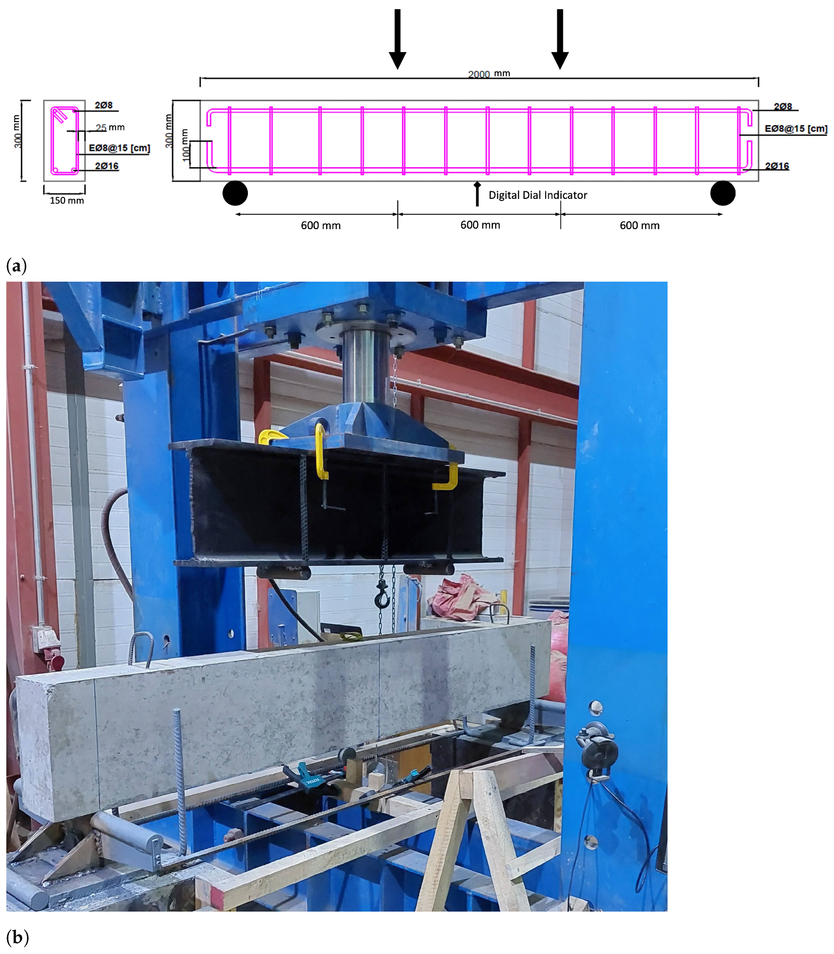
37], respectively. Assessment of the flexural strength was conducted on prismatic specimens with dimensions of 150 mm × 150 mm × 550 mm with a curing period of 28 days, employing the third-point loading methodology with a four-point flexural test loading frame in accordance with ASTM C78/C78M-18 [38]. The loads were applied to the edges of the central third of the prismatic specimens.
It is worth noting that the strength of recycled aggregate concrete generally exhibits a reduction in comparison to natural aggregate concrete [23]. This reduction in strength is primarily attributed to the presence of old mortar attached to to the surface of the RA, resulting in a porous layer that increases water absorption and results in a lower density, leading to a decrease in mechanical properties [13].
Therefore, the modulus of elasticity decreases when increasing the percentage of substitution of recycled aggregate [39]. This is evident from the results obtained in Table 3, where the series with only natural aggregates exhibits the highest modulus of elasticity among the specimens compared to the series using recycled aggregates.
After 28 days, the control series achieved the specified design strength of 30 MPa. In contrast, for the series containing recycled aggregates, an increase in the substitution percentage resulted in a reduction in the compressive strength of the concrete, indicating a negative relationship between the percentage of RA replacement and the compressive strength Kwan et al. [40].

3.2. Beam Behavior—Experimental Results

3.2.1. Cracking Pattern and Mode of Failure

Figure 4 shows the cracking pattern of the beams tested at 28 days for the N100, CR50, and CR100 series. These cracks were marked and numbered at the end of the test and their length and thickness dimensions were recorded. All tested beams showed a similar failure pattern and number of cracks; vertical cracks were first generated within the central third, which is associated with flexural bending developing from the lower part of the beam towards the compression zone [41]. During the last part of the test, diagonal cracks associated with shear failure formed, and tended to be more diagonal in shape as they grew further away from the central third [19].

3.2.2. Load–Strain

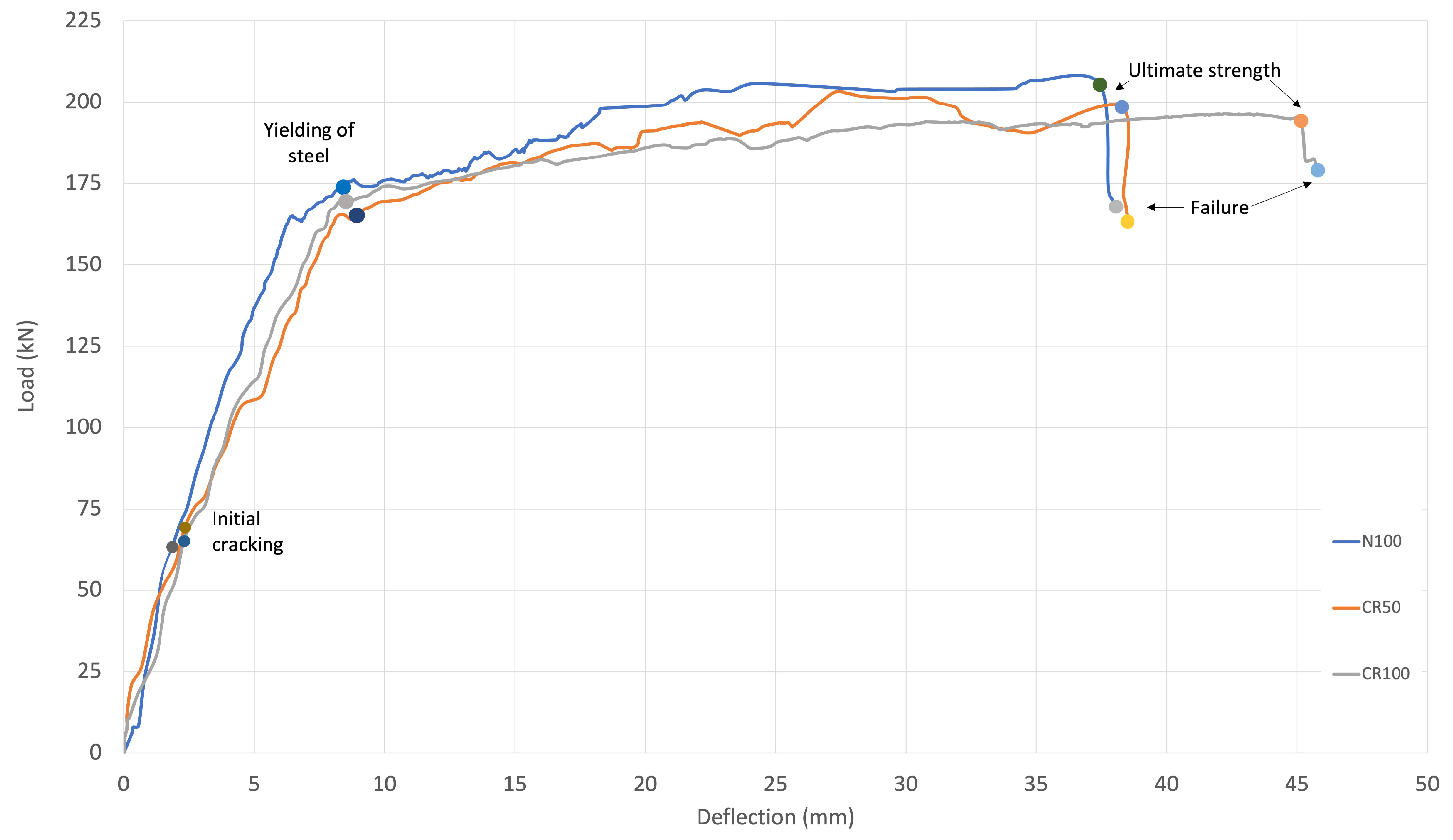
Figure 5 provides information on how the strains and load in the concrete vary in relation to the concrete mix for the different series tested at 28 days. The curves start with a steep slope until the appearance of flexural cracks in the central third of the beams, after which the slopes are reduced. Beyond the yield point of the reinforcement, the load–strain ratio becomes curved with a parabolic tendency. Notably, the beams with 50% replacement (CR50) and 100% replacement (CR100) do not generally present major differences in their loading pattern; however, the control beam (N100) has a steeper slope in the linear elastic range, which is associated with the higher modulus of elasticity of this series Arezoumandi et al. [42]. In addition, the behavior of the control series remains slightly above the recycled aggregate beams at all times, implying the ability to withstand a higher load for the same strain [43]. Table 4 shows the data for the points shown in Figure 5.

3.3. Strength Prediction/Theoretical Results

Chile has no design standards for calculating the flexural and deflection strength of beams with RA. Therefore, it was necessary to investigate whether beams with RA could be designed while applying the current design codes. For this purpose, a comparative study was conducted between the experimental results of this study and the theoretical results obtained from Eurocode 2 [44] and ACI 318-19 [45].
Table 5 and Table 6 show the equations used to determine the theoretical cracking moments, and ultimate moments, capacity and deflection of the beams, respectively, while Table 7 shows the comparison with the experimental results. The end load ( P u ) was recorded from the load–strain curve at the end failure stage for all beams (237.66 kN, 202.80 kN, and 193.95 kN for beams containing 0%, 50%, and 100% treated recycled aggregates, respectively), then the end moments were calculated using these loads. The critical load ( P c r ) was determined from the experimental critical moment calculated from characteristics obtained from previous tests. Details of the calculations are provided in Appendix A.

3.4. Comparison of Results

Figure 6 and 
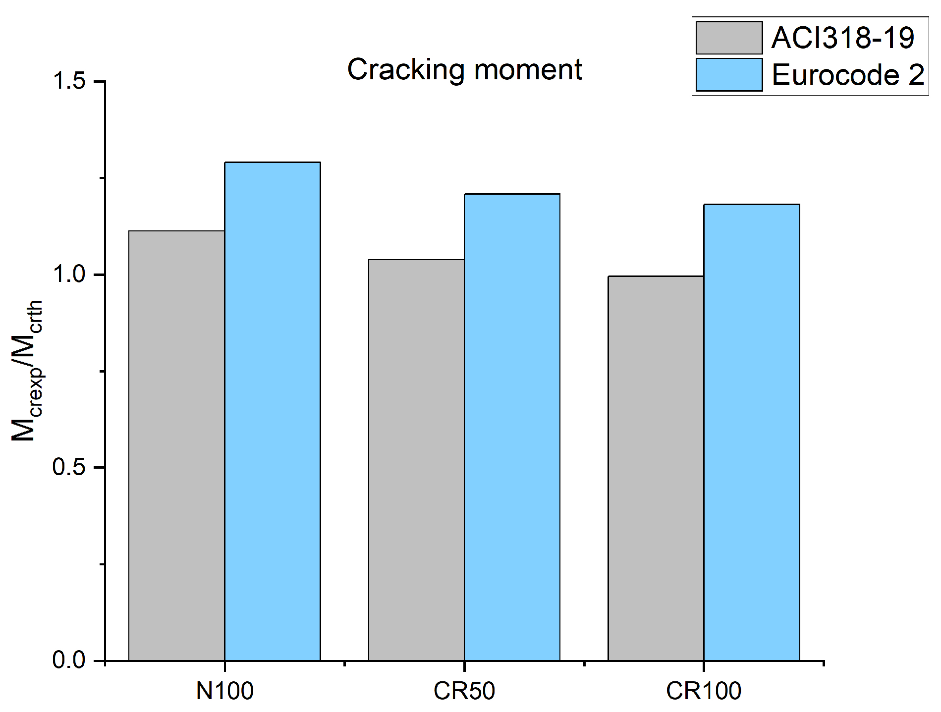
Figure 7 illustrate the relationship between the experimental and theoretical critical moments for all tested beams. A ratio above 1 represents a conservative estimation, while a ratio below 1 indicates a value greater than the experimentally predicted.
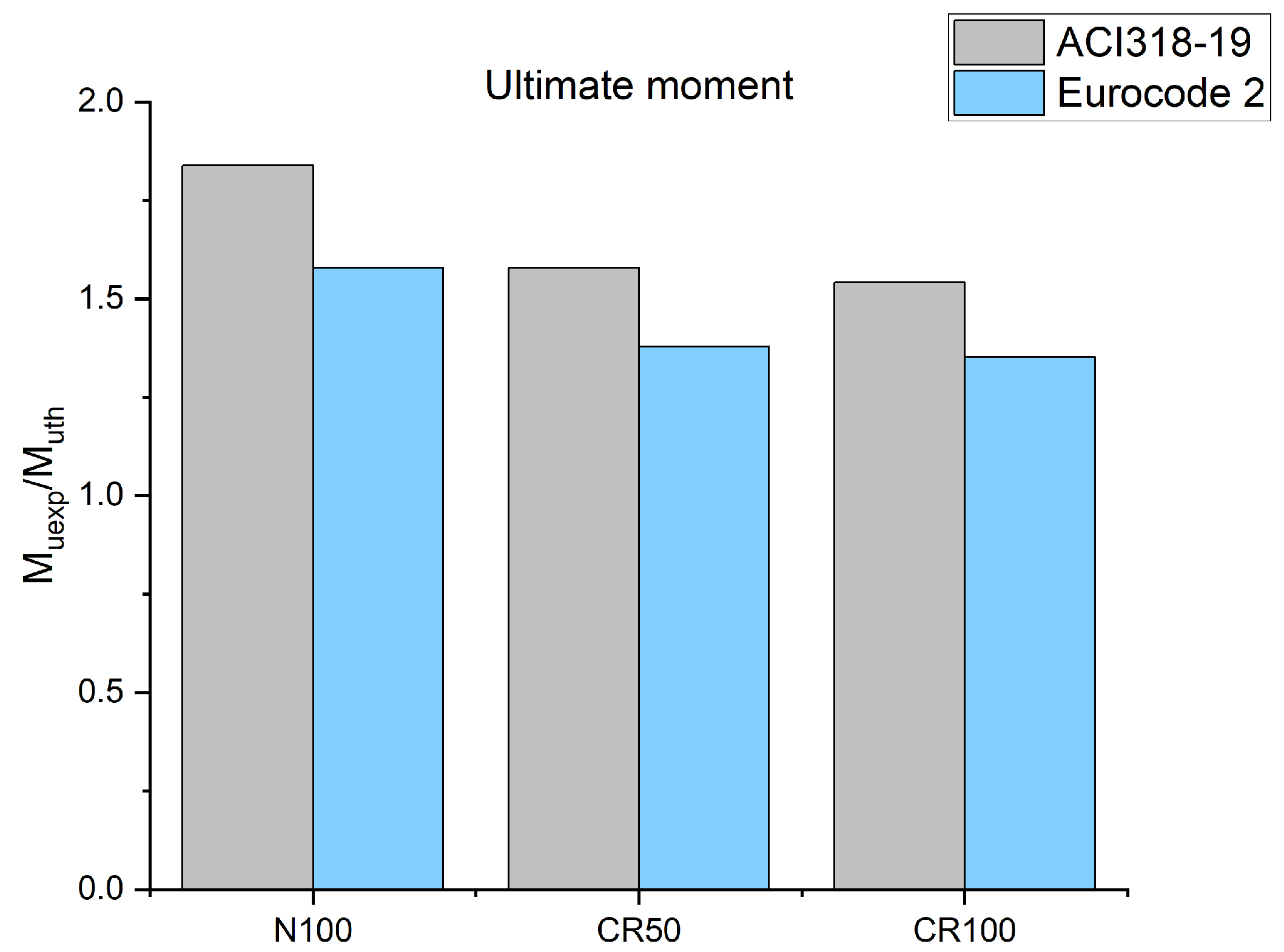
The M c r e x p / M c r t h ratios obtained for N100, CR50, and CR100 were 1.11, 1.04, and 0.99, respectively, according to the ACI 318 code, while the Eurocode 2 ratios were 1.29, 1.21, and 1.18, respectively. The M u e x p / M u t h ratios obtained for N100, CR50, and CR100 were 1.84, 1.58, and 1.54, respectively, according to the ACI 318 code, while the Eurocode 2 ratios were 1.58, 1.38, and 1.35, respectively.
For the critical moment, the prediction of the ACI 318 code was closer to the experimental results. In the case of high replacement percentages (100%), the experimental values were slightly below the theoretical values (0.99). Eurocode 2 yielded a more conservative prediction (1.18). The ACI 318 was more conservative than Eurocode 2 for the end moment prediction.
Figure 8 and 
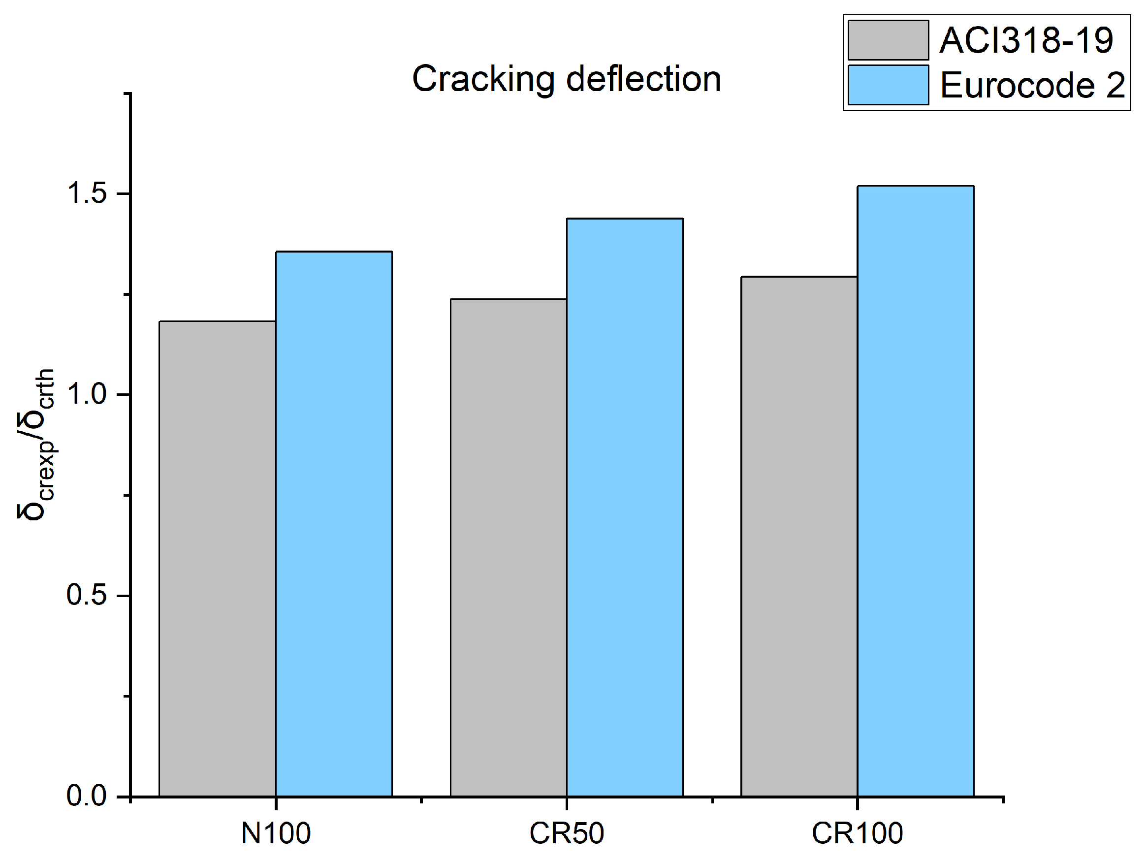
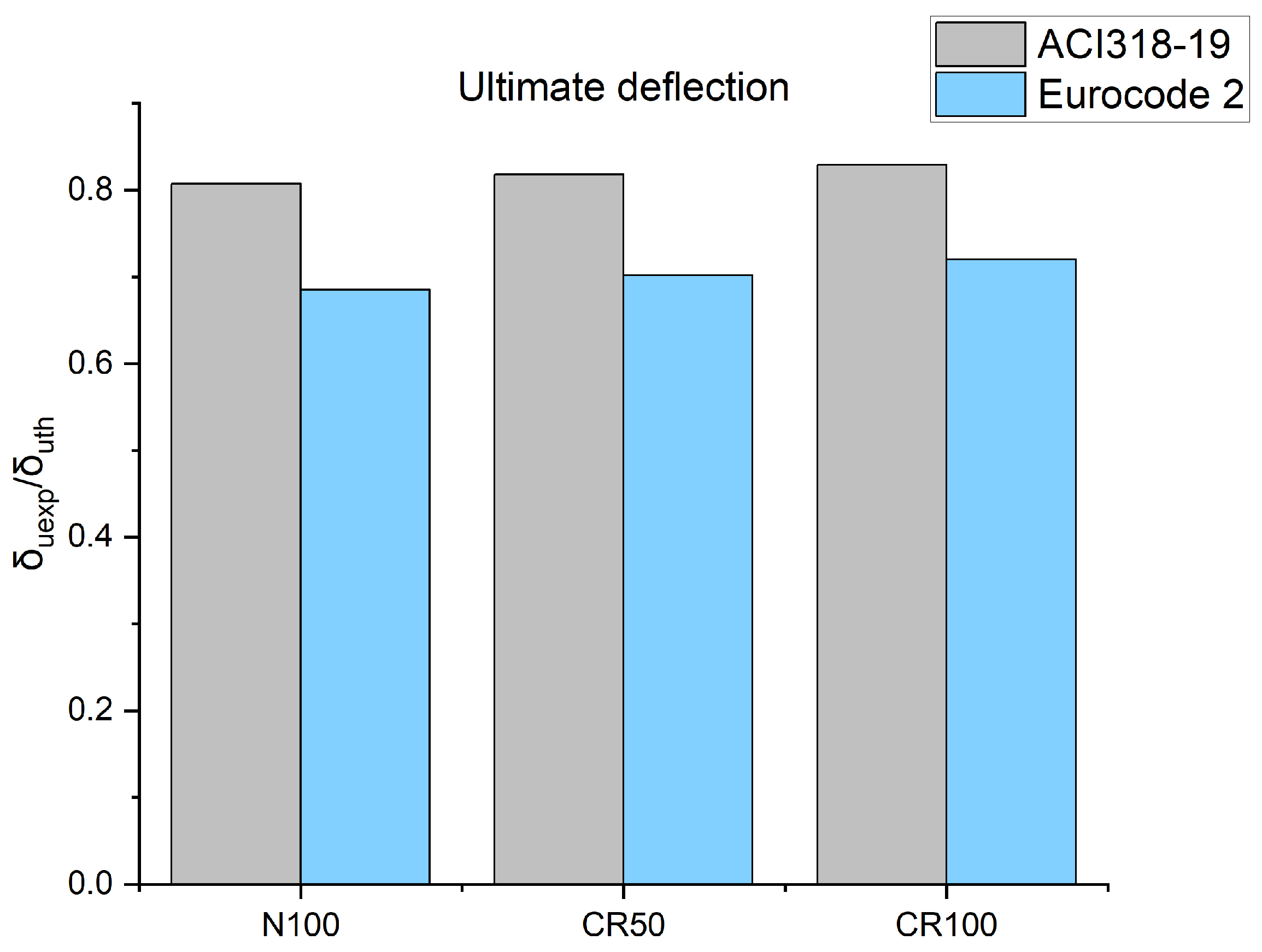
Figure 9 shows the relation between the experimental and theoretical critical and end strains of the studied beams. It can be observed that Eurocode 2 was more conservative in calculating the critical strain; at the same time, both codes overestimated the calculation of the end strains of all series [46].
The δ c r e x p / δ c r t h ratio obtained for the N100, CR50, and CR100 beams was 1.18, 1.24, and 1.29, respectively, according to the ACI 318 code. However, according to Eurocode 2, they were 1.36, 1.44, and 1.52, which shows that the critical strain increases with increasing use of recycled aggregates, mainly due to the lower modulus of elasticity of these series.
The δ u e x p / δ u t h ratio obtained for N100, CR50, and CR100 was 0.81, 0.82, and 0.83, respectively, when using the ACI 318 code, while they were 0.69, 0.70, and 0.72 when using the Eurocode 2.

4. Conclusions

In this study, we conducted experimental and theoretical research on the flexural behavior of concrete beams with RA. Three concrete beams reinforced with different percentages of coated recycled aggregate (0%, 50%, and 100%) were tested. The structural characteristics predicted by the ACI 318-19 and Eurocode 2 codes were assessed. Based on the results, the following conclusions can be drawn:
  • When using the RA, the compressive strength decreased by 3.00% with 50% replacement and 12.73% with 100% replacement, whilehe flexural strength decreased by 8.44% with 50% replacement and 16.62% with 100% replacement. Although the treatment showed slight improvements in the physical properties, inferior results were obtained in terms of the mechanical properties, which could be linked to the different w/c ratios used to ensure the workability of the mixtures and comply with the requirements of industry.
  • The use of enhanced RA revealed a similar cracking pattern in terms of the number and spacing of cracks, indicating that the beams failed in a similar manner.
  • Increasing the percentage of RA reduced the load capacity; in addition, it reduced the end moment by 14.67% and the failure moment by 7.98% for the 50% replacement. For the 100% replacement, the end moment was reduced by 18.39% and the failure moment by 15.48%. For the 50% replacement, the end deflection in the central third was increased by 2.56% and the critical deflection was decreased by 25.71%. Conversely, when 100% replacement was used, the end and critical deflection both increased, by 1.92% and 4.76%, respectively.
  • The theoretical results provided by the equations in the Eurocode 2 and ACI 318-19 codes were compared with the experimental results. The most conservative critical moment standard was Eurocode 2; however, all the experimental critical moments were higher than the theoretical ones, with the exception of the critical moment calculated using ACI 318-19 for the 100% replacement, which resulted in a ratio of approximately 1.
  • The beams with RA had higher critical and end load capacities than the results predicted by the Eurocode 2 and ACI 318-19 codes, indicating that the moment capacity can be estimated using these design.
It should be noted that our study was limited to the situation described above, i.e., the use of low-quality recycled aggregates. It is recommended that further studies be carried out in order to validate the results obtained in the present study.

Author Contributions

Conceptualization, V.L.; methodology, V.L.; formal analysis, C.M.; investigation, V.L. and B.W.; resources, V.L.; data curation, V.L. and B.W.; writing—original draft preparation, C.M.; writing—review and editing, V.L. and B.W.; supervision, V.L.; project administration, V.L.; funding acquisition, V.L. All authors have read and agreed to the published version of the manuscript.

Funding

This research was funded by the National Agency for Research and Development (ANID) under grant number FONDECYT REGULAR 1211135.

Institutional Review Board Statement

Not applicable.

Informed Consent Statement

Not applicable.

Data Availability Statement

The original contributions presented in the study are included in the article; further inquiries can be directed to the corresponding author.

Acknowledgments

The authors gratefully acknowledge the partial support from the Universidad de La Frontera (Chile) and Ministerio de Educación (MINEDUC) (Project FRO2395).

Conflicts of Interest

The authors declare no conflicts of interest.

Appendix A

Table A1. Calculation memory for theoretical ultimate moment (ACI 318-19).
Beam f c (MPa) E s (MPa)b (mm)c (mm)d (mm) d (mm) A s (mm2) M u (kN · m)
N10030.00210,00015051.5225937100.5338.77
CR5029.10210,00015052.2825937100.5338.54
CR10026.18210,00015055.7125937100.5337.72
Table A2. Calculation memory for theoretical ultimate moment (Eurocode 2).
Beam f c (MPa) E s (MPa)b (mm)c (mm)d (mm) d (mm) A s (mm2) M u (kN · m)
N10030.00210,00015047.9725937100.5344.48
CR5029.10210,00015048.7325937100.5344.14
CR10026.18210,00015052.1025937100.5343.06
Table A3. Calculation memory for theoretical critical moment (ACI 318-19).
Beam f c (MPa)nh (mm)b (mm)d (mm) d (mm) A s (mm2) A s (mm2) f r (MPa)I (mm4) M cr (kN · m)
N100308.1630015025937100.53402.123.396379,772,7508.88
CR5029.18.2830015025937100.53402.123.345380,493,8178.77
CR10026.188.7330015025937100.53402.123.172383,079,2838.39
Table A4. Calculation memory for theoretical critical moment (Eurocode 2).
Beam f c (MPa)nh (mm)b (mm)d (mm) d (mm) A s (mm2) A s (mm2) f ctm (MPa) I u (mm4) M cr (kN · m)
N100308.1630015025937100.53402.122.929379,772,7507.66
CR5029.18.2830015025937100.53402.122.870380,493,8177.52
CR10026.188.7330015025937100.53402.122.674383,079,2837.07
Table A5. Calculation memory for theoretical ultimate load (ACI 318-19).
Beam M u (kN · m)l (m) P u (kN)
N10038.776129.22
CR5038.546128.47
CR10037.726125.74
Table A6. Calculation memory for theoretical ultimate load (Eurocode 2).
Beam M u (kN · m)l (m) P u (kN)
N10044.486148.26
CR5044.146147.13
CR10043.066143.52
Table A7. Calculation memory for theoretical critical load (ACI 318-19).
Beam M cr (kN · m)l (m) P cr (kN)
N1008.88629.60
CR508.77629.23
CR1008.39627.96
Table A8. Calculation memory for theoretical critical load (Eurocode 2).
Beam M cr (kN · m)l (m) P cr (kN)
N1007.66625.54
CR507.52625.08
CR1007.07623.57
Table A9. Calculation memory for theoretical ultimate deflection (ACI 318-19).
Beam I eff (mm4)a (mm) P u (kN) E c (MPa)L (mm) δ u (mm)
N100134,152,839600129.2225742.918003.873
CR50135,637,709600128.4725353.918003.867
CR100140,939,136600125.7424048.218003.840
Table A10. Calculation memory for theoretical ultimate deflection (Eurocode 2).
Beam I eff (mm4)a (mm) P u (kN) E c (MPa)L (mm) δ u (mm)
N100132,730,078600148.2625,742.918004.49
CR50134,244,888600147.1325,353.918004.47
CR100139,633,622600143.5224,048.218004.42
Table A11. Calculation memory for theoretical critical deflection (ACI 318-19).
Beam I eff (mm4)a (mm) P cr (kN) E c (MPa)L (mm) δ cr (mm)
N100134,152,83960029.6025,742.918000.887
CR50135,637,70960029.2325,353.918000.880
CR100140,939,13660027.9624,048.218000.854
Table A12. Calculation memory for theoretical critical deflection (Eurocode 2).
Beam I eff (mm4)a (mm) P cr (kN) E c (MPa)L (mm) δ cr (mm)
N100132,730,07860025.5425,742.918000.77
CR50134,244,88860025.0825,353.918000.76
CR100139,633,62260023.5724,048.218000.73

References

  1. Madroñero-Palacios, S.; Guzmán-Hernández, T. Desarrollo sostenible. Aplicabilidad y sus tendencias. Rev. Tecnol. Marcha 2018, 31, 122–130. [Google Scholar] [CrossRef]
  2. Anselmi, L.Á.M.; García, M.Á.O.; Polo, K.A.R. Resistance of concrete with aggregate of clay block crushed as replacement of aggregate thick. Ingeniare 2019, 27, 635–642. [Google Scholar] [CrossRef]
  3. Fernández, L.; Gutiérrez, M. Bienestar Social, Económico y Ambiental para las Presentes y Futuras Generaciones. Inf. Tecnol. 2013, 24, 121–130. [Google Scholar] [CrossRef]
  4. Oikonomou, N. Recycled concrete aggregates. Cem. Concr. Compos. 2005, 27, 315–318. [Google Scholar] [CrossRef]
  5. Piersanti, M.; Shehata, M.H. A study into the alkali-silica reactivity of recycled concrete aggregates and the role of the extent of damage in the source structures: Evaluation, accelerated testing, and preventive measures. Cem. Concr. Compos. 2022, 129, 104512. [Google Scholar] [CrossRef]
  6. Duan, H.; Miller, T.R.; Liu, G.; Tam, V.W. Construction debris becomes growing concerns of growing cities. Waste Manag. 2019, 83, 1–5. [Google Scholar] [CrossRef]
  7. Wang, C.; Xiao, J.; Zhang, C.; Xiao, X. Structural health monitoring and performance analysis of a 12-story recycled aggregate concrete structure. Eng. Struct. 2020, 205, 110102. [Google Scholar] [CrossRef]
  8. Liu, J.; Yi, Y.; Wang, X. Exploring factors influencing construction waste reduction: A structural equation modeling approach. J. Clean. Prod. 2020, 276, 123185. [Google Scholar] [CrossRef]
  9. Kong, L.; Ma, B. Evaluation of environmental impact of construction waste disposal based on fuzzy set analysis. Environ. Technol. Innov. 2020, 19, 100877. [Google Scholar] [CrossRef]
  10. Zhang, B.; Feng, Y.; Xie, J.; Chen, W.; Xue, Z.; Zhao, G.; Li, Y.; Li, J.; Yang, J. Compressive behaviour and microstructures of concrete incorporating pretreated recycled powder/aggregates: The coupling effects of calcination and carbonization. J. Build. Eng. 2023, 68, 106158. [Google Scholar] [CrossRef]
  11. Anike, E.E.; Saidani, M.; Olubanwo, A.O.; Anya, U.C. Flexural performance of reinforced concrete beams with recycled aggregates and steel fibres. Structures 2022, 39, 1264–1278. [Google Scholar] [CrossRef]
  12. Diotti, A.; Cominoli, L.; Plizzari, G.; Sorlini, S. Experimental Evaluation of Recycled Aggregates, Washing Water and Cement Sludge Recovered from Returned Concrete. Appl. Sci. 2021, 12, 36. [Google Scholar] [CrossRef]
  13. Wang, B.; Yan, L.; Fu, Q.; Kasal, B. A Comprehensive Review on Recycled Aggregate and Recycled Aggregate Concrete. Resour. Conserv. Recycl. 2021, 171, 105565. [Google Scholar] [CrossRef]
  14. Zhang, J.; Zhu, X.; Zhou, M.; Huang, X. Experimental Study on Preparation and Characteristics of Concrete Modified by Construction Waste. Appl. Sci. 2024, 14, 1974. [Google Scholar] [CrossRef]
  15. Zeyad, A.M. Sustainable concrete Production: Incorporating recycled wastewater as a green building material. Constr. Build. Mater. 2023, 407, 133522. [Google Scholar] [CrossRef]
  16. Wang, J.; Che, Z.; Zhang, K.; Fan, Y.; Niu, D.; Guan, X. Performance of recycled aggregate concrete with supplementary cementitious materials (fly ash, GBFS, silica fume, and metakaolin): Mechanical properties, pore structure, and water absorption. Constr. Build. Mater. 2023, 368, 130455. [Google Scholar] [CrossRef]
  17. Siletani, A.H.; Asayesh, S.; Shirzadi Javid, A.A.; Habibnejad Korayem, A.; Ghanbari, M.A. Influence of coating recycled aggregate surface with different pozzolanic slurries on mechanical performance, durability, and micro-structure properties of recycled aggregate concrete. J. Build. Eng. 2024, 83, 108457. [Google Scholar] [CrossRef]
  18. Gunasekara, C.; Seneviratne, C.; Law, D.W.; Setunge, S. Feasibility of Developing Sustainable Concrete Using Environmentally Friendly Coarse Aggregate. Appl. Sci. 2020, 10, 5207. [Google Scholar] [CrossRef]
  19. Basit, A.; Hameed, R.; Abbas, S.; Karam, M.S.; Shahzad, S.; Kazmi, S.M.S.; Munir, M.J. Impact of Recycled Concrete and Brick Aggregates on the Flexural and Bond Performance of Reinforced Concrete. Appl. Sci. 2024, 14, 2719. [Google Scholar] [CrossRef]
  20. Muhammad, F.; Harun, M.; Ahmed, A.; Kabir, N.; Khalid, H.R.; Hanif, A. Influence of bonded mortar on recycled aggregate concrete properties: A review. Constr. Build. Mater. 2024, 432, 136564. [Google Scholar] [CrossRef]
  21. Soares, D.; De Brito, J.; Ferreira, J.; Pacheco, J. In situ materials characterization of full-scale recycled aggregates concrete structures. Constr. Build. Mater. 2014, 71, 237–245. [Google Scholar] [CrossRef]
  22. Ferrández, D.; Zaragoza-Benzal, A.; Pastor Lamberto, R.; Santos, P.; Michalak, J. Optimizing Masonry Mortar: Experimental Insights into Physico-Mechanical Properties Using Recycled Aggregates and Natural Fibers. Appl. Sci. 2024, 14, 6226. [Google Scholar] [CrossRef]
  23. Wang, S.; Hu, J.; Sun, Z.; Gao, Y.; Yan, X.; Xue, X. Efficiency and Mechanism of Surface Reinforcement for Recycled Coarse Aggregates via Magnesium Phosphate Cement. Materials 2024, 17, 122. [Google Scholar] [CrossRef] [PubMed]
  24. Tan, H.; Yang, Z.; Deng, X.; Guo, H.; Zhang, J.; Zheng, Z.; Li, M.; Chen, P.; He, X.; Yang, J.; et al. Surface reinforcement of recycled aggregates by multi-diameter recycled powder blended cement paste. J. Build. Eng. 2023, 64, 105609. [Google Scholar] [CrossRef]
  25. Martirena, F.; Castaño, T.; Alujas, A.; Orozco-Morales, R.; Martinez, L.; Linsel, S. Improving quality of coarse recycled aggregates through cement coating. J. Sustain.-Cem.-Based Mater. 2017, 6, 69–84. [Google Scholar] [CrossRef]
  26. Pacheco, J.; de Brito, J.; Ferreira, J.; Soares, D. Flexural load tests of full-scale recycled aggregates concrete structures. Constr. Build. Mater. 2015, 101, 65–71. [Google Scholar] [CrossRef]
  27. Abushanab, A.; Alnahhal, W.; Sohail, M.G.; Alnuaimi, N.; Kahraman, R.; Altayeh, N. Mechanical and durability properties of ultra-high performance steel FRC made with discarded materials. J. Build. Eng. 2021, 44, 103264. [Google Scholar] [CrossRef]
  28. Kisku, N.; Rajhans, P.; Panda, S.; Pandey, V.; Nayak, S. Microstructural investigation of recycled aggregate concrete produced by adopting equal mortar volume method along with two stage mixing approach. Structures 2020, 24, 742–753. [Google Scholar] [CrossRef]
  29. Fonseca, N.; de Brito, J.; Evangelista, L. The influence of curing conditions on the mechanical performance of concrete made with recycled concrete waste. Cem. Concr. Compos. 2011, 33, 637–643. [Google Scholar] [CrossRef]
  30. ASTM C595/C595M-21; Standard Specification for Blended Hydraulic Cements. ASTM International: West Conshohocken, PA, USA, 2021.
  31. Lu, C.; Yu, Q.; Wei, J.; Niu, Y.; Zhang, Y.; Lin, C.; Chen, P.; Shi, C.; Yang, P. Influence of interface transition zones (ITZ) and pore structure on the compressive strength of recycled aggregate concrete. Constr. Build. Mater. 2024, 456, 139299. [Google Scholar] [CrossRef]
  32. Ghorbel, E.; Wardeh, G. Influence of recycled coarse aggregates incorporation on the fracture properties of concrete. Constr. Build. Mater. 2017, 154, 51–60. [Google Scholar] [CrossRef]
  33. NCh204-2006; Acero—Barras laminadas en caliente para hormigón armado. INN: Santiago, Chile, 2006.
  34. Wenzel, B.; Bustamante, M.; Muñoz, P.; Ortega, J.M.; Loyola, E.; Letelier, V. Physical and mechanical behavior of concrete specimens using recycled aggregate coated using recycled cement paste. Constr. Build. Mater. 2023, 393, 132015. [Google Scholar] [CrossRef]
  35. Fathalla, E.; Mihaylov, B. Shear behaviour of deep beams strengthened with high-strength fiber reinforced concrete jackets. Eng. Struct. 2025, 325, 119404. [Google Scholar] [CrossRef]
  36. ASTM C39/C39M-21; Standard Test Method for Compressive Strength of Cylindrical Concrete Specimens. ASTM International: West Conshohocken, PA, USA, 2021.
  37. ASTM C469/C469M-14; Standard Test Method for Static Modulus of Elasticity and Poisson’s Ratio Concrete in Compression. ASTM International: West Conshohocken, PA, USA, 2014.
  38. ASTM C78/C78M-18; Standard Test Method for Flexural Strength of Concrete (Using Simple Beam with Third-Point Loading). ASTM International: West Conshohocken, PA, USA, 2018.
  39. Yuan, H.; Chen, Y.; Kang, L.; Geng, T.; Ma, K. Compressive axial load performance of GFRP–confined recycled aggregate concrete–filled steel tube stub columns. J. Constr. Steel Res. 2024, 220, 108835. [Google Scholar] [CrossRef]
  40. Kwan, W.H.; Ramli, M.; Kam, K.J.; Sulieman, M.Z. Influence of the amount of recycled coarse aggregate in concrete design and durability properties. Constr. Build. Mater. 2012, 26, 565–573. [Google Scholar] [CrossRef]
  41. Li, S.; Sun, Y.; Qian, Y.; Chen, W.; Hu, J. Flexural behaviour of post-tensioned precast beams manufactured with basalt-fibre-reinforced recycled concrete–conventional concrete. J. Build. Eng. 2024, 89, 109154. [Google Scholar] [CrossRef]
  42. Arezoumandi, M.; Smith, A.; Volz, J.S.; Khayat, K.H. An experimental study on flexural strength of reinforced concrete beams with 100% recycled concrete aggregate. Eng. Struct. 2015, 88, 154–162. [Google Scholar] [CrossRef]
  43. Abushanab, A.; Alnahhal, W. Flexural behavior of reinforced concrete beams prepared with treated Wastewater, recycled concrete Aggregates, and fly ash. Structures 2022, 45, 2067–2079. [Google Scholar] [CrossRef]
  44. CEN. Eurocode 2: Design of Concrete Structures—Part 1-1: General Rules and Rules for Buildings; European Committee for Standardization (CEN): Brussels, Belgium, 2004. [Google Scholar]
  45. ACI Committee 318. Building Code Requirements for Structural Concrete (ACI 318-19) and Commentary; American Concrete Institute: Indianapolis, IN, USA, 2019. [Google Scholar]
  46. Das, P.; Chakraborty, S.; Barai, S.V. Flexural behaviour of fly ash incorporated ferrochrome slag aggregate reinforced concrete beam. J. Build. Eng. 2023, 76, 107317. [Google Scholar] [CrossRef]
Figure 1. Particle size distribution of the aggregates (i.e., NA and RA).
Applsci 15 00829 g001
Figure 2. Recycled aggregate without treatment (right) and coated recycled aggregate (left).
Applsci 15 00829 g002
Figure 3. (a) Details of the reinforced beams and (b) loading frame.
Applsci 15 00829 g003
Figure 4. Cracking patterns and failure modes of the tested beams.
Applsci 15 00829 g004
Figure 5. Load–deflection curves for the tested beams.
Applsci 15 00829 g005
Figure 6. Relationship between the experimental and theoretical cracking moments ( M c r ).
Applsci 15 00829 g006
Figure 7. Relationship between the experimental and theoretical ultimate moments ( M u ).
Applsci 15 00829 g007
Figure 8. Relationship between experimental and theoretical cracking deflection values ( δ c r ).
Applsci 15 00829 g008
Figure 9. Relationship between experimental and theoretical ultimate deflection values ( δ u ).
Applsci 15 00829 g009
Table 1. Physical properties of the aggregates.
Aggregate TypeSpecific Gravity ( g / cm 3 )Water Absorption (%)LA Abrasion Loss (%)
CNA12.651.4119.93
FNA22.482.17-
CRA32.277.1937.94
C-CRA42.266.8140.20
1 Coarse Natural Aggregate, 2 Fine Natural Aggregate, 3 Coarse Recycled Aggregate, 4 Coated Coarse Recycled Aggregate.
Table 2. Mix proportions of concrete ( kg / m 3 ).
SampleWaterCementw/c RatioCoarse NACoarse RCAFine NASP
N1001843820.48106107727.65
CR502243820.595315317727.65
CR1002383820.62010617727.65
Table 3. Mechanical properties of series.
SampleCompressive Strength (MPa)Standard DeviationModulus of Elasticity (MPa)Standard DeviationFlexural Strength (MPa)Standard Deviation
N10030.002.99%332760.51%3.795.57%
CR5029.101.84%319972.26%3.474.64%
CR10026.185.01%307175.26%3.164.49%
Table 4. Summary of results for the tested beams.
BeamInitial CrackingYieldingUltimate StrengthFailure
Load (kN)Deformation (mm)Load (kN)Deformation (mm)Load (kN)Deformation (mm)Load (kN)Deformation (mm)
N10063.401.86174.008.41205.4037.44168.0038.05
CR5069.412.34165.308.92198.6138.27163.3638.49
CR10065.222.30169.658.51194.3445.16179.1245.79
Table 5. List of code-based expressions used to predict the cracking moments of the beams.
Design CodeCracking Moment (N · mm)
ACI 318–19 M c r = f r · I g y t = modulus of rupture of concrete (Mpa)
Where:
f r = 0.62 · f c = a modification factor
f c = concrete compressive strength, (MPa)
I g = gross moment of inertia, mm 4
Y t = distance from the axis passing through the centroid of the cross section to the face in traction, (mm)
Eurocode 2 M c r = f c t m · I u ( h X u ) = mean concrete tensile strength, (MPa)
Where:
I u = moment inertia of uncracked section transformed to concrete, ( m m 4 )
h = height of the cross-section (mm)
X u = neutral axis depth of uncracked section, (mm)
f c t m 1 = mean value of axial tensile strength of concrete
E c o n c r e t e e f f e c t i v e = effective modulus of elasticity of concrete (MPa)
f c t m = 0.3 · f c 0.67
X u = h b 2 2 + ( α e 1 ) ( A s · d + A s 2 · d 2 ) b h + ( α e 1 ) ( A s + A s 2 )
I u = b h 3 12 + b h · ( h 2 X u ) 2 + ( α e 1 ) · [ A s · ( d X u ) 2 + A s 2 ( X u d 2 ) 2 ]
α e = E s t e e l E c o n c r e t e e f f e c t i v e
A s = tensile steel reinforcement
A s 2 = compression steel reinforcement
d = distance from extreme compression to tensile reinforcement
d 2 = distance from extreme compression to compression reinforcement
1 f c t m : Because no direct tensile tests were performed, the value from the standard Eurocode 2 Table 3.1 is used here.
Table 6. List of expressions used to predict the ultimate moment, capacity, and deflection of the beams.
Expressions Used
Ultimate moment (N · mm) M u = α · f c · a · b · ( d a 2 ) + A s · f s · ( d d )
Where:
d = distance from the compression end to the centroid of the tensile reinforcement (mm)
d = distance from the compression end to the centroid of the compression reinforcement (mm)
A s = compression steel reinforcement ( mm 2 )
A s = tensile steel reinforcement ( mm 2 )
f c = compressive strength in a cylindrical specimen at 28 days (MPa)
f s = yield strength of steel (MPa)
a = depth of the compressive block (mm)
a = ( A s A s ) · f y α f c · b
α = 0.85 [ACI 318-19]
α = 1 , where f c 50 1 f c 50 200 , where 50 f c 70 [Eurocode 2]
Load capacity ( k N ) P = 2 · ( M l )
Where:
l = load to support distance (mm)
M = critical or ultimate moment, if critical or ultimate load is desired, respectively (N · mm)
Deflection ( m m ) δ = P a 48 · E I e f f · ( 3 L 2 4 a 2 ) = deflection (mm)
Where:
a = shear span (mm)
I e f f = effective moment of inertia ( mm 4 )
L = effective length (mm)
E = modulus of elasticity of concrete (MPa)
Table 7. Test results of the studied beams compared to ACI 318-19 and Eurocode 2.
N100CR50CR100
P u (kN) 1Experimental237.66202.80193.95
ACI 318-19129.22128.47125.74
Eurocode 2148.26147.13143.52
P c r (kN) 2Experimental32.9530.3227.85
ACI 318-1929.6029.2327.96
Eurocode 225.5425.0823.57
M u (kN) 3Experimental71.3060.8458.19
ACI 318-1938.7738.5437.72
Eurocode 244.4844.1443.06
M c r (kN) 4Experimental9.899.108.36
ACI 318-198.888.778.39
Eurocode 27.667.527.07
δ u (kN) 5Experimental3.123.203.18
ACI 318-193.873.863.84
Eurocode 24.494.474.42
δ c r (kN) 6Experimental1.051.081.10
ACI 318-190.890.880.85
Eurocode 20.770.760.73
1 P u : Ultimate Load, 2 P c r : Cracking Load, 3 M u : Ultimate Moment, 4 M c r : Cracking Moment, 5 δ u : Ultimate Deflection, 6 δ c r : Cracking Deflection.
Disclaimer/Publisher’s Note: The statements, opinions and data contained in all publications are solely those of the individual author(s) and contributor(s) and not of MDPI and/or the editor(s). MDPI and/or the editor(s) disclaim responsibility for any injury to people or property resulting from any ideas, methods, instructions or products referred to in the content.

