Abstract
A detailed theoretical design of an electric resonance-based coupler for dynamic wireless power transfer (DWPT) at the mobile robot level is presented. The scattering matrix of the coupler was derived by transforming and multiplying transmission matrices for each circuit network in a practical equivalent circuit that accounted for loss resistance. This theoretical approach was validated through equivalent circuit models, yielding results consistent with 3D full-wave simulations and showing an error rate of less than 1%. Additionally, a null-power point characteristic, where efficiency sharply decreases when the receiver moves outside the transmitter’s range, was observed. The detailed theoretical design of the practical equivalent circuit for electric resonance-based dynamic WPT couplers is expected to contribute to the design of couplers for various specifications in future applications.
1. Introduction
Wireless power transfer (WPT) technology is considered essential for ensuring a continuous power supply to all IoT devices. From smartphones, wearable devices, and home appliances to mobility units, such as automobiles, IoT devices are increasingly integrating more functions, placing them at the forefront of modern technological innovation. WPT, which eliminates the need for physical connections, offers significant experiential advantages to users. Furthermore, it operates across various environments, including smart homes, smart cities, industrial automation, and autonomous vehicles. In these settings, WPT overcomes limitations related to charging time and location, making it a critical enabler for the intelligent operation of devices through an uninterrupted power supply [1,2,3,4,5].
Particularly, DWPT technology for dynamic wireless charging enables continuous charging even during movement, addressing challenges related to battery capacity and charging infrastructure. As such, it has been actively studied for electric vehicle (EV) applications [6,7,8]. However, DWPT technology is not limited to EVs. It is a necessary technology that should be developed to provide a continuous power supply across all power-consuming devices, including industrial robots, equipment, smart appliances, and IoT devices.
Since the power requirements vary across applications, appropriately sized WPT couplers must be designed. For instance, EV wireless charging, which typically demands outputs ranging from several kW to tens of kW, requires WPT coupler coils with widths exceeding 0.2 m [9,10,11]. In contrast, couplers for mobile robots, which operate at an output level of approximately 24–50 W, should be practically smaller than 0.2 m [12,13]. Furthermore, a coreless track-based wireless charging system capable of transmitting and receiving over 100 W has been studied to support the free movement of robots [14].
These technologies are based on inductive wireless power transfer (IPT) using magnetic induction and magnetic resonance. Initially proposed by an MIT research team in 2007, IPT has since been extensively studied [15]. This approach, like the aforementioned studies, achieves high efficiency at close transmitter–receiver distances. However, the strong electromagnetic fields generated by IPT systems cannot be overlooked due to their potential impacts on other electronic devices and human health [16,17]. Additionally, the induced voltage caused by magnetic fields can lead to malfunctions in other devices [18,19,20,21]. Given these potential risks, international guidelines regulating electromagnetic exposure limits have been updated [22]. Based on these standards, studies have also been conducted to analyze the electromagnetic fields induced within the human body [23].
In contrast, capacitive wireless power transfer (CPT) using electric resonance is free from these issues [24]. Notably, designing a DWPT system based on IPT requires complex structures [25,26], whereas CPT allows for relatively simpler and more efficient system designs [27,28].
The structure of a four-plate CPT coupler is categorized into parallel and stacked configurations [29]. Generally, the parallel structure features two transmitting metal plates and two receiving metal plates arranged to face each other [30]. In the stacked structure, the two transmitting plates are stacked vertically, and the receiving plates are arranged in the same manner, with the two plates on each side layered on top of each other [31]. These two configurations can be designed and applied according to specific objectives [32,33].
Dynamic wireless capacitive power transfer (DCPT) systems also apply these structures [34,35,36]. As illustrated in Figure 1, mutual coupling is formed between the transmitter plate and receiving plate, both composed of metal, facilitating power transfer through electric field coupling.
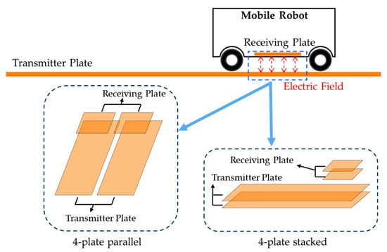
Figure 1.
Dynamic wireless-charging systems for mobile robots.
Despite extensive research on WPT applications, the equivalent circuit analysis required to understand the electromagnetic characteristics of couplers remains insufficient. From a safety perspective, WPT systems can experience unnecessary power losses due to structural properties or interference from external objects. To address this, technologies using additional sensors for external object detection have been studied [37,38,39].
However, these techniques are primarily applied to IPT systems. For CPT systems, a method for detecting external objects or receiver position changes by evaluating the symmetry of the capacitance matrix has been proposed [40]. Ultimately, an equivalent circuit analysis is essential for examining coupling variations caused by changes in the electromagnetic characteristics of couplers. In addition, studies have demonstrated stable power transfer in experiments involving biological entities and uniform performance in multi-transmitter and receiver systems [41,42].
This study provides a theoretical design of a practical equivalent circuit model for a basic DCPT coupler, accounting for loss resistance. The results offer validated findings that can support the design of couplers for various applications. The contributions of this study can be summarized as follows:
- This study presents high-accuracy validation results through a theoretical design based on the practical equivalent circuit (PEC) model of a four-plate parallel DCPT coupler, compared with electromagnetic simulation results.
- It provides an analysis of the correlation between S21 and mutual capacitance in the four-plate parallel DCPT coupler.
This study aimed to theoretically design a four-plate parallel DCPT coupler using an equivalent circuit approach. For this purpose, the basic equivalent circuit of a CPT coupler was transformed into a practical equivalent circuit that accounted for coupler losses. Each parameter of the equivalent circuit was defined based on the calculation of self-capacitance and mutual capacitance from a model designed using the 3D full-wave simulation software. The transmission matrix was used to calculate the power transfer efficiency of the equivalent circuit, including the impedance-matching network. The theoretical calculations were validated through equivalent circuit calculations and compared with 3D electromagnetic simulation results. Furthermore, the correlation between the theoretically calculated mutual capacitance and power transfer efficiency was analyzed to provide a detailed understanding of the four-plate parallel DCPT structure.
2. Model of Four-Plate Parallel DCPT Coupler
2.1. Theoretical Design Method of Equivalent Circuit
A four-plate CPT system using electric resonance is typically configured as shown in Figure 2. It consists of four metal plates for wireless power transfer, which are electrically connected to the transmitter and receiver circuits on either side. A DC voltage source is converted into an AC voltage at the transmitter, passing through an impedance-matching circuit. The AC voltage source generates electric field coupling between the metal plates, enabling power transfer. To achieve maximum coupling at the desired operating frequency, the impedance-matching circuits on both the transmitter and receiver sides must be accurately designed. This ensures high wireless power transfer efficiency by minimizing the reflected power at the receiver through the alignment of source and load impedances. Therefore, a vector network analysis of the coupler, including impedance matching, is essential. This study aimed to analyze the four-plate parallel DCPT coupler, incorporating an impedance-matching circuit.
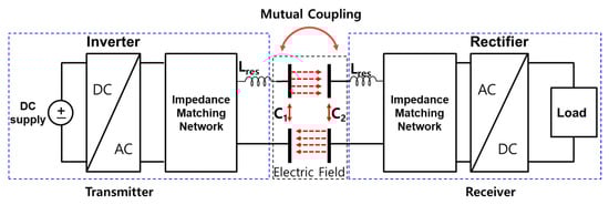
Figure 2.
Topology of CPT system.
The equivalent circuit of the coupler structure, where mutual coupling occurs, is shown in Figure 3, as derived from the structure in Figure 2. In Figure 3a, self-capacitance C1 is formed between the two metal plates on the transmitter side, while self-capacitance C2 is formed between the two metal plates on the receiver side. Since the transmitter and receiver are not electrically connected in the circuit, mutual capacitance CM is established between them. When this equivalent circuit is transformed into a T-model, it is represented as shown in Figure 3b. In this configuration, the metal plates on the transmitter and receiver sides can be expressed as being connected in the circuit, where CM appears in parallel with C1 and C2. Consequently, the combined capacitance can be calculated as a parallel sum and represented in a T-type equivalent circuit, as shown in Figure 3c.
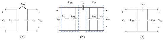
Figure 3.
Equivalent circuits of CPT coupler. (a) Basic equivalent circuit; (b) practical equivalent circuit; (c) simplified practical equivalent circuit.
This study provides a theoretical design of the practical equivalent circuit (PEC) by incorporating a lumped inductor for resonance and an impedance-matching circuit. The S-parameter matrix is derived by multiplying the transmission matrices of each circuit network. Among the parameters of the equivalent circuit, the self-capacitances C1 and C2 and the mutual capacitance CM are obtained using the 3D electromagnetic simulation tool Ansys Q3D. The parameters of the impedance-matching circuit are determined based on the impedance of the coupler designed in the 3D full-wave simulation tool ANSYS HFSS.
The transmission coefficient of the coupler is compared between the theoretical calculations of the equivalent circuit model and the results of 3D full-wave analysis using ANSYS HFSS. According to previous studies, equivalent circuit modeling and simulation validation alone can yield results consistent with experimental measurements [43]. Therefore, this study focuses on providing equivalent circuit analysis through simulation-based validation, excluding experimental measurements.
2.2. Simulation Model of Four-Plate Parallel DCPT
Figure 4 illustrates the four-plate parallel DCPT model analyzed in this study, with the specifications detailed in Table 1. The transmitter comprises plates P1 and P2, while the receiver consists of plates P3 and P4. Considering its design on a PCB substrate, the model uses a 0.035 mm thick copper sheet and a 1.52 mm thick dielectric substrate. In Figure 4a, the width L of both the transmitter and receiver substrates is 90 mm, the length TW of the transmitter substrate is 165 mm, and the length RW of the receiver substrate is 70 mm. The transmitter and receiver are separated by a gap of 10 mm.
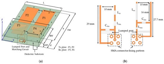
Figure 4.
Configuration of 4-plate parallel DCPT coupler. (a) Overall structure; (b) lumped port and matching circuit.

Table 1.
Specifications of 4-plate parallel DCPT coupler.
Figure 4b depicts the circuit components, including the ports and matching circuits for the transmitter and receiver shown in (a). The transmission line width is 1 mm, and the positions of passive components reflect their actual sizes. On the left is a top view of the transmitter circuit, while on the right is a bottom-up view of the receiver circuit. The hole at the edge of the substrate is a support-fastening part used to secure the coupler during manufacturing. To accommodate practical design considerations, additional soldering pads for securing SMA connectors are included.
The simulation results of this model are used to determine the self-capacitance and mutual capacitance, which are parameters of the equivalent circuit model. The mutual capacitance and transmission characteristics are observed as the receiver moves along the x-axis. Observations are made from −30 mm to 120 mm, covering the range where the receiver fully moves out of the area corresponding to the transmitter’s metal plates. Additionally, to observe the efficiency under misalignment, the transmission characteristics are observed in the range of −50 mm to 50 mm along the y-axis. The component values of the matching circuit, along with the self-capacitance and mutual capacitance calculation results, are described in conjunction with the equivalent circuit model.
2.3. Equivalent Circuit Model of Four-Plate Parallel DCPT
Figure 5 illustrates the equivalent circuit, including the CPT impedance-matching circuit. Figure 5a represents the equivalent circuit that incorporates the parasitic components of the elements and the inherent loss resistance of the coupler. The parasitic capacitances Ctmp, Ctrp, Crmp, and Crrp are negligible. Similarly, the parasitic resistances Rtm, Rtr, and Rrr are extremely small and are, therefore, combined with the loss resistance of the coupler for calculation. Consequently, the equivalent circuit shown in Figure 5b is used for further calculations.
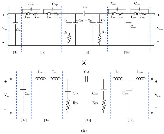
Figure 5.
Practical equivalent circuit model of four-plate parallel DCPT coupler. (a) Equivalent circuit indicating parasitic components; (b) simplified practical equivalent circuit (PEC).
The self-capacitances CTX and CRX and the mutual capacitance CM of the four-plate parallel CPT can be calculated using Equation (1) [44]. Descriptions and values for each parameter in Figure 5b are provided in Table 2. The values of the resonant inductors and matching circuit components are fixed to a single value for use in electromagnetic analysis. The values in Table 2 are the results of matching when the receiver is in its original position, as shown in Figure 4.
Table 2.
Equivalent parameters of 4-plate parallel DCPT.
When the receiver moves along the x-axis or y-axis, changes in the impedance and coupling degree may cause variations in self-capacitance and mutual capacitance. The self-capacitance of the coupler is calculated based on the impedance obtained from electromagnetic analysis. This is determined using formulas related to the resonant frequency and LC circuit characteristics. The capacitance values are derived by substituting the imaginary part of the Z-parameters in the target frequency range, and these values are applied to the equivalent parameters. Since the obtained values include the effects of mutual capacitance, a separate process to exclude mutual capacitance, as described in the calculation using Equation (1), is necessary.
The PEC model considers the loss resistance of the coupler structure. RTX and RRX are determined through an optimization process by comparing the power transfer efficiency of the equivalent circuit model with the electromagnetic simulation. These values are then applied to the circuit analysis for cases where the receiver moves.
Ltr and Lrr are resonant inductors, and significant differences in their values arise due to the disparity in the self-capacitance of the transmitter and receiver couplers. This basic impedance difference also leads to variations in the configuration of the impedance-matching circuit. For the transmitter, a series inductor is connected first, followed by a parallel capacitor, to achieve impedance matching from the perspective of input impedance. This configuration differs from a typical LC-matching network. However, other forms of impedance-matching circuits may also be employed, and this is not a strict limitation.
The S-parameters of the equivalent circuit shown in Figure 5b can be calculated through the transformation of the transmission matrix. The overall S-parameters of the equivalent circuit can be obtained by multiplying the transmission matrices of each circuit network. The transmission matrix for each circuit network in the equivalent circuit is expressed as shown in Equation (2). When expressed in impedance form, it is represented as Equation (3).
According to the formula for converting a transmission matrix into a scattering matrix, the equations can be simplified using the following relationships. By representing the elements of the 2 × 2 transmission matrix as t and applying the substitution in Equation (4) to simplify each element of the converted scattering matrix, it can be expressed as shown in Equation (5). To represent the scattering matrix for each circuit network, as described in Equation (3), the parameters required to express it in the form of Equation (5) are calculated and presented in Table 3. Consequently, as shown in Equation (6), the scattering matrix of the entire equivalent circuit is calculated by multiplying the scattering matrices of each circuit network.
Table 3.
Parameters of the S-matrix of each detailed circuit network.
Table 3.
Parameters of the S-matrix of each detailed circuit network.
| Matrix | Parameter |
|---|---|
3. Results and Discussion
Figure 6 compares the S21 graphs of PEC and HFSS when the Rx movement distance is 0 mm. The comparison is divided into before and after impedance matching. The S21 before impedance matching was close to 0, and the PEC results were the same. After impedance matching, the resonant frequency and the maximum value of S21 for both PEC and electromagnetic simulation were 6.35 MHz and 0.86, respectively, showing identical results. As previously described, the CTX and CRX of the equivalent circuit were accurate values calculated through simulation, and CM was adjusted through the optimization process of the equivalent circuit model. Additionally, the coupler loss resistances RTX and RRX were also tuned to obtain accurate graphs.
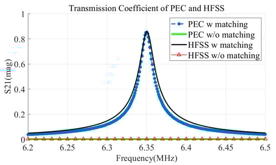
Figure 6.
Comparison of transmission coefficient by impedance matching.
Figure 7 shows the maximum S21 and the magnetic and mutual capacitances as the receiving unit moves along the x-axis from −30 mm to 120 mm. The magnetic and mutual capacitances tended to remain constant when the receiving unit was within the metal plate area of the transmitting unit, between 0 mm and 90 mm. Outside this area, as inferred from Equation (1), a decrease in mutual capacitance corresponded to an increase in magnetic capacitance. Additionally, when compared with the maximum S21, the mutual capacitance showed a similar trend within the metal plate area of the transmitting unit. However, the maximum S21 sharply decreased in the regions beyond the metal plate area of the transmitting unit, between −30 mm to 0 mm and 90 mm to 120 mm.
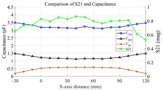
Figure 7.
S21 and capacitance by x-axis distance sweep.
Figure 8 shows the results of observing the maximum value of S21 and mutual capacitance as the Rx moves between −50 mm and 50 mm along the y-axis. As the mutual capacitance approached zero, S21 decreased with a similar slope. The point where S21 approached zero can be distinguished as the null-power point. The locations where null-power points occurred were at −35 mm and 32.5 mm, and it was observed that the value of S21 recovered thereafter. Table 4 summarizes the maximum values of S21 and capacitance at key positions of the Rx along the y-axis. As noted in previous studies, null-power points tend to occur when the mutual capacitance is close to zero. However, the results presented in this study indicate that the value of S21, which had decreased in regions where the mutual capacitance was less than 0.1, also showed signs of recovery.
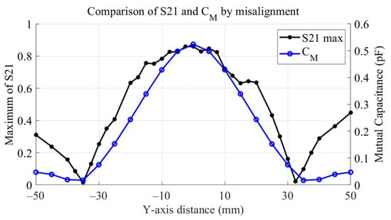
Figure 8.
S21 and mutual capacitance by Y-axis distance sweep.
Table 4.
Summary of S21 peak and capacitance by y-axis distance sweep.
As discussed in a previous study [29], this phenomenon occurs when the mutual capacitance CM formed between the transmitter and receiver converges to zero. The CM is determined by the interaction between the main coupling capacitances C23 and C14 and the cross-coupling capacitances. This relationship can be expressed as shown in Equation (7). The cross-coupling capacitances correspond to C13 and C24 in Equation (1).
In other words, when the product of the main coupling capacitances Cmc and the product of the cross-coupling capacitances Ccc become equal, the mutual capacitance CM converges to zero. Based on this principle, it can also be observed that the null-power points in Figure 8 occurred when CM approached zero.
4. Conclusions
A theoretical design of a four-plate parallel DCPT coupler applicable to mobile robot-level wireless charging is provided. This design includes the PEC design, incorporating the coupler’s loss resistance, and the derivation process of the scattering matrix for each network. The terms of the scattering matrix for each network were expressed in impedance form, allowing the overall scattering matrix of the proposed PEC to be defined through equation simplification. Valid mutual capacitance values were derived from the scattering matrix calculations of the PEC. This was verified by comparing with the results of 3D full-wave simulations. When the receiver’s displacement was 0 mm, the transmission coefficient results from the PEC matched those from the 3D full-wave simulation.
Additionally, changes in electromagnetic characteristics due to the misalignment of the transmitter and receiver of the four-plate parallel DCPT coupler were observed. The S21 and mutual capacitance were compared as the receiver moved between −50 mm and 50 mm along the y-axis. Null-power regions, where the power transmission efficiency sharply decreased, occurred at two points: −35 mm and 32.5 mm. The change in S21 showed a similar trend to the mutual capacitance. The parallel structure of the CPT coupler presented in this study has high mutual capacitance and strong coupling when the transmitter and receiver are aligned, but it is vulnerable to null-power regions.
A theoretical design method for the relatively under-researched DCPT coupler is provided. In the future, theoretical analysis of equivalent circuit models could be an approach to analyzing external factors that induce changes in the electromagnetic characteristics of wireless power transfer couplers. Further research is needed to closely analyze and improve structural alternatives for null-power regions occurring in the four-plate parallel DCPT structure.
Author Contributions
Conceptualization, S.P. and H.B.; methodology, S.P.; software, H.B.; validation, H.B.; formal analysis, H.B.; investigation, H.B.; resources, S.P.; data curation, H.B.; writing—original draft preparation, H.B.; writing—review and editing, H.B.; visualization, H.B.; supervision, S.P.; project administration, S.P.; funding acquisition, S.P. All authors have read and agreed to the published version of the manuscript.
Funding
This results was supported by the “Regional Innovation Strategy (RIS)” through the National Research Foundation of Korea (NRF) funded by the Ministry of Education (MOE) (2021RIS-004), and This work was supported by the Soonchunhyang University Research Fund.
Institutional Review Board Statement
Not applicable.
Informed Consent Statement
Not applicable.
Data Availability Statement
The raw data supporting the conclusions of this article will be made available by the authors upon request.
Conflicts of Interest
The authors declare no conflicts of interest.
References
- Liu, W.; Chau, K.T.; Tian, X.; Wang, H.; Hua, Z. Smart Wireless Power Transfer—Opportunities and Challenges. Renew. Sustain. Energy Rev. 2023, 180, 113298. [Google Scholar] [CrossRef]
- Azad, A.; Tavakoli, R.; Pratik, U.; Varghese, B.; Coopmans, C.; Pantic, Z. A Smart Autonomous WPT System for Electric Wheelchair Applications With Free-Positioning Charging Feature. IEEE J. Emerg. Sel. Top. Power Electron. 2020, 8, 3516–3532. [Google Scholar] [CrossRef]
- Meile, L.; Ulrich, A.; Magno, M. Wireless Power Transmission Powering Miniaturized Low Power IoT Devices: A Revie. In Proceedings of the 2019 IEEE 8th International Workshop on Advances in Sensors and Interfaces (IWASI), Otranto, Italy, 13–14 June 2019; pp. 312–317. [Google Scholar] [CrossRef]
- Colmiais, I.; Dinis, H.; Mendes, P.M. Long-Range Wireless Power Transfer for Moving Wireless IoT Devices. Electronics 2024, 13, 2550. [Google Scholar] [CrossRef]
- Choi, K.W.; Aziz, A.A.; Setiawan, D.; Tran, N.M.; Ginting, L.; Kim, D.I. Distributed Wireless Power Transfer System for Internet of Things Devices. IEEE Internet Things J. 2018, 5, 2657–2671. [Google Scholar] [CrossRef]
- Deng, Z.; Hu, H.; Su, Y.; Chen, F.; Xiao, J.; Tang, C.; Lin, T. Design of a 60-kW EV Dynamic Wireless Power Transfer System With Dual Transmitters and Dual Receivers. IEEE J. Emerg. Sel. Top. Power Electron. 2024, 12, 316–327. [Google Scholar] [CrossRef]
- Huh, J.; Lee, S.W.; Lee, W.Y.; Cho, G.H.; Rim, C.T. Narrow-Width Inductive Power Transfer System for Online Electrical Vehicles. IEEE Trans. Power Electron. 2011, 26, 3666–3679. [Google Scholar] [CrossRef]
- Fujita, T.; Yasuda, T.; Akagi, H. A Dynamic Wireless Power Transfer System Applicable to a Stationary System. IEEE Trans. Ind. Applicat. 2017, 53, 3748–3757. [Google Scholar] [CrossRef]
- Villa, J.; Sanz, J.; Acerete, R.; Perie, M. Design Considerations for WPT Dynamic Charging Applications. In Proceedings of the 2019 AEIT International Conference of Electrical and Electronic Technologies for Automotive (AEIT AUTOMOTIVE), Turin, Italy, 2–4 July 2019; IEEE: Torino, Italy, 2019; pp. 1–6. [Google Scholar] [CrossRef]
- Zhao, J.; Cai, T.; Duan, S.; Feng, H.; Chen, C.; Zhang, X. A General Design Method of Primary Compensation Network for Dynamic WPT System Maintaining Stable Transmission Power. IEEE Trans. Power Electron. 2016, 31, 8343–8358. [Google Scholar] [CrossRef]
- Lin, C.-H.; Amir, M.; Tariq, M.; Shahvez, M.; Alamri, B.; Alahmadi, A.; Siddiqui, M.; Beig, A. Comprehensive Analysis of IPT v/s CPT for Wireless EV Charging and Effect of Capacitor Plate Shape and Foreign Particle on CPT. Processes 2021, 9, 1619. [Google Scholar] [CrossRef]
- Wang, J.; Hu, M.; Cai, C.; Lin, Z.; Li, L.; Fang, Z. Optimization Design of Wireless Charging System for Autonomous Robots Based on Magnetic Resonance Coupling. AIP Adv. 2018, 8, 055004. [Google Scholar] [CrossRef]
- Liu, H.; Huang, X.; Tan, L.; Guo, J.; Wang, W.; Yan, C.; Xu, C. Dynamic Wireless Charging for Inspection Robots Based on Decentralized Energy Pickup Structure. IEEE Trans. Ind. Inf. 2018, 14, 1786–1797. [Google Scholar] [CrossRef]
- Jo, H.; Seo, S.; Kim, J.; Bien, F. A Coreless Track-Type Seamless Wireless Charging System Using Co-Planar Wires Enabling Quasi-Free Planar Movements for Mobile Logistics Robots. Appl. Energy 2024, 375, 123943. [Google Scholar] [CrossRef]
- Kurs, A.; Karalis, A.; Moffatt, R.; Joannopoulos, J.D.; Fisher, P.; Soljačić, M. Wireless Power Transfer via Strongly Coupled Magnetic Resonances. Science 2007, 317, 83–86. [Google Scholar] [CrossRef] [PubMed]
- Shah, I.A.; Cho, Y.; Yoo, H. Safety Evaluation of Medical Implants in the Human Body for a Wireless Power Transfer System in an Electric Vehicle. IEEE Trans. Electromagn. Compat. 2021, 63, 681–691. [Google Scholar] [CrossRef]
- Christ, A.; Douglas, M.; Nadakuduti, J.; Kuster, N. Assessing Human Exposure to Electromagnetic Fields From Wireless Power Transmission Systems. Proc. IEEE 2013, 101, 1482–1493. [Google Scholar] [CrossRef]
- Tarusawa, Y.; Ohshita, K.; Suzuki, Y.; Nojima, T.; Toyoshima, T. Experimental Estimation of EMI From Cellular Base-Station Antennas on Implantable Cardiac Pacemakers. IEEE Trans. Electromagn. Compat. 2005, 47, 938–950. [Google Scholar] [CrossRef]
- Hikage, T.; Kawamura, Y.; Nojima, T.; Cabot, E. Numerical Assessment Methodology for Active Implantable Medical Device EMI Due to Magnetic Resonance Wireless Power Transmission Antenna. In Proceedings of the International Symposium on Electromagnetic Compatibility-EMC EUROPE, Rome, Italy, 17–21 September 2012; IEEE: Rome, Italy, 2012; pp. 1–6. [Google Scholar] [CrossRef]
- Hikage, T.; Kawamura, Y.; Nojima, T.; Koike, B.; Fujimoto, H.; Toyoshima, T. Active Implantable Medical Device EMI Assessments for Electromagnetic Emitters Operating in Various RF Bands. In Proceedings of the 2011 IEEE MTT-S International Microwave Workshop Series on Innovative Wireless Power Transmission: Technologies, Systems, and Applications, Kyoto, Japan, 12–13 May 2011; IEEE: Uji, Japan, 2011; pp. 109–112. [Google Scholar] [CrossRef]
- Cruciani, S.; Campi, T.; Maradei, F.; Feliziani, M. Wireless Charging in Electric Vehicles: EMI/EMC Risk Mitigation in Pacemakers by Active Coils. In Proceedings of the 2019 IEEE PELS Workshop on Emerging Technologies: Wireless Power Transfer (WoW), London, UK, 18–21 June 2019; IEEE: London, UK, 2019; pp. 173–176. [Google Scholar] [CrossRef]
- International Commission on Non-Ionizing Radiation Protection. Guidelines for Limiting Exposure to Electromagnetic Fields (100 kHz to 300 GHz). Health Phys. 2020, 118, 483–524. [Google Scholar] [CrossRef]
- Bang, K.-W.; Park, S.-W.; Bae, H.-G.; Lee, B.-Y.; Oh, H.-M.; Park, C.-U.; Baek, S.-H. Evaluation of Electromagnetic Exposure in Wireless Power Transfer Systems for Electric Vehicles. J. Electromagn. Eng. Sci. 2024, 24, 34–41. [Google Scholar] [CrossRef]
- Liu, C.; Hu, A.P. Steady State Analysis of a Capacitively Coupled Contactless Power Transfer System. In Proceedings of the 2009 IEEE Energy Conversion Congress and Exposition, San Jose, CA, USA, 20–24 September 2009; IEEE: San Jose, CA, USA, 2009; pp. 3233–3238. [Google Scholar] [CrossRef]
- Wang, C.; Zhu, C.; Wei, G.; Feng, J.; Jiang, J.; Lu, R. Design of Compact Three-Phase Receiver for Meander-Type Dynamic Wireless Power Transfer System. IEEE Trans. Power Electron. 2020, 35, 6854–6866. [Google Scholar] [CrossRef]
- Song, B.; Cui, S.; Li, Y.; Zhu, C. A Narrow-Rail Three-Phase Magnetic Coupler With Uniform Output Power for EV Dynamic Wireless Charging. IEEE Trans. Ind. Electron. 2021, 68, 6456–6469. [Google Scholar] [CrossRef]
- Zhou, W.; Li, M.; Zhang, Q.; Li, Z.; Xie, S.; Fan, Y. Potential and Challenges of Capacitive Power Transfer Systems for Wireless EV Charging: A Review of Key Technologies. Green Energy Intell. Transp. 2024, 3, 100174. [Google Scholar] [CrossRef]
- Zhang, Y.; Chen, S.; Li, X.; Yan, Z.; Tang, Y. A Compact Dynamic Wireless Power Transfer System via Capacitive Coupling Achieving Stable Output. In Proceedings of the 2020 IEEE 9th International Power Electronics and Motion Control Conference (IPEMC2020-ECCE Asia), Nanjing, China, 29 November–2 December 2020; IEEE: Nanjing, China, 2020; pp. 3269–3275. [Google Scholar] [CrossRef]
- Wang, Y.; Zhang, H.; Lu, F. Review, Analysis, and Design of Four Basic CPT Topologies and the Application of High-Order Compensation Networks. IEEE Trans. Power Electron. 2022, 37, 6181–6193. [Google Scholar] [CrossRef]
- Bang, K.; Bae, H.; Park, S. Resonant-Based Wireless Power Transfer System Using Electric Coupling for Transparent Wearable Devices and Null Power Points. Sensors 2023, 23, 1535. [Google Scholar] [CrossRef] [PubMed]
- Zhang, H.; Lu, F.; Hofmann, H.; Liu, W.; Mi, C. A 4-Plate Compact Capacitive Coupler Design and LCL-Compensated Topology for Capacitive Power Transfer in Electric Vehicle Charging Applications. IEEE Trans. Power Electron. 2016, 31, 8541–8551. [Google Scholar] [CrossRef]
- Mahdi, H.; Hattori, R.; Hoff, B.; Uezu, A.; Akiyoshi, K. Design Considerations of Capacitive Power Transfer Systems. IEEE Access 2023, 11, 57806–57818. [Google Scholar] [CrossRef]
- Erel, M.Z.; Bayindir, K.C.; Aydemir, M.T. A New Capacitive Coupler Design for Wireless Capacitive Power Transfer Applications. Eng. Sci. Technol. Int. J. 2023, 40, 101364. [Google Scholar] [CrossRef]
- Li, S.; Liu, Z.; Zhao, H.; Zhu, L.; Shuai, C.; Chen, Z. Wireless Power Transfer by Electric Field Resonance and Its Application in Dynamic Charging. IEEE Trans. Ind. Electron. 2016, 63, 6602–6612. [Google Scholar] [CrossRef]
- Lu, F.; Zhang, H.; Hofmann, H.; Mei, Y.; Mi, C. A Dynamic Capacitive Power Transfer System with Reduced Power Pulsation. In Proceedings of the 2016 IEEE PELS Workshop on Emerging Technologies: Wireless Power Transfer (WoW), Knoxville, TN, USA, 4–6 October 2016; IEEE: Knoxville, TN, USA, 2016; pp. 60–64. [Google Scholar] [CrossRef]
- Zhang, J.; Yao, S.; Pan, L.; Liu, Y.; Zhu, C. A Review of Capacitive Power Transfer Technology for Electric Vehicle Applications. Electronics 2023, 12, 3534. [Google Scholar] [CrossRef]
- Jeong, S.Y.; Kwak, H.G.; Jang, G.C.; Rim, C.T. Living Object Detection System Based on Comb Pattern Capacitive Sensor for Wireless EV Chargers. In Proceedings of the 2016 IEEE 2nd Annual Southern Power Electronics Conference (SPEC), Auckland, New Zealand, 5–8 December 2016; IEEE: Auckland, New Zealand, 2016; pp. 1–6. [Google Scholar] [CrossRef]
- Lu, J.; Zhu, G.; Mi, C.C. Foreign Object Detection in Wireless Power Transfer Systems. IEEE Trans. Ind. Appl. 2022, 58, 1340–1354. [Google Scholar] [CrossRef]
- Lee, T.-S.; Huang, S.-J.; Tai, C.-C.; Chen, R.-Y.; Jiang, B.-R. Design of Wireless Power Transfer for Dynamic Power Transmission with Position-Detection Mechanism. In Proceedings of the 2015 IEEE International Conference on Industrial Technology (ICIT), Seville, Spain, 17–19 March 2015; IEEE: Seville, Spain, 2015; pp. 976–981. [Google Scholar] [CrossRef]
- Herpers, C.; Rouse, C.D. Matrix Persymmetry Analysis for Misalignment and Foreign Object Detection in Resonant Capacitive Power Transfer. IEEE Access 2024, 12, 65078–65087. [Google Scholar] [CrossRef]
- Pahlavan, S.; Shooshtari, M.; Jafarabadi Ashtiani, S. Star-Shaped Coils in the Transmitter Array for Receiver Rotation Tolerance in Free-Moving Wireless Power Transfer Applications. Energies 2022, 15, 8643. [Google Scholar] [CrossRef]
- Pahlavan, S.; Jafarabadi-Ashtiani, S.; Mirbozorgi, S.A. Maze-Based Scalable Wireless Power Transmission Experimental Arena for Freely Moving Small Animals Applications. IEEE Trans. Biomed. Circuits Syst. 2024, 1–10. [Google Scholar] [CrossRef] [PubMed]
- Hyun, S.; Bae, H.; Park, S. Characteristics Analysis of Resonance-Based Wireless Power Transfer Using Magnetic Coupling and Electric Coupling. Eng. Sci. Technol. Int. J. 2023, 42, 101419. [Google Scholar] [CrossRef]
- Luo, B.; Mai, R.; Guo, L.; Wu, D.; He, Z. LC–CLC Compensation Topology for Capacitive Power Transfer System to Improve Misalignment Performance. IET Power Electron. 2019, 12, 2626–2633. [Google Scholar] [CrossRef]
Disclaimer/Publisher’s Note: The statements, opinions and data contained in all publications are solely those of the individual author(s) and contributor(s) and not of MDPI and/or the editor(s). MDPI and/or the editor(s) disclaim responsibility for any injury to people or property resulting from any ideas, methods, instructions or products referred to in the content. |
© 2025 by the authors. Licensee MDPI, Basel, Switzerland. This article is an open access article distributed under the terms and conditions of the Creative Commons Attribution (CC BY) license (https://creativecommons.org/licenses/by/4.0/).