Article

A Virtual Synchronous Generator Control Strategy Based on Transient Damping Compensation and Virtual Inertia Adaptation

1
School of Automation and Information Engineering, Sichuan University of Science & Engineering, Yibin 644000, China
2
Zonergy Co., Ltd., Zigong 643000, China
3
Hydrogen Energy and Multi-Energy Complementary Microgrid Engineering Technology Research Center of Sichuan Province, Mianyang 621000, China
*
Author to whom correspondence should be addressed.
Appl. Sci. 2025, 15(2), 728; https://doi.org/10.3390/app15020728
Submission received: 3 October 2024 / Revised: 2 January 2025 / Accepted: 3 January 2025 / Published: 13 January 2025

Abstract

:
To mitigate the challenges posed by transient oscillations and steady-state deviations in the traditional virtual synchronous generator (TVSG) that is subjected to active power and grid frequency disturbances, a VSG control strategy based on Transient Damping Compensation and Virtual Inertia Adaptation is presented. Initially, a closed-loop small-signal model for the grid-connected active power loop (APL) of the TVSG is constructed, which highlights the contradiction between the dynamic and static characteristics of TVSG output power through the analysis of root locus distribution trends. Secondly, a VSG control strategy based on Transient Damping Compensation (TDC) is proposed. The influence of APL system parameters introduced by TDC on system stability is qualitatively analyzed based on pole distribution trends and frequency response, and a comprehensive parameter design scheme is presented. In addition, based on the TDC algorithm, an improved virtual inertia adaptive strategy utilizing the Inverse Square Root Unit (ISRU) approach is designed, and the tuning range of parameters is provided. Finally, simulations and experiments verify that the proposed strategy exhibits superior active response performance and transient oscillation suppression capabilities, effectively eliminating active steady-state deviations caused by frequency disturbances in the power grid.

1. Introduction

With the widespread integration of distributed energy sources supply to the power grid, the penetration rate of power electronic equipment in the electronic power system is gradually increased. This phenomenon leads to the low-inertia, weak damping, and weak frequency support characteristics of the traditional power system [1,2], significantly affecting its stability and security. To address the issue of grid instability and frequency oscillations arising from the high proportion of renewable energy [3,4], some scholars, drawing from the operational characteristics of synchronous generators, introduced virtual inertia and damping links through the simulation of its power swing equation. Based on this, VSG control technology is proposed [5,6]. This control strategy makes the grid-connected converter capable of primary frequency regulation (PFR) and one-time voltage regulation, improving the anti-interference ability of the system [7].
Introducing virtual inertia and damping mechanisms is an effective strategy for improving the system’s PFR capability and enhancing the dynamic stability of the system’s frequency. However, the traditional virtual inertia control strategy alters the system characteristics of the TVSG’s APL from first-order to second-order oscillatory characteristics, resulting in transient oscillations within the VSG’s grid-connected system during active power and grid frequency disturbances [8], weakening the dynamics of the APL system. The introduction of damping mechanisms can be viewed as an equivalent to increasing PFR parameters; however, larger damping parameters may result in greater steady-state deviations within the APL [9,10]. Therefore, the TVSG based on a fixed damping strategy contradicts transient performance and steady-state performance, which cannot eliminate the problem of active steady-state deviation caused by damping characteristics while suppressing transient oscillation [11].
Researchers have embarked on an extensive array of studies to tackle the identified technical difficulties and refine the active power response performance within the TVSG. These investigations are categorically divided into two distinct approaches: the adaptive virtual inertia damping methodology [12] and the equivalent damping ratio strategy [13]. To enhance the response rate of TVSG steady-state frequency tracking, a VSG control strategy based on the intermittent variation in virtual inertia is proposed in [14]. However, this intermittent variation introduces redundant nonlinear characteristics that adversely affect the system’s stability. The authors of [15] introduce a fuzzy controller into the VSG power swing equation to enhance the system’s response performance during transient processes while also addressing the adverse effects of discontinuous virtual inertia settings on system stability. The authors of [16,17] propose a VSG control strategy incorporating synergistic adaptive virtual inertia and damping parameters, which not only enhances the transient stability of the power outputs of the VSG system but also further mitigates frequency deviations resulting from active power disturbances, thereby improving the dynamics of the APL system. However, it is important to note that most aforementioned studies are predicated on stable operating conditions of the grid, concentrating on enhancing system stability under small disturbances, and thus failing to address the steady-state deviations arising from the coupling of damping and frequency modulation parameters. Furthermore, the improper selection of adaptive parameter ranges can adversely impact the steady-state performance of VSG grid-connected systems.
In the context of equivalent damping ratio methodologies, the authors of [18] conducted a qualitative analysis of the fault limit clearing time and the fault limit clearing angle in the VSG and established the influence mechanisms between control parameters and the transient characteristics of the APL system in the TVSG. Based on this, a control strategy with flexible parameter selection to optimize the transient performance of the VSG is proposed. However, if the fault persists for an extended duration, the VSG will still encounter the challenge of desynchronization with the grid. The authors of [19] incorporate first-order differential compensation into the power swing equation of the VSG, effectively suppressing transient oscillations within the system without impacting the steady outputs of the APL system in the TVSG during grid-connected operation. However, this control strategy neglects the influence of high-frequency interference signals on system stability. The authors of [20,21] introduce the first-order lead–lag compensator within the VSG damping feedback loop, enhancing the dynamics of the VSG while mitigating high-frequency interference effects during transient disturbances. However, this scheme does not describe the dominant pole assignment process for the APL. The authors of [22] introduce band-pass damping feedback control into the APL to construct transient damping managed by the VSG, enhancing the system’s transient oscillation suppression performance. However, incorporating band-pass damping transforms the APL controlled by the VSG from a second-order system to a fourth-order system, which complicates the parameter design and may lead to power shocks.
In addition, other scholars have explored controlling inertia and damping parameters in the APL by introducing fuzzy logic [23] and robust control [24]. In [25], a VSG control strategy based on fuzzy logic is provided, which effectively makes the dynamics of the APL more robust with increased adaptivity of damping and inertia. In [26], an adaptive control strategy predicated on the radial basis function (RBF) algorithm is applied. By introducing the RBF neural network into the APL system, this strategy adaptively adjusts the virtual inertia and damping coefficient, effectively enhancing the system’s dynamic performance. However, the design of the fuzzy controller requires experienced personnel to verify its efficacy, and the difficulty of the design increases with the complexity of the electrical power system. Control strategies developed using neural network concepts require substantial data and time to assess their effectiveness, presenting challenges such as high sample dependency and a complex algorithmic structure.
In view of the above problems, this article firstly establishes a closed-loop small-signal model of the TVSG under given power and grid frequency variations, analyzes the transient oscillation mechanism of the TVSG combined with root locus, and reveals the contradiction between the transient performance and steady-state performance of the TVSG control strategy. Secondly, a VSG control strategy incorporating Transient Damping Compensation (TDC) and virtual inertia adaptation is proposed. Utilizing the pole distribution trend and frequency response, the influence of control parameters introduced by TDC on system stability is qualitatively analyzed, and a tuning scheme for related control parameters is provided based on the dominant pole method. Subsequently, an improved virtual inertia adaptive strategy based on the ISRU approach rate is designed based on the TDC algorithm, providing the value range for adaptive changes in virtual inertia to optimize the dynamics of the TDC-VSG. Finally, the proposed strategy’s effectiveness is verified through Matlab/Simulink simulations and Hardware-in-the-Loop (HIL) semi-physical experiments.

2. Basic Principles of the TVSG

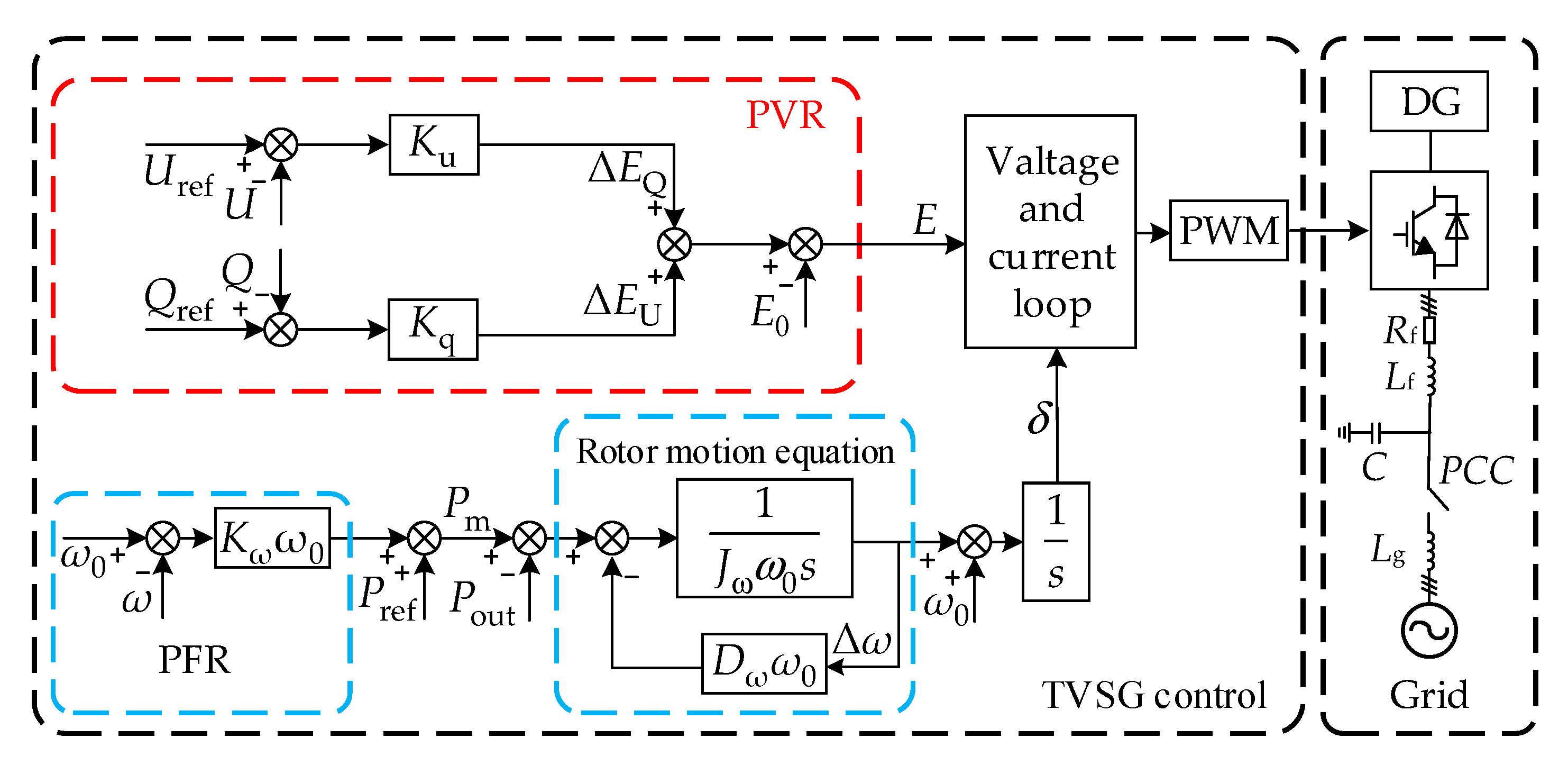
Combined with typical grid-connected converter topology, power swing equation, and electromagnetic equation of the SG, the TVSG main circuit topology and its simplified structure are constructed, as shown in Figure 1.
Predicated on the second-order mathematical model of the traditional SG, the mechanical equation for the APL controller in the TVSG [19] is presented in Equation (1):
P m P out = J ω ω 0 d ω d t + D ω ω 0 ( ω ω 0 )
where Jω is the virtual inertia; Dω is the damping coefficient; ω is the virtual angular frequency; ω0 is the rated angular frequency; and Pm and Pout are, respectively, designated as the VSG’s virtual machine power and output active power.
The virtual mechanical power Pm is composed of the active power regulation instruction Pref and the frequency regulation power output by the PFR characteristic, as shown in the following equation:
P m = P ref + K ω ω 0 ( ω 0 ω )
where Kω is designated as the FPR coefficient.
Based on the operational principles of the traditional SG reactive power regulator, the primary voltage regulation (PVR) equation for the voltage amplitude command E, emitted by the TVSG, is presented as follows:
E = E 0 + Δ E Q + Δ E U = E 0 + K q ( Q ref Q ) + K u ( U ref U )
where E0 is the TVSG’s no-load potential; ΔEQ is the reactive power regulation deviation; ΔEU is the voltage regulation deviation; Kq is the power adjustment coefficient; Qref is the reactive power adjustment instruction; Q is the instantaneous reactive power value of the TVSG output; Ku is the voltage regulation coefficient; Uref is the voltage regulation instruction; and U is the instantaneous terminal voltage.
This paper primarily optimizes the dynamics and transient stability of the APL for the TVSG, achieving decoupling control of active and reactive power in the VSG power control link under inductive line impedance conditions [
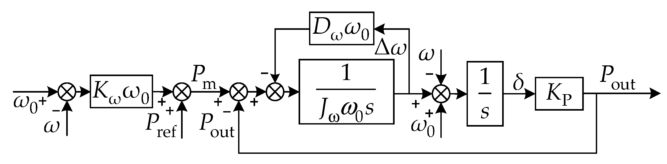
10]. Consequently, the PVR characteristics of the VSG reactive power loop and voltage–current double closed-loop control strategy are not extensively discussed. Predicated on the above analysis, the TVSG control block diagram is illustrated in Figure 2.
The virtual inertia and damping characteristics in the TVSG system are primarily reflected in the APL characteristics of its power swing equation, specifically the P-ω characteristics. Based on Equations (1) and (2), the VSG’s open-loop transfer function is derived as follows:
G P - ω = Δ ω Δ P = 1 J ω ω 0 s + K ω ω 0 + D ω ω 0 = K A τ s + 1
K A = 1 D ω ω 0 + K ω ω 0 τ = J ω D ω + K ω
where KA represents the power droop coefficient; τ is the inertial time constant. Equation (4) illustrates that GP-ω serves as a first-order inertial component. Considering the inherent inertia transition characteristic of τ, changes in Δω exhibit a lag relative to ΔP, with the extent of this lag contingent upon parameters such as Jω, Dω, and Kω. The interaction between Dω and Kω determines the extent of steady-state deviation in the TVSG’s grid-connected outputs. The selection of Kω is primarily governed by the system’s rated capacity, and it must also adhere to the criterion that a 100% variation in active power results in a frequency deviation not exceeding ±1% of the rated frequency, corresponding to Kω = ΔPref/(ω0Δω). Consequently, the effect of Dω on the steady-state output characteristics of grid-connected VSG systems can be evaluated by adjusting its magnitude. The impact of Dω on the steady-state output characteristics of the APL system in the TVSG can be assessed by varying the magnitude of Dω.

3. Transient Oscillation Mechanism Analysis of the TVSG

3.1. VSG Steady-State Power Characteristics and Existing Problems

This article focuses on the analysis of the APL with low-frequency characteristics. It can be inferred from the frequency analysis that the voltage control loop presents followability at the low frequency [22], and the adjustment time of the voltage and current inner loop is significantly faster than that of the APL. Hence, the influence of the inner loops on APL outputs is not considered in this article.
Predicated on the TVSG grid-connected operation circuit depicted in Figure 1, the output power expression [27] is derived as follows:
P out = 3 E U g sin δ X 3 E U g δ X Q out = 3 U g E cos δ U g X 3 U g E U g X
where Ug is the designator for the grid’s phase voltage; δ is the angular disparity in the phase between the TVSG and the grid voltage; and X is the notation for the line’s equivalent impedance. Constructed by integrating Equations (1), (2), and (6), the small-signal control block diagram of the APL system in the TVSG is illustrated in Figure 3.
As illustrated in Figure 3, KP = 3EUg/X, when the TVSG operates in grid-connected mode, the closed-loop transfer function of its active output power Pout [28] is presented in the following equation:
P out = K P J ω ω 0 s 2 + ( K ω + D ω ) ω 0 s + K P P ref + K P ω 0 ( J ω s + K ω + D ω ) J ω ω 0 s 2 + ( K ω + D ω ) ω 0 s + K P ( ω ω 0 ) = G P ( s ) P ref + G ω ( s ) ( ω ω 0 )
where GP(s) is the closed-loop transfer function of the APL under given power disturbances; Gω(s) is the closed-loop transfer function of the APL when the grid frequency is disturbed.
Based on Equation (7), when the TVSG operates in grid-connected mode, the steady-state output Pouts is expressed by the following equation.
P outs = lim s 0 K P J ω ω 0 s 2 + ( K ω + D ω ) ω 0 s + K P P ref + K P ω 0 ( J ω s + K ω + D ω ) J ω ω 0 s 2 + ( K ω + D ω ) ω 0 s + K P ( ω ω 0 ) = P ref ( K ω ω 0 + D ω ω 0 ) ( ω ω 0 )
As illustrated in Equation (8), under the influence of the damping coefficient, the Pouts of the TVSG include a steady-state active power deviation (Dωω0 + Kωω0)(ω0ω) resulting from the coupling of Dω and Kω. The damping power feedback control of the TVSG essentially simplifies the PFR and damping feedback control into a droop control mechanism. Given the differing purposes of the PFR and damping feedback control, a reasonable Kω may lead to the TVSG lacking necessary damping characteristics, resulting in significant power oscillations within the system. An appropriate Dω may also result in an undesired PFR coefficient, failing to satisfy the PFR requirement of the TVSG.

3.2. VSG Dynamic Power Characteristics and Existing Problems

Based on Equation (7), the APL closed-loop transfer function GPP(s) of the APL system in the TVSG is derived as follows [29]:
G PP ( s ) = Δ P out Δ P ref = K P J ω ω 0 s 2 + ( K ω ω 0 + D ω ω 0 ) s + K P
As illustrated in Equation (9), GPP(s) is a second-order oscillation system, and the dynamic response performance of GPP(s) is influenced by the two conjugate poles s1 and s2 in Equation (9). The closed-loop pole positions of GPP(s) can be modified by adjusting Jω and Dω to optimize the dynamic response characteristics of the TVSG. To further elaborate on the influence of Jω and Dω on the TVSG’s dynamic response characteristics, the closed-loop pole distribution trend of GPP(s) gradually increasing from 0 to 100 under different J values is shown in Figure 4 and the main circuit parameters of the TVSG are shown in Table 1.
As shown in Figure 4, GPP(s) exhibits a pair of conjugate poles, s1 and s2. When Dω follows the same trend, a larger value of Jω results in the starting positions of s1 and s2 being closer to the imaginary axis. This phenomenon reduces the damping ratio of the system, thereby weakening the stability and adjustment rate of the TVSG. When the virtual inertia Jω is constant, as Dω increases, s1 and s2 progressively transition into two real poles, following the trajectory indicated by the arrow. This causes the system characteristics of GPP(s) to shift from underdamped to overdamped, consequently increasing the adjustment time of the APL system in the TVSG.
According to the above analysis, when the TVSG is in grid-connected operation, the steady-state characteristic is determined by Dω and is independent of Jω, while the dynamic characteristics are related to the values of Dω and Jω. To satisfy the requirements for high damping characteristics and low power overshoot, selecting a large Dω may lead to significant steady-state deviation and a reduced system response rate. Conversely, to enhance the adjustment rate of the system, opting for a large Jω can aggravate the power overshoot issue and reduce system stability. Therefore, a contradiction arises between the dynamics and the steady-state performance in selecting Dω and Jω parameters.

4. TDC-VSG Control Strategy

To address the dynamic and static requirements of modern power systems for the VSG during grid-connected operation, this section focuses on damping the transient oscillations caused by active power and grid frequency perturbations. Additionally, it aims to correct the steady-state deviations that result from a fixed damping control strategy. A TDC-VSG control strategy is provided in this section, and a detailed analysis of its transient oscillation suppression performance and comprehensive parameter design methods are provided.

4.1. TDC-VSG Control Principle

To fully reflect the damping characteristics of the VSG during transient oscillations and mitigate the steady-state deviations attributed to these characteristics, a transient damping link based on a first-order differential approach is integrated into the damping feedback loop to enhance the transient stability of the APL system in the TVSG. The specific expression is as follows:
P D = D ω ω 0 s ( ω ω 0 )
Introducing differential links renders the damping circuit more susceptible to high-frequency interference signals and facilitates an increase in the harmonic components of the control signal [20]. Therefore, a first-order lead–lag link is incorporated into the APL to enhance the dynamics and high-frequency disturbance rejection of the TVSG damping feedback loop. The specific expression is as follows:
P D = D T ω 0 T T s T T s + 1 ( ω ω 0 )
where TT represents the attenuation time constant of the TDC-VSG; DT is the transient damping coefficient. Predicated on Equation (11), the block diagram of the TDC-VSG is shown in Figure 5.
The small-signal model of the APL in the TDC-VSG, considering given power and grid frequency variations, is derived from Figure 5 as follows:
G PTDC ( s ) = K P ( T T s + 1 ) T T J ω ω 0 s 3 + a 1 s 2 + b 1 s + K P G ω TDC ( s ) = K P ( ( T T s + 1 ) ( J ω ω 0 s + D T ω 0 + K ω ω 0 ) D T ω 0 ) T T J ω ω 0 s 3 + a 1 s 2 + b 1 s + K P
where GPTDC(s) is the closed-loop transfer function of the APL system in the TDC-VSG under given power variations, while GωTDC(s) is the closed-loop transfer function of the APL under frequency variations. Coefficient a1 = Jωω0 + TT (DTω0 + Kωω0), b1 = Kω + TTKP.
Based on Equation (12), the steady output active power ΔPouts of the APL system in the TDC-VSG during grid-connected operation can be expressed as follows:
Δ P outs = lim s 0 G PTDC ( s ) Δ P ref + G ω TDC ( s ) ( ω ω 0 ) = Δ P ref K ω ω 0 ( ω ω 0 )
By comparing Equation (8) with Equation (13), the damping characteristics of the TDC-VSG achieve a decoupling operation between the damping characteristics and the PFR characteristics during steady-state operation. As a result, the damping characteristics only affect the transient oscillation process, thus eliminating the steady-state deviation caused by the fixed damping control strategy.

4.2. Transient Performance Analysis of the TDC-VSG

Through the comparison and analysis of Equations (7) and (12), it becomes evident that the TDC-VSG introduces a zero point and a pole into the APL system; the location of the zero point is associated with TT. When TT is small, Equation (12) approximates Equation (7), leading to less pronounced damping characteristics of the TDC-VSG; hence, TT should not be excessively small.
To analyze the influence of control parameters TT and DT on the transient stability of the TDC-VSG, the pole distribution trend of GPTDP(s) under varying TT and DT is constructed in Figure 6.
Figure 6a shows that at TT = 0.5, the TDC-VSG’s real pole sT3 is near the imaginary axis. Similarly, poles sT1 and sT2 are also close to the imaginary axis, suggesting that the APL system is prone to oscillation. However, as DT increases, the real pole sT3 gradually moves away from the imaginary axis while remaining as a real pole, and sT1 and sT2 move closer to the real axis, resulting in enhanced stability performance of the dynamics of the system. At DT = 17.3, the dominant poles sT1 and sT2 transition from conjugate poles to real-axis poles, causing the TDC-VSG system to shift from underdamped to overdamped characteristics, significantly improving oscillation suppression performance, thereby validating the effectiveness of the TDC-VSG.
As shown in Figure 6b, when DT = 20, the new pole sT3 of the TDC-VSG rapidly approaches the imaginary axis with increasing TT. However, the system stability is primarily influenced by the conjugate poles sT1 and sT2, which are very close to the imaginary axis, preventing sT3 from becoming the dominant pole. Furthermore, as TT increases, the distance between the conjugate poles and the imaginary axis exhibits only minor changes initially and gradually approaches the imaginary axis later, indicating that the overall variation is limited. This results in a small change in the system’s damping ratio, suggesting that TT has minimal impact on the transient stability of the APL system in the TDC-VSG. Consequently, the transient stability of the APL system in the TDC-VSG is predominantly determined by the transient damping coefficient DT. Additionally, a large TT extends the transient oscillation process due to hysteresis characteristics; therefore, the selection of TT should not be too large, so this paper takes TT = 0.5.
To verify the impact of DT on system stability performance, the unit step response characteristic curve of the APL system in the TDC-VSG under given power and grid frequency variations is constructed based on Equation (12), as shown in Figure 7. It can be seen from Figure 7a that increasing DT enhances the power oscillation suppression characteristics of the system under active power disturbances. Figure 7b illustrates that introducing DT eliminates the steady-state deviation caused by the fixed damping control strategy under grid frequency variations; however, excessive transient damping DT prolongs the recovery time to the steady-state. Thus, the system’s dynamic response performance and stability can be enhanced through a reasonable configuration of DT. As illustrated in Figure 7c,d, when TT is small, the Transient Damping Compensation characteristic of the TDC-VSG is not pronounced, and the system continues to exhibit transient oscillations. When TT = 0.5, the system’s power oscillation can be effectively suppressed. However, further increasing TT prolongs the system’s recovery time, aligning with the theoretical analysis above.

4.3. Parameter Design of the TDC-VSG

Predicated on Equation (12), the closed-loop transfer function of the APL system in the TDC-VSG under given power variations is derived as follows:
Φ ( s ) = Δ P ref Δ P out _ G = K P ( T T s + 1 ) T T J ω ω 0 s 3 + a 1 s 2 + b 1 s + K P
Based on classical control principles and the theoretical analysis in Figure 6, the stability performance of the TDC-VSG is primarily influenced by the dominant poles sT1 and sT2. Thus, the transient damping parameter DT can be designed using the dominant pole method [29] and frequency domain analysis. Based on Equation (14), it can be deduced as follows:
Φ ( s ) = ( T T s + 1 ) k P ( T T s + 1 ) ( s 2 + 2 ξ ω s s + ω s 2 ) = ( T T s + 1 ) k P ( T T s + 1 ) ( s 2 + D T + K ω J ω s + 3 E U g J ω ω 0 X )
where kp is the coefficient; ξ is the damping ratio of the APL; and ωs is the natural frequency of the APL. The concrete expression of the damping ratio ξ and natural frequency ωs are shown as follows:
ξ = D T + K ω 2 ω 0 X 3 J ω E U g ω s = 3 E U g J ω ω 0 X
Based on classical control theory, analyzing the frequency domain index relationships of the TDC-VSG yields the expressions for phase angle margin γ and cutoff frequency ωc of the APL as follows:
γ = arctan 2 ξ 1 + 4 ξ 4 2 ξ 2 ω c = ω s 1 + 4 ξ 4 2 ξ 2
To ensure the transient stability of the APL system in the TDC-VSG, the transient damping coefficient DT must satisfy the phase angle margin of 30° < γ < 70°. Using Equations (16) and (17), the feasible region for DT is illustrated in Figure 8. Hence, this paper adopts γ = 57.3°, ξ ≈ 0.707, and DT ≈ 17.32.

5. Virtual Inertia Adaptive Control Strategy Based on TDC Algorithm

Section 3.2 highlights that Jω must be appropriately configured to improve the system’s frequency support capability. The relationship between Jω and frequency is demonstrated in Equations (18) and (19) as follows:
P ref P out ( D ω ω 0 + K ω ω 0 ) ( ω ω 0 ) J ω ω 0 = d ω d t
P ref P out J ω ω 0 d ω d t D ω ω 0 + K ω ω 0 = ( ω ω 0 )
From the preceding equation, when PrefPout − (Dωω0 + Kωω0)(ωω0) remains constant, an increase in the value of Jω significantly enhances the inhibitory effect on |dω/dt|. Similarly, when PrefPout is held constant, larger Jω correlates with a more pronounced inhibitory effect on |ωω0|.
To optimize the dynamics and the transient stability of the APL system in the TVSG, the TVSG adaptive control strategy [14] employs |dω/dt| to dynamically adjust the Jω in real time, and its specific expression is provided below:
J ω = J 0 , Δ ω × d ω d t 0 J 0 , d ω d t T J J 0 + K J d ω d t , Δ ω × d ω d t > 0 & d ω d t > T J
D = D 0 , Δ ω T D D 0 + K d Δ ω , Δ ω > T D
where J0 is the steady-state value of the virtual inertia; Tj is the threshold of inertia determination; KJ is the inertia compensation coefficient; TD is the judgment threshold of the damping coefficient; and Kd is the compensation coefficient of the damping coefficient.

5.1. Virtual Inertia Adaptive Control Strategy Based on ISRU

Nonetheless, the TVSG adaptive control strategy solely accounts for the frequency change rate of the APL system, overlooking the impact of network frequency disturbances on the system’s stability performance, and failing to address the instability issues arising from excessive Jω compensation. Consequently, building upon the traditional VSG adaptive control strategy, this paper introduces a virtual inertia adaptive control strategy that integrates the ISRU approach rate, further enhancing the VSG control’s transient stability. The specific mathematical expression is presented as follows:
J ω = J 0 , d ω d t T j J 0 + A K j d ω d t ω ω 0 ω ω 0 , d ω d t > T j A ( x ) = a x 1 + ( a x ) 2
where a is the adjustment coefficient of the ISRU function; A(x) is the ISRU function.
The variation trends of the ISRU function and its derivatives are illustrated in Figure 9. As a nonlinear function capable of facilitating soft switching continuous control, the ISRU function features a changing boundary that allows Jω to vary between J0 + Kj and J0Kj, thereby mitigating the instability issues associated with excessive inertia compensation coefficients. In comparison to the traditional virtual inertia compensation value Kj[(dω|ωω0|)/dt|ωω0|)], the virtual inertia adaptive control strategy incorporating the characteristics of the ISRU function, when a = 2, is capable of suppressing frequency deviations more swiftly and enhancing the frequency recovery rate.

5.2. Parameter Settings of the TDC-VSG Adaptive Control Strategy

The result of adjusting virtual inertia J0 is evident from the grid-connected block diagram of the TVSG presented in Figure 3. The open-loop transfer function TP(s) of the APL system is shown below:
T P ( s ) = 1 J ω K ω + D ω s + 1 1 s 3 E U g ω 0 X
At the cutoff angular frequency ωc of the APL, defined as ωc = 2πfcp, the amplitude of TP(s) for the TVSG equals 1, as illustrated by Equation (24):
| T P ( j 2 π f cq ) | = | 1 j J ω 2 π f cq K ω + D ω + 1 1 j 2 π f cq | 3 E U g X ω 0 = 1
Solving the above equation yields the following:
J ω = K ω + D ω 2 π f cp 3 E U g 2 π f cp ω 0 X ( K ω + D ω ) 2 1
To satisfy the virtual inertia requirements of the TVSG, the expression under the radical sign in Equation (25) should be greater than zero as shown below:
f cp 3 E U g 2 π ω 0 X ( K ω + D ω ) = f cp _ max 3.25
To ensure that the system phase margin γref > 45° and the cutoff frequency remains below 0.2 times the rated frequency [30], the following conditions must be satisfied:
γ = 180 + T P ( j 2 π f cq ) γ ref
By substituting Equation (23) into Equation (27), the following is obtained:
J K ω + D ω 2 π f cp cot γ ref
The J-fcp characteristic curve and phase angle margin constraint curve are delineated in accordance with Equations (25) and (28), as illustrated in Figure 10. Predicated on the selection area of Jω and fcp depicted in Figure 10, fcq_min = 2.30, allowing for the determination of the virtual inertia J0, which is selected as 0.9.
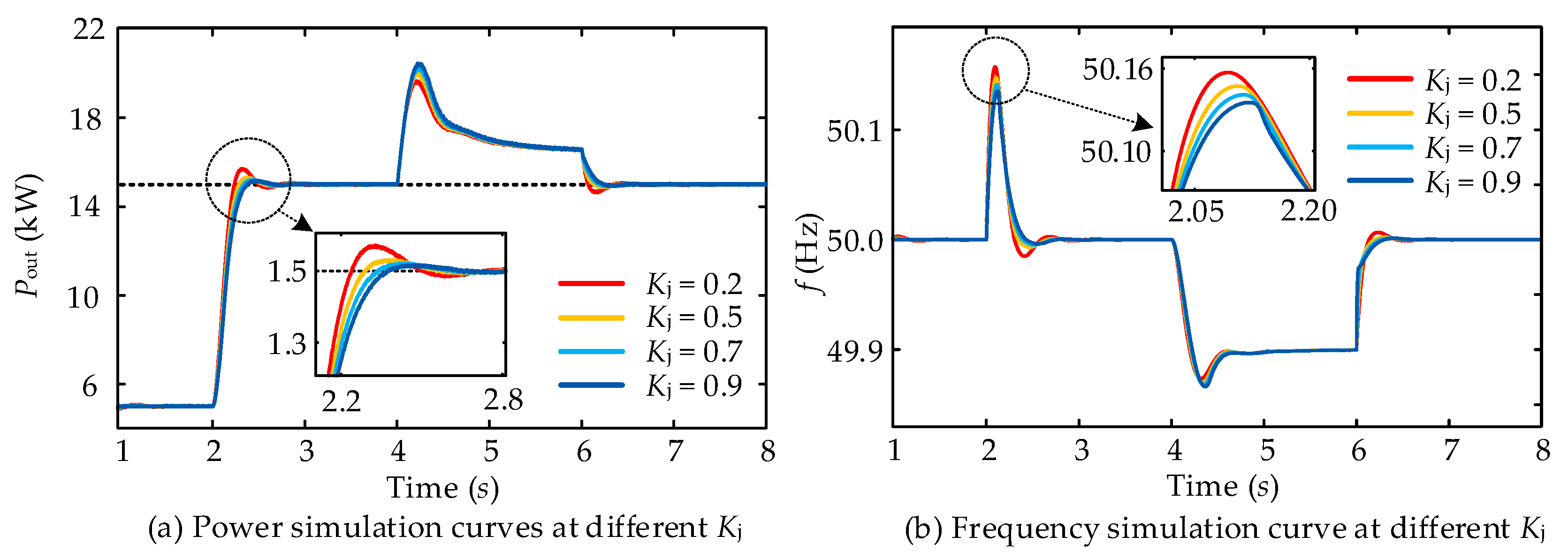
The appropriate compensation coefficient Kj and the virtual inertia switching threshold Tj are determined to enhance the dynamics and precision of the TDC-VSG adaptive control strategy. Figure 11 displays the system’s active power and frequency output characteristics under various control parameters.
The output characteristics of the system corresponding to various compensation coefficients are illustrated in Figure 11a. When Kj = 0.9, the control system demonstrates the most pronounced effectiveness in suppressing transient oscillations. The output characteristics of TDC-VSG under varying Tj are depicted in Figure 11b. As Tj decreases, the system performs better in mitigating power and frequency oscillations. Consequently, the optimal switching threshold Tj identified is 0.2.

6. Simulation Verification and Analysis

To demonstrate the feasibility of the TDC-VSG adaptive control strategy, a TDC-VSG converter model was constructed using Matlab/Simulink, and the specific structure of the TDC-VSG is illustrated in Figure 2. Utilizing this model, a comparative analysis of the control performance between TVSG control, traditional adaptive control, and TDC-VSG adaptive control strategies is conducted to highlight the superiority of the proposed strategy under conditions of given power and grid frequency variations. The parameters for the simulation are detailed in Table 2, and the specific simulation conditions are as follows: the given power adjustment command is from 5 kW to 15 kW at 2 s, while the grid frequency decreases from 50 Hz to 49.9 Hz at 4 s.

6.1. Characteristic Analysis of the TVSG

The simulation results for the TVSG in response to given power and grid frequency variations are presented in Figure 12. When Dω = 0, the efficient transient oscillations are observed under active power and grid frequency variations; in this scenario, the TVSG exhibits only steady-state deviations attributable to its PFR characteristics. With the increase of Dω, the transient oscillations and frequency fluctuations of the TVSG system are effectively mitigated. However, when Dω values are set at 5, 10, and 20, the corresponding steady-state deviations are approximately 2.5 kW, 3.4 kW, and 5.5 kW. The simulation findings are in agreement with the theoretical analysis. These indicate that while the TVSG effectively mitigates transient oscillations in the system by introducing fixed damping, it simultaneously results in significant steady-state deviations, thereby failing to satisfy the power system’s requirements for the TVSG active response characteristics.

6.2. Response Characteristic Analysis of the TDC-VSG Adaptive Control Strategy

Figure 13 illustrates the simulation results of the power and frequency curve for the TDC-VSG adaptive control strategy under given power and grid frequency disturbances, utilizing various adaptive compensation coefficients Kj with DT = 17.32. As evidenced by Figure 13, when Kj is small, the TDC-VSG closely approximates the traditional virtual inertia control strategy, exhibiting pronounced transient oscillations during given power and grid frequency variations. As Kj increases, the performance of the TDC-VSG in suppressing transient oscillations is significantly enhanced, further reducing the frequency variation rate and the frequency deviation of the TDC-VSG system.
Figure 14 illustrates the simulation results of the power and frequency curve for the TDC-VSG adaptive control strategy under given power and grid frequency variations, utilizing various DT with Kj = 0.9. This figure indicates that introducing transient damping significantly mitigates power and frequency oscillations of the TDC-VSG system while ensuring that the steady-state deviation remains unchanged during grid frequency variations. At DT = 17.32, the active power is stable and exhibits no oscillation. Based on this, the simulation findings are in agreement with the theoretical analysis presented in Figure 6, validating the effectiveness of the proposed TDC-VSG adaptive control strategy.

6.3. Analysis of the Dynamics of Different VSG Control Strategies

To further confirm the feasibility of the TDC-VSG adaptive control strategy, simulation experiments on active power response were conducted for TVSG control, traditional adaptive control, and TDC-VSG adaptive control strategies under optimal control parameters, as illustrated in Figure 15. The detailed control parameters are as follows: the damping coefficients for the TVSG control strategy are configured to Dω = 0 and Dω = Kω = 7.6; the compensation coefficients for traditional adaptive control are set at KJ = 0.2 and Kd = 10; and the compensation coefficient for the TDC-VSG adaptive control is set at KJ = 0.9, with the steady-state damping coefficient DT = 17.32.
As illustrated in Figure 15, at Dω = 0, the TVSG has obvious transient oscillation with power overshoots reaching 4.8 kW during active power disturbances. At Dω = 7.6, transient oscillations under the TVSG control strategy are effectively mitigated, reducing the power overshoot during given power variations to 1.6 kW. However, the steady-state deviation increases to 3 kW under grid frequency disturbances. Applying a traditional adaptive control strategy can significantly suppress power and frequency oscillations and reduce the frequency overshoot during given power variations. Nevertheless, the steady-state deviation during grid frequency variations reaches 4.7 kW, significantly compromising the steady-state performance of the TVSG system. The proposed TDC-VSG adaptive control strategy achieves a more rapid active response rate under given power and grid frequency variations. It effectively eliminates steady-state deviations caused by damping characteristics while suppressing transient oscillations, thereby enhancing the stability of grid-connected high-penetration distributed power supplies.
Figure 16 shows the voltage and current waveforms corresponding to various control strategies. As shown in the figure, the TVSG’s output current, which lacks damping characteristics, experiences significant transient oscillations. These oscillations are particularly pronounced during given power disturbances, grid frequency fluctuations, and the grid frequency recovery phase. Introducing fixed damping can effectively mitigate the transient oscillations in the current of the TVSG; however, the peak value of the current gradually increases during grid frequency disturbances. Introducing the adaptive compensation mechanism, the traditional adaptive control strategy significantly suppresses power and frequency oscillations in the output current during given power and grid frequency variations. Meanwhile, the peak value of the steady-state output current is greater in frequency drop scenarios.
The TDC-VSG adaptive control strategy proposed in this study effectively mitigates transient oscillations caused by active power disturbances. It is designed to restore stability rapidly during grid frequency disturbances. Importantly, this strategy does not negatively affect the steady-state outputs of the current in the TDC-VSG, thus enhancing the operational stability of distributed power supplies integrated into the grid.

6.4. Robustness Analysis of the TDC-VSG Under the Inductance Variation in the Power Grid

To verify the robustness of the TDC-VSG adaptive control strategy against variations in power grid inductance, the simulation is conducted under different inductance values while maintaining the same control parameters, as depicted in Figure 17. As illustrated in Figure 17, despite variations in power grid inductance values, the TDC-VSG adaptive control strategy significantly mitigates active power oscillations and frequency fluctuations within the system during given power and grid frequency variations. Consequently, the TDC-VSG control strategy demonstrates adaptability to varying power grid intensities, providing robust support for the stable operation of distributed power supplies connected to the grid.

7. Experimental Results and Analysis

To further prove the feasibility of the TDC-VSG adaptive control strategy, the VSG grid-connected experiments were conducted on the HIL platform and the details of the experimental platform are illustrated in Figure 18. The VSG main circuit topology is integrated into the Field Programmable Gate Array (FPGA) of the HIL real-time simulator, while the control program is executed on the Central Processing Unit (CPU) of the HIL, with an oscilloscope employed for output waveforms. The control parameters for the hardware experiment are as follows: the steady-state damping coefficients for the TVSG control strategy are set to Dω = Kω = 7.6; the compensation coefficients for the traditional adaptive control are configured as KJ = 0.2 and Kd = 10; the compensation coefficient for the TDC-VSG adaptive control is set at Kj = 0.9, with the steady-state damping coefficient designated as DT = 17.32. The specific experimental conditions are set as follows: In Test Condition 1, the reference power Pref increases from 0 kW to 15 kW at 7.5 s and subsequently decreases to 0 kW at 10 s. In Test Condition 2, the grid frequency drops from 50 Hz to 49.9 Hz.
Figure 19a,b illustrates that the experimental outcomes under given power and grid frequency variations align closely with the simulation results. When Dω = Kω = 7.6, significant transient oscillations occur within the TVSG control strategy, accompanied by steady-state deviations attributable to damping characteristics during grid frequency variations. The traditional adaptive control strategy significantly mitigates power and frequency oscillations under both disturbances; however, it further exacerbates the steady-state deviation during grid frequency variations. The TDC-VSG control strategy not only suppresses transient oscillations but also solves the issue of steady-state deviation resulting from damping characteristics, exhibiting a faster active response rate under both disturbances. The experimental results confirm the simulation findings, proving the feasibility of the TDC-VSG control strategy.

8. Conclusions

To address the challenge presented by the fact that the TVSG system struggles to balance transient oscillations and steady-state deviations resulting from active power and grid frequency disturbances, a VSG control strategy founded on Transient Damping Compensation and virtual inertia adaptation is provided. Through theoretical analysis, Matlab R2024a simulations, and semi-physical experimental validation, the following conclusions are drawn:
(1)
A theoretical framework for discussing the dynamic performance of TVSG outputs is provided, which helps to explain the reason for the transient oscillation of power outputs in the TVSG. Building on the previous analysis, the problem of steady-state deviation in TVSG outputs caused by fixed damping is proposed.
(2)
A VSG control strategy founded on Transient Damping Compensation (TDC) is provided, which differs from existing methods and effectively contributes to suppressing transient oscillations and eliminating steady-state deviations of APL outputs.
(3)
In addition, the root locus distribution trend for analyzing the dynamics of the TDC-VSG is provided, which helps in determining the optimal control parameter in the TDC-VSG. Based on this analysis, a parameter design scheme utilizing the dominant pole method is proposed.
(4)
Building upon the TDC-VSG strategy, a virtual inertia adaptive control strategy incorporating the ISRU approach rate is proposed, which significantly mitigates frequency deviations and rates of change. Furthermore, the accuracy of the TDC-VSG control strategy is maintained since virtual inertia compensation is utilized in the APL system. The proposed strategy also additionally improves the system’s anti-interference capabilities and frequency response performance on the APL controller.
This article primarily focuses on improving the dynamics and the transient stability of the system under active power disturbances and grid frequency fluctuations. However, this proposed approach has not been experimentally validated in a real microgrid system to obtain more reliable data. Therefore, future work will involve conducting experiments on an actual microgrid testbed and performing tests under VSG parallel operations and off-grid operations.

Author Contributions

Conceptualization, Y.X. and Y.C.; methodology, Y.X.; validation, Y.X., Y.C. and Y.W.; formal analysis, Y.X. and Y.W.; investigation, Y.X. and Y.C.; resources, R.C. and K.L.; writing—original draft preparation, Y.C.; writing—review and editing, Y.X., J.S. and Y.Y.; supervision, J.S. and Y.Y.; project administration, Y.X., R.C. and K.L. All authors have read and agreed to the published version of the manuscript.

Funding

This research was funded by Hydrogen Energy and Multi-energy Complementary Microgrid Engineering Technology Research Center of Sichuan Province (2024DWNY006); Sichuan Science and Technology Program (2022SZYZF01); and Innovation Fund of Postgraduate, Sichuan University of Science and Engineering (Grant No. Y2023292).

Data Availability Statement

Contained within the text and cited references.

Acknowledgments

This work was supported by the School of Automation and Information Engineering and Sichuan University of Science & Engineering.

Conflicts of Interest

Renzhao Chen has received research grants from Zonergy Co., Ltd. The authors declare no conflicts of interest.

References

  1. Castillo-Calzadilla, T.; Cuesta, M.A.; Olivares-Rodriguez, C.; Macarulla, A.M.; Legarda, J.; Borges, C.E. Is it feasible a massive deployment of low voltage direct current microgrids renewable-based? A technical and social sight. Renew. Sustain. Energy Rev. 2022, 161, 112198. [Google Scholar] [CrossRef]
  2. Barman, P.; Dutta, L.; Bordoloi, S.; Kalita, A.; Buragohain, P.; Bharali, S.; Azzopardi, B. Renewable energy integration with electric vehicle technology: A review of the existing smart charging approaches. Renew. Sustain. Energy Rev. 2023, 183, 113518. [Google Scholar] [CrossRef]
  3. He, P.; Li, Z.; Jin, H.Z.; Zhao, C.; Fan, J.L.; Wu, X.P. An adaptive VSG control strategy of battery energy storage system for power system frequency stability enhancement. Int. J. Electr. Power Energy Syst. 2023, 149, 109039. [Google Scholar] [CrossRef]
  4. Chen, S.M.; Sun, Y.; Han, H.; Fu, S.Q.; Luo, S.H.; Shi, G.Z. A modified VSG control scheme with virtual resistance to enhance both small-signal stability and transient synchronization stability. IEEE Trans. Power Electron. 2023, 38, 6005–6014. [Google Scholar] [CrossRef]
  5. Vasudevan, K.R.; Ramachandaramurthy, V.K.; Babu, T.S.; Pouryekta, A. Synchronverter: A comprehensive review of modifications, stability assessment, applications and future perspectives. IEEE Access. 2020, 8, 131565–131589. [Google Scholar] [CrossRef]
  6. Skinder, K.S.; Kerdphol, T.; Mitani, Y.; Turschner, D. Frequency stability assessment of multiple virtual synchronous generators for interconnected power system. IEEE Tran. Ind. Appl. 2021, 58, 91–101. [Google Scholar] [CrossRef]
  7. Jain, A.; Pathak, M.K.; Padhy, N.P. Conjoint enhancement of VSG dynamic output responses by disturbance-oriented adaptive parameters. IEEE Trans. Ind. Inform. 2023, 20, 2079–2096. [Google Scholar] [CrossRef]
  8. Long, B.; Liao, Y.; Chong, K.T.; Rodríguez, J.; Guerrero, J.M. Enhancement of frequency regulation in AC microgrid: A fuzzy-MPC controlled virtual synchronous generator. IEEE Trans. Smart Grid. 2021, 12, 3138–3149. [Google Scholar] [CrossRef]
  9. Hirase, Y.; Abe, K.; Sugimoto, K.; Sakimoto, K.; Bevrani, H.; Ise, T. A novel control approach for virtual synchronous generators to suppress frequency and voltage fluctuations in microgrids. Appl. Energy 2018, 210, 699–710. [Google Scholar] [CrossRef]
  10. Li, C.; Yang, Y.Q.; Mijatovic, N.; Dragicevic, T. Frequency stability assessment of grid-forming VSG in framework of MPME with feedforward decoupling control strategy. IEEE Trans. Ind. Electron. 2022, 69, 6903–6913. [Google Scholar] [CrossRef]
  11. Liu, J.; Miura, Y.; Bevrani, H.; Ise, T. A Unified modeling method of virtual synchronous generator for multi-operation-mode analyses. IEEE J. Emerg. Sel. Top. Power Electron. 2021, 9, 2394–2409. [Google Scholar] [CrossRef]
  12. Hou, X.C.; Sun, Y.; Zhang, X.; Lu, J.H.; Wang, P.; Guerrero, J.M. Improvement of Frequency Regulation in VSG-Based AC microgrid via adaptive virtual inertia. IEEE Trans. Power Electron. 2020, 35, 1589–1602. [Google Scholar] [CrossRef]
  13. Gao, C.W.; Wang, W.; Huang, C.Y.; Zheng, W.Q. An improved VSG control strategy based on transient electromagnetic power compensation. Sci. Rep. 2023, 13, 15045. [Google Scholar] [CrossRef] [PubMed]
  14. Alipoor, J.; Miura, Y.; Ise, T. Power system stabilization using virtual synchronous generator with alternating moment of inertia. IEEE J. Emerg. Sel. Topics Power Electron. 2015, 3, 451–458. [Google Scholar] [CrossRef]
  15. Thomas, V.; Kumaravel, S.; Ashok, S. Fuzzy controller-based self-adaptive virtual synchronous machine for microgrid application. IEEE Trans. Energy Convers. 2021, 36, 2427–2437. [Google Scholar] [CrossRef]
  16. Li, D.D.; Zhu, Q.W.; Lin, S.F.; Bian, X.Y. A self-adaptive inertia and damping combination control of VSG to support frequency stability. IEEE Trans. Energy Convers. 2017, 32, 397–398. [Google Scholar] [CrossRef]
  17. Shi, R.L.; Zhang, X.; Hu, C.; Xu, H.Z.; Gu, J.; Cao, W. Self-tuning virtual synchronous generator control for improving frequency stability in autonomous photovoltaic-diesel microgrids. J. Mod. Power Syst. Clean Energy 2018, 6, 482–494. [Google Scholar] [CrossRef]
  18. Ge, P.J.; Tu, C.M.; Xiao, F.; Guo, Q. Transient stability enhancement of a VSG based on flexible switching of control parameters. Proc. CSEE 2022, 6, 2109–2124. [Google Scholar]
  19. Xu, H.Z.; Yu, C.Z.; Liu, C.; Wang, Q.L.; Zhang, X. An improved virtual inertia algorithm of virtual synchronous generator. J. Mod. Power Syst. Clean Energy 2020, 8, 377–386. [Google Scholar] [CrossRef]
  20. Shuai, Z.K.; Huang, W.; Shen, Z.J.; Luo, A.; Tian, Z. Active power oscillation and suppression techniques between two parallel synchronverters during load fluctuations. IEEE Trans. Power Electron. 2020, 35, 4127–4142. [Google Scholar] [CrossRef]
  21. Liu, J.; Miura, Y.S.; Ise, T. A Comparative study on damping methods of virtual synchronous generator control. In Proceedings of the 2019 21st European Conference on Power Electronics and Applications (EPE ’19 ECCE Europe), Genova, Italy, 3–5 September 2019; pp. 1–10. [Google Scholar]
  22. Li, M.X.; Wang, Y.; Xu, N.Y.; Niu, R.G.; Lei, W.J. Control strategy of virtual synchronous generator based on band-pass damped power feedback. Trans. China Electrotech. Soc. 2018, 33, 2176–2185. [Google Scholar]
  23. Karimi, A.; Khayat, Y.; Naderi, M.; Dragicevic, T.; Mirzaei, R.; Blaabjerg, F.; Bevrani, H. Inertia response improvement in AC microgrids: A fuzzy-based virtual synchronous generator control. IEEE Trans. Power Electron. 2019, 35, 4321–4331. [Google Scholar] [CrossRef]
  24. Mir, A.S.; Senroy, N. Self-tuning neural predictive control scheme for ultrabattery to emulate a virtual synchronous machine in autonomous power systems. IEEE Trans. Neural Netw. Learn. Syst. 2019, 31, 136–147. [Google Scholar] [CrossRef]
  25. Wang, Y.; Wai, R.J. Adaptive fuzzy-neural-network power decoupling strategy for virtual synchronous generator in micro-grid. IEEE Trans. Power Electron. 2021, 37, 3878–3891. [Google Scholar] [CrossRef]
  26. Yao, F.J.; Zhao, J.B.; Li, X.J.; Mao, L.; Qu, K.Q. RBF neural network based virtual synchronous generator control with improved frequency stability. IEEE Trans. Ind. Inform. 2020, 17, 4014–4024. [Google Scholar] [CrossRef]
  27. Xiong, X.L.; Wu, C.; Hu, B.; Pan, D.H.; Blaabjerg, F. Transient damping method for improving the synchronization stability of virtual synchronous generators. IEEE Trans. Power Electron. 2021, 36, 7820–7831. [Google Scholar] [CrossRef]
  28. Yu, J.R.; Lu, X.W.; Xiong, S.; Xing, Y.T.; Liu, W.J.; Yu, J.Q. Transient stability enhancement of virtual synchronous generators based on additional frequency control. IEEE J. Emerg. Sel. Top. Power Electron. 2024, 12, 1129–1139. [Google Scholar] [CrossRef]
  29. Li, X.; Liu, G.L.; Yang, R.C.; Chen, G.Z. VSG Control strategy with transient damping term and seamless switching control method. Power Syst. Technol. 2018, 7, 2081–2088. [Google Scholar]
  30. Wu, H.; Ruan, X.B.; Yang, D.S.; Chen, X.R.; Zhong, Q.C.; Lyu, Z.P. Modeling of the power loop and parameter design of virtual synchronous generators. Proc. CSEE 2015, 24, 6508–6518. [Google Scholar]
Figure 1. TVSG main circuit topology and its simplified structure.
Applsci 15 00728 g001
Figure 2. TVSG control block diagram.
Applsci 15 00728 g002
Figure 3. Small-signal model of the APL in the TVSG.
Applsci 15 00728 g003
Figure 4. The trend of pole distribution of the APL system in the TVSG.
Applsci 15 00728 g004
Figure 5. Small-signal model of the APL in the TDC-VSG.
Applsci 15 00728 g005
Figure 6. The trend of pole distribution of the APL system in the TDC-VSG.
Applsci 15 00728 g006
Figure 7. The unit step response characteristic curve of the TDC-VSG.
Applsci 15 00728 g007
Figure 8. The selectable regions of Jω and DT under phase angle constraints.
Applsci 15 00728 g008
Figure 9. ISRU(x) function and its derivative trend.
Applsci 15 00728 g009
Figure 10. Feasible region for Jω and fcp.
Applsci 15 00728 g010
Figure 11. The improved output characteristics of the TDC-VSG under different control coefficients.
Applsci 15 00728 g011
Figure 12. Simulation results of the TVSG with different damping coefficients Dω.
Applsci 15 00728 g012
Figure 13. Results of the TDC-VSG control strategy with compensation coefficient Kj.
Applsci 15 00728 g013
Figure 14. Results of the TDC-VSG control strategy with different transient damping coefficients DT.
Applsci 15 00728 g014
Figure 15. Results of different VSG control strategies.
Applsci 15 00728 g015
Figure 16. Results of output voltage and current under different control strategies.
Applsci 15 00728 g016
Figure 17. Simulation results of the TDC-VSG control strategy under different power inductance values.
Applsci 15 00728 g017
Figure 18. VSG grid-connected experimental platform based on the HIL platform.
Applsci 15 00728 g018
Figure 19. Experimental results under different test conditions: (a) Test Condition 1; (b) Test Condition 2.
Applsci 15 00728 g019
Table 1. TVSG main circuit parameters.
SymbolParameterValue
UNPeak voltage of the grid311 V
fRated frequency50 Hz
fsSwitching frequency10 kHz
LfFilter inductance3.5 mH
RfInductance spurious resistance0.1 Ω
LgGrid inductance1.2 mH
RgSpurious resistance0.02 Ω
UdcDC bus voltage800 V
XEquivalent impedance1.49 Ω
KωPFR coefficient7.6
Table 2. Simulation parameters of different control strategies.
SymbolParameterValue
J0Virtual inertia0.9
DωDamping coefficient7.6
TJInertia decision threshold2
KJInertia compensation coefficient0.2
TDDamping decision threshold0.1
KdDamping compensation coefficient10
TjInertia decision threshold0.2
D0Adaptive damping coefficient10
KjInertia compensation coefficient0.9
KωPrimary frequency modulation factor7.6
DTTransient damping coefficient17.32
TTLag time constant0.5
Disclaimer/Publisher’s Note: The statements, opinions and data contained in all publications are solely those of the individual author(s) and contributor(s) and not of MDPI and/or the editor(s). MDPI and/or the editor(s) disclaim responsibility for any injury to people or property resulting from any ideas, methods, instructions or products referred to in the content.

