Article

Forced Vibration Analysis of a Hydroelastic System with an FGM Plate, Viscous Fluid, and Rigid Wall Using a Discrete Analytical Method

by
Mohammed M. Alrubaye
* and
Surkay D. Akbarov
Department of Machine Theory and Control, Faculty of Mechanical Engineering, Yildiz Campus, Yildiz Technical University, Istanbul 34349, Turkey
*
Author to whom correspondence should be addressed.
Appl. Sci. 2025, 15(19), 10854; https://doi.org/10.3390/app151910854
Submission received: 30 August 2025 / Revised: 1 October 2025 / Accepted: 3 October 2025 / Published: 9 October 2025

Abstract

This study examines the forced vibration behavior of a hydroelastic system composed of a functionally graded material (FGM) plate, a barotropic compressible Newtonian viscous fluid, and an adjacent rigid wall. The fluid occupies the gap between the plate and the wall. A time-harmonic force, applied in and along the free surface of the FGM plate, excites vibrations within the system. The plate’s motion is modeled using the exact equations of elastodynamics, while the fluid dynamics are described by the linearized Navier–Stokes equations for compressible viscous flow. The governing equations, which feature variable coefficients, are solved using a discrete analytical approach. Boundary conditions enforce impermeability at the rigid wall and continuity of both forces and velocities at the fluid–plate interface. The investigation focuses on the plane strain state of the plate coupled with the corresponding two-dimensional fluid flow. Numerical analyses are conducted to evaluate normal stresses and velocity distributions along the interface. The primary objective is to assess how the graded material properties of the plate influence the frequency-dependent responses of stresses and velocities at the plate–fluid boundary.

1. Introduction

Hydroelastic systems have long been of interest in engineering science because of their importance in marine, aerospace, and energy applications. Among these systems, functionally graded materials (FGMs)—whose properties vary continuously across their volume—have gained significant attention for their ability to tailor stiffness, damping, and thermal resistance to demanding operating environments. Their graded nature enables improved load transfer, vibration control, and damage tolerance compared with traditional homogeneous composites.
The first systematic analysis of hydroelastic vibrations can be traced to Lamb [1], who studied the oscillations of elastic plates in contact with water. Subsequent works progressively expanded the problem by considering bounded or compressible fluids. Fu and Price [2] investigated immersed vibrating plates, while Bagno and Guz [3,4] examined wave propagation in pre-stressed solids interacting with viscous and compressible fluids. Amabili [5] addressed the impact of finite fluid depth, and Jeong and Kim [6] analyzed circular plates interacting with compressible bounded fluid domains. Chapman and Sorokin [7] and Graham [8] provided analytical treatments for strongly fluid-loaded elastic plates. The role of viscosity was recognized as a crucial factor in plate–fluid interaction. Atkinson and Manrique de Lara [9] studied viscous effects on cantilever plates, Ayela and Nicu [10] experimentally demonstrated resonance-frequency shifts for piezoelectric plates in liquids, and Kozlovsky [11] extended Lamb’s model to viscous fluids. Collectively, these studies established the importance of compressibility, viscosity, and boundary conditions in shaping the vibration response of hydroelastic systems.
In the 2010s, research shifted toward more complex plate models and solution methods. Askari et al. [12] investigated hydroelastic vibrations of circular plates immersed in fluid, while Khorshidi and Malekzadeh [13] analyzed FG rectangular plates in bounded fluids. Canales et al. [14] examined the role of fluid compressibility in hydroelastic vibration responses. Li et al. [15] studied Mindlin-type FGM plates partially submerged in incompressible fluids, highlighting added-mass effects. Ardıç and Güler [16] extended the field by developing an isogeometric hydroelastic model for Mindlin plates interacting with viscous fluids. Within this trajectory, Akbarov et al. [17] provided a key discrete analytical formulation for forced vibration of pre-stressed plates coupled with compressible viscous fluids and rigid-wall confinement, laying the groundwork for subsequent discrete analytical approaches in hydroelastic vibration analysis.
Over the past five years, increasing attention has been devoted to the coupling of FGM plates and fluid media, marking a new stage in state-of-the-art development. Farsani et al. [18] studied free vibrations of porous FGM plates in contact with fluid, demonstrating how porosity modifies natural frequencies. Farsani et al. [19] analyzed variable-thickness porous FGM plates forming the rigid walls of fluid tanks, directly linking FGMs to fluid confinement problems. Pham et al. [20] provided exact solutions for thermal vibration of multidirectional porous FGM plates in fluid, and Murari et al. [21] considered vortex-induced vibrations of functionally graded auxetic plates, further broadening the fluid–FGM interaction landscape. Kurpa et al. [22] employed the R-functions method for porous FGM plates, enriching modern modeling strategies. Norouzi et al. [23] offered a survey of nonlinear plate–fluid interactions, while Birman and Byrd [24] presented a broad review of FGM vibration studies.
Most recent works on FGMs have concentrated on free or thermal vibrations in contact with fluids, often assuming incompressible or inviscid fluid models. Only a limited number of studies have investigated forced vibrations under time-harmonic excitation, and even fewer have incorporated both viscous and compressible fluids together with rigid-wall confinement. To the best of our knowledge, no prior study has addressed the combined problem of forced vibration of FGM plates interacting with compressible viscous fluids in a rigid-walled cavity, solved using a discrete analytical method. The present work fills this gap by formulating and solving the coupled hydroelastic problem of an FGM plate subjected to harmonic loading while interacting with a confined viscous compressible fluid. Using exact elastodynamic equations for the plate and linearized Navier–Stokes equations for the fluid, the study applies a discrete analytical method to capture the frequency-dependent stress and velocity fields at the fluid–plate interface. Special emphasis is placed on clarifying how gradation of material properties modifies the hydroelastic response compared with homogeneous plates.

2. Materials and Methods

This section presents the detailed mathematical formulation of the given problem, including the plate and fluid equations, and then introduces the solution details using the discrete analytical approach.

2.1. Description of the Hydroelastic System

A system made up of the rigid wall, barotropic-compressible-Newtonian viscous fluid, and the FGM-plate layer is illustrated in Figure 1.
The coordinate system in Figure 1  ( O   x 1   x 2   x 3 ) can be connected to the plate. Accordingly, it is possible to designate the position of the points within the constituents of this system and indicate that the plate falls within the region of { x 1 < ,   h < x 2 <   0 } , while the fluid is within region { x 1 < ,   h d < x 2 <   h } . For the plate and for the fluid layer it is assumed that < x 3 < + . It is then possible to consider the motion of the layer in such an event that the lineally located normal time harmonic force interacts with the free-face plane. The plate would also touch the viscous fluid. Describing mathematically the problem above, the plate and the fluid equations are written in the next subsections.

2.2. Mathematical Model of the Plate Motion

The plane-strain state is considered for which the equation for the motion of the plate can be written out as:
σ 11 x 1 + σ 12 x 2 = ρ 2 u 1 t 2 σ 12 x 1 + σ 22 x 2 = ρ 2 u 2 t 2
where u 1 and u 2 are the components of the displacement vector, σ i j   ( i ; j = 1 , 2 ) are the components of the stress tensor, λ and μ are affiliated with the plate’s Lame constants and ρ is the density of the plate material.
Constitutive relations for the plate material are:
σ 11 = ( λ + 2 μ ) ε 11 + λ ε 22 σ 22 = λ ε 11 + ( λ + 2 μ ) ε 22 σ 12 = 2 μ ε 12
where ε i j   ( i ; j = 1 , 2 ) are the components of the strain tensor.
Strain-displacement relations are:
ε 11 = u 1 x 1 ,   ε 22 = u 2 x 2 ,   ε 12 = 1 2     (   u 1 x 2 + u 2 x 1 )
The system of Equations (1)–(3) are the exact equations of linear elastodynamics in the plane strain state in the O x 1 x 2 plane. Consequently, in the present investigations, the motion of the plate is described with these exact equations and not with the equations of the approximate plate theories based on Kirchhoff–Love, Mindlin–Reissner or other refined hypotheses.
In actuality, the plate’s bottom surface x 2 = h is rich in metal, while the upper surface x 2 = 0 is rich in porcelain. In general, it is assumed that Young’s modulus and density per unit volume change continuously through plate thickness using a power-law distribution as
E ( x 2 ) = ( E c E m ) V f ( x 2 ) + E m ρ ( x 2 ) = ( ρ c ρ m ) V f ( x 2 ) + ρ m
where m and c indicate the corresponding constituents of metal and ceramic, and for the case under consideration the volume portion V f can be given by:
V f ( x 2 ) = ( x 2 h + 1 ) α
where α , which only accepts positive numbers, is the gradient indicator.
It is assumed that the Lame coefficients and the plate material density are the functions of the coordinate x 2 , so μ = μ ( x 2 ) , λ = λ ( x 2 )
λ ( x 2 ) = υ E c E m 1 + x 2 h α + E m 1 + υ 1 2 υ ,   μ ( x 2 ) = E c E m 1 + x 2 h α + E m 2 1 + υ E ( x 2 ) = E m + E c E m 1 + x 2 h α = E m 1 + E c E m 1 1 + x 2 h α υ ( x 2 ) = υ m + υ c υ m 1 + x 2 h α = υ m 1 + υ c υ m 1 1 + x 2 h β ρ ( x 2 ) = ρ m + ρ c ρ m 1 + x 2 h α = ρ m 1 + ρ c ρ m 1 1 + x 2 h γ
Equations (1)–(3) describe the plate motion equations, while Equation (4) represents the power distribution of Lame coefficients, Young’s modulus, and density per unit volume.

2.3. Governing Field Equations for the Fluid Flow

It is next crucial to indicate the equations of the motion of the Newtonian-compressible-viscous fluid, including an index of the fluid’s pressure and how dense it is, as well as the viscosity constants. As such, based on the research of [25], the system equations are as follows.
Linearized Navier–Stokes equations for the fluid are:
ρ 0 ( 1 ) v 1 t μ ( 1 ) Δ v 1 + p ( 1 ) x 1   ( λ ( 1 ) + μ ( 1 ) ) e x 1 = 0 ,   e = v 1 x 1 + v 1 x 2 ρ 0 ( 1 ) v 2 t μ ( 1 ) Δ v 2 + p ( 1 ) x 2   ( λ ( 1 ) + μ ( 1 ) ) e x 2 = 0 ,       Δ = 2 x 1 2 + 2 x 2 2 .
ρ 0 ( 1 ) represent the density of fluid before perturbation, λ ( 1 ) and μ ( 1 ) are coefficients of the fluid viscosity, p ( 1 ) is the perturbations of the fluid pressure.
Equation of continuity is:
ρ ( 1 ) t + ρ 0 ( 1 ) ( v 1 x 1 + v 2 x 2 ) = 0
where ρ ( 1 ) is the perturbation of the fluid density.
Constitutive relations are
T 11 = ( p ( 1 ) + λ ( 1 ) e )   + 2 μ ( 1 ) e 11 T 22 = ( p ( 1 ) + λ ( 1 ) e )   + 2 μ ( 1 ) e 22 T 12 = 2 μ ( 1 ) e 12
where e i j ( i ; j = 1 , 2 ) are the components the deformation rate tensor.
Deformation rate and velocity relations are:
e 11 = v 1 x 1 , e 22 = v 2 x 2 , e 12 = 1 2 ( v 1 x 2 + v 2 x 1 ) ,   e = v 1 x 1 + v 2 x 2
State equation is
a 0 2 = p ( 1 ) ρ ( 1 )
where a 0 is the sound speed in the fluid.
Equations (5)–(9) describe the fluid dynamic. The boundary conditions and compatibility conditions between the fluid layer and plate will be written later.

2.4. Solution Method: Discrete Analytical Approach

In general, the motion equations of the plate are with variable coefficients, so the problem for the slab from FGM can be reduced to a corresponding problem for the slab from the multi-layered, piecewise-homogeneous material.
Assuming that the number of these sublayers is N in the natural (initial) state, and the thickness of the kth layer is denoted as h k = h / N , as illustrated in Figure 2.
Then, the following expressions change for every sublayer:
μ ( k ) = μ ( h 1 + + h k / 2 )
x 2 k =   ( k 1 )   h N h 2 N =     2 k 1 2 N     h
Rewriting the equations of plate motion for the sublayer k with
λ ( k ) = λ 0 ( 1 + α 1 x 2 , k α 2 ) α 3 = λ 0 1 + α 1 2 k + 1 2 N α 2     h α 2 α 3 = λ 0 λ k μ ( k ) = μ 0 ( 1 + β 1 x 2 , k β 2 ) β 3 = μ 0 1 + β 1 2 k + 1 2 N β 2     h β 2 β 3 = μ 0 μ k ρ ( k ) = ρ 0 ( 1 + γ 1 x 2 , k γ 2 ) γ 3 = ρ 0 1 + γ 1 2 k + 1 2 N γ 2     h γ 2 γ 3 = ρ 0 ρ k
Substituting (2) and (3) with (11) into (1):
x 1 λ 0 λ k ( u 1 k x 1 + u 2 k x 2 ) + 2 μ 0 μ k u 1 k x 1 + x 2 λ 0 λ k ( u 1 k x 2 + u 2 k x 1 ) = ρ 0 ρ k 2 u 1 k t 2
μ 0 μ k x 1 ( u 1 k x 2 + u 2 k x 1 ) + x 2 λ 0 λ k ( u 1 k x 1 + u 2 k x 2 ) + 2 μ 0 μ k u 2 k x 2 = ρ 0 ρ k 2 u 2 k t 2
The solution of (12) and (13) corresponds to classical equations for the homogeneous plate material case. For the solution, the Fourier transform exponentially can be used with respect to the x 1 coordinate.
f F ( s , x 2 ) = f ( x 1 , x 2 ) e i s x 1 d x 1
Replacing the derivatives ( ) / t     i ω ( ¯ ) ,   2 ( ) / t 2   ω 2 ( ¯ )
Showing the desired values as g ( x 1 , x 2 , t ) = g ¯ ( x 1 , x 2 ) e i ω t
We represent the components of the displacement vector within each k-th sublayer as follows:
u 1 k = 1 π 0 u 1 F k ( s , x 2 ) sin ( s x 1 ) d s ,                       u 2 k = 1 π 0 u 2 F k ( s , x 2 ) cos ( s x 1 ) d s
Here and after, the index k indicates that the corresponding quantity belongs to the k-th sublayer. Thus, if we substitute these representations for the displacements into Equations (2) and (3), we obtain the following system of ordinary differential equations for the Fourier transformations of the displacement vectors from the equations in (1).
A k     u 1 F k B k     d u 2 F k d x 2 + d 2 u 1 F k d x 2 2 = 0
D k   u 2 F k + B k d u 1 F k d x 2 + G k     d 2 u 2 F k d x 2 2 = 0
where:
A k = ω 2 h k 2 c 2 , k 2 X k 2 s 2 λ 0 λ k μ 0 μ k 2 s 2 = X k 2 s 2 ( λ 0 λ k μ 0 μ k + 2 ) ;     c 2 , k = μ 0 μ k ρ 0 ρ k = c 2 , 0 μ k ρ k ;   c 2 , 0 = μ 0 ρ 0 B k = s λ 0 λ k μ 0 μ k + s ,               D k = ω 2 h k 2 c 2 , k 2 s 2 = X k 2 s 2 ,       G k = λ 0 λ k μ 0 μ k + 2
After some obvious mathematical manipulations, we obtain the following equation from Equation (14):
    d 4 u 2 F k d x 2 4 + A 0 k         d 2 u 2 F k d x 2 2 +   B 0 k       u 2 F k = 0 ,   A 0 k = A k     G k + B k 2 + D k G k , B 0 k = A k     D k G k
Employing the well-known solution technique for the solution of the ordinary differential equations with the constant coefficients, i.e., expressing the sought function through the function exp ( r k x 2 ) , we obtain the following characteristic equation r k 4 + A 0 k r k 2 + B 0 k = 0 ,   for determination of the constant r k . In this way, we determine the following expression for the Fourier transforms of the components of the displacement vector.
u 2 F k = Z 1 k e r 1 k x 2 + Z 2 k e r 2 k x 2 + Z 3 k e r 3 k x 2 + Z 4 k e r 4 k x 2 ,       k = 1 , 2 , , N
u 1 F k = A 1 k Z 1 k e r 1 k x 2 + A 2 k Z 2 k e r 2 k x 2 + A 3 k Z 3 k e r 3 k x 2 + A 4 k Z 4 k e r 4 k x 2   ,       k = 1 , 2 , , N
where
r 1 , 2 , 3 , 4 k = ± A 0 k ± A 0 k 2 4 B 0 k 2 ,   A i k = D k G k r i k B k r 2 k ,   i = 1 , 2 , 3 , 4 ,   r 2 k = r 1 k ;   r 4 k = r 3 k
In (15), there are 2N expressions and these expressions contain 4N unknowns, that is, for each layer, there are 4 unknown constants Z i k to find. Noting that the constants A i k ,   i = 1 , 2 , 3 , 4 are known and are expressed by the expressions A i k = f ( r i k , D k , G k , B k )   = f ( s , λ k , μ k , ω , h k , ρ k )   the explicite form of which are determined from equations in (14). To get the following expressions for σ 11 F k ,     σ 22 F k , Equation (15) with (2) and (3) are used with the Fourier expression of u 1 k / x 1 ,       u 2 k / x 2 :
σ 11 F k = Z 1 k e r 1 k x 2 ( s a k A 1 k + b k r 1 k ) + Z 2 k e r 2 k x 2 ( s a k A 2 k r 2 k b k ) + Z 3 k e r 3 k x 2 ( s a k A 3 k + r 3 k b k ) + Z 4 k e r 4 k x 2 ( s a k A 4 k b k r 4 k )
σ 22 F k = Z 1 k e r 1 k x 2 ( c k s A 1 k + d k r 1 k ) + Z 2 k e r 2 k x 2 ( c k s A 2 k d k r 2 k )   + Z 3 k e r 3 k x 2 ( c k s A 3 k + d k r 3 k ) + Z 4 k e r 4 k x 2 ( c k s A 4 k d k r 4 k )
where
a k = λ 0 λ k + 2 μ 0 μ k ,           b k = λ 0 λ k 1 π ,                   c k = λ 0 λ k ,               d k = 2 μ 0 μ k                   k = 1 , 2 , N
This completes the solution procedure related to the field equations of the FGM plate.
Now, solving the fluid motion Equations (5)–(9). The expression T 11 + T 22 + T 33 can be written.
T 11 + T 22 + T 33 = 3 p ( 1 ) + 3 λ ( 1 ) ( v 1 x 1 + v 2 x 2 ) + 2 μ ( 1 ) v 1 x 1 + 2 μ ( 1 ) v 2 x 2 = 0
If   T 11 + T 22 + T 33 = 3 p ( 1 ) then:
( 3 λ ( 1 ) + 2 μ ( 1 ) ) ( v 1 x 1 + v 2 x 2 ) = 0           ( 3 λ ( 1 ) + 2 μ ( 1 ) ) = 0   ,         λ ( 1 ) = 2 3 μ ( 1 )
Using Guz [25], in terms of the potentials φ ,   ψ , we can write v 1 , v 2 and p ( 1 ) :
v 1 = φ x 1 + ψ x 2 ;                       v 2 = φ x 2 + ψ x 1 ;                     p ( 1 ) = ρ 0 ( 1 ) λ ( 1 ) + 2 μ ( 1 ) ρ 0 ( 1 ) Δ t φ
Δ = 2 x 1 2 + 2 x 2 2 ,       ν ( 1 ) = μ ( 1 ) ρ 0 ( 1 )
Using Fourier to determine φ F ,     ψ F the Fourier transformation of the Equation (17), considering the relations:
φ F = ω h 2 φ ˜ F ;                       ψ F = ω h 2 ψ ˜ F
So (17) can be written:
1 + λ ( 1 ) + 2 μ ( 1 ) a 0 2 ρ 0 ( 1 ) ( 2 x 1 2 + 2 x 2 2 ) 1 a 0 2 2 t 2 ω h 2 φ ˜ F = 0 ν ( 1 ) ( 2 x 1 2 + 2 x 2 2 ) t ω h 2 ψ ˜ F = 0
From Akbarov (2015) [26], the previous equations can be simplified to
d 2 φ ˜ F d x 2 2 + Ω 1 2 1 + i 4 Ω 1 2 / 3 N w 2 S 2 φ ˜ F = 0 ,                                 d 2 ψ ˜ F d 2 s 2 + i N w 2 ψ ˜ F = 0 ;  
Ω 1 = w h a 0 , N w 2 = w h 2 v 1 , M = μ ( 1 ) ω μ
Considering that   λ ( 1 ) = 2 3 μ ( 1 ) , the solution has the form:
φ ˜ F = Z 5 e δ 1 x 2 + Z 7 e δ 1 x 2 ,                         ψ ˜ F = Z 6 e γ 1 x 2 + Z 8 e γ 1 x 2 ,
δ 1 = s 2 Ω 1 2 1 + i 4 Ω 1 2 / 3 N w 2 , γ 1 = s 2 + i N w 2
Considering φ F = ω h 2 φ ˜ F ,   ψ F = ω h 2 ψ ˜ F , the primary fluid motion equations can be written after applying FT:
υ 1 F = ω h Z 5 s e δ 1 x 2 Z 7 s e δ 1 x 2 + Z 6 e γ 1 x 2 Z 8 e γ 1 x 2 υ 2 F = ω h Z 5 δ 1 e δ 1 x 2 Z 7 δ 1 e δ 1 x 2 + Z 6 s e γ 1 x 2 Z 8 s e γ 1 x 2
T 22 F = μ ( 1 ) ω Z 5 4 3 δ 1 2 + 2 3 s 2 R 0 e δ 1 x 2 + Z 7 4 3 δ 1 2 + 2 3 s 2 R 0 e δ 1 x 2 + Z 6 s γ 1 2 3 s γ 1 e γ 1 x 2 + Z 8 s γ 1 + 2 3 s γ 1 e γ 1 x 2
T 21 F = μ 1 ω 2 s δ 1 Z 5 e δ 1 x 2 2 s δ 1 Z 7 e δ 1 x 2 + s 2 + γ 1 2 Z 6 e γ 1 x 2 + s 2 + γ 1 2 Z 8 e γ 1 x 2 , p F 1 = μ 1 ω R 0 ( Z 5 e δ 1 x 2 + Z 7 e δ 1 x 2 ) ,     R 0 = 4 3 Ω 1 2 1 + i 4 Ω 1 2 / 3 N w 2 i N w 2
Equation (19) is the 4 additional equations with 4 unknown constants. The 4N-plate equations with 4-fluid equations have been found. Next is to find the corresponding 4(N + 1) boundary conditions and contact conditions between sublayers. The boundary conditions on the upper surface of the plate are:
σ 21 F ( 1 ) | x 2 = 0 = 0 ,                         σ 22 F ( 1 ) | x 2 = 0 = P 0
The impermeability conditions for the fluid flow on the rigid wall are:
v 1 F | x 2 = h h d = 0 ,                     v 2 F | x 2 = h h d = 0 ,
The compatibility (or contact) conditions between the last layer N and the fluid are:
σ 21 F ( N ) | x 2 = h = T 21 F | x 2 = h ,             σ 22 F ( N ) | x 2 = h = T 22 F | x 2 = h u 1 F ( N ) t | x 2 = h = v 1 F ( N ) | x 2 = h ,           u 2 F ( N ) t | x 2 = h = v 2 F ( N ) | x 2 = h ,  
The contact conditions between the layer N l and the layer N l 1 , where l = 0 , N 2 are:
l = 0 , N 2 :       σ 21 F ( N l ) | x 2 = ( N l 1 ) h N = σ 21 F ( N l 1 ) | x 2 = ( N l 1 ) h N σ 22 F ( N l ) | x 2 = ( N l 1 ) h N = σ 22 F ( N l 1 ) | x 2 = ( N l 1 ) h N u 1 F ( N l ) t | x 2 = ( N l 1 ) h N = u 1 F ( N l 1 ) t | x 2 = ( N l 1 ) h N   u 2 F ( N l ) t | x 2 = ( N l 1 ) h N =   u 2 F ( N l 1 ) t | x 2 = ( N l 1 ) h N                                
So, for any sublayers discretizing, there are 4 boundary conditions on the upper surface of the plate, 4 compatibility conditions between the plate and fluid layer, and 4(N − 1) contact conditions between sublayers, that is, 4(N + 1) boundary and contact equations.
The final form of solution using discrete-analytical approach:
Substituting the 4 ( N + 1 ) plate and fluid equations into the 4 ( N + 1 ) boundary and contact conditions, we obtain for each sublayer a system of equations with respect to the 4(N + 1) unknowns through which the sought values are determined, writing the equations according to the matrix form:
Y = α 11 α 21 α 1 ,   4 ( N + 1 ) α 2 ,   4 ( N + 1 ) α 4 N , 1 α 4 ( N + 1 ) , 1 α 4 N ,   4 N α 4 ( N + 1 ) ,   4 ( N + 1 ) z 1 z 1 1 z 2 1 z 3 1 z 4 1 z 2 . . z N z N + 1 = 0 P 0 0 0 0 4 × 1 . . 0 4 × 1 0 4 × 1   ,       w h e r e           z k =   z 1 k z 2 k z 3 k z 4 k           f o r       k = 1 , N ,         w h i l e     z N + 1 =   z 5 z 6 z 7 z 8     ,   0 4 × 1 = 0 0 0 0  
Each vector z k ,         k = 1 , N contains 4 unknowns, where the last one z 5 ,   z 6 ,   z 7 ,   z 8 represents the unknowns of the 4-fluid equations.
Summarizing the final equations of the problem, the following form can be presented for any N sublayer discretization according to the matrix form with the unknowns z 1 , ,       z N + 1 .
First 4 equations (corresponding to the plate and fluid boundary equations):
σ 21 F k = 1 x 2 = 0 = Z 1 1 α 11 + Z 2 1 α 12 + Z 3 1 α 13 + Z 4 1 α 14 = 0 ,         α 1 i = s a k A i k + b k r i k ,     i = 1 , 2 , 3 , 4   σ 22 F k = 1 x 2 = 0 = Z 1 1 α 21 + Z 2 1 α 22   + Z 3 1 α 23 + Z 4 1 α 24 = P 0 e i ω t ,     α 2 i = c k s A i k + d k r i k ,   i = 1 , 2 , 3 , 4
v 1 F | x 2 = h h d = ω h Z 5 β 1 + Z 6 β 2 + Z 7 β 3 + Z 8 β 4 = 0   v 2 F | x 2 = h h d = ω h Z 5 β 5 + Z 6 β 6 + Z 7 β 7 + Z 8 β 8 = 0 β 1 = α 4 ( N + 1 ) 5 , 4 ( N + 1 ) 3 = δ 1 ( h h d ) ,         β 2 = α 4 ( N + 1 ) 5 , 4 ( N + 1 ) 2 = β 1 β 3 = α 4 ( N + 1 ) 5 , 4 ( N + 1 ) 1 = γ 1 ( h h d ) ,       β 4 = α 4 ( N + 1 ) 5 , 4 ( N + 1 ) = β 3 β 5 = α 4 ( N + 1 ) 4 , 4 ( N + 1 ) 3 = δ 1 ( h h d ) ,       β 6 = α 4 ( N + 1 ) 4 , 4 ( N + 1 ) 2 = δ 1 ( h h d ) β 7 = α 4 ( N + 1 ) 4 , 4 ( N + 1 ) 1 = γ 1 ( h h d ) ,       β 8 = α 4 ( N + 1 ) 4 , 4 ( N + 1 ) = γ 1 ( h h d )
Second 4 equations (corresponding to the plate–fluid contact equations):
σ 21 F ( N ) | x 2 = h T 21 F | x 2 = h =   Z 1 N α 4 N + 1 , 4 N 3 + Z 2 N α 4 N + 1 , 4 N 2 + Z 3 N α 4 N + 1 , 4 N 1 + Z 4 N α 4 N + 1 , 4 N M ( Z 5 α 4 N + 1 , 4 N + 1 + Z 6 α 4 N + 1 , 4 N + 2 + Z 7 α 4 N + 1 , 4 N + 3 + Z 8 α 4 N + 1 , 4 N + 4 ) ) = 0 α 4 N + 1 , 4 N 3 = e r 1 N h ( s a k A 1 N + b k r 1 N ) ,   α 4 N + 1 , 4 N 2 = e r 2 N h ( s a k A 2 N r 2 N b k ) , α 4 N + 1 , 4 N 1 =   e r 3 k h ( s a k A 3 N + r 3 N b k ) ,   α 4 N + 1 , 4 N = e r 4 k h ( s a k A 4 N b k r 4 N ) , M = μ 1 ω ,     α 4 N + 1 , 4 N + 1 = 2 s δ 1 e δ 1 h ,     α 4 N + 1 , 4 N + 2 = 2 s δ 1 e δ 1 h ,     α 4 N + 1 , 4 N + 3 = s 2 + γ 1 2 e γ 1 h ,       α 4 N + 1 , 4 N + 4 ) = s 2 + γ 1 2 e γ 1 h
The other 3 equations have a similar form of constants α i , j , which easily can be found.
σ 22 F ( N ) | x 2 = h T 22 F | x 2 = h =   Z 1 N α 4 N + 2 , 4 N 3 + Z 2 N α 4 N + 2 , 4 N 2 + Z 3 N α 4 N + 2 , 4 N 1 + Z 4 N α 4 N + 2 , 4 N M ( Z 5 α 4 N + 2 , 4 N + 1 + Z 6 α 4 N + 2 , 4 N + 2 + Z 7 α 4 N + 2 , 4 N + 3 + Z 8 α 4 N + 2 , 4 N + 4 ) = 0
u 1 F ( N ) t | x 2 = h T 22 F | x 2 = h =   i ω ( Z 1 N α 4 N + 3 , 4 N 3 + Z 2 N α 4 N + 3 , 4 N 2 + Z 3 N α 4 N + 3 , 4 N 1 + Z 4 N α 4 N + 3 , 4 N ) ω h ( Z 5 α 4 N + 3 , 4 N + 1 + Z 6 α 4 N + 3 , 4 N + 2 + Z 7 α 4 N + 3 , 4 N + 3 + Z 8 α 4 N + 3 , 4 N + 4 ) = 0   u 2 F ( N ) t | x 2 = h v 2 F | x 2 = h =     i ω ( Z 1 N α 4 N + 4 , 4 N 3 + Z 2 N α 4 N + 4 , 4 N 2 + Z 3 N α 4 N + 4 , 4 N 1 + Z 4 N α 4 N + 4 , 4 N ) ω h ( Z 5 α 4 N + 4 , 4 N + 1 + Z 6 α 4 N + 4 , 4 N + 2 + Z 7 α 4 N + 4 , 4 N + 3 + Z 8 α 4 N + 4 , 4 N + 4 ) = 0
Third 4(N − 1) equations (corresponding to the contact equations between the layer N-l and the layer N – l − 1, where l = 0 , N 2 ):
σ 21 F ( N l ) | x 2 = ( N l 1 ) h N σ 21 F ( N l 1 ) | x 2 = ( N l 1 ) h N = e ( N l 1 ) h N ( Z 1 N l α i L + ( 3 , 5 ) + Z 2 N l α i L + ( 3 , 6 ) + Z 3 N l α i L + ( 3 , 7 ) + Z 4 N l α i L + ( 3 , 8 ) + Z 1 N l 1 α i L + ( 3 , 1 ) + Z 2 N l 1 α i L + ( 3 , 2 ) + Z 3 N l 1 α i L + ( 3 , 3 ) + Z 4 N l 1 α i L + ( 3 , 4 ) ) = 0 α i L + ( 3 , 5 ) = e r 1 k ( s a k A 1 k + b k r 1 k ) , α i L + ( 3 , 6 ) = e r 2 k ( s a k A 2 k r 2 k b k ) , α i L + ( 3 , 7 ) = e r 3 k ( s a k A k k + r 3 k b k )   , α i L + ( 3 , 8 ) = ( s a k A 4 k b k r 4 k ) σ 22 F ( N l ) | x 2 = ( N l 1 ) h N σ 22 F ( N l 1 ) | x 2 = ( N l 1 ) h N = Z 1 N l α i L + ( 4 , 5 ) + Z 2 N l α i L + ( 4 , 6 ) + Z 3 N l α i L + ( 4 , 7 ) + Z 4 N l α i L + ( 4 , 8 ) + Z 1 N l 1 α i L + ( 4 , 1 ) + Z 2 N l 1 α i L + ( 4 , 2 ) + Z 3 N l 1 α i L + ( 4 , 3 ) + Z 4 N l 1 α i L + ( 4 , 4 ) = 0 u 1 F ( N l ) t | x 2 = ( N l 1 ) h N u 1 F ( N l 1 ) t | x 2 = ( N l 1 ) h N =   i ω Z 1 N l α i L + ( 5 , 5 ) + Z 2 N l α i L + ( 5 , 6 ) + Z 3 N l α i L + ( 5 , 7 ) + Z 4 N l α i L + ( 5 , 8 ) + Z 1 N l 1 α i L + ( 5 , 1 ) + Z 2 N l 1 α i L + ( 5 , 2 ) + Z 3 N l 1 α i L + ( 5 , 3 ) + Z 4 N l 1 α i L + ( 5 , 4 ) = 0   u 2 F ( N l ) t | x 2 = ( N l 1 ) h N   u 2 F ( N l 1 ) t | x 2 = ( N l 1 ) h N =     i ω Z 1 N l α i L + ( 6 , 5 ) + Z 2 N l α i L + ( 6 , 6 ) + Z 3 N l α i L + ( 6 , 7 ) + Z 4 N l α i L + ( 6 , 8 ) + Z 1 N l 1 α i L + ( 6 , 1 ) + Z 2 N l 1 α i L + ( 6 , 2 ) + Z 3 N l 1 α i L + ( 6 , 3 ) + Z 4 N l 1 α i L + ( 6 , 4 ) = 0 ,     i L = 4 ( N l 2 )
These equations correspond with Equation (20) where α i , j       ,         i , j [ 1 ,       4 ( N + 1 ) ] , which can be matched easily from the previous solution. The advantage of this form is its validity for any plate layer’s discretization (N). This completes the formulation of the discrete analytical solution of the given problem and concludes the description of the discrete-analytic method. According to this method, the plate is divided into a certain number of sublayers, within which the material of each sublayer is assumed to be homogeneous. The values of the mechanical constants within each sublayer are determined according to expressions (10) and (11), and as a result, the field equations of plate motion (1)–(3) become equations with constant coefficients within each sublayer. To solve these equations within each sublayer, the Fourier transform method is applied with respect to the coordinate x 1 , leading to a system of ordinary differential equations for the Fourier transform of the sought values, whose solutions are determined analytically. These analytical solutions contain unknown constants, which are determined using the contact conditions between the sublayers, the boundary conditions on the top of the plate, the compatibility conditions between the plate and the fluid layers, and the impermeability conditions on the rigid wall. After these constants are determined, the originals of the sought values are obtained numerically from the integrals in (21).

3. Numerical Applications and Results

In order to provide a clear foundation for the forthcoming numerical discussion, this section outlines the framework of the analysis, where MATLAB R2023a was e mployed to evaluate the required integrations and solve the governing equations.
From the above discussion, the problem under study is defined using the dimensionless parameters Ω 1 , N w , and M , derived from equations (18). When Ω 1 > 0 , the fluid is considered compressible, while the case 1 / N w > 0 corresponds to a viscid fluid. In the numerical analysis, the plate-layer is assumed to be a functionally graded material (FGM) made of chrome (metal) and ceramic, while the fluid is taken as glycerin, with its mechanical properties and viscosity in Table 1 taken from [25,27,28].
This choice of materials for the components of the FG material is related to the similar choice of FGM components in the studies on FGM plate dynamics [29]. In addition, we consider below the results obtained for different values of the ratio h d / h and h , which were also selected according to the corresponding previous studies [8,26,28]. We also introduce c 2 = μ / ρ , representing the shear wave velocity in the plate material. Once the materials are selected, the dimensionless parameters are determined by three quantities: h (plate thickness), h d (fluid strip thickness), and ω (the frequency of external time-harmonic forces). A key factor in this study is the ratio h d / h , which reflects how fluid depth influences the dynamic behavior of the hydroelastic system. The numerical results presented below focus on the normal dimensionless stresses T 22 h / P 0 acting on the interface between the fluid and the plate-layer, as well as the fluid (or plate-layer) dimensionless velocity v 2 μ h / P 0 c 2 at this interface along the O x 1 and O x 2 axes. The velocity and stress values are calculated at the interface where the liquid meets the plate. These values are calculated from the following integral
T 22 , v 2 = 1 π Re e i ω t 0 T 22 F , v 2 F cos ( s x 1 ) d s

3.1. Convergence of the Numerical Algorithm

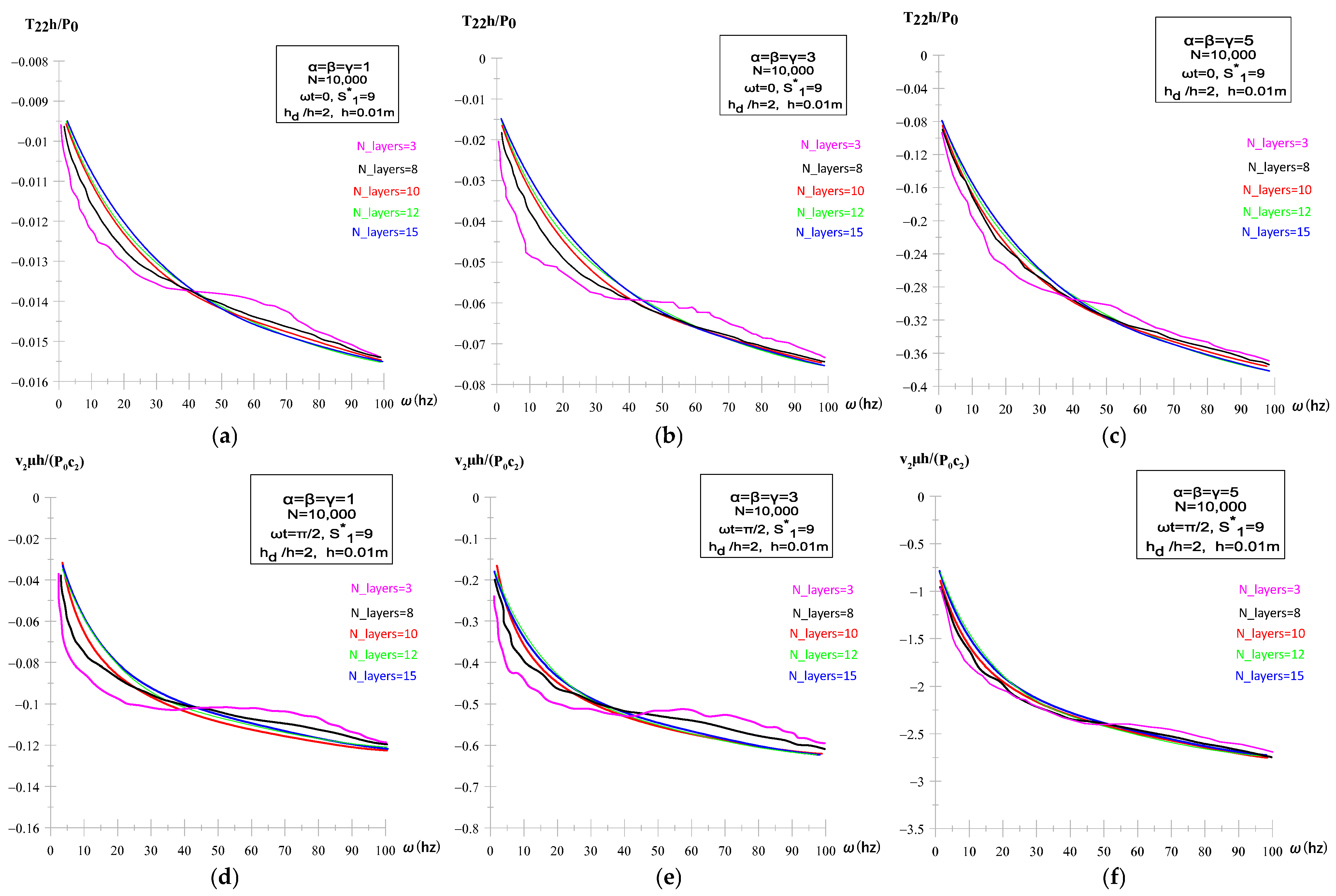
When calculating the integrals in (21), the infinite integration interval [0, ∞] is replaced by the finite interval [0, S 1 * ] and this finite interval is further subdivided into a certain N number of shorter intervals, which are used in the Gaussian integration algorithm. The values of the integrated expressions in (21) at the sample points are calculated by the solution procedure described above. All these procedures are performed automatically using the PC programs created by the authors in MATLAB. Consequently, we have three parameters, such as Ns (the number of sublayers), N (the number of subintervals into which the interval [0, S 1 * ] is divided), and the value of S 1 * , in relation to which we must check and ensure the convergence of the numerical results. The convergence with respect to each parameter is studied separately for the stress and velocity components in 3 cases of grading α , β , γ which are (1, 3, 5). The convergence behavior of the stress component T 22 h / P 0 with respect to Ns was studied by varying the number of discretized layers Ns (3, 8, 10, 12, 15) under N = 10,000 and S 1 * = 9, the asterisk (*) denotes that the parameter S1 is kept constant during the analysis. The results in Figure 3a–c for every α , β , γ = ( 1 , 3 , 5 ) show that for very few sublayers (Ns = 3), the computed stress exhibits visible oscillations and deviations, particularly near the fluid–plate interface, which indicates insufficient resolution of the smooth gradation profile.
As the number of layers is increased (N = 8, 10, 12), the curves approach each other, and beyond Ns = 12, the lines practically coincide with the Ns = 15 case with accuracy 10−6, confirming convergence and demonstrating that a sufficiently refined discretization leads to numerically stable and physically meaningful results. The behavior of the velocity v 2 μ h / P 0 c 2 shown in Figure 3d–f demonstrates a close relation to the convergence pattern of the stress field T 22 h / P 0 , confirming that the accurate capture of the stress field ensures a physically correct representation of the velocity field as well. On the other hand, the convergence is enhanced for the high values of α , β , γ , which indicates the positive effect of high grading on the convergence.
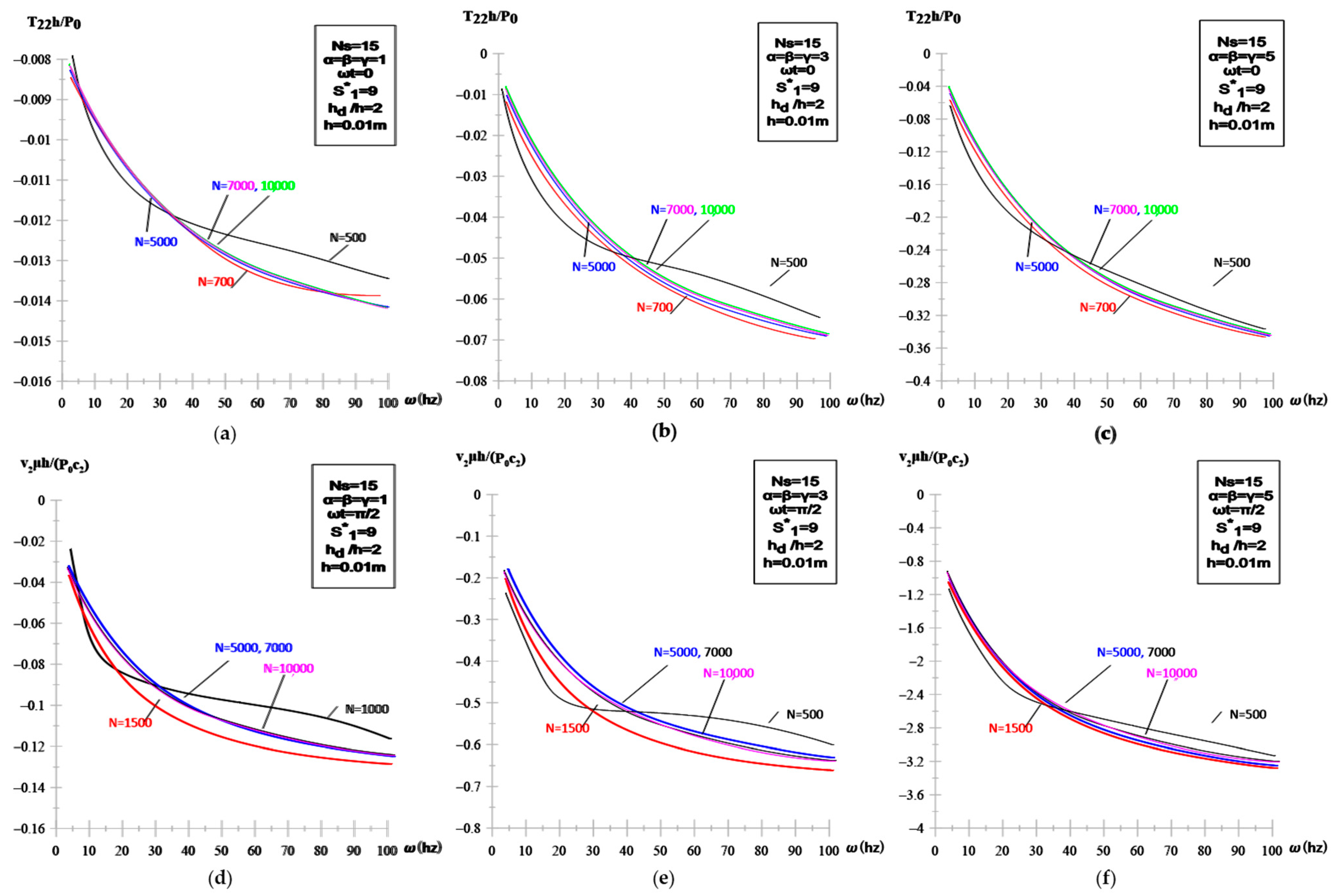
The convergence of the numerical results with respect to the number of the subintervals N is shown in Figure 4a–f for every α = β = γ = 1 , 3 , 5 under Ns = 15 and S 1 * = 9. The behavior of the stress component T 22 h / P 0 , exhibits a convergence pattern that is consistent with the velocity distribution v 2 μ h / P 0 c 2 . At lower discretization levels (N = 500, 1500), the curves deviate and show noticeable dispersion, indicating that insufficient resolution leads to inaccurate capture of the stress–fluid transfer across the interface. With refinement to N = 5000, the profiles begin to stabilize, and for N = 7000 and N = 10,000, the curves nearly coincide with accuracy 10−6, demonstrating that a sufficient number of spectral points is essential to achieve numerical convergence. Also, the figures show the clear positive effect of high grading on the convergence behavior.
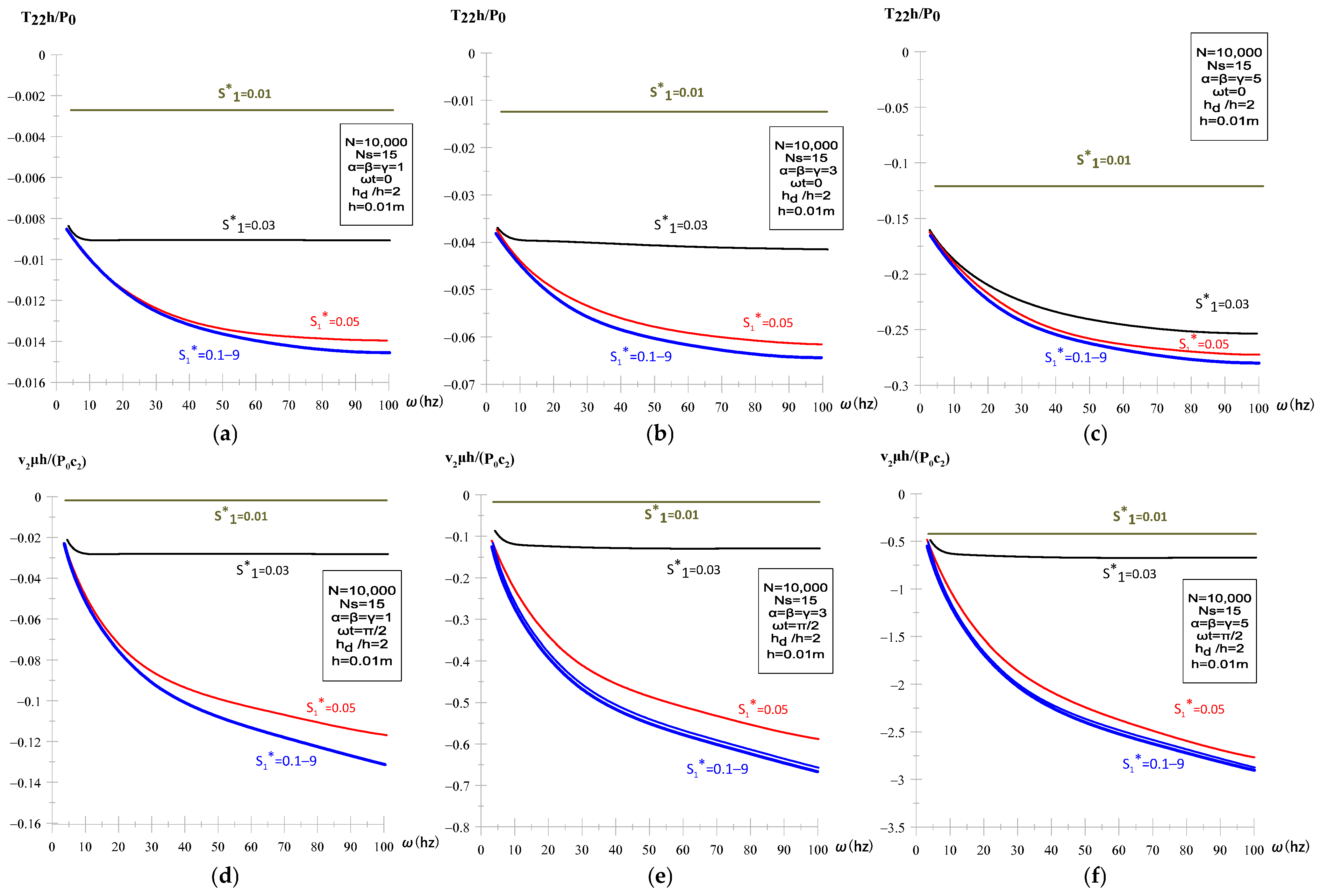
Depending on the integration interval parameter S 1 * , the results on the convergence of the numerical results are presented in (Figure 5a–c) demonstrate the convergence behavior of the normal stress component T 22 h / P 0 in the FGM plate. It is observed that for very small integration intervals ( S 1 * = 0.01, 0.03, 0.05), the calculated stress field exhibits visible oscillations and irregular deviations, particularly near the fluid–plate interface, which directly leads to overestimated amplitudes in the frequency response. With increasing values of S 1 * (from 0.1 up to 9), the results converge smoothly with accuracy 10−6, the lines of the frequency response curves practically coinciding for larger S 1 * , thereby confirming that the refinement of the integration interval enhances the stability and accuracy of the solution. The velocity distribution v 2 μ h / P 0 c 2 , shown in Figure 5d–f, exhibits a convergence pattern that is consistent with the behavior of the stress component T 22 h / P 0 .
Moreover, the variation of gradation indices systematically influences the stress T 22 h / P 0 and velocity v 2 μ h / P 0 c 2 , high gradation produces smoother profiles with reduced amplitudes and enhanced load-sharing capacity.
This concludes our consideration of the convergence of the numerical results in relation to the discretization parameters.

3.2. Effect of Fluid Depth Ratio and Plate Thickness

The numerical results presented in Figure 6a–c demonstrate the influence of two key geometrical parameters—namely the dimensionless fluid layer thickness ratio h d / h and the absolute plate thickness h—on the frequency-dependent behavior of the normal stress component at the fluid–FGM plate interface under static excitation conditions ω t = 0 . It is observed that the variation of h d / h in the range (0.2–5) produces systematic changes in the amplitude and distribution of the normal stresses. At small ratios ( h d / h = 0.2 ) , the stresses are markedly elevated, indicating the strong confinement of the fluid layer, which enhances the transmission of elastic disturbances from the plate to the fluid domain. As h d / h increases, the stress magnitudes reduce and the curves gradually stabilize. A similar moderating effect is revealed when the plate thickness is increased from h = 0.001 m to h = 0.1 m. Thin plates exhibit larger normal stresses, reflecting their reduced stiffness and higher susceptibility to fluid loading. In contrast, thicker plates redistribute stresses more evenly across the interface, thereby lowering peak amplitudes. This finding emphasizes that the accurate specification of plate thickness is crucial for capturing the stress–wave propagation and ensuring numerical convergence of the discrete analytical approach. At ω t = π / 2 , the hydroelastic response presented in (Figure 6d–f) demonstrates a consistent reduction in the magnitude of the normal stress component compared with the baseline case of ω t = 0 (Figure 6a–c).
Although the overall trends remain similar, with higher values of the fluid layer thickness ratio h d / h producing larger stress levels and increasing plate thickness (h) attenuating the stress response, the effect of the phase angle leads to noticeably smaller amplitudes. This attenuation reflects the diminished contribution of the hydrodynamic load in the quadrature condition, while the ordering of the curves for different h d / h values remains unchanged.
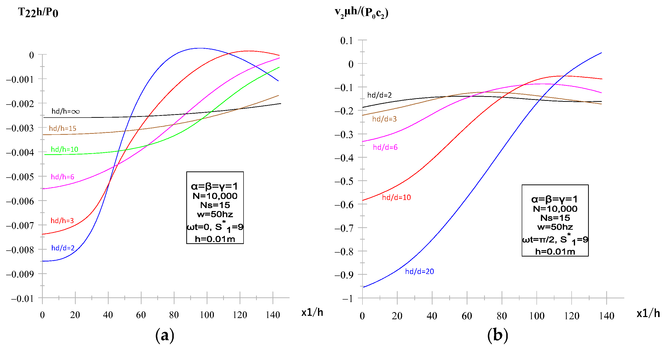
The numerical results obtained for the variation in the dimensionless fluid layer thickness ratio h d / h with values (2, 3, 6, 10, 15, and ) (Figure 7a,b) demonstrate that this parameter exerts a decisive influence on both the stress response T 22 h / P 0 and the velocity distribution v 2 μ h / P 0 c 2 along the dimensionless coordinate x 1 / h . As the fluid depth increases, the magnitude of the interfacial normal stress T 22 h / P 0 progressively decreases (in absolute value) and its distribution becomes smoother, indicating that for sufficiently large h d / h the finite-depth effect vanishes and the solution approaches the half-space case. A counterproductive behavior is observed in the velocity field: for shallow fluid layers ( h d / h = 2, 3) the velocity amplitudes decrease (in absolute value) and exhibit lower gradients across x 1 / h , while for deeper layers ( h d / h   10) the velocity curves have stringer gradients.
These findings emphasize that the depth ratio governs the balance between fluid inertia and structural stiffness in the coupled hydroelastic system and that accurate numerical representation of this parameter is essential to capture the correct damping and energy-transfer mechanisms in FGM structures. Therefore, the inclusion of various h d / h values not only enriches the reliability of the numerical scheme but also enhances the predictive capacity of the discrete analytical method for FGMs interacting with viscous fluids, which is in full consistency with the theoretical framework developed in Akbarov’s earlier investigations [26].
Now we try to explain why increasing the ratio h d / h leads to a decrease in interfacial stress and an increase in interfacial velocities. This is because increasing the ratio h d / h means increasing the distance between the rigid wall and the plate, and according to the obvious physico-mechanical considerations, increasing this distance leads to a decrease in the resistance of the fluid layer to the movement of the plate in the direction of the O x 2 axis. With this consideration, the above results on the influence of the ratio h d / h on the absolute values of the interfacial stress and the velocities can be explained. It follows from the foregoing results that the absolute values of the interfacial stress and the interfacial velocity increase with the oscillation frequency of the external force. This increase is consistent with known physical-mechanical considerations and in the daily observation of the relevant events. The change range 4   h z ω 600   h z of frequency selected under obtaining these results corresponds to the real daily frequencies observed in the modern construction elements of airplanes, high-speed cars and boats, etc. Moreover, in the previous related studies, the range of change of frequency is also selected as here. This explains the selection of the frequency change range of the vibration of the external time-harmonic force.

3.3. Influence of Gradation Index and Excitation Phase

The results presented in Figure 8a–c show that the variation of the gradation indices   α = β = γ = 1, 3, and 5 together with the change in plate thickness values h = 0.001, 0.01, and 0.1 m has a marked influence on the frequency response of the normal stress component at the interface under static excitation conditions ω t = 0 .
It is established that with increasing gradation indices, the amplitudes of the stress response decrease systematically, since the ceramic-rich portion of the FGM plate dominates the stiffness distribution and ensures a more uniform redistribution of stresses across the thickness. At the same time, increasing the plate thickness from very thin (h = 0.001) to relatively thick (h = 0.1) reduces the overall magnitude of the stresses. The combined effect of gradation and thickness is evident in the smoother and more stable profiles of the stress–frequency curves shown in the figures, where the cases of   α = β = γ = 5 and h = 0.1 m display the lowest values of stress amplitudes.

3.4. Effect of Gradation Direction and Metal Type

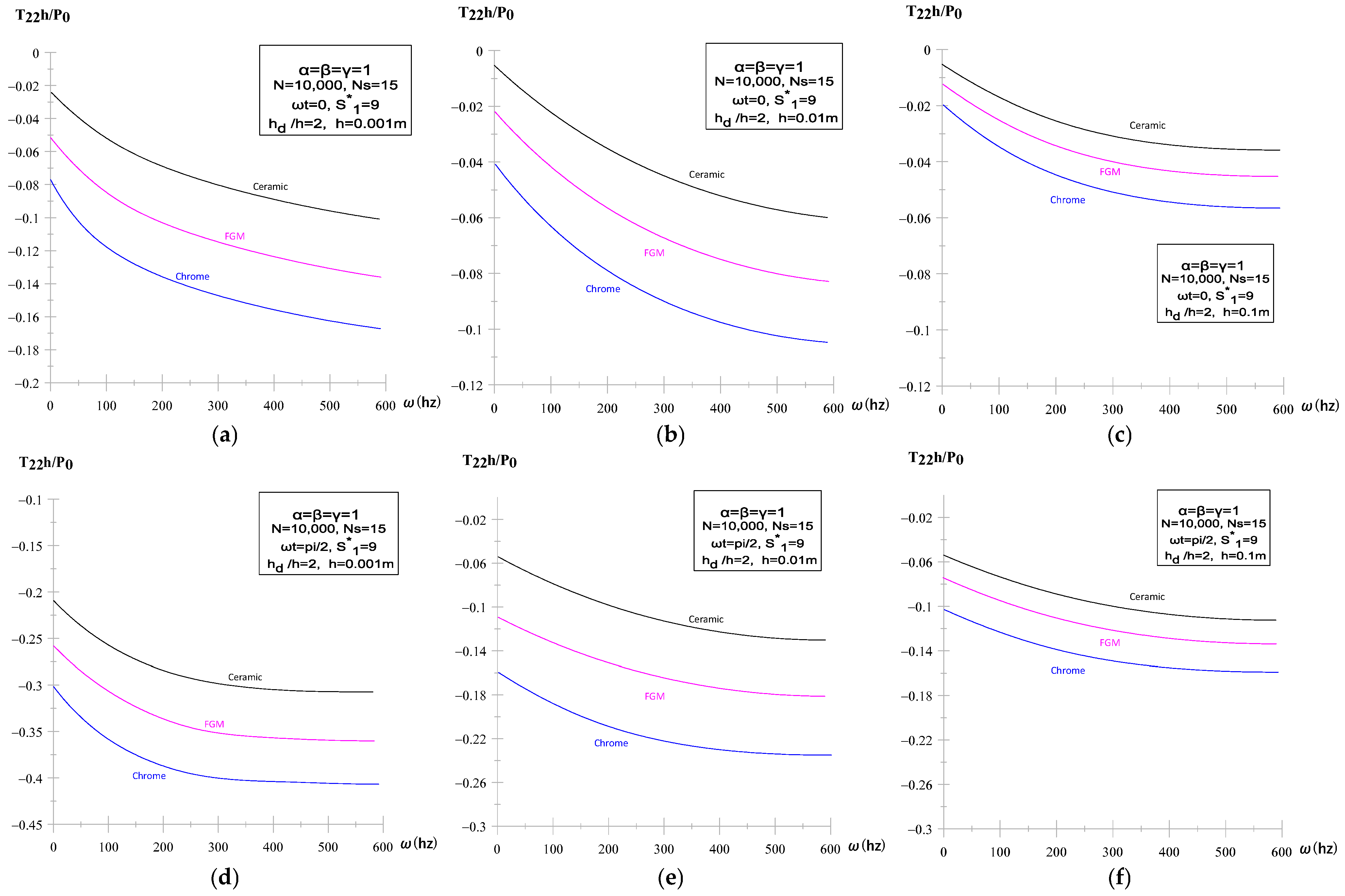
The obtained results (Figure 9a–c) show that the frequency response of the stress component T 22 h / P 0 is strongly governed by both the distribution of material properties across the thickness and the plate thickness parameter h. With increasing thickness (h = 0.1, 0.01, and 0.001 h), the overall magnitude of T 22 h / P 0 decreases for all plate types, indicating the stabilizing role of thicker configurations. Among the homogeneous cases, the chrome plate exhibits the smallest stress amplitudes, which is attributed to its higher stiffness and density, whereas the ceramic plate demonstrates the largest values, consistent with its brittle nature and reduced damping ability.
The FGM plate displays intermediate but more favorable behavior, where the smooth gradation of properties ensures moderate stress levels and avoids the sharp fluctuations observed in the homogeneous counterparts. Importantly, the response curves of the FGM plate also reveal a more gradual decay of stresses with thickness variation, which reflects its capacity to redistribute stresses and improve numerical convergence.
When the excitation phase is shifted to the out-of-phase condition ω t = π / 2 , the same general decrease in stress with increasing thickness is observed (Figure 9d–f), but the amplitude of T 22 h / P 0 is noticeably lower compared with the in-phase case.
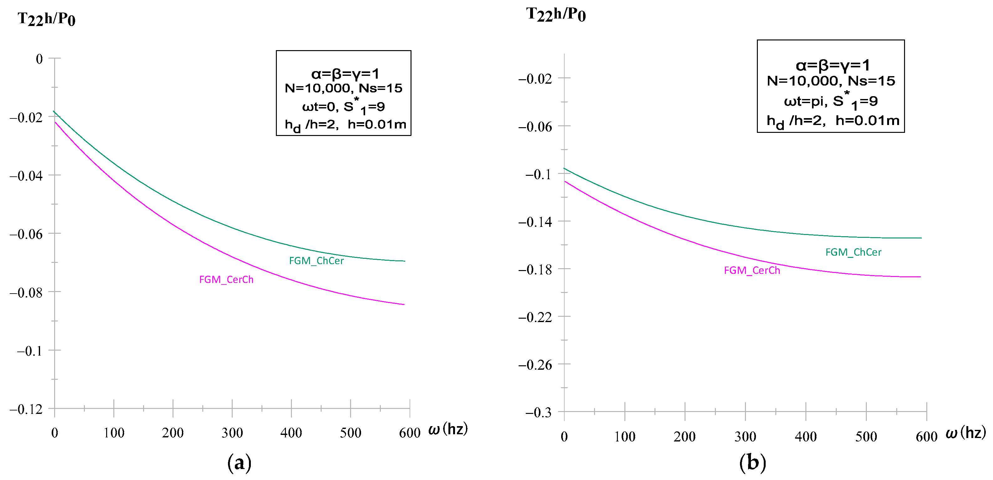
The frequency response of the stress component T 22 h / P 0 is strongly governed by the direction of material gradation through the plate thickness, as well as by the phase angle of the excitation. In Figure 10a, two gradation configurations were analyzed: ceramic-to-chrome (FGM cer–ch) and chrome-to-ceramic (FGM ch–cer). As presented in Figure 10, both arrangements exhibit a monotonically decreasing stress profile along the normalized thickness coordinate x 2 / h . The (FGM cer–ch) configuration consistently yields lower magnitudes, where the stiff, low-density ceramic-rich surface attenuates stress transfer more effectively than its inverse. In contrast, the (FGM ch–cer) ordering results in amplified stress levels due to the denser and more compliant chrome-rich surface, which promotes reflection within the plate.
Moreover, In Figure 10a,b, a clear influence of the excitation phase is observed: for ω t = 0 , the stress distributions are more uniform across the thickness, while at ω t = π / 2 the profiles reveal greater gradients and elevated values near the surfaces.
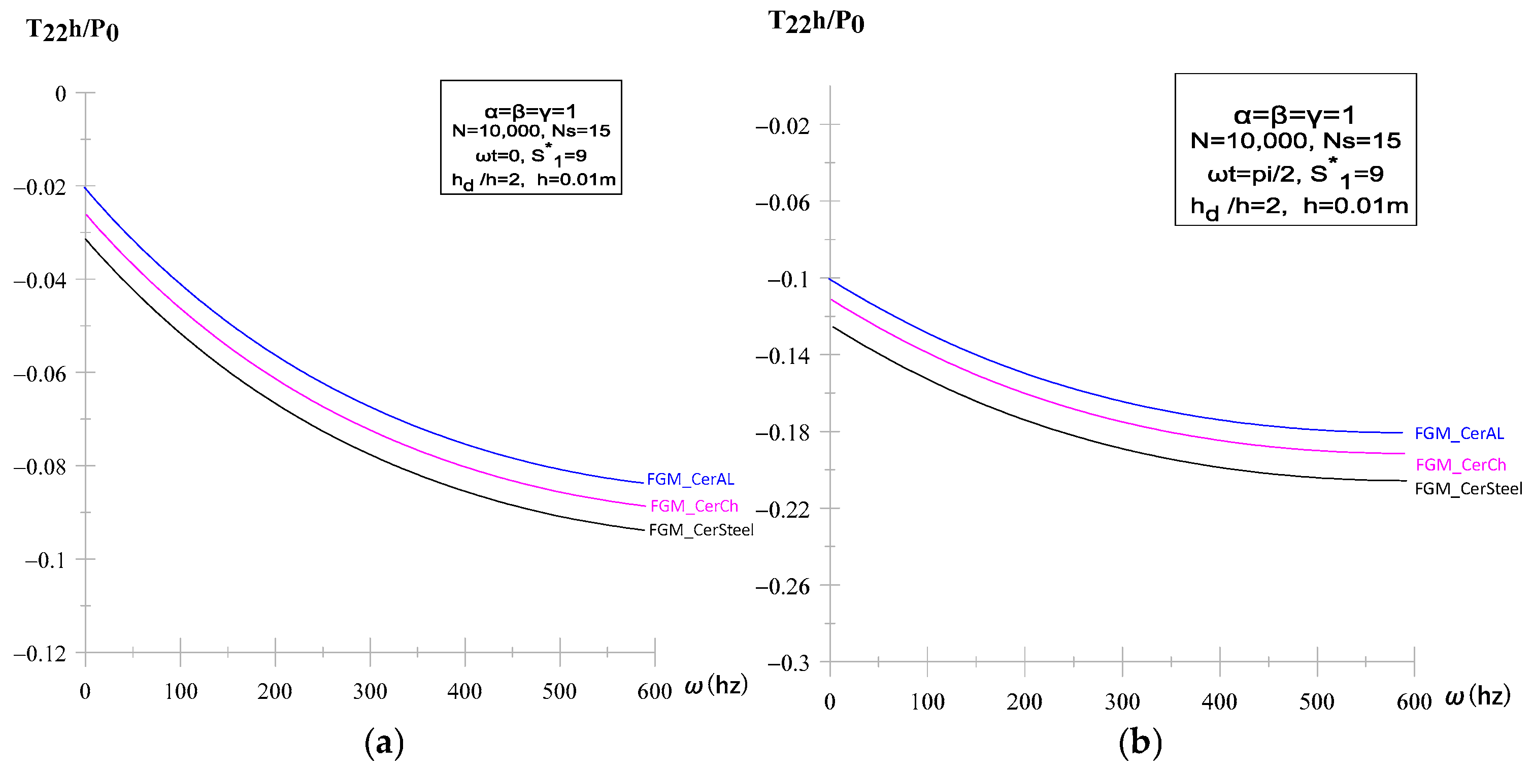
The investigation confirms the importance of testing different metallic counterparts when evaluating the frequency response of the interfacial stress T 22 h / P 0 in functionally graded ceramic–metal systems. By considering chrome, steel, and aluminum as the metallic phases, the results (Figure 11a) show that the variation in mechanical properties across the gradation strongly influences both the magnitude and distribution of stresses. Among the studied cases, ceramic–chrome exhibits the largest stress values due to the higher stiffness contrast, while ceramic–aluminum displays the lowest levels, reflecting the reduced modulus and density of the metallic phase. The ceramic–steel case lies between these two extremes, providing a balanced response. A further comparison of the frequency-dependent stress profiles at ω t = 0 and π / 2 illustrates in Figure 11b how the temporal phase alters the stress distribution: at ω t = 0 , the stresses are more concentrated and sensitive to the metal type, whereas at ω t = π / 2 the curves appear smoother with diminished amplitudes, indicating a redistribution of the load through the graded structure. These findings underline that both the selection of the metallic phase and the gradation orientation are critical parameters for enhancing the predictive capability of numerical analyses of FGMs, ensuring that the stress transfer across ceramic–metal interfaces is realistically represented under dynamic excitation.
As a further discussion, in the previous setup, the fluid-side face is ceramic-rich and the back face is metal-rich; therefore, the interfacial modulus is effectively E int E c and does not change when   α , β , γ (1,3,5) are varied—those coefficients shape the through-thickness profile E ( x 2 ) (steepness), not which phase is at the interface.
Consequently, the material–contrast ratio E c / E m acts as a pair property that changes only when we change the metal (Al, steel, chrome) or the ceramic. With the ceramic fixed, increasing metal stiffness raises Em and thus decreases E c / E m . In our results, however, stiffer metals still produce larger interfacial stresses (ceramic–Cr > ceramic–steel > ceramic–Al), indicating that the hydroelastic impedance (stiffness + density) dominates the interface response more strongly than the numerical value of E c / E m alone. When we reverse the gradation direction (metal at the interface), the interfacial material switches from ceramic to metal, and the response changes accordingly—confirming that the face material at the interface, not the distribution steepness, primarily sets the interfacial behavior. These material effects interact with geometric and dynamic factors. For example, larger fluid-depth ratios h d / h generally increase both stress and velocity magnitudes by enhancing inertial coupling, while the excitation phase ω t modulates these amplitudes through timing of peak pressure relative to structural displacement (with ω t = π / 2 consistently lowering stress magnitudes compared to ω t = 0 ). The combination of E c / E m , gradation direction, h d / h , and phase thus defines a multi-parameter design space for tailoring hydroelastic performance: E c / E m and gradation direction set the baseline interface stiffness, while h d / h and phase control how strongly the fluid can excite or damp that interface.

3.5. Summary of Main Numerical Findings

Table 2 summarizes the main parametric findings of this study. It highlights the relative influence of discretization choices, geometrical parameters, material gradation, and excitation phase on the hydroelastic response. The table provides a compact reference that complements the detailed figures, enabling clearer comparison between cases and enhancing the overall readability of the results.

4. Conclusions

This study has addressed the forced vibration behavior of hydroelastic systems comprising a functionally graded material (FGM) plate, a compressible viscous fluid, and a rigid wall, using a discrete analytical method. Compared with earlier investigations, which predominantly examined free or thermal vibrations of FGMs in incompressible or inviscid fluids, the present work extends the state of the art by incorporating both viscosity and compressibility effects under harmonic excitation within a confined fluid domain. To the best of our knowledge, no prior study has formulated and solved this combined problem for FGMs, thereby filling an important gap in the hydroelastic vibration literature.
The numerical results confirm and generalize earlier findings on homogeneous plates while revealing distinct features introduced by FGMs. In particular, the graded transition between ceramic and metallic phases improves stress redistribution compared to homogeneous materials, mitigating the sharp stress peaks observed in purely ceramic plates and offering enhanced damping compared to metallic ones. These outcomes are consistent with the broader trend in recent studies, which have shown the advantages of FGMs in vibration control, but the present work demonstrates their effectiveness in the more complex context of viscous–compressible fluid interactions with rigid-wall confinement.
From a methodological standpoint, the discrete analytical approach proved capable of accurately capturing the coupled plate–fluid dynamics across a wide frequency range, provided sufficient discretization is applied. This extends previous applications of the method to homogeneous or viscoelastic plates, showing its adaptability to FGM configurations.
Overall, this work contributes new knowledge by:
*
Extending forced vibration analysis to FGM plates in viscous, compressible, and confined fluid domains.
*
Demonstrating how gradation index, material type, and orientation systematically influence hydroelastic stresses and velocities.
*
Establishing the discrete analytical method as a reliable tool for analyzing complex FGM–fluid interactions.
These insights not only deepen the theoretical understanding of FGM-based hydroelastic systems but also provide practical guidance for designing marine, aerospace, and energy structures where vibration control in viscous and compressible fluid environments is critical.

Author Contributions

Conceptualization, M.M.A. and S.D.A.; methodology, M.M.A.; software, M.M.A.; validation, M.M.A. and S.D.A.; formal analysis, M.M.A.; investigation, M.M.A.; resources, M.M.A.; data curation, M.M.A.; writing—original draft preparation, M.M.A.; writing—review and editing, M.M.A. and S.D.A.; visualization, M.M.A.; supervision, S.D.A.; project administration, S.D.A. All authors have read and agreed to the published version of the manuscript.

Funding

This research received no external funding.

Institutional Review Board Statement

Not applicable.

Informed Consent Statement

Not applicable.

Data Availability Statement

Data available on request from the corresponding author.

Acknowledgments

The authors would like to thank Yildiz Technical University.

Conflicts of Interest

The authors declare no conflicts of interest.

References

  1. Lamb, H. Axisymmetric vibration of circular plates in contact with water. Proc. R. Soc. Lond. A 1921, 98, 205–216. [Google Scholar]
  2. Fu, Y.; Price, W.G. Interactions between a partially or totally immersed vibrating cantilever plate and surrounding fluid. J. Sound. Vib. 1987, 118, 495–513. [Google Scholar] [CrossRef]
  3. Bagno, A.M.; Guz, A.N.; Shchuruk, G.I. Influence of fluid viscosity on waves in an initially deformed compressible elastic layer interacting with a fluid medium. Int. Appl. Mech. 1994, 30, 643–649. [Google Scholar] [CrossRef]
  4. Bagno, A.M.; Guz, A.N. Elastic waves in prestressed bodies interacting with fluid (Survey). Int. Appl. Mech. 1997, 33, 435–465. [Google Scholar] [CrossRef]
  5. Amabili, M. Effect of finite fluid depth on the hydroelastic vibrations of circular and annular plates. J. Sound. Vib. 1996, 191, 909–925. [Google Scholar] [CrossRef]
  6. Jeong, K.-H.; Kim, K.-J. Hydroelastic vibration of a circular plate submerged in a bounded compressible fluid. J. Sound. Vib. 2005, 283, 153–172. [Google Scholar] [CrossRef]
  7. Chapman, C.J.; Sorokin, S.V. The forced vibration of an elastic plate under significant fluid loading. J. Sound. Vib. 2005, 281, 719–741. [Google Scholar] [CrossRef]
  8. Graham, W.R. Analytical approximations for the modal acoustic impedances of simply supported rectangular plates. J. Acoust. Soc. Am. 2007, 122, 719–730. [Google Scholar] [CrossRef]
  9. Atkinson, C.; de Lara, M.M. The frequency response of a rectangular cantilever plate vibrating in a viscous fluid. J. Sound. Vib. 2007, 300, 352–367. [Google Scholar] [CrossRef]
  10. Ayela, C.; Nicu, L. Micromachined piezoelectric membranes with high nominal quality factors in Newtonian liquid: A Lamb’s model validation at the microscale. Sens. Actuators A Phys. 2007, 123, 860–868. [Google Scholar] [CrossRef]
  11. Kozlovsky, Y. Vibration of plates in contact with viscous fluid: Extension of Lamb’s model. J. Sound. Vib. 2009, 326, 332–339. [Google Scholar] [CrossRef]
  12. Askari, M.; Ghaffarzadeh, H.; Ghannad, M. Hydroelastic vibration of circular plates in contact with fluid. Appl. Math. Model. 2013, 37, 2574–2587. [Google Scholar]
  13. Khorshidi, K.; Malekzadeh, P. Hydroelastic vibration of functionally graded rectangular plates in fluid domains. Compos. Struct. 2015, 127, 74–83. [Google Scholar]
  14. Canales, F.; Ritto, T.G.; Rochinha, F.A. On the hydroelastic response of elastic plates in compressible fluid domains. J. Fluids Struct. 2018, 81, 160–173. [Google Scholar]
  15. Li, Y.; Liu, B.; Li, X. Free vibration of FGM Mindlin plates partially submerged in incompressible fluid. Thin-Walled Struct. 2022, 178, 109420. [Google Scholar]
  16. Ardıç, H.; Güler, M.A. Hydroelastic vibration analysis of FGM Mindlin plates in viscous fluids via isogeometric methods. Ocean. Eng. 2025, 290, 120955. [Google Scholar]
  17. Akbarov, S.D.; Ismailov, M.I.; Kepceoğlu, A. Forced vibration of a pre-stressed elastic plate interacting with compressible viscous fluid in rigid-wall confinement. Mech. Adv. Mater. Struct. 2017, 24, 1–15. [Google Scholar]
  18. Farsani, R.E.; Malekzadeh, P.; Alibeigloo, A. Free vibration analysis of porous functionally graded plates in contact with fluid. Ocean. Eng. 2021, 232, 109120. [Google Scholar] [CrossRef]
  19. Farsani, R.E.; Malekzadeh, P.; Alibeigloo, A. Hydroelastic analysis of variable-thickness porous FGM plates in fluid tanks. Appl. Math. Model. 2022, 103, 556–573. [Google Scholar]
  20. Pham, T.; Do, T.; Bui, T. Thermal vibration of multidirectional porous FGM plates interacting with fluid. Eur. J. Mech. A Solids 2024, 103, 105183. [Google Scholar]
  21. Murari, R.; Kumar, V.; Sharma, R. Vortex-induced vibrations of functionally graded auxetic plates in fluid environments. Compos. Part. B Eng. 2024, 266, 112012. [Google Scholar]
  22. Kurpa, L.; Drach, I.; Tserkovnyuk, O. Free vibration analysis of porous FGM plates using the R-functions method. Compos. Struct. 2024, 317, 117276. [Google Scholar]
  23. Norouzi, A.; Ghadiri, M.; Asemi, K. Fluid–structure interaction in nonlinear plates under flow: A review. Arch. Appl. Mech. 2023, 93, 1461–1483. [Google Scholar]
  24. Birman, V.; Byrd, L.W. Modeling and analysis of functionally graded materials and structures. Appl. Mech. Rev. 2019, 62, 1–25. [Google Scholar]
  25. Guz, A.N. Dynamics of Compressible Viscous Fluid; Cambridge Scientific Publishers: Cambridge, UK, 2009. [Google Scholar]
  26. Akbarov, S.D.; Ismailov, M.I. The forced vibration of the system consisting of an elastic plate, compressible viscous fluid and rigid wall. J. Vib. Control 2015, 23, 1809–1827. [Google Scholar] [CrossRef]
  27. Guz, A.N. Elastic Waves in Bodies with Initial (Residual) Stresses; A.C.K.: Kiev, Ukraine, 2004. [Google Scholar]
  28. Cao, X.; Jin, F.; Jeon, I. Calculation of propagation properties of Lamb waves in a functionally graded material (FGM) plate by power series technique. NDT E Int. 2011, 44, 84–92. [Google Scholar] [CrossRef]
  29. Kuzeci, Z.E.; Akbarov, S.D. Vibration of a Two-Layer “Metal+PZT” Plate Contacting with Viscous Fluid. Comput. Mater. Contin. 2023, 74, 4341–4350. [Google Scholar] [CrossRef]
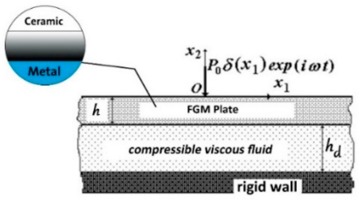
Figure 1. Representation of an FGM plate with forced vibration.
Applsci 15 10854 g001
Figure 2. Illustration for plate sublayers discretization.
Applsci 15 10854 g002
Figure 3. Convergence of the numerical results related to the stress and velocity with respect to the number of layers Ns in the case where   α = β = γ = 1 (a,d), 3 (b,e) and 5 (c,f).
Applsci 15 10854 g003
Figure 4. Convergence of the numerical results related to the stress and velocity with respect to the number of N in the case where   α = β = γ = 1 (a,d), 3 (b,e) and 5 (c,f).
Applsci 15 10854 g004
Figure 5. Convergence of numerical results related to the stress and velocity, with respect to S 1 * in the case where α = β = γ = 1 (a,d), 3 (b,e) and 5 (c,f).
Applsci 15 10854 g005
Figure 6. The frequency response of stress depends on the value of ( h d / h ) and the thickness of the plate (h) = (0.001 m) (a,d), (0.01 m) (b,e) and (0.1 m) (c,f), where ω t = 0 and π / 2 .
Applsci 15 10854 g006
Figure 7. Distribution of the stress (a) and the velocities (b) with respect to the dimensionless coordinate x 1 / h under different values of h d / h .
Applsci 15 10854 g007
Figure 8. The frequency response of stress depends on the value of   α = β = γ and the thickness of the plate (h) = (0.001 m) (a,d), (0.01 m) (b,e) and (0.1 m) (c,f), where ω t = 0 and π / 2 .
Applsci 15 10854 g008
Figure 9. Frequency response of numerical results related to the stress, obtained for the chrome, ceramic and FGM plates at values thickness of the plate (h) = (0.001 m) (a,d), (0.01 m) (b,e), and (0.1 m) (c,f), where ω t = 0 and π / 2 .
Applsci 15 10854 g009
Figure 10. Frequency response of numerical results related to the stress, obtained for the direction of material gradation (ceramic–chrome) and (chrome–ceramic) of the FGM plate where ( ω t = 0 ) (a) and ( ω t = π / 2 ) (b).
Applsci 15 10854 g010
Figure 11. Frequency response of numerical results related to the stress, obtained for the (ceramic–chrome), (ceramic–steel) and (ceramic–aluminum) of the FGM plate, where ( ω t = 0 ) (a) and ( ω t = π / 2 ) (b).
Applsci 15 10854 g011
Table 1. Mechanical properties of the plate materials and fluid parameters used in the analysis.
Material/Fluid Shear   Modulus   μ (GPa) Lamé Constant   λ (GPa) Density
ρ (kg/m3)
Young s   Modulus   E (GPa) Poisson’s Ratio ν Dynamic
Viscosity   μ ( 1 ) (kg/m.s)
Reference Density
ρ ( 1 ) (kg/m3)
Sound Speed
a 0 (m/s)
Plate(Cr)102.574.27190248.5 0.21
Ceramic118.11383900300 0.27
Fluid (Glycerin) 1.39312601927
Table 2. Summarizes the main parametric findings of this study.
Parameter StudiedRange/Cases Main   Effect   on   Stresses   T 22 h / P 0 Main   Effect   on   Velocities   v 2 μ h / P 0 c 2 Notes
Number of sublayers Ns3–15Converges after Ns ≥ 12Converges with stress resultsLow Ns gives oscillations
Intervals N500–10,000Stable for N ≥ 7000Same trendSpectral resolution critical
Integration parameter S 1 * 0.01–9Stable for S 1 * ≥ 0.1Matches stress convergenceSmall β causes oscillations
Fluid depth ratio h d / h 0.2–15 h d / h → ↓ stresses h d / h → ↑ velocitiesShallow fluid amplifies stresses
Plate thickness (h)0.001–0.1 mThin → ↑ stressesThin → ↑ velocitiesThick plates give more stabilization
Gradation index   α = β = γ 1, 3, 5Higher n → ↓ stressesHigher n → smoother profilesCeramic-rich improves stiffness
Gradation directionCer→Metal vs. Metal→CerCer→Metal → ↓ stressesMetal at interface → ↑ stressesInterface material dominates
Metallic phaseCr, Steel, AlCr > Steel > Al (stress level)Same orderingDue to stiffness + density
Excitation phase φ 0 vs. π / 2 φ = π / 2 → ↓ amplitudes φ = π / 2 → smoother velocityPhase shifts damp interaction
The arrow indicates the direction of the increasing parameter values.
Disclaimer/Publisher’s Note: The statements, opinions and data contained in all publications are solely those of the individual author(s) and contributor(s) and not of MDPI and/or the editor(s). MDPI and/or the editor(s) disclaim responsibility for any injury to people or property resulting from any ideas, methods, instructions or products referred to in the content.