Abstract
The Anti-roll Bar is a critical component of the automobile suspension system. The stiffness of the Anti-roll Bar significantly impacts the suspension stiffness and is related to the interference of the rubber bushing. To obtain reasonable Anti-roll Bar stiffness and determine the appropriate amount of rubber bushing interference, a certain type of automotive lateral Anti-roll Bar model was established through ANSYS Workbench finite element analysis for the rubber bushing material using a Mooney–Rivlin two-parameter model simulation. A different amount of interference was set up between the rubber bushing and the various parts of the bushing. The overload simulation was performed to simulate the bushing in an overload state with a different amount of interference between the rubber bushing and the various parts of the bushing. The stresses of the three main parts of the Anti-roll Bar (the clamp, skeleton, and bushing) were analyzed in an overload state. The radial and torsional stiffness values of the Anti-roll Bar are analyzed under the interference state. The influence of interference fit variations in different mating parts on the radial and torsional stiffness of the Anti-roll Bar is studied. It is determined that the stiffness value of the Anti-roll Bar meets the requirements when the interference fit between the bushing and rod is 1 mm, the bushing-plate interference is 2 mm, and the interference fit between the bushing and clamp is 0.6 mm, provided that the strength requirements of each part are met. This study provides important reference significance for designing.
1. Introduction
The Anti-roll Bar is a crucial safety component that counteracts the vehicle’s roll (lateral inclination) during turns. Which increases low-speed agility and improves high-speed stability [1]. The stiffness of the Anti-roll Bar (radial and torsional stiffness) is an important factor affecting the stability of automobile driving, which has a great influence on the vehicle’s lateral sway performance [2]. Rubber bushings are a crucial component of Anti-roll Bars, offering the advantage of enhancing vehicle stability and shock absorption performance [3].
Nie Zhenxue investigated the relationship between the dimensions of the components and static stiffness of rubber bushings for automotive shock absorbers [4]. Lv Zhicheng analyzed the stiffness of stabilizer bar bushing by Abaqus(6.11) finite element analysis software to get the bushing design that meets the usage requirements [5]. Yogesh Kumar and Mohamed Hassan studied the impact of Anti-roll Bars on vehicle handling and ride comfort [6,7]. Pan Haijie in order to evaluate the structural rationality of the Anti-roll Bar, established a certain type of stabilizer bar 1/2 finite element model and analyzed the torsional stiffness of the stabilizer bar under load [8]. M. Cerit and K. Junik investigated the effect of rubber hardness on Anti-roll Bar fatigue and mechanical properties [3,9]. Brown A et al. investigated the effect of interference fits on component fatigue life [10,11,12,13,14,15]. Anyang W et al. examined the impact of interference fits on component strength [16,17,18]. Elvio B et al. studied methods for obtaining interference fits between parts and determined the magnitude of sliding torque for different interference fits to establish the minimum interference required to meet specifications [19,20,21]. However, none of them analyzed the Anti-roll Bar stiffness when the rubber bushing was in an overfilled state.
The amount of interference between the rubber bushing and other parts can significantly affect the Anti-roll Bar stiffness. Low radial stiffness can lead to unintended bending of the stabilizer bar under complex conditions, affecting the anti-roll effect, but too high radial stiffness may increase local stresses and reduce service life. High torsional stiffness makes the vehicle handling more precise and the sway suppression is strong, but it may reduce the independence of unilateral wheels against bumps and affect the comfort, while low torsional stiffness can improve the comfort, but the turning sway is obvious and the handling limit is reduced. Therefore, it is important to study the effect of bushing interference on the stiffness of the Anti-roll Bar, which is of great significance for improving vehicle comfort and strengthening vehicle handling capability.
To obtain the stiffness value of the anti-roll bar under interference preload conditions and investigate the effect of interference variation on its stiffness, the interference magnitudes between the rubber bushings and various components were determined to ensure compliance with the anti-roll bar stiffness requirements. A finite element model was established using ANSYS Workbench (2022) software based on the interference conditions among the clamp, base plate, rod, and rubber bushing. The Mooney–Rivlin two-parameter model was employed to simulate the rubber material, while constraints, boundary conditions, and loads were applied to the model according to actual working conditions. Displacement and rotational loads consistent with experimental conditions were applied to the rod to obtain the bushing force–displacement and torque–rotation angle curves, enabling calculation of the lateral stabilizer bar’s radial and torsional stiffness. Stress analysis was conducted on the clamp, plastic skeleton, and rubber bushing while the bushing was in an interference fit state. The study investigated the influence of interference variation at each mating interface on the stabilizer bar’s stiffness, providing valuable references for subsequent rubber bushing design.
2. Materials and Methodology
2.1. CAD Model of Anti-Roll Bar
SolidWorks(2016) is used to create a 3D model of an Anti-roll Bar. The Anti-roll Bar mainly consists of five parts: clamp, rubber bushing, skeleton, rod and base plate. The assembly relationship is shown in Figure 1. The rubber bushing has interference with the rod, the clamp, and the base plate. In this paper, the interference between the bushing and rod is the radius interference value. The size of the interference is determined by the geometric position of the rubber bushing and the parts modeled in the geometric model. The range of variation in the interference amount is set according to the parameter requirements of a factory, and the interference part of the bushing is shown in Figure 2. The range of variation is shown in Table 1. The lower limits of the interference fits for these three interfaces are designed to ensure sufficient static friction between the bushing and the components, preventing relative slippage and noise under torque. The upper limits are constrained by the maximum allowable installation strain of the rubber material and assembly feasibility, thereby avoiding permanent damage to the rubber during the press-fit process.
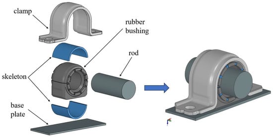
Figure 1.
Schematic diagram of Anti-roll Bar assembly.
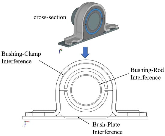
Figure 2.
Schematic diagram of Anti-roll Bar bushing interference.

Table 1.
Variable range of interference for each fit.
2.2. Model Meshing
The 3D model of the anti-roll bar was simplified and meshed in Hypermesh. The number and size of mesh elements directly impact the efficiency and accuracy of the final solution, making mesh generation critical. To overcome volume locking phenomena in finite element simulations of rubber materials, the C3D8R element type was employed. For computational efficiency, the rubber bushing, clamp, and skeleton were meshed with a 1 mm element size, while other components used a 2 and 3 mm-mesh size. The resulting mesh, shown in Figure 3, comprised 172,585 elements and 138,005 nodes.
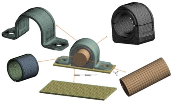
Figure 3.
Mesh division of Anti-roll Bar components.
2.3. Material Parameters
The rubber material used for the rubber bushing in the Anti-roll Bar is characterized by hyperelasticity, volume incompressibility and large deformation, which can generate large strains and show obvious nonlinear characteristics. This nonlinear characteristic leads to the complexity of its intrinsic relationship. Therefore, it cannot be treated like general metal materials, for which only a few coefficients are sufficient to describe the material properties. It is generally assumed that rubber materials are isotropic and incompressible superelastomers, which are mainly described by the strain energy function of the rubber material constitutive model. In this paper, the Mooney–Rivlin strain energy function is used [22], which is commonly used in finite element simulation, to construct the intrinsic model of rubber material, and its strain energy function expression is [23]:
where is the strain potential energy, and are the first and second Green strain invariants, represents the principal stretches, and and are the Mooney–Rivlin constants.
When the hardness of the rubber material is known, the Mooney–Rivlin constants , can be calculated from empirical equations and [22].
The hardness of the rubber bushing ranges from 50–65 SHA, and the values of and of the rubber material are calculated from Equations (4) and (5) as shown in Table 2.

Table 2.
Values of , at different hardnesses.
The material of clamp, rod and base plate in the Anti-roll Bar assembly is structural steel, and the yield stress is 400 MPa. The plastic skeleton material is PA66/GF30 (Shanghai Pret Composite Materials Co., Ltd. Shanghai, China), and the breaking stress is 160 MPa. The rubber parameter is selected as the material parameter when the hardness is 60 SHA, and the tensile strength is 20 MPa, and the specific material parameter is shown in Table 3.

Table 3.
Material parameters.
2.4. Boundary Condition
The contact relationship between the clamp and bushing, as well as between the base plate and bushing, is set as friction contact with a friction coefficient of 0.2. The friction coefficient between the rod and bushing is set to 0.5. Binding contact is established between the skeleton and bushing, and between the clamp and base plate. Simultaneously, the friction coefficient is set to 0.1 for the self-contacting portion of the rubber bushing. A fixed constraint is applied to the bottom surface of the base plate. A single analysis step is configured and an interference simulation is performed using the contact relationships set up in Workbench.
2.5. Model Nonlinear Verification
Rubber materials exhibit hyperelastic characteristics. To verify that the Mooney–Rivlin two-parameter model can capture the nonlinear behavior of rubber, the material parameters mentioned earlier were used to simulate the loading and unloading of a rubber bushing under 1 mm displacement. The resulting force–displacement curve is shown in Figure 4. Both the loading and unloading stages display significant nonlinearity. Moreover, the loading and unloading paths do not coincide, indicating a hysteresis effect. Therefore, the Mooney–Rivlin two-parameter model is capable of capturing the nonlinear behavior of rubber.
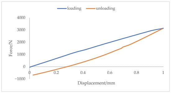
Figure 4.
Bushing Force–displacement Curve.
3. Results and Discussion
3.1. Stiffness Change Coefficient
In order to analyze the relationship between the radial stiffness and torsional stiffness of the Anti-roll Bar and the change in the interference of each mating part, the ratio of the rate of change in the Anti-roll Bar stiffness to the rate of change in the interference of the mating part is defined as the coefficient of change in the stiffness, which is shown in Equation (6) [4].
where is the stiffness change coefficient, is the stiffness value after the change in bushing overload; is the stiffness value at the initial overload; is the size of the bushing overload after the change in bushing overload; and is the bushing overload at the initial state. When is positive, it means that the stabilizer bar stiffness and the change in the excess amount are positively proportional, that is, the increase in the excess amount corresponds to the increase in the stabilizer bar stiffness. When is negative, it means that the stabilizer bar stiffness and the change in the excess amount are inversely proportional, that is, the increase in the excess amount corresponds to the decrease in the stabilizer bar stiffness.
3.2. Overfilling Simulation Results
Figure 5 shows the maximum interference values at three mating locations: 1 mm interference between the bushing and rod, 2 mm interference between the bushing and plate, and 0.6 mm interference between the bushing and clamp. Workbench static analysis calculates the stresses in the bushing, skeleton, and clamp under these interference conditions. The maximum stress of the clamp is 243.2 MPa, which is located at the far corner of the outer surface of the clamp, and is less than the material yield limit of 400 MPa. The maximum stress of the rubber bushing is located at the tip of the chamfered hole of the bushing, and is 7.9 MPa, which is less than the tensile strength of the rubber of 20 MPa. The upper and lower two halves of the plastic skeleton have the same distribution of the stress. The maximum stress is located at the top surface of the inner arch of the skeleton, which is 77.3 MPa, smaller than the fracture stress of 160 MPa.
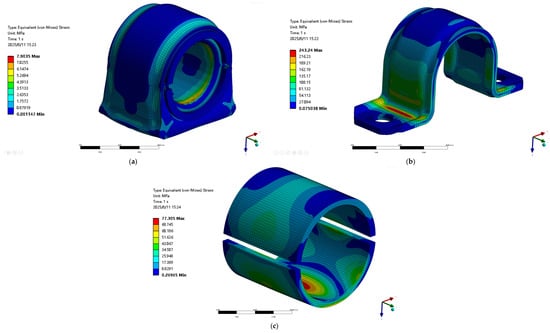
Figure 5.
Stress cloud map of important components under interference fit conditions; (a) Rubber bushing stress, (b) Clamp stress, (c) Skeleton stress.
3.3. Loading Settings
A second analysis step is set up based on the Anti-roll Bar overloaded state, in which a load is applied to the bar. The radial stiffness of the stabilizer bar is determined by applying a Z-direction displacement of +0.6 mm to the bar and measuring the resulting support reaction force. The torsional stiffness of the Anti-roll Bar is determined from the reaction moment that results from applying a torsion angle of +15° about the Y-axis. During each calculation, the interference fit of one component is incrementally increased while the interference fits of the other two components remain unchanged, thereby obtaining stiffness values under different interference conditions.
3.4. Effect of Interference Fit Between the Bushing and Rod on Stiffness
While the interference fits between the bushing and base plate (2 mm) and between the bushing and clamp (0.6 mm) were held constant, the interference between the bushing and rod was gradually increased to 0.3, 0.5, 0.7, and 1.0 mm. The resulting radial and torsional stiffness values of the Anti-roll Bar for these different interference conditions are shown in Figure 6.
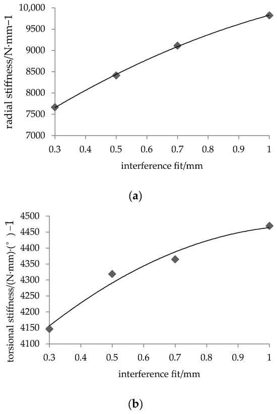
Figure 6.
Stiffness and Interference fit between the bushing and rod variation relationship curve; (a) Relationship between radial stiffness and changes in bushing and rod interference fit, (b) Relationship between torsional stiffness and changes in bushing and rod interference fit.
Figure 6 shows the relationship between the Anti-roll Bar stiffness and the interference fit at the bushing and rod interface. Both the radial and torsional stiffness increase nonlinearly with the interference fit. The increase in interference from 0.3 mm to 1 mm results in a 28.1% increase in radial stiffness and a 7.9% increase in torsional stiffness.
is defined as 0.3 mm, and is the stiffness value at this interference level. The stiffness variation coefficient for both radial and torsional stiffness can then be obtained using Equation (6). Figure 7 shows the relationship between this coefficient and the change in interference at the bushing and rod interface.
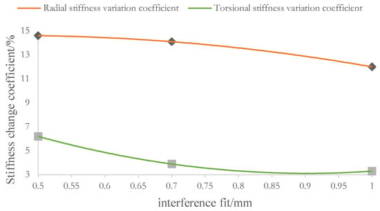
Figure 7.
Stiffness change coefficient and Interference fit between the bushing and rod change relationship diagram.
- 1.
- The relationship between stiffness and interference are all positive, as shown in Figure 7. This demonstrates that the stabilizer bar’s radial and torsional stiffness are proportional to the change in bushing and rod interference, with stiffness increasing as interference increases.
- 2.
- The coefficient of variation for radial stiffness is larger than that for torsional stiffness. This indicates that radial stiffness is more sensitive to changes in the bushing and rod interference fit than torsional stiffness. Consequently, a change in interference produces a more significant variation in radial stiffness than in torsional stiffness.
- 3.
- When the interference gradually increases to 1 mm, the coefficient of variation for radial stiffness decreases from 14.6% to 12.0%, and that for torsional stiffness decreases from 6.2% to 3.3%. This indicates that the sensitivity of the Anti-roll Bar’s stiffness to changes in bushing and rod interference diminishes as the interference increases.
3.5. Effect of Interference Fit Between the Bushing and Base Plate on Stiffness
While the interference at the bushing and rod interface was held constant at 1 mm and at the bushing and clamp interface at 0.6 mm, the interference at the bushing and base plate interface gradually increased to 0.5, 1.0, 1.5, and 2.0 mm. The radial and torsional stiffness of the Anti-roll Bar, calculated after changing the interference at the bushing and base plate interface, is shown in Figure 8.
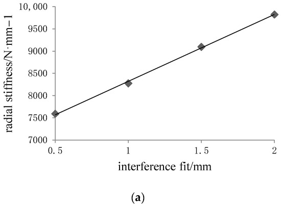
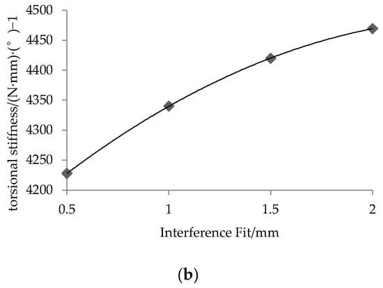
Figure 8.
Stiffness and Interference fit between the bushing and base plate variation relationship curve; (a) Relationship between radial stiffness and interference fit between bushing and base plate, (b) Relationship between torsional stiffness and interference fit between bushing and base plate.
Figure 8 shows the relationship between Anti-roll Bar stiffness and the change in interference at the bushing and base plate interface. Both the radial and torsional stiffness increase with the interference. The radial stiffness exhibits a linear increase, while the torsional stiffness follows a nonlinear trend. An increase in interference from 0.5 mm to 2.0 mm results in a 29.4% increase in radial stiffness and a 5.7% increase in torsional stiffness.
Similarly, the stiffness variation coefficient was calculated. Here, is defined as 0.5 mm, and is the corresponding stiffness value at this interference level. The relationship between this coefficient and the change in bushing and base plate interference is shown in Figure 9.
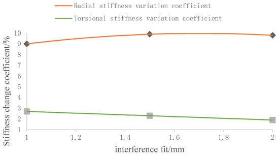
Figure 9.
Relationship between stiffness variation coefficient and Interference fit between the bushing and base plate variation.
- As can be seen from Figure 9, the stiffness variation coefficients of the Anti-roll Bar are all positive, indicating that both the radial stiffness and torsional stiffness are proportional to the change in bushing and base plate interference, and that the stiffness of the Anti-roll Bar increases with the interference.
- The coefficient of variation for radial stiffness is larger than that for torsional stiffness. This indicates that radial stiffness is more sensitive to changes in the bushing and rod interference fit than torsional stiffness. Consequently, a change in this interference produces a more significant variation in radial stiffness than in torsional stiffness.
- The stiffness variation coefficient in this case is smaller than that when altering the bushing and rod interference fit. The maximum radial stiffness variation coefficient when changing the bushing and rod interference fit is 14.6%, while the maximum radial stiffness variation coefficient when changing the bushing and base plate interference fit is 9.9%. The maximum torsional stiffness variation coefficient when altering the bushing and rod interference fit is 6.2%, whereas the maximum torsional stiffness variation coefficient when altering the bushing and base plate interference fit is 2.7%. That is, changes in the bushing and rod interference fit exert a greater influence on the Anti-roll Bar stiffness than changes in the bushing and base plate interference fit.
3.6. Effect of Interference Fit Between the Bushing and Clamp on Stiffness
With the interference at the bushing and base plate interface held constant at 2 mm and at the bushing and rod interface at 1 mm, the interference at the bushing and clamp interface gradually increased from 0.15 mm to 0.6 mm in increments. The resulting radial and torsional stiffness values of the Anti-roll Bar are shown in Figure 10.
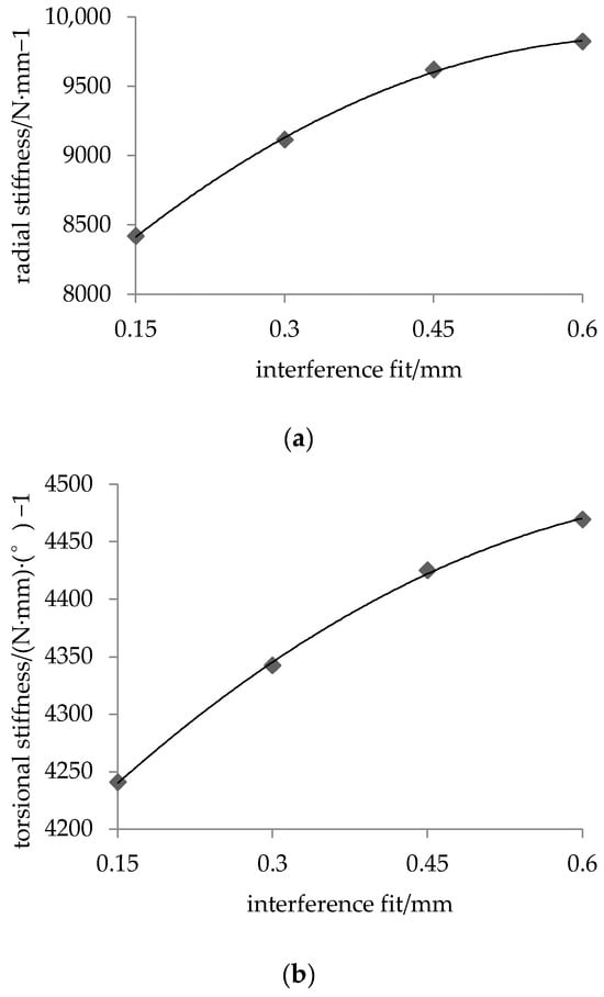
Figure 10.
Stiffness and Interference fit between the bushing and clamp variation curve; (a) Relationship between radial stiffness and Interference fit between the bushing and clamp fit variation, (b) Relationship between torsional stiffness and Interference fit between the bushing and clamp fit variation.
Figure 10 shows the relationship between the Anti-roll Bar stiffness and the change in interference at the bushing and clamp interface. Both the radial and torsional stiffness increase nonlinearly with the interference. The radial stiffness is significantly more sensitive to these changes than the torsional stiffness. The increase in interference from 0.15 mm to 0.6 mm results in a 16.7% increase in radial stiffness and a 5.4% increase in torsional stiffness.
The stiffness variation coefficient was calculated using Equation (6) for the bushing-clamp interface, where = 0.15 mm and is the stiffness value at this reference interference level. The relationship between this coefficient and the change in bushing and clamp interference is shown in Figure 11.
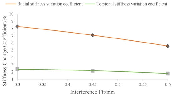
Figure 11.
Relationship between stiffness variation coefficient and Interference fit between the bushing and clamp fit variation.
- (1)
- As can be seen from Figure 11, the stiffness variation coefficients of the Anti-roll Bar are all positive, indicating that both the radial stiffness and torsional stiffness are proportional to the change in bushing and clamp interference, and that the stiffness of the Anti-roll Bar increases with the interference.
- (2)
- The coefficient of variation for radial stiffness is larger than that for torsional stiffness. This indicates that radial stiffness is more sensitive to changes in the bushing and clamp interference fit than torsional stiffness. Consequently, a change in this interference produces a more significant variation in radial stiffness than in torsional stiffness.
- (3)
- The coefficient of variation for radial stiffness decreases from 8.3% to 5.6% with increasing bushing and clamp interference, indicating that its influence on the Anti-roll Bar’s radial stiffness diminishes as the interference increases. The coefficient of variation for torsional stiffness also decreases with increasing interference, albeit slowly, from 2.4% to 1.8%. This smaller change, to that of radial stiffness, indicates that torsional stiffness is less sensitive to changes in the bushing and clamp interference fit.
3.7. Experimental Verification
Loading tests were conducted with a 1 mm interference fit between the bushing and rod, 2 mm between the bushing and base plate, and 0.6 mm between the bushing and clamp. The radial and torsional stiffness values obtained from these tests are presented in Table 4. Under identical interference conditions, the simulation yielded a radial stiffness of 9822.5 N/mm and a torsional stiffness of 4469.5 (N·mm)·(°)−1. The radial stiffness deviated from the experimental value by 1.8%, while the torsional stiffness showed a deviation of 0.7%. Both errors are minimal, validating the feasibility of the simulation model.

Table 4.
Anti-roll Bar Stiffness test value.
4. Conclusions
- (1)
- Based on Workbench simulation analysis, when the interference between the anti-roll bar and the bushing is 1 mm, the interference between the bushing and the base plate is 2 mm, and the interference between the bushing and the fixture is 0.6 mm, the radial stiffness is 9822.5 N/mm (deviation of 1.8%), and the torsional stiffness is 4469.5 (N·mm)·(°)−1 (deviation of 0.7%). All stiffness deviations fall within the 15% engineering tolerance standard, validating the rationality of the finite element interference simulation method.
- (2)
- The stiffness of the Anti-roll Bar increases with greater rubber bushing interference. A nonlinear relationship is observed between the Anti-roll Bar stiffness and the interference at both the bushing and rod and bushing and clamp interfaces. As the interference continues to increase, the rate of stiffness change becomes progressively slower. When the bushing and base plate interference increases, the variation trend of the torsional stiffness aligns with that observed when changing the other two interference values, while the radial stiffness exhibits a linear growth pattern.
- (3)
- Compared to the other two interference values, the stabilizer bar stiffness is more sensitive to changes in the bushing and rod interference and exhibits a larger coefficient of variation. In this case, the maximum coefficient of variation reaches 14.6% for radial stiffness and 6.2% for torsional stiffness, indicating that the bushing and rod interference has the greatest impact on the Anti-roll Bar stiffness. This is followed by the bushing and base plate interference, while the bushing and clamp interference has the least effect.
- (4)
- From the relationship between interference at the three locations and stiffness variation, it can be observed that the coefficient of variation for radial stiffness is greater than that for torsional stiffness. Therefore, when there is a need to modify the radial stiffness of the Anti-roll Bar while maintaining minimal change in torsional stiffness, adjusting the interference magnitude can be considered as an effective approach for stiffness tuning.
Author Contributions
Z.F.: data curation, formal analysis, software, validation, visualization, writing—original draft preparation, and writing—review and editing. Y.Y.: data curation, formal analysis, writing—review and editing, conceptualization, and funding acquisition. H.C.: data curation, methodology, writing—review and editing, conceptualization, supervision, and resources. S.X., Y.Z., S.Z.: data curation and validation. S.L.: investigation and validation. All authors have read and agreed to the published version of the manuscript.
Funding
This research was funded by the Shanghai Oriental Talent Top Project (Hao Chen), and the APC was funded by Project of Promoting Research Paradigm Reform and Empowering Disciplinary Leap through Artificial Intelligence (2024AI011) from the Shanghai Municipal Education Commission (Hao Chen).
Institutional Review Board Statement
Not applicable.
Informed Consent Statement
Not applicable.
Data Availability Statement
The data presented in this study are available on request from the corresponding author. The data are not publicly available due to technical confidentiality.
Acknowledgments
Thanks for the help on simulation analysis related works from Reliability and Lightweight Design Lab, Shanghai University of Engineering Science, Shanghai, China.
Conflicts of Interest
The authors declare no conflicts of interest.
References
- Mohanavel, V.; Iyankumar, R.; Sundar, M.; Kumar, P.K.; Pugazhendhi, L. Modelling and finite element analysis of anti-roll bar using ANSYS software. Mater. Today Proc. 2020. prepublish. [Google Scholar] [CrossRef]
- Cronjé, P.; Els, P. Improving off-road vehicle handling using an active anti-roll bar. J. Terramech. 2009, 47, 179–189. [Google Scholar] [CrossRef]
- Cerit, M.; Nart, E.; Genel, K. Investigation into effect of rubber bushing on stress distribution and fatigue behaviour of anti-roll bar. Eng. Fail. Anal. 2010, 17, 1019–1027. [Google Scholar] [CrossRef]
- Nie, Z. Finite Element Analysis And Experimental Research On Static Stiffness Of Rubber Bushing. Master’s Thesis, Qingdao University of Science and Technology, Qingdao, China, 2021. (In Chinese). [Google Scholar] [CrossRef]
- Lü, Z.; Zhang, H.; Yue, Z.; Lang, F.; Huang, Y. Optimization of rear rubber bushing of front suspension stabilizer rod assembly for heavy tractor cab. Agric. Equip. Veh. Eng. 2024, 62, 70–72. (In Chinese) [Google Scholar]
- Kumar, Y.; Siddiqui, R.A.; Upadhyay, Y.; Prajapati, S. Kinematic and Structural Analysis of Independent type suspension system with Anti-roll Bar for Formula Student Vehicle. Mater. Today Proc. 2022, 56, 2672–2679. [Google Scholar] [CrossRef]
- Hassan, M.; Elsayed, A.; El-Souhily, B.; Elgamal, H.; Elshabasy, M.M.Y.B. Investigating the effect of augmenting the anti-roll-bar with a torsional-dynamic-absorber on the handling-stability and the ride-comfort of the off-road-vehicles. Alex. Eng. J. 2023, 81, 29–45. [Google Scholar] [CrossRef]
- Pan, H. Structural Optimization Design of a Vehicle Lateral Stabilizer Bar. Automob. Appl. Technol. 2023, 48, 87–91. (In Chinese) [Google Scholar] [CrossRef]
- Junik, K.; Lesiuk, G.; Barcikowski, M.; Błażejewski, W.; Niemiec, A.; Grobelny, M.; Otczyk, K.; Correia, J.A.F.O. Impact of the hardness on the selected mechanical properties of rigid polyurethane elastomers commonly used in suspension systems. Eng. Fail. Anal. 2021, 121, 105201. [Google Scholar] [CrossRef]
- Brown, A.M.; Evans, L.J. Fatigue life variability due to variations in interference fit of steel bushings in 7075-T651 aluminum lugs. Int. J. Fatigue 2012, 44, 177–187. [Google Scholar] [CrossRef]
- Nizev, V.; Polushkin, O.; Kireev, S.; Stepanov, V. Fatigue Strength of an Aircraft Wing Panel with a Repair Patch Based on the Filled Hole at Various Values of Interference Fit. Transp. Res. Procedia 2021, 54, 150–156. [Google Scholar] [CrossRef]
- Wei, J.; Jiao, G.; Jia, P.; Huang, T. The effect of interference fit size on the fatigue life of bolted joints in composite laminates. Compos. Part B 2013, 53, 62–68. [Google Scholar] [CrossRef]
- Li, J.; Zhang, K.; Li, Y.; Liu, P.; Xia, J. Influence of interference-fit size on bearing fatigue response of single-lap carbon fiber reinforced polymer/Ti alloy bolted joints. Tribol. Int. 2016, 93, 151–162. [Google Scholar] [CrossRef]
- Shu, Y.; Yang, G.; Liu, Z. Simulation research on fretting wear of train axles with interference fit based on press-fitted specimen. Wear 2023, 5, 23. [Google Scholar] [CrossRef]
- Le Falher, M.; Fouvry, S.; Arnaud, P.; Maurel, V.; Antoni, N.; Billardon, R. Fretting-fatigue of shrink fit lug-bush assemblies: Interference-fit effect. Tribol. Int. 2023, 186, 108581. [Google Scholar] [CrossRef]
- Wang, A.; Wang, Z.; Zhao, M.; Zhao, Y.; Chang, Z. Effects of ply thickness and interference-fit on the bearing strength of single-lap countersunk composite joints. Thin-Walled Struct. 2023, 189, 110878. [Google Scholar] [CrossRef]
- Xu, G.; Li, X.; Zhu, Y. Support stiffness effects on damage behavior of thin-walled composite interference-fit joints in the installation. Eng. Fail. Anal. 2024, 156, 107841. [Google Scholar] [CrossRef]
- Tarlochan, F.; Mehboob, H.; Mehboob, A.; Chang, S.-H. Biomechanical design of a composite femoral prosthesis to investigate the effects of stiffness, coating length, and interference press fit. Compos. Struct. 2018, 204, 803–813. [Google Scholar] [CrossRef]
- Elvio, B.; Gabriele, M.; Simone, V. Interference fit estimation through stress-stiffening effect on dynamics. Mech. Syst. Signal Process. 2021, 160, 107919. [Google Scholar] [CrossRef]
- Karale, A.; MohanKumar, V.; Rane, S. Evaluate slip torque of an interference fit using preloaded non-linear large strain simulation in MSC MARC. Mater. Today Proc. 2023, 72, 1890–1895. [Google Scholar] [CrossRef]
- Millan, M.; Booker, J.; Smith, D.; Onisa, C.F.; Korsunsky, A.; Song, X.; Baimpas, N.; Evans, A. Analysis of increasing torque with recurrent slip in interference-fits. Eng. Fail. Anal. 2016, 62, 58–74. [Google Scholar] [CrossRef]
- Xiao, X.; Zhao, S.; Yu, H.; Huang, Y.; Long, D. Finite Element Analysis and Fatigue Calculation on Stabilizer-bar with Rubber Bushing. In Proceedings of the 2020 Annual Conference of the Society of Automotive Engineers of China (4), Shanghai, China, 27 October 2020; China Society of Automotive Engineers: Beijing, China, 2020; pp. 697–701. (In Chinese). [Google Scholar]
- Bai, S.; Zhang, W.; Yan, L. Finite Analysis of a Truck Stabilizer Bar. Automob. Appl. Technol. 2015, 1–3. (In Chinese) [Google Scholar] [CrossRef]
Disclaimer/Publisher’s Note: The statements, opinions and data contained in all publications are solely those of the individual author(s) and contributor(s) and not of MDPI and/or the editor(s). MDPI and/or the editor(s) disclaim responsibility for any injury to people or property resulting from any ideas, methods, instructions or products referred to in the content. |
© 2025 by the authors. Licensee MDPI, Basel, Switzerland. This article is an open access article distributed under the terms and conditions of the Creative Commons Attribution (CC BY) license (https://creativecommons.org/licenses/by/4.0/).