Article

Effect of Crease-Weakening Schemes on the Structural Performance of Lightweight Foldable Columns Based on the Pillow Box Pattern

1
School of Civil Engineering, Southeast University, Nanjing 211189, China
2
School of Civil Engineering, University of Queensland, St. Lucia 4072, Australia
*
Author to whom correspondence should be addressed.
Appl. Sci. 2025, 15(19), 10756; https://doi.org/10.3390/app151910756
Submission received: 25 August 2025 / Revised: 24 September 2025 / Accepted: 26 September 2025 / Published: 6 October 2025

Abstract

Origami structures exhibit significant potential for rapid deployment in post-disaster response and temporary architecture due to their ability to quickly fold and deploy. Further development of these structures into modular components that can be assembled into large-scale architectural systems holds great importance for the fields of architecture and civil engineering. In this study, a thin-walled foldable column was developed based on the “pillow box” origami pattern. This column maintains its three-dimensional configuration during folding, owing to its inherent self-locking characteristic. Two crease-weakening strategies (“dashed-line” and “slit-hole”) were proposed and experimentally validated. A systematic numerical study was conducted to investigate the axial compressive performance of pillow box columns with weakened curved creases. The results indicate that both weakening strategies effectively enable folding while preserving global integrity under compression. The pillow box column with “dashed-line” creases (OCC-D) demonstrated superior load-bearing capacity, with a load-to-weight ratio of up to 658.9, nearly twice that of the corresponding conventional square tube. Parametric analysis of the crease geometry further revealed that increasing the number of crease units enhances the load-bearing performance, and the optimal performance is achieved when the spacing between slit openings equals the slit length ( l h = l c ). These findings highlight the advantages of pillow box origami columns as thin-walled load-bearing components, offering new insights for the rapid construction and lightweight design of architectural structures.

1. Introduction

1.1. Origami-Inspired Architectural Structures

In recent years, origami-inspired structures have attracted significant attention in civil engineering and architecture due to their excellent foldability and rapid deployability, especially for temporary and deployable applications [1,2,3,4]. They are particularly suitable for post-disaster response and recovery scenarios, offering a novel technical pathway for fast and efficient construction [5,6,7,8,9,10].
Beyond deployability, origami structures also offer important advantages in lightweight construction. Existing research includes both thin-walled origami structures and thick-panel folding systems. Thin-walled designs are primarily applied in shelter construction [5,10,11,12,13,14], where they can be rapidly deployed from a flat configuration to meet the urgent needs of post-disaster deployment, as well as in temporary and conceptual architectural installations [15,16,17,18]. However, such systems often suffer from limited spatial flexibility and insufficient load-bearing capacity.
Thick-panel folding systems [19,20,21] can remain flat during transport and be folded on-site, offering better structural performance. Yet, the inherent panel thickness restricts pre-bending, hindering further lightweight optimization. In contrast, thin-walled panels are more suitable for folding and bending into desired shapes, thereby providing superior mechanical performance [22].
To fully exploit the advantages of origami structures and achieve a balance between lightweight construction and structural load-bearing capacity at architectural scales, some studies have explored discrete or block-wise assembly approaches [23]. These involve pre-folding small structural units and assembling them into deployable structures. However, at the architectural application level, only a limited number of studies have investigated the use of foldable modules to construct non-deployable structures [24,25,26].

1.2. Crease-Weakening Schemes

In thin-walled origami structures, common crease fabrication methods include mechanical scoring, partial-depth cutting, and full-depth cutting [23,27,28,29,30]. For instance, molds were used to imprint creases in prototype fabrication [31,32]. However, mechanical scoring requires customized molds, which are inefficient for complex crease patterns and difficult to implement. Moreover, the pre-impressed creases are not true fold lines and cannot achieve complete deployment and re-folding.
Polycarbonate sheets have also been processed using fabric hinges, as demonstrated in [13]. However, hinge-based connections act similarly to pin joints, which hinder coordinated deformation between panels and are, therefore, unsuitable for load-bearing components.
In contrast, introducing pre-cut holes along the creases to weaken them can facilitate coordinated panel deformation and is applicable to arbitrary crease patterns. This approach fully leverages the advantages of foldable structures and enables the rapid construction of thin-walled systems.
Nevertheless, the introduction of holes introduces material discontinuity at the creases, which reduces crease stiffness and thereby affects structural performance [33,34,35,36] and fatigue performance [36,37,38,39,40]. Most existing studies focus on the effects of weakening creases on folding behavior [41,42,43,44,45]. It has been shown that the shape and aspect ratio of the cut-out holes significantly influence folding capacity and crease stiffness [28,46].

1.3. Research Contribution

In summary, current research on large-scale foldable structures has primarily focused on architectural form exploration, while studies investigating the mechanical performance of thin-walled foldable structures as load-bearing components remain limited. This gap is particularly critical for enabling technological innovations in developing new structural systems. Moreover, existing studies tend to address macroscopic architectural aspects, with insufficient attention paid to how specific crease-weakening designs affect the mechanical behavior of thin-walled folded structures. Addressing this issue may significantly expand both the application scope and performance potential of deployable structures.
This paper aims to elucidate the role of crease-weakening schemes in the mechanical performance of pillow box origami columns. These columns represent a novel type of geometrically self-locking, rapidly deployable thin-walled members with curved creases. Moreover, its cross-sectional curvature matches that of the column body, enabling rapid assembly. Building upon this foundation, two representative weakening strategies—the dashed-line type and the slit-hole type—are designed and compared through finite element analysis(FEA). Straight-crease columns (OSC) and conventional tubular columns are also introduced as benchmarks to highlight structural advantages. The specific contributions are as follows: (i) introducing the slit-hole weakening scheme and comparing it numerically with the dashed-line scheme; (ii) conducting systematic finite element analyses to compare the mechanical performance of OCC, OSC, and TCC under both weakening schemes; and (iii) the superior weakening form between the two types is selected, followed by a parametric study to provide design recommendations for key parameters.
Section 2 introduces the geometry and fabrication feasibility of the thin-walled columns with weakened creases, validated through physical prototyping. Section 3 presents numerical simulations on the axial compression performance of different origami column variants with various crease-weakening strategies. Section 4 conducts parametric studies on the weakened creases. Section 5 discusses the performance enhancements of the pillow box origami column compared to conventional tubular columns and provides recommendations for the selection of crease-weakening parameters.

2. Materials and Methods

2.1. Structural Concept and Geometric Design

2.1.1. Modular Unit Configuration

The pillow box configuration is commonly used in packaging due to its excellent deployability and self-locking characteristics [47]. It enables a rapid transition from a flat state to a folded state, while maintaining the folded shape without the need for additional fastening components. Based on these advantages, this study proposes a fundamental frame system assembled using pillow box units as structural modules, as illustrated in Figure 1. The structural units are connected via end caps that conform to the cross-sectional geometry of the pillow box. One of the primary design objectives is to achieve rapid construction, while another is to realize lightweight architecture by utilizing the initial curvature-induced prestress inherent in curved-crease origami. The primary focus of this study is the investigation of the mechanical behavior of the column component shown in the figure.
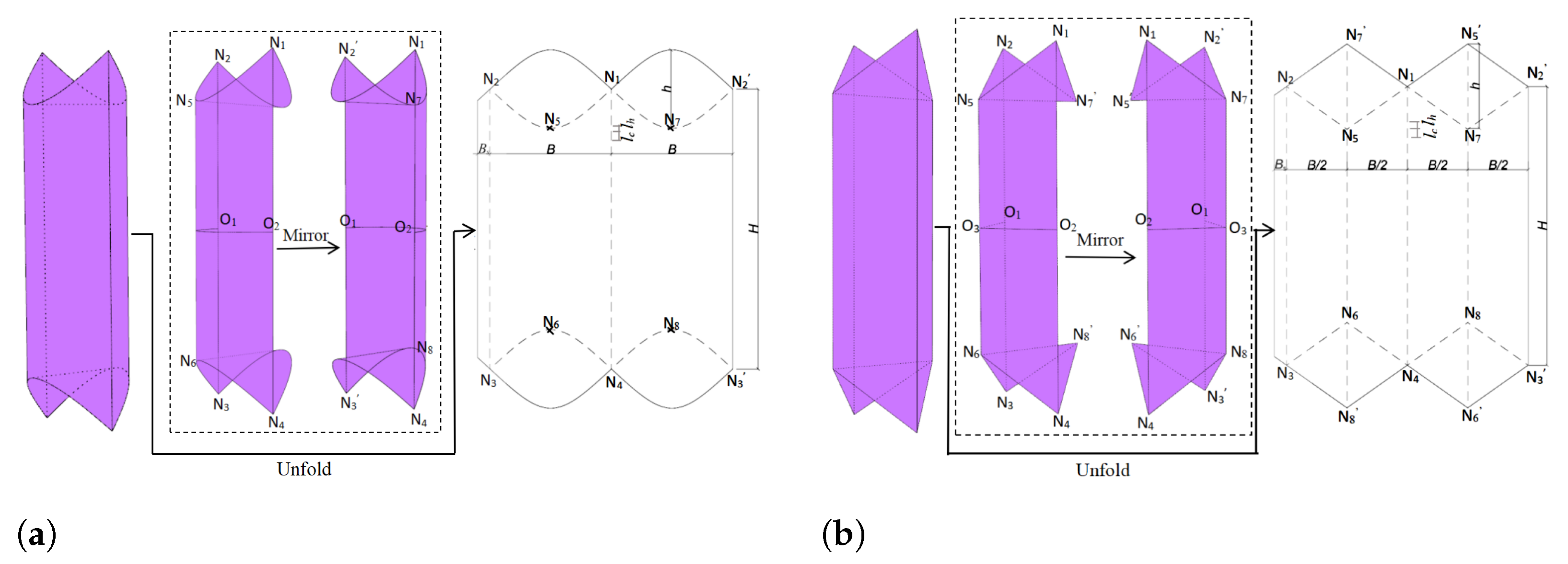
The pillow box column, also referred to as an origami with curved creases column (OCC), is generated from an initial curved surface defined by the arc O 1 O 2 [48]. This surface is symmetrically extended by mirror reflection across two inclined planes passing through node pairs N 1 , N 2 and N 3 , N 4 , respectively, with each inclined at 45 to the vertical. The result is a symmetric single-crease origami configuration. The pillow box geometry is formed by combining this configuration with its mirror image across the vertical plane, yielding a closed, self-locking form. The detailed crease pattern and geometric dimensions are shown in Figure 2a, where dashed lines indicate fold lines. Here, B denotes the arc length of O 1 O 2 , H represents the height of the OCC, h denotes the width of the column in its folded state, and B s indicates the assembly seam allowance. The geometry can be uniquely determined by the above parameters. In addition, to gain deeper insight into the influence of pre-bending on mechanical performance, a corresponding origami column with straight creases (OSC) is designed for comparison. The configuration of the OSC is generated through a process analogous to that of the OCC, as illustrated in Figure 2b.
To investigate the potential of the OCC concept for lightweight architectural applications, foldable traditional tubular columns are introduced as benchmarks, as shown in Figure 3. These include the tubular column with curved creases (TCC) and the tubular column with straight creases (TSC), the latter of which represents a conventional foldable square tube column.

2.1.2. Crease Design

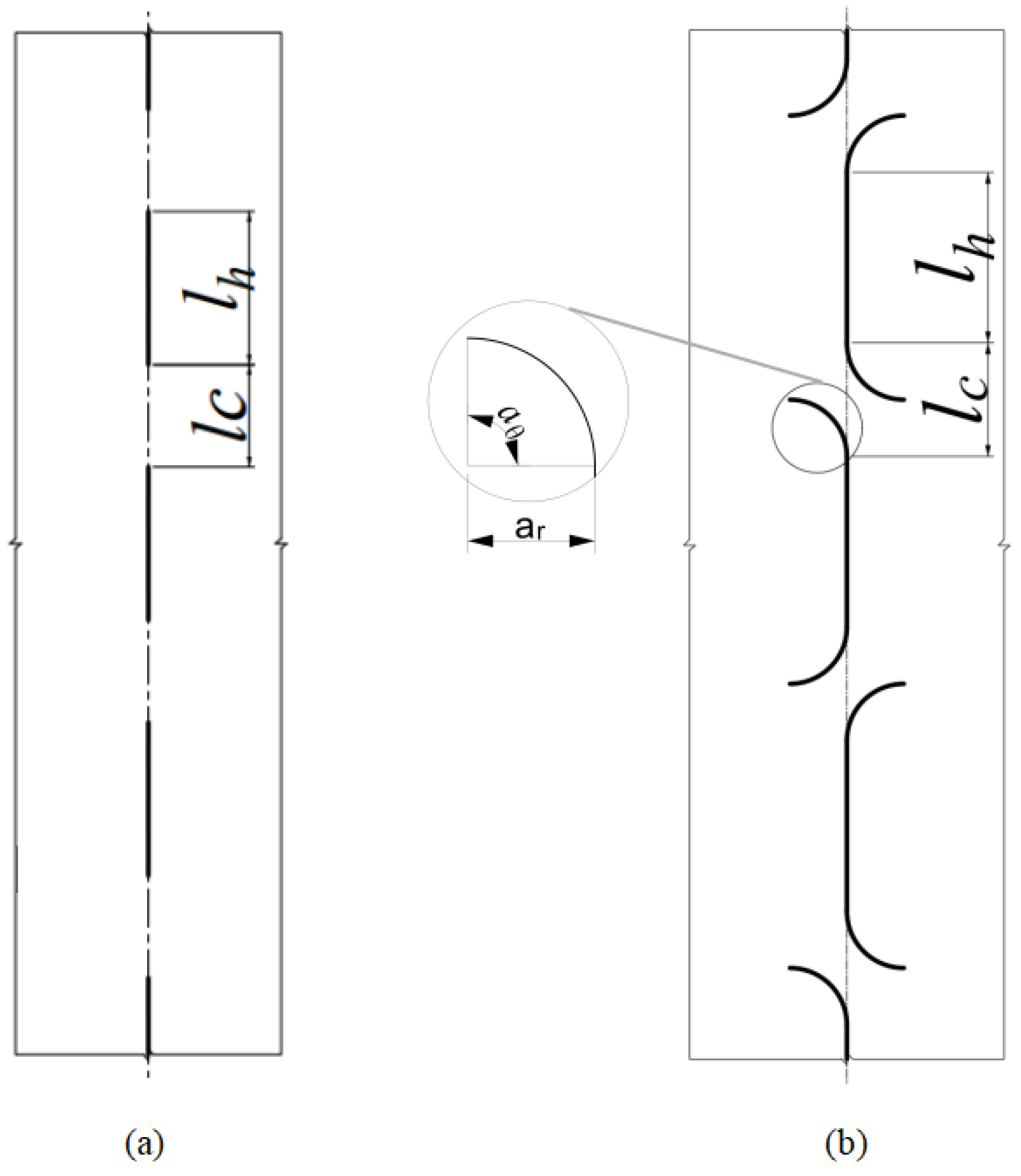
To investigate the influence of crease-weakening schemes on the mechanical performance of pillow box origami columns, this study adopts two commonly used patterns [33,46], as follows: the “dashed-line” type featuring elongated cut slits, and the “slit-hole” type characterized by crescent-shaped openings. Both patterns have been demonstrated to facilitate precise folding in thin-walled materials while maintaining overall structural integrity during loading, as discussed in Section 2.2. Detailed configurations are illustrated in Figure 4. Here, l c denotes the length of the connected crease segments, l h is the length of the cut segments, and for the slit-hole type, a r is the radius of the arc, and a θ represents the central angle.

2.2. Validation of Crease Fabrication and Simulation

A simplified validation focusing on the effectiveness of crease-weakening was further conducted in this study using TCC specimens. The TCC configuration, with its simpler geometry and absence of self-locking effects, allows the influence of crease-weakening schemes (dashed-line vs. slit-hole) to be examined without interference from additional geometric complexities. Meanwhile, to ensure that the failure mode of the origami columns was governed by local buckling rather than overall flexural buckling, the specimens were designed as short columns (H/B < 3), so as to focus on the mechanical influence of different crease types.

2.2.1. Experiment

Considering the goal of lightweight applications and foldability, polypropylene (PP) was selected as the prototype material. The PP sheets were laser-cut according to the pattern shown in Figure 3a, and the vertical seams were bonded using high-strength acrylic double-side tape for plastics, metals, and glass, which can resist an adhesive force of approximately 200 N per meter. One specimen was fabricated for each crease-weakening type. PPC1T1D denotes the specimen with dashed-line creases, and PPC1T1H denotes the specimen with slit-hole creases, shown in Figure 5. All specimens share the same global dimensions: width B = 250 mm , height H = 390 mm , folded cross-sectional width h = 170 mm , and thickness t = 0.8 mm . Each unit has a perforated segment length l h = 15 mm and a connecting segment length l c = 10 mm . Additionally, for the slit-hole specimen, a r = 5 mm , and a θ = 90 .
Columns were tested on a 50 kN capacity Instron Universal Testing Machine with the experimental setup shown in Figure 6. A displacement-controlled loading protocol was applied at a constant rate of 1 mm/min. The end fixtures were mounted between the column and the Instron loading plates, and the customized end caps for each column type are shown in Figure 6. These end caps were CNC-milled from 17 mm thick wood panels with grooves reserved to secure the shape of the TCC, and were bolted onto the testing machine. Axial load and displacement were recorded using Instron’s built-in load cell and displacement sensor.

2.2.2. Numerical Model

The detailed modeling procedure is provided in Section 3. For both types of crease-weakening schemes, the perforation patterns were modeled with full geometric fidelity according to their actual dimensions. For vertical creases, tie constraints were applied to non-perforated regions in the physical prototype, while the rotational degrees of freedom were released, and remain unconnected at other locations. The boundary conditions of the numerical model were adjusted to match the experimental setup—since the column specimens in the crease tests were confined within the grooves of the top and bottom loading ends, all degrees of freedom were constrained, and the model was therefore defined as fully fixed at both ends, with the exception of the translational degree of freedom in the z-direction at the upper loading end. All other settings remained unchanged.
The elastic–plastic properties of PP were obtained from tensile tests; the Young’s modulus and yield stress were 1134.06 MPa and 10.64 MPa, respectively. The constitutive relationship curve of the material is shown in Figure 7. Due to equipment limitations, the Poisson’s ratio could not be recorded, so a value of ν = 0.38 was adopted based on values reported in [49].

2.2.3. Results

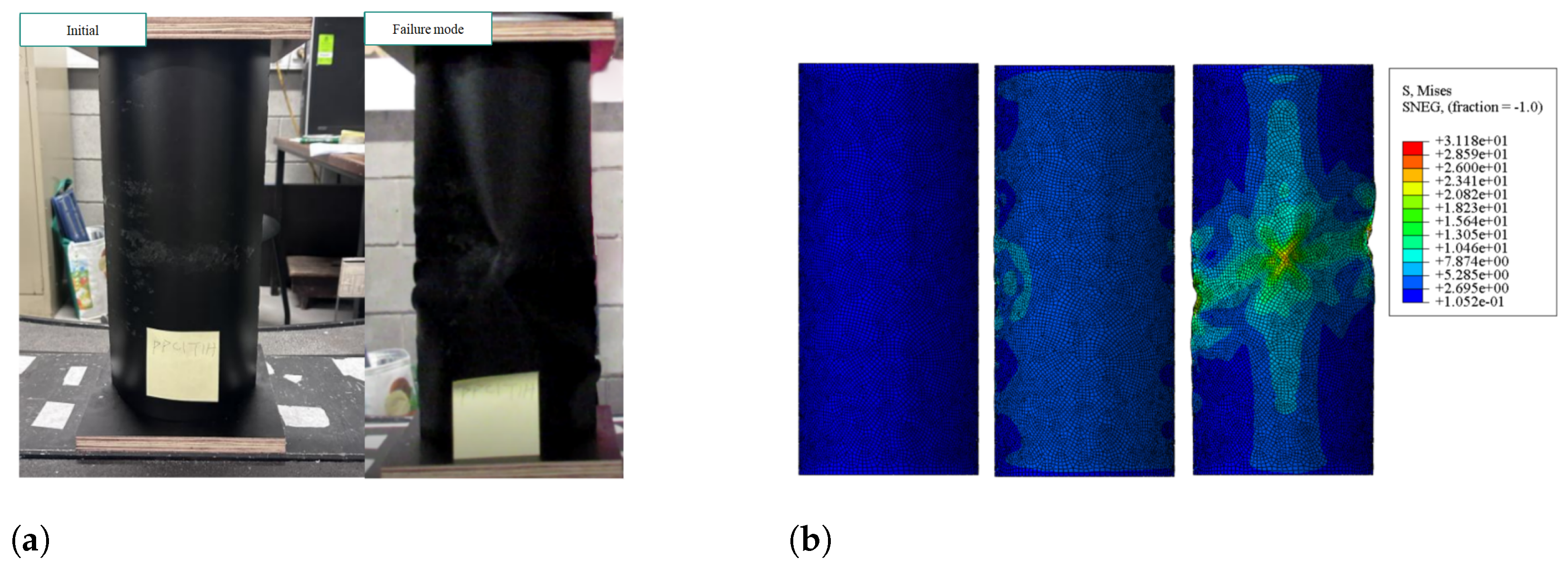
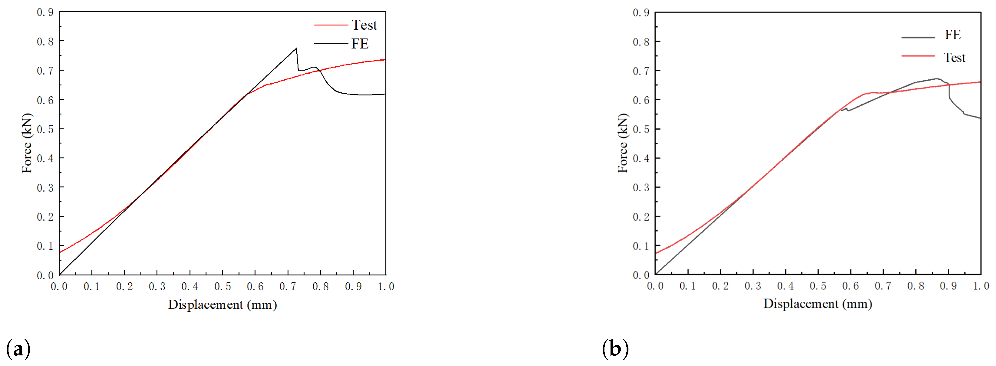
The axial compression experimental and finite element results of the two types of columns are shown in Figure 8, Figure 9 and Figure 10, and the corresponding peak loads and structural stiffness values are summarized in Table 1. In this study, the structural stiffness is defined as the initial elastic stiffness, obtained from the slope of the load–displacement curve in the linear elastic stage. To eliminate the influence of the inevitable specimen–fixture settling and gradual contact effects at the beginning of the test, the initial non-linear branch of the experimental load–displacement curves was excluded from the analysis. The linear elastic portion was extended, and a new origin was defined, which resulted in a small horizontal shift of the experimental curves. This adjustment enables a clearer comparison with the finite element predictions, and follows a common practice adopted in experimental studies [8]. It can be observed that the finite element model provides a good prediction of the experimental behavior, with both showing local buckling occurring at the mid-height of the columns. The differences between the finite element predictions and experimental values for both peak load and stiffness are within 1.3–3.0%, indicating good accuracy.

3. Numerical Analysis

3.1. Numerical Model

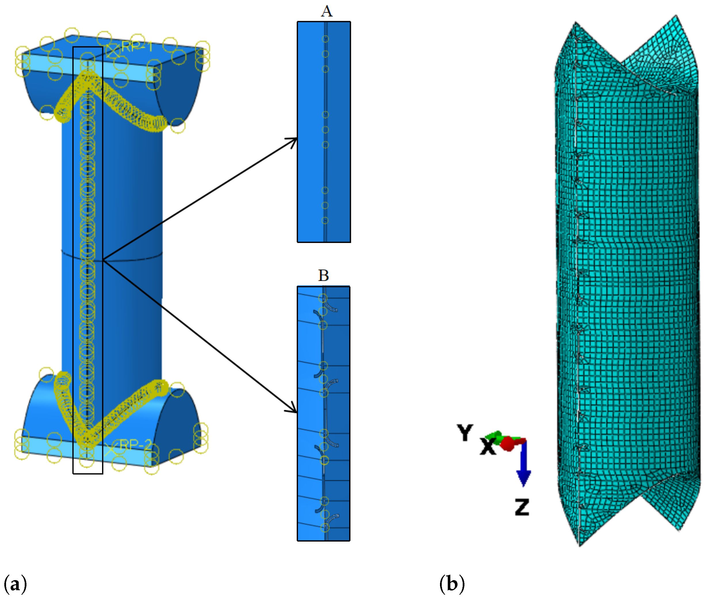
To further investigate the mechanical performance of the pillow box origami columns, shown in Figure 11a, finite element analyses were first conducted on all column types introduced in Section 2.1.1. The numerical model was developed in the finite element software ABAQUS 2021. For each column type, two crease-weakening schemes—dashed-line and slit-hole—were applied, resulting in a total of eight finite element models. The column is meshed with four-node S4R shell elements (shown in Figure 11b), which feature reduced integration, hourglass control, and finite membrane strains, and have been widely applied in the analysis of origami thin-walled structures [50,51]. The element size of 5 mm was determined through a mesh convergence study [50,52]. The top and bottom panels were simplified to be modeled as a single surface with double thickness, rather than two lapped surfaces. Each panel of the column is modeled as a separate part. At the end, creases, panels are connected using tie constraints, which act as idealized hinges with zero rotational stiffness. At side creases, tie constraints are applied to non-perforated regions in the physical prototype and remain unconnected at other locations. The end caps were modeled using eight-node C3D8R solid elements with a mesh size of 10 mm and defined as rigid bodies. Rigid control points were used to constrain end caps. The bottom end cap was fully fixed, and the top end cap was free to translate along the z-axis only. General contact was defined between the column surface and end caps. Additionally, the scaled shapes of eigenmodes were introduced into the nonlinear analyses as initial geometric imperfections. The scaling factor was set to 1/1000. This two-tier validation ensures that the adopted finite element framework achieves both global accuracy (OCC/OSC validation) and local reliability (TCC validation of crease-weakening schemes).
All specimens share the same basic dimensions—width B = 195 mm , height H = 450 mm , and thickness t = 0.8 mm . Each column consists of n = 18 crease units, where each unit includes a connection segment of length l c = 10 mm and a hole segment of length l h = 15 mm . The varying parameters a r and a 0 for different crease-weakening types are summarized in Table 2. For all models, a displacement-controlled loading of 10 mm was applied.

3.2. Numerical Results

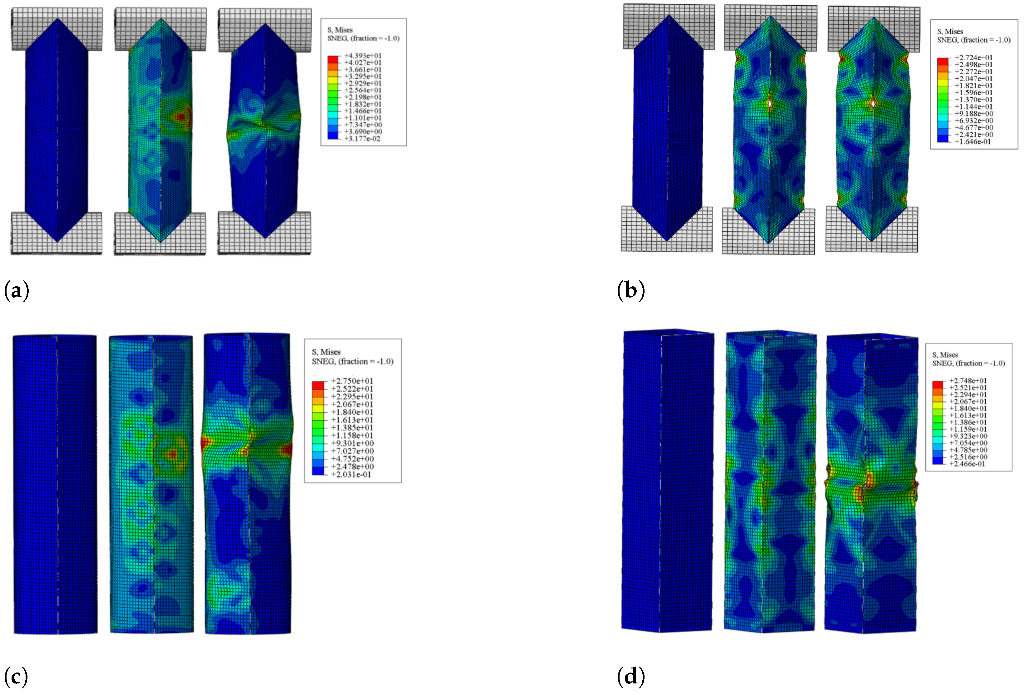
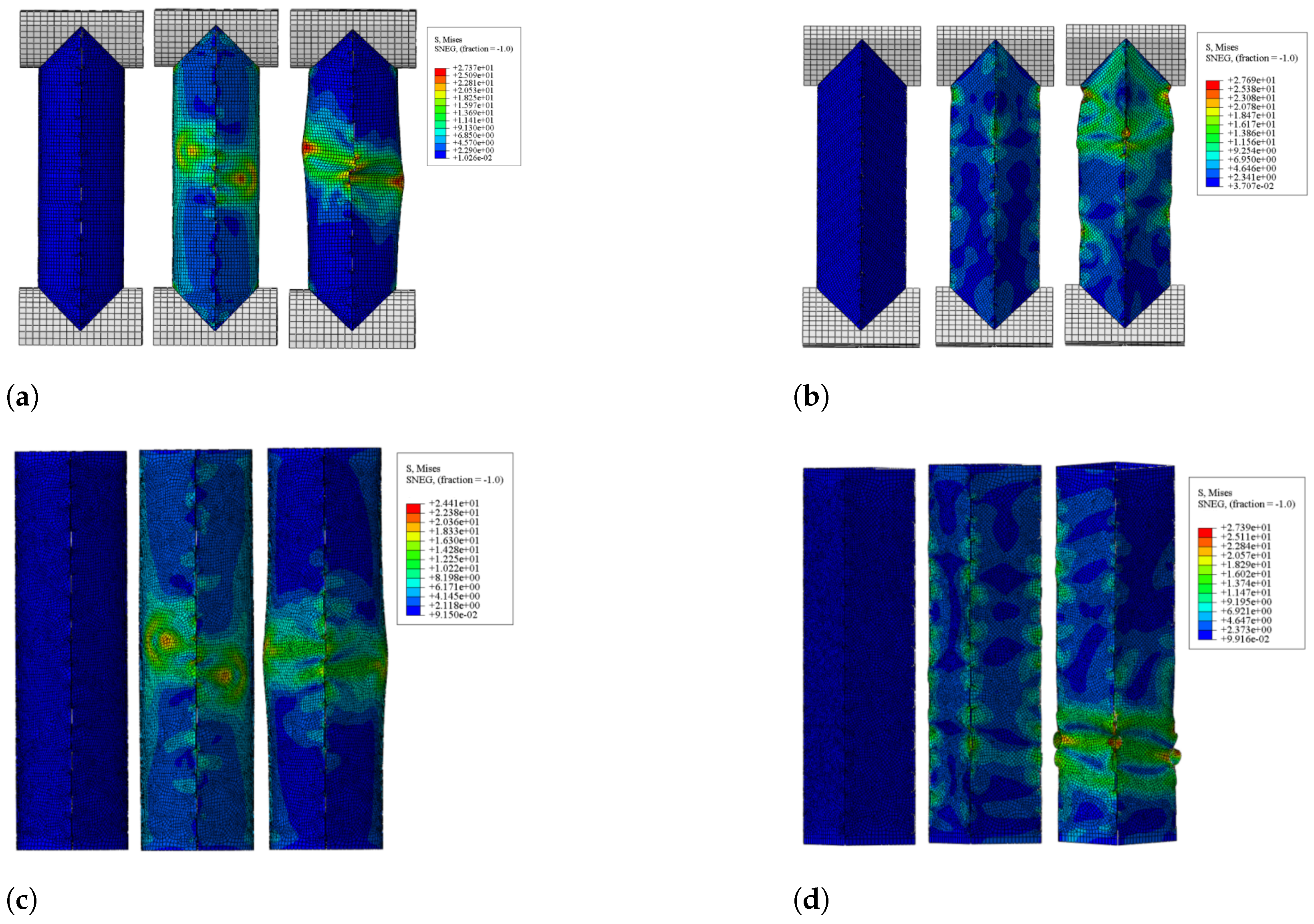
The axial deformation and stress distributions of all specimens are shown in Figure 12 and Figure 13. It can be observed that under axial compression, all columns exhibit a common behavior—after reaching the peak load, the stress becomes highly concentrated along the crease lines. This is attributed to the geometric discontinuity at the creases, which possess relatively lower local stiffness and are prone to early buckling. As the loading continues, all specimens eventually undergo local buckling failure, with pronounced plastic deformation and stress concentration developing along the creases. The results indicate that the curved-crease panels generate circumferential pre-tension due to their initial pre-bending geometry, which causes the arc apex to experience the highest stress at the early loading stage. As the external load increases, stress progressively transfers to the creases, which sustain higher stress levels prior to buckling. Meanwhile, the self-locking effect restricts relative panel motion and effectively raises the critical buckling stress, thereby enhancing the overall load-bearing capacity. In contrast, straight-crease structures lack curvature-induced pre-tension, with stress consistently concentrated along the crease lines, leading to earlier instability and substantially lower ultimate strength and structural stability compared to curved-crease counterparts.
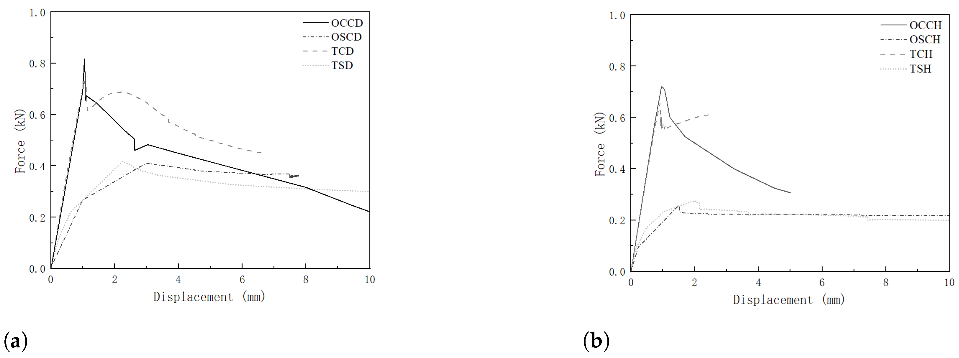
The load–displacement responses of all columns are presented in Figure 14. It can be observed that OCC and TCC exhibit similar stiffness and peak load capacities, both significantly higher than those of OSC and TSC. This indicates that the pre-bending of curved-surface structures contributes to improved load-bearing performance of thin-walled columns. Additionally, as shown in Table 3, columns with the “dashed-line” pattern achieve higher peak loads compared to their “slit-hole” counterparts. Specifically, within the OCC series, OCC-D exhibits a 13.9% higher peak load compared to OCC-H, while its stiffness is marginally lower by 2.7%. This may be attributed to the fact that “dashed-line” creases introduce localized stress concentrations, leading to more pronounced weak zones and resulting in slightly lower initial stiffness. However, the “dashed-line” configuration is capable of activating multiple small-scale buckling modes, thereby distributing deformation over a larger area and providing more potential buckling paths, as also evidenced in Figure 12 and Figure 13. Consequently, OCC-D demonstrates a higher load-bearing capacity and forms a structurally more robust system. Further details will be discussed in Section 5.2.

4. Influence of Design Parameters on Mechanical Response

Results in Section 3 indicate that the OCC-D specimen exhibits the best load-bearing performance among all tested configurations. Therefore, this section conducts a parametric analysis of OCC-D by varying crease design parameters, with the aim of thoroughly investigating the influence of crease geometry on the load-bearing capacity of the OCC column, thereby laying the foundation for design optimization.
Two primary design parameters are considered: Two primary design parameters are considered: the porosity ϕ , defined as the ratio of the open area, and the number of repeating dashed-line units along the crease direction, denoted as n. A total of six specimens in two comparison groups are analyzed, with the specific values listed in Table 4.
The total number of crease units n and the open-area ratio (porosity) ϕ are calculated, respectively, as follows:
n = H l c + l h
ϕ = l h l c + l h
where H denotes the total length of the structure along the crease direction.

4.1. Porosity ϕ

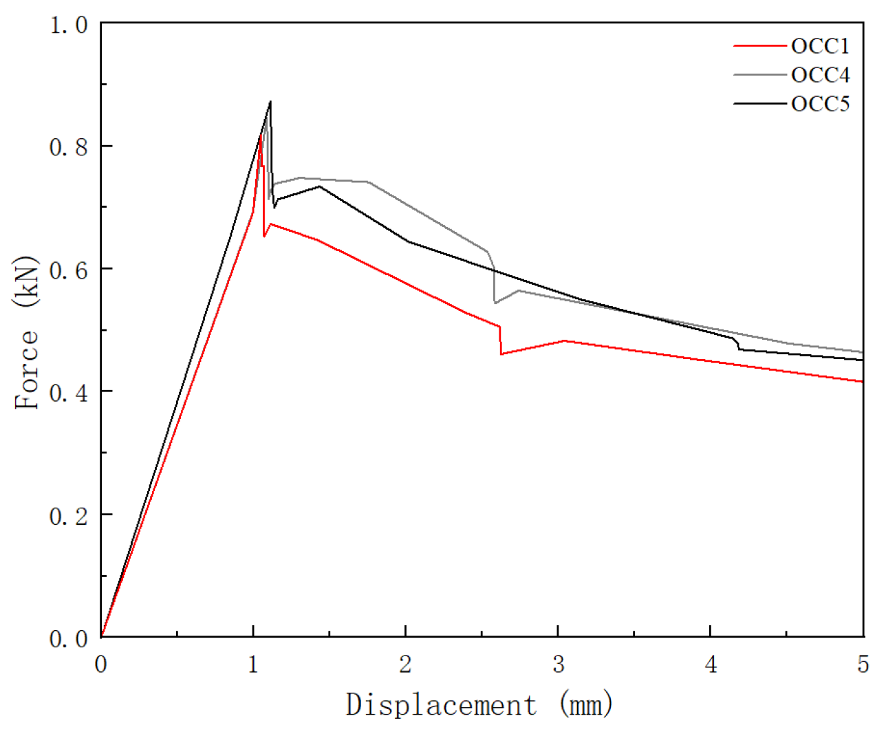
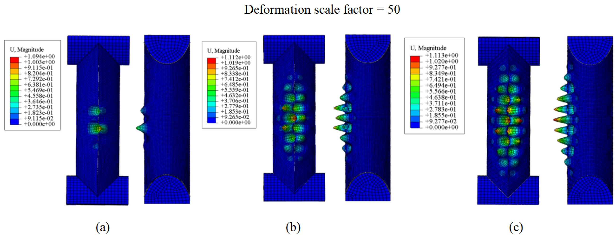
Three OCC-D specimens with different porosities were designed, namely OCC1, OCC4, and OCC5, with porosity values ranging from 0.4 to 0.6. Among them, OCC1 corresponds to the OCC-D specimen previously analyzed in Section 3. The failure modes at a displacement of 5 mm and the corresponding load–displacement curves of all specimens are shown in Figure 15 and Figure 16, respectively.
Finite element analysis results indicate that the axial compression performance of OCC-D columns is influenced by the geometric parameters of the crease, particularly the ratio between the length of the connecting segment ( l c ) and the open segment ( l h ). When l c = l h , a three-stage buckling pattern develops along the column height. This manifests a more distributed and stable failure mode, suggesting that equal lengths of the connecting and open segments lead to more uniform geometric discontinuities along the column height. Such uniformity promotes multi-point buckling modes and mitigates stress concentration, resulting in a more even stress distribution that prevents any single “weak” location from bearing the entire compressive stress. This is further supported by OCC5 exhibiting the lowest maximum stress among the three columns. Moreover, combining the load–displacement curves and Table 5, it can be seen that the column with l c = l h has higher stiffness and the highest load capacity, with stiffness and peak load increasing by 5.4% and 6.1%, respectively, in comparison to OCC1, demonstrating optimal load-bearing performance consistent with the observed failure modes. In contrast, the columns with l c > l h and l c < l h exhibit similar stiffness, but the former has a slightly higher load capacity. This is because a longer connecting segment length l c provides a longer effective load-bearing path under axial compression, better resisting compressive deformation, and slightly delaying the onset of local buckling.

4.2. Number of Crease Units n

Three OCC-D specimens with different numbers of repeating units were designed, namely, OCC1, OCC2, and OCC3, with n values of 18, 36, and 9, respectively. Among them, OCC1 corresponds to the OCC-D specimen previously analyzed in Section 3. The failure modes at a displacement of 5 mm and the corresponding load–displacement curves of all specimens are shown in Figure 17c and Figure 18, respectively.
The finite element results indicate that the axial compressive performance of OCC-D columns is influenced by the number of units n. As shown in Figure 16, OCC2 exhibits symmetric deformation, consistent with the axial crushing mode of short columns, whereas OCC1 and OCC3 display asymmetric lateral buckling. The results indicate that, under the same porosity, a greater number of crease units leads to more evenly subdivided weakening, which induces symmetric and multi-point cooperative buckling patterns, thereby effectively dispersing stress concentration and enhancing the overall load-bearing performance. In comparison, OCC2 (36 units) demonstrates the best performance, with a well-organized symmetric buckling mode and the highest peak load; OCC1 (18 units) ranks second, still showing some local concentration; whereas OCC3 (9 units), due to its sparse crease distribution, exhibits highly localized stress concentration, premature buckling, and the lowest peak load. Overall, an appropriate increase in crease density not only reduces the extent of local weakening but also improves column stability and ultimate load capacity. This phenomenon will be discussed in detail in Section 5.1.
Based on Figure 17 and Table 6, it is evident that as n increases, the stiffness of the OCC columns gradually decreases, while the peak load steadily increases. Specifically, the stiffness of OCC2 is 11.5% lower than that of OCC3, yet its peak load is 20.0% higher. This may be attributed to the fact that a greater number of units leads to more hinge-like segments arranged in series, thereby reducing the initial elastic stiffness of the structure. Meanwhile, the higher crease density facilitates more uniform and coordinated development of buckling deformation, which in turn enhances the ultimate load-bearing capacity of the column.

5. Discussion

5.1. Parameter Analysis

An additional buckling analysis is presented to further illustrate the underlying deformation mechanisms and stability characteristics. As shown in Figure 19, the first buckling modes of the OCC-D structures are all characterized by asymmetric, single-sided deformation, which may be the underlying cause of the asymmetric buckling behavior observed in the axial compression of short OCC-D columns. Notably, as the number of crease units n increases—i.e., as the hinge-like segments are arranged more densely—the distribution of local buckling becomes more uniform along the column height. Specifically, in OCC3 ( n = 9 ), local buckling occurs only in the mid-height region, whereas in OCC2 ( n = 30 ), it is almost uniformly distributed along the entire column height. Combined with the results shown in Figure 16, this suggests that a more uniform distribution of local buckling contributes to enhanced column stability, leading to a symmetric axial compression failure mode typical of short columns. Furthermore, as shown in Table 7, the first buckling eigenvalue of OCC2 is 50.9% higher than that of OCC3, further supporting this observation. This finding is also consistent with the results in Section 4.2, indicating that increasing n helps improve the axial load-bearing capacity of OCC-D columns.
According to the findings in Section 4.1, the OCC-D exhibits optimal axial load-bearing capacity when l c = l h . Based on the above analysis, it is recommended that for OCC-D columns with a height of 450 mm, the parameters should be set as l c = 7.5 mm and l h = 7.5 mm to achieve the best load-bearing performance.

5.2. Comparison of Pillow Box Column and Tubular Column

As summarized in Table 8, the peak load and stiffness of all column types discussed in Section 3 are compared. It is evident that the OCC columns demonstrate superior load-bearing performance, surpassing all origami columns with straight-line creases, as well as the curved-surface tubular foldable columns (TCC). Furthermore, the weakening strategies applied to the creases (“dashed-line” and “slit-hole”) do not alter this trend.
Specifically, the peak load of OCC-D is 93.1% and 95.9% higher than those of OSC-D and TSC-D, respectively, and 12.2% higher than that of TCC-D. Its stiffness also increases by 174.1% and 117.6% compared to OSC-D and TSC-D, respectively, and by 15.6% relative to TCC-D. Similarly, the peak load of OCC-H exceeds those of OSC-H and TSC-H by 176.9% and 162.8%, and that of TCC-H by 9.8%. Its stiffness shows improvements of 85.4% and 117.1% over OSC-H and TSC-H, respectively, and 4.1% over TCC-H.
These results suggest that the pre-bending of panels inherent in the OCC design significantly enhances the axial compressive capacity of the columns. Meanwhile, the OCC exhibits higher load-bearing capacity and stiffness than the corresponding conventional tubular column (TCC), which may be attributed to its structural self-locking effect that constrains deformation to a certain extent, thereby enhancing the load-bearing performance.
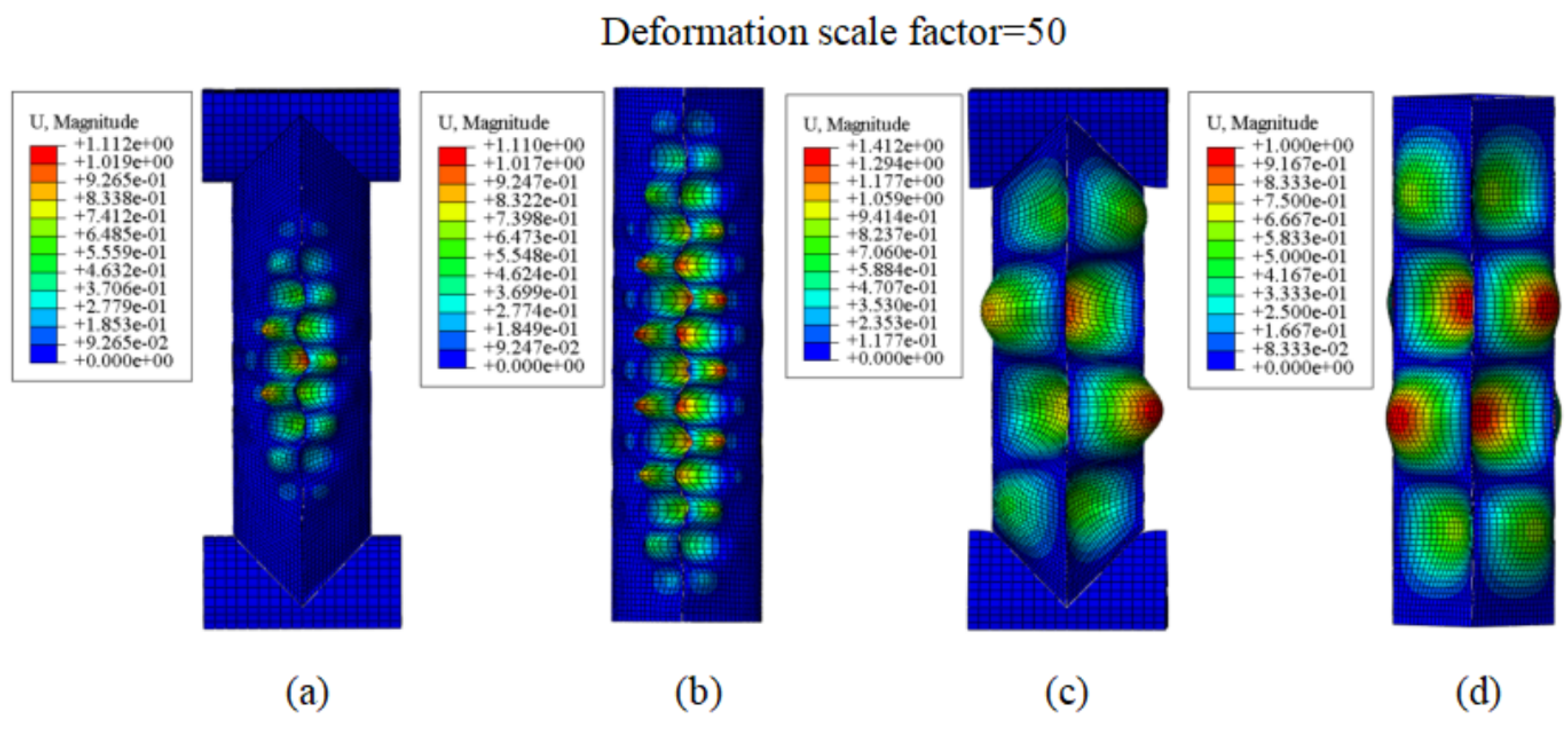
To further investigate this phenomenon, the first-order buckling modes and their corresponding eigenvalues of various columns are summarized in Figure 20 and Figure 21 and Table 9. It can be observed that both OCC and TCC exhibit local buckling concentrated along the crease lines, while the panel surfaces remain stable. In contrast, OSC and TSC experience buckling in the panel regions. The first-order buckling eigenvalues of OCC and TCC are similar and approximately 1075.6% higher than those of the foldable conventional square columns, further demonstrating that the pre-bending of curved surfaces significantly enhances the out-of-plane bending stiffness of the panels. This effectively suppresses panel buckling and contributes to the superior load-bearing capacity of the columns, consistent with the conclusions drawn in Table 8.
Moreover, the eigenvalue of OCC-D is 4% higher than that of TCC-D, indicating that the self-locking geometry of the pillow box may restrict deformation and further delay panel buckling, thereby enhancing the load-bearing performance. This trend aligns well with the peak force and stiffness results.
These findings indicate that, compared with conventional tubular columns, foldable columns based on the pillow box pattern can maintain a significantly higher load-bearing capacity. Notably, the load-to-weight ratio of the OCC-D column is nearly twice that of a comparable square tubular column, with values of 658.9 and 336.3 for OCC-D and TSC-D, respectively.
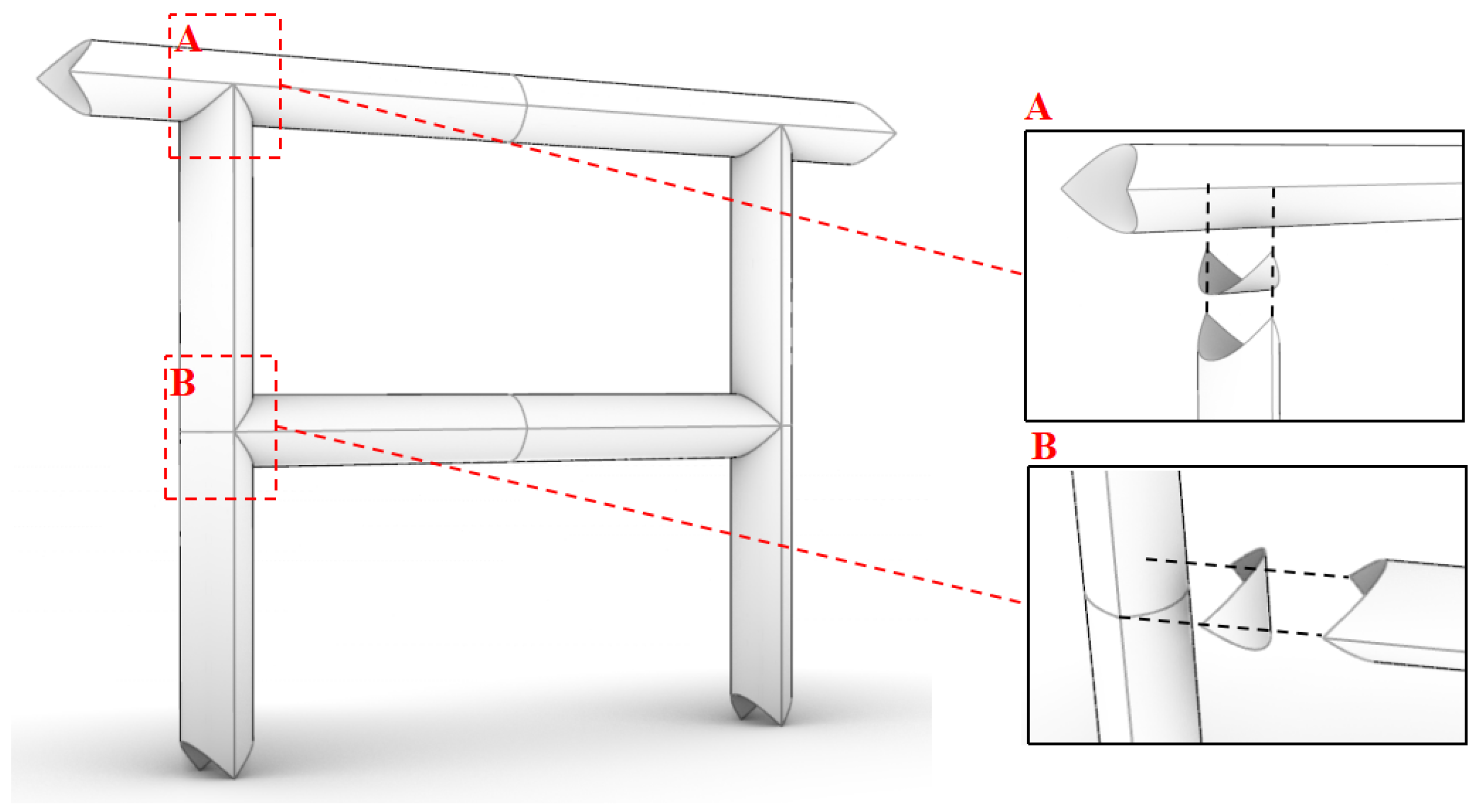
The pillow box configuration serves as a modular structural unit, allowing face-to-face connections between adjacent components. This addresses the challenge of difficult interconnections commonly encountered in conventional pre-bending tubular elements. As illustrated in Figure 22, this modular connectivity not only facilitates rapid assembly but also ensures enhanced structural stability.

6. Conclusions

To enable rapid construction of lightweight architectural structures, a foldable column component based on the pillow box origami configuration was proposed. Two commonly used crease-weakening forms were selected, and their mechanical performance was systematically investigated through crease-folding validation tests, finite element comparison of four types of origami columns (a total of eight samples), and a parametric analysis of geometric crease details. The main conclusions are as follows:
1. Both the “dashed-line” and “slit-hole” crease-weakening strategies can facilitate foldability while preserving the axial load-bearing capacity of the columns.
2. Origami columns employing the “dashed-line” weakening form exhibit superior axial compression performance compared to those using the “slit-hole” form. Specifically, the ultimate load of the OCC-D column is 13.9% higher than that of the OCC-H.
3. The OCC columns outperform their counterparts with straight creases (OSC), tubular curved surfaces (TCC), and conventional square tubes (TSC) in terms of axial load-bearing performance. Notably, the load-to-weight ratio of the OCC-D column reaches 658.9, while that of the TSC-D column is only 336.3.
4. A denser crease arrangement (i.e., higher n) leads to improved load-bearing capacity in OCC-D columns. Meanwhile, the ultimate load and stiffness are maximized when l c = l n .
This study represents the first systematic investigation into the influence of crease-weakening forms on the mechanical behavior of thin-walled deployable origami load-bearing structures. The findings reveal the great potential of such structures for lightweight and rapid architectural construction. Despite the promising results, certain limitations remain. Given the limitation of testing only a single specimen, but considering that the primary objective was to validate the FE modeling of the creases and the good agreement observed between experiment and simulation, this study relies primarily on finite element analysis to conduct a preliminary exploration of crease-weakening effects, with future work planned to expand the experimental scope and further enhance the generality and engineering applicability of the results. In addition, future work could focus on exploring other foldable, high-strength materials, in combination with experimental studies, to further promote the practical application of these structures as large-scale architectural components.

Author Contributions

Q.Z.: Writing—Original draft, Validation, Methodology, Formal analysis. J.M.G.: Conceptualization, Supervision. J.F.: Supervision. All authors have read and agreed to the published version of the manuscript.

Funding

The research presented in the paper was supported by China Scholarship Council (CSC, No. 202306090173).

Data Availability Statement

The original contributions presented in this study are included in the article. Further inquiries can be directed to the corresponding author.

Acknowledgments

The first author acknowledges scholarship support from the China Scholarship Council (CSC, No. 202306090173). The authors would like to thank Ting-Uei Lee for his assistance with the design of the 3D beam–column joints.

Conflicts of Interest

The authors declare that they have no known competing financial interests or personal relationships that could have appeared to influence the work reported in this paper.

References

  1. Huang, Z.; Chen, Z.; Zhu, L.; Ye, L.; Liu, Q. Implementation of parametric modeling to design Miura origami-inspired canopy toward adaptive urban habitat. Archit. Struct. Constr. 2024, 4, 113–122. [Google Scholar] [CrossRef]
  2. Melançon, D.; Bertoldi, K.; Garcia-Mora, C.J.; Hoberman, C.; Gorissen, B. Multistable inflatable origami structures at the metre scale. Nature 2021, 592, 545–550. [Google Scholar] [CrossRef] [PubMed]
  3. Tachi, T. Rigid-Foldable Thick Origami. J. Mech. Des. 2010, 132, 011005. [Google Scholar] [CrossRef]
  4. Ando, K.; Izumi, B.; Shigematsu, M.; Tamai, H.; Matsuo, J.; Mizuta, Y.; Miyata, T.; Sadanobu, J.; Suto, K.; Tachi, T. Lightweight rigidly foldable canopy using composite materials. SN Appl. Sci. 2020, 2, 1994. [Google Scholar] [CrossRef]
  5. Norman, M.; Arjomandi, K. Origami Applications in Structural Engineering: A Look at Temporary Shelters. In Proceedings of the 2nd World Congress on Civil, Structural, and Environmental Engineering (CSEE’17), Barcelona, Spain, 2–4 April 2017; Volume 130, pp. 2371–2452. [Google Scholar]
  6. Acevedo, S. Paper Architecture Inspired in Origami and Emergency Temporary Architecture: Challenges and Potentials in This Implementation. In Proceedings of the 3rd Annual International Conference on Architecture and Civil Engineering (ACE 2015), Singapore, 13–14 April 2015; pp. 1–5. [Google Scholar]
  7. Durney, M.W.; Pendley, A.D. Precision-Folded, High Strength, Fatigue-Resistant Structures and Sheet Therefor. U.S. Patent US8377566B2, 19 February 2013. [Google Scholar]
  8. Marasciuolo, N.; Tommasi, D.D.; Trentadue, F.; Vitucci, G. Tailored multiscale instabilities in a grid metamaterial. Extrem. Mech. Lett. 2025, 75, 102284. [Google Scholar] [CrossRef]
  9. Ghandi, M. Designing Affordable, Portable, and Flexible Shelter for the Homeless and the Refugees. In Proceedings of ECAADe 2018: Computing for a Better Tomorrow; eCAADe and Faculty of Civil Engineering, Architecture and Environmental Engineering, Lodz University of Technology: Łódź, Poland, 2018; Volume 1. [Google Scholar]
  10. Tumbeva, M.; Wang, Y.; Sowar, M.; Dascanio, A.; Thrall, A. Quilt pattern inspired engineering: Efficient manufacturing of shelter topologies. Autom. Constr. 2016, 63, 57–65. [Google Scholar] [CrossRef]
  11. Thrall, A.; Quaglia, C. Accordion shelters: A historical review of origami-like deployable shelters developed by the US military. Eng. Struct. 2014, 59, 686–692. [Google Scholar] [CrossRef]
  12. Martínez-Martín, F.; Thrall, A. Honeycomb core sandwich panels for origami-inspired deployable shelters: Multi-objective optimization for minimum weight and maximum energy efficiency. Eng. Struct. 2014, 69, 158–167. [Google Scholar] [CrossRef]
  13. Lee, T.; Gattas, J. Geometric design and construction of structurally stabilized accordion shelters. J. Mech. Robot. 2016, 8, 031009. [Google Scholar] [CrossRef]
  14. Tepavčević, B.; Stojaković, V.; Mitov, D. Mass Customization of Deployable Origami-based Structures. In Blucher Design Proceedings; Editora Blucher: Porto, Portugal, 2019; pp. 163–170. [Google Scholar] [CrossRef]
  15. Micheletti, A.; Giannetti, I.; Mattei, G.; Alessandro, T. Kinematic and static design of rigid origami structures: Application to modular yoshimura patterns. J. Archit. Eng. 2022, 28, 04022009. [Google Scholar] [CrossRef]
  16. Koschitz, D. Curved-Crease Paperfolding Shell. In Proceedings of the IASS Annual Symposium: Origami Folded Systems, Barcelona, Spain, 7–10 October 2019; pp. 1–8. [Google Scholar]
  17. Martín-Pastor, A.; García-Alvarado, R. Developable Wooden Surfaces for Lightweight Architecture: Bio-Dune Pavilion. In Digital Wood Design: Innovative Technologies Representing Architectural Design; Bianconi, F., Filippucci, M., Eds.; Springer: Berlin/Heidelberg, Germany, 2021; pp. 1481–1500. [Google Scholar]
  18. Fayyad, I. Mapping Rectangles to Cylinders: Waste-Conscious Constructions of Curved Structural Surfaces. Technol. Archit. Des. 2023, 7, 53–66. [Google Scholar] [CrossRef]
  19. Zhu, Y.; Filipov, E.T. Large-scale modular and uniformly thick origami-inspired adaptable and load-carrying structures. Nat. Commun. 2024, 15, 2353. [Google Scholar] [CrossRef]
  20. Nagy, L.; Rhode-Barbarigos, L.; Adriaenssens, S.; Kilian, A. Conceptual design of a single-crease origami-arc inspired movable footbridge structure. Int. J. Space Struct. 2015, 30, 75–84. [Google Scholar] [CrossRef]
  21. Maleczek, R.; Bernhard, M.; Maderebner, R.; Preisinger, C. Fold and Snap–Flatpacking a Wooden Beam. In Proceedings of the IASS 2024 Symposium: Redefining the Art of Structural Design, Zurich, Switzerland, 26–30 August 2024. [Google Scholar]
  22. Woodruff, S.R.; You, Z.; Gattas, J.M. Curved creases redistribute global bending stiffness in corrugations: Theory and experimentation. J. Mech. Mater. Struct. 2020, 15, 215–230. [Google Scholar] [CrossRef]
  23. Lee, M.; Abu-Saleem, M.; Tachi, T.; Gattas, J.M. A Lightweight Building Construction System Using Curved-Crease Origami Blocks. In Proceedings of the International Meeting on Origami in Science, Mathematics and Education (OSME), Melbourne, Australia, 16–18 July 2024. [Google Scholar]
  24. Brancart, S.; Vergauwen, A.; Roovers, K.; den Bremt, D.V.; Laet, L.D.; Temmerman, N.D. Undulatus: Design and Fabrication of a Self-Interlocking Modular Shell Structure Based on Curved-Line Folding. In Proceedings of the IASS Annual Symposia, Amsterdam, The Netherlands, 17–20 August 2015; pp. 1–12. [Google Scholar]
  25. Filz, G.H.; Kumrić, I. Z-snap Pavilion: Advanced Fabrication and Assembly of Self-Locking, Bending Active Modules into a Semi-Double-Layer, shell-like structure. In Proceedings of the IASS Annual Symposia, Hamburg, Germany, 25–28 September 2017; pp. 1–8. [Google Scholar]
  26. Körner, A.; Eshraghi, V.; Zolfaghari, A.; Haghighi, L.A.; Kalantari, M.; Knippers, J. Arch(k)inetic–Curved-Line Folding for Elastic, Adaptive Building Envelopes. In Proceedings of the IASS Annual Symposia, Boston, MA, USA, 16–20 July 2018; pp. 1–8. [Google Scholar]
  27. Bukauskas, A.; Koronaki, A.; Lee, T.-U.; Ott, D.; Al Asali, M.W.; Jalia, A.; Bashford, T.; Gatóo, A.; Newman, J.; Gattas, J.M.; et al. Curved-crease origami face shields for infection control. PLoS ONE 2021, 16, e0245737. [Google Scholar] [CrossRef] [PubMed]
  28. Ma, W.; Liu, X.; Qiu, X.; Zhou, Y.; Liu, Y.; Fu, W.; Guo, X.; Qian, Z.; Du, K.; Cai, J. Comparative folding/unfolding performance of notch-type compliant joints. Case Stud. Constr. Mater. 2023, 18, e01760. [Google Scholar] [CrossRef]
  29. Raducanu, D.; Cojocaru, V.D.; Raducanu, V.A.; Nocivin, A.; Serban, N.; Cinca, I.; Cojocaru, E.M.; Moldovan, L.; Trisca-Rusu, C.; Balkan, I.V. Design and Optimization of a Curved-Crease-Folding Process Applied to a Light Metallic Structure. Processes 2021, 9, 1110. [Google Scholar] [CrossRef]
  30. Ma, J. Thin-Walled Tubes with Pre-Folded Origami Patterns as Energy Absorption Devices. Ph.D. Thesis, University of Oxford, Oxford, UK, 2011. [Google Scholar]
  31. Song, J.; Chen, Y.; Lu, G. Axial crushing of thin-walled structures with origami patterns. Thin-Walled Struct. 2012, 54, 65–71. [Google Scholar] [CrossRef]
  32. Zhang, B.; Men, C.; Kong, Y.; Lv, Z.; Li, C.; Hu, D. Quasi-Static Compression Response and Energy Absorption of CNTF/EP Origami Thin-Walled Tubes. Adv. Mater. Interfaces 2025, 12, 2400826. [Google Scholar] [CrossRef]
  33. Shi, Q.; Shi, X.; Gattas, J.M.; Kitipornchai, S. Folded assembly methods for thin-walled steel structures. Thin-Walled Struct. 2021, 160, 107372. [Google Scholar] [CrossRef]
  34. Ablat, M.A.; Alafaghani, A.; Sun, J.Q.; Qattawi, A. Experimental Evaluation of Tension and Shear Responses of Material Discontinuities in Origami-Based Sheet Metal Bending. J. Manuf. Sci. Eng. 2018, 140, 071016. [Google Scholar] [CrossRef]
  35. Ablat, M.A.; Qattawi, A. Finite Element Analysis of Origami-Based Sheet Metal Folding Process. J. Eng. Mater. Technol. 2018, 140, 031008. [Google Scholar] [CrossRef]
  36. Jeong, D.; Lee, K. Design and analysis of an origami-based three-finger manipulator. Robotica 2018, 36, 261–274. [Google Scholar] [CrossRef]
  37. Bai, Y.; Nardi, D.C.; Zhou, X.; Picón, R.A.; Flórez-López, J. A new comprehensive model of damage for flexural subassemblies prone to fatigue. Comput. Struct. 2021, 256, 106639. [Google Scholar] [CrossRef]
  38. Wagner, M.A.; Huang, J.-L.; Okle, P.; Paik, J.; Spolenak, R. Hinges for origami-inspired structures by multimaterial additive manufacturing. Mater. Des. 2020, 191, 108643. [Google Scholar] [CrossRef]
  39. Moshtaghzadeh, M. Prediction of fatigue life of a flexible foldable origami antenna with Kresling pattern. Eng. Struct. 2022, 251, 113399. [Google Scholar] [CrossRef]
  40. Moshtaghzadeh, M.; Bakhtiari, A.; Izadpanahi, E.; Mardanpour, P. Artificial Neural Network for the prediction of fatigue life of a flexible foldable origami antenna with Kresling pattern. Thin-Walled Struct. 2022, 174, 109160. [Google Scholar] [CrossRef]
  41. Ablat, M.A.; Qattawi, A. Investigating the design and process parameters of folded perforated sheet metal. Int. J. Adv. Manuf. Technol. 2019, 102, 615–633. [Google Scholar] [CrossRef]
  42. Shi, Q.; Heitzmann, M.T.; Gattas, J.M. Nonlinear rotational stiffness and clash prevention in perforated steel fold lines. Eng. Struct. 2020, 209, 110218. [Google Scholar] [CrossRef]
  43. Nasrollahi, V.; Arezoo, B. Prediction of springback in sheet metal components with holes on the bending area, using experiments, finite element and neural networks. Mater. Des. 2011, 32, 695–705. [Google Scholar] [CrossRef]
  44. Nikhare, C.P.; Kotkunde, N.; Singh, S.K. Effect of material discontinuity on springback in sheet metal bending. J. Mater. Eng. Perform. 2013, 22, 3445–3452. [Google Scholar] [CrossRef]
  45. Hwang, H.-Y. Effects of perforated crease line design on mechanical behaviors of origami structures. Int. J. Solids Struct. 2021, 230–231, 111158. [Google Scholar] [CrossRef]
  46. Chen, Y.; Shi, P.; Bai, Y.; Li, J.; Feng, J.; Sareh, P. Engineered origami crease perforations for optimal mechanical performance and fatigue life. Thin-Walled Struct. 2024, 185, 110572. [Google Scholar] [CrossRef]
  47. Mitani, J. Pillow Box Design. arXiv 2024, arXiv:2410.17593. [Google Scholar] [CrossRef]
  48. Lee, T.U.; You, Z.; Gattas, J.M. Elastica Surface Generation of Curved-Crease Origami. Int. J. Solids Struct. 2018, 136–137, 13–27. [Google Scholar] [CrossRef]
  49. Howe, D.V.; Dimeska, A. Polypropylene, Isotactic. In Polymer Data Handbook; Mark, J.E., Ed.; Oxford University Press: Oxford, UK, 2009; pp. 971–978. [Google Scholar]
  50. Weerasekara, L.; Mallikarachchi, C. Effect of Crease Curvature on Bending Stiffness in Curved Crease Origami. In Proceedings of the 2024 Moratuwa Engineering Research Conference (MERCon), Moratuwa, Sri Lanka, 8–10 August 2024; IEEE: New York, NY, USA, 2024; pp. 1–6. [Google Scholar] [CrossRef]
  51. Zhang, Q.; Zhou, Y.; Zhou, Y.; Kim, S.; Feng, J.; Cai, J. Numerical analysis on buckling-control of slender tube inspired by origami. Int. J. Non-Linear Mech. 2025, 171, 105025. [Google Scholar] [CrossRef]
  52. Ma, J.; You, Z. Energy absorption of thin-walled beams with a pre-folded origami pattern. Thin-Walled Struct. 2013, 73, 198–206. [Google Scholar] [CrossRef]
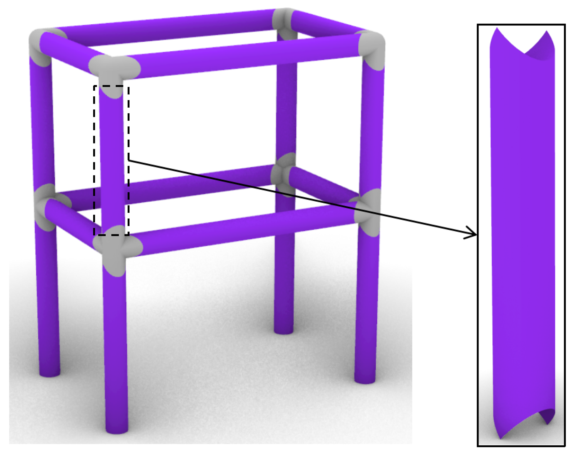
Figure 1. Frame structure assembled from pillow box elements.
Applsci 15 10756 g001
Figure 2. (a) OCC (b) OSC.
Applsci 15 10756 g002
Figure 3. (a) TCC (b) TSC.
Applsci 15 10756 g003
Figure 4. Crease-weakening strategies: (a) dashed-line type and (b) slit-hole type.
Applsci 15 10756 g004
Figure 5. Specimen fabrication: (a) dashed-line type and (b) slit-hole type.
Applsci 15 10756 g005
Figure 6. (a) Test setup, (b) end caps, and (c) numerical model.
Applsci 15 10756 g006
Figure 7. Constitutive relationship curve of PP.
Applsci 15 10756 g007
Figure 8. Axial compression deformation process of PPC1T1D. (a) Experimental results; (b) finite element predictions.
Applsci 15 10756 g008
Figure 9. Axial compression deformation process of PPC1T1H. (a) Experimental results; (b) finite element predictions.
Applsci 15 10756 g009
Figure 10. Comparison of load–displacement curves between experimental and numerical results; (a) PPC1T1D and (b) PPC1T1H.
Applsci 15 10756 g010
Figure 11. (a) Refined modeling of creases and (b) finite element mesh generation.
Applsci 15 10756 g011
Figure 12. Failure modes of the dashed-line specimens, shown at three stages from left to right: initial configuration, peak load, and final deformation stage. (a) OCC-D; (b) OSC-D; (c) TCC-D; (d) TSC-D.
Applsci 15 10756 g012
Figure 13. Failure mode of the slit-hole specimens, shown at three stages from left to right: initial configuration, peak load, and final deformation stage. (a) OCC-H; (b) OSC-H; (c) TCC-H; (d) TSC-H.
Applsci 15 10756 g013
Figure 14. Load–displacement curves (a) “dashed-line” columns and (b) “slit-hole” columns.
Applsci 15 10756 g014
Figure 15. Failure mode and stress distribution: (a) OCC1, (b) OCC4, and (c) OCC5.
Applsci 15 10756 g015
Figure 16. Load–displacement response of OCC1, OCC4, and OCC5.
Applsci 15 10756 g016
Figure 17. Failure mode and stress distribution: (a) OCC1, (b) OCC2, and (c) OCC3.
Applsci 15 10756 g017
Figure 18. Load–displacement response of OCC1, OCC2, and OCC3.
Applsci 15 10756 g018
Figure 19. The first buckling mode of (a) OCC3, (b) OCC1, and (c) OCC2.
Applsci 15 10756 g019
Figure 20. The first buckling mode of (a) OCC-D, (b) TCC-D, (c) OSC-D, and (d) TSC-D.
Applsci 15 10756 g020
Figure 21. The first buckling mode of (a) OCC-H, (b) TCC-H, (c) OSC-H, and (d) TSC-H.
Applsci 15 10756 g021
Figure 22. Schematic illustration of the connection between pillow box components.
Applsci 15 10756 g022
Table 1. Comparison between FEA and experimental results.
MetricPPC1T1DPPC1T1H
Peak Force (kN)
   Test0.760.66
   FEA0.770.67
   Difference (%)1.321.52
Stiffness (kN/mm)
   Test1.040.98
   FEA1.071.00
   Difference (%)2.882.04
Table 2. Variable geometric parameters of specimens.
Specimenh/mm a r /mm a 0 (°)
OCC-D126\\
OSC-D138\\
TCC-D126\\
TSC-D138\\
OCC-H126590
OSC-H138590
TCC-H126590
TSC-H138590
Table 3. Mechanical properties of OCCD and OCCH.
SamplePeak Force (kN)Stiffness (kN/mm)
OCC-D0.8170.74
OCC-H0.7200.76
Table 4. Structural parameters of OCC1–OCC5.
Sample ϕ l c (mm) l h (mm) l h / l c n
OCC1 (OCC-D)0.610151.5018
OCC20.6691.5030
OCC30.620301.509
OCC40.415100.6718
OCC50.512.512.51.0018
Note: l c and l h denote the lengths of the crease-connected segment and crease-open segment, respectively.
Table 5. Summary of peak load and stiffness for OCC columns with different values of ϕ .
Sample ϕ Peak Load (kN)Stiffness (kN/mm)
OCC10.60.820.74
OCC40.40.850.74
OCC50.50.870.78
Table 6. Summary of peak load and stiffness for OCC columns with different values of n.
SamplenPeak Load (kN)Stiffness (kN/mm)
OCC1180.820.74
OCC2360.900.69
OCC390.750.78
Table 7. Summary of the first-order buckling eigenvalues of OCC1, OCC2, and OCC3.
SampleOCC3OCC1OCC2
Eigenvalue779.01086.31175.8
Table 8. Summary of mechanical properties.
SamplePeak Force (kN)Stiffness (kN/mm)
OCC-D0.8170.74
TCC-D0.7280.64
OSC-D0.4110.27
TSC-D0.4170.34
OCC-H0.7200.76
TCC-H0.6560.73
OSC-H0.2600.41
TSC-H0.2740.35
Table 9. Summary of the first-order buckling eigenvalues of different origami columns.
SampleOCC-DTCC-DOSC-DTSC-DOCC-HTCC-HOSC-HTSC-H
Eigenvalue1086.31044.593.892.4810.4760.257.786.7
Disclaimer/Publisher’s Note: The statements, opinions and data contained in all publications are solely those of the individual author(s) and contributor(s) and not of MDPI and/or the editor(s). MDPI and/or the editor(s) disclaim responsibility for any injury to people or property resulting from any ideas, methods, instructions or products referred to in the content.