Article

Evaluation and Correction of Systematic Motion Errors in a Compact Three-Wheeled Omnidirectional Platform Based on Servomotors

Automation and Robotics Laboratory, Universitat de Lleida, 25001 Lleida, Spain
*
Author to whom correspondence should be addressed.
Appl. Sci. 2025, 15(19), 10700; https://doi.org/10.3390/app151910700
Submission received: 4 September 2025 / Revised: 30 September 2025 / Accepted: 1 October 2025 / Published: 3 October 2025
(This article belongs to the Special Issue Recent Advances in Mechatronic and Robotic Systems—2nd Edition)

Abstract

This paper evaluates and corrects systematic odometry errors in a compact omnidirectional mobile platform equipped with three omni-wheels driven by digital servomotors featuring velocity control capabilities. Compared to differential-drive platforms, omnidirectional platforms offer the significant advantage of being able to translate in any direction while rotating simultaneously. The motion capabilities of the platform have been experimentally evaluated, and its systematic motion errors analyzed and corrected. The final motion capabilities achieved confirm that a basic three-wheeled omnidirectional platform driven by servomotors is suitable for use as a testbench for control algorithms and trajectory-tracking experiments.

1. Introduction

Omnidirectional motion systems provide enhanced maneuverability by enabling simultaneous rotation and translation in any direction. This versatility has fostered the use of omnidirectional platforms in a wide range of practical applications, including nuclear site inspection [1], ferromagnetic structure inspection [2], industrial transportation [3], irregular terrain applications [4] and assistive walking devices [5]. Omnidirectional mobility can be achieved with different configurations [6,7,8], such as symmetric layouts [9,10], three-omni-wheeled platforms [11], and Mecanum wheel systems [12,13,14]. Further research in this field has also explored alternative wheel arrangements, including platforms equipped with six wheels [15] and even eight wheels [16].
Accurate odometry is essential for estimating position over time [17,18]. However, odometry is inherently susceptible to drift caused by factors such as incorrect wheelbase length, unequal wheel diameters, wheel misalignment, and wheel slippage, among others. These errors are typically classified into systematic [19] and non-systematic errors [20]. Systematic errors are predictable, repeatable and usually consistent over time, whereas non-systematic errors are unpredictable and usually arise from external disturbances during operation. Both types of errors can lead the robot to deviate from the intended trajectory. For this reason, identifying and calibrating systematic motion errors is critical to improve long-term navigation accuracy.
This paper presents the design and implementation of a compact omnidirectional mobile platform developed as a testbench for control algorithms and trajectory-tracking experiments. The platform has been analyzed to evaluate and correct systematic odometry errors to ensure accurate and reliable motion performances.
The reference used to evaluate and correct systematic odometry errors is the proposal of Borenstein et al. [21], featuring the University of Michigan Benchmark (UMBmark), a simple effective method in which a differential-drive robot drives a square path in clockwise and counterclockwise directions to isolate systematic odometry errors. The method identifies two main error sources: incorrect wheelbase length and unequal wheel diameters. Over the years, Lee et al. [22] improved the UMBmark procedure by deriving a new calibration equation that accounts for the coupled effects of unequal wheel diameters and wheelbase errors. Wang et al. [23] adapted the UMBmark test to differential-drive robots with four wheels by introducing a new type C error to analyze speed differences between ipsilateral wheels. In this work, the original UMBmark methodology has been evaluated and adapted for its application to a three-wheeled omnidirectional motion system.
In scientific literature, there are a huge number of studies focusing on systematic odometry calibration. Sousa et al. [24] published a review article summarizing the evolution of calibration methods developed for ground mobile robots.
Closely related to the proposal of this work, some approaches perform odometry calibration only once prior to robot operation. Tomasi et al. [25] proposed a novel odometry calibration method for differential robot platforms that relies solely on rotational movements. Unlike traditional approaches, which require linear displacement over a large area, their method enables effective calibration in a confined space, while achieving accuracy comparable to classical techniques. Bostani et al. [26] introduced a simple method to measure and correct odometry errors in differential-drive robots. Their approach focuses on common issues such as unequal wheel diameters and wheelbase errors, using precise measurements and implementing corrections through the control software of the robot. Ivanjko et al. [27] proposed a simplified calibration method based on straight-line movements and 180-degree turns, providing a more practical and space-efficient alternative to traditional calibration paths. Jung et al. [28] proposed a new calibration scheme whose calibration equations have fewer approximation errors and account for the interaction between wheel diameter and wheelbase errors, resulting in more accurate odometry correction.
Other research has focused on methods that perform odometry calibration while the robot is in motion. Antonelli et al. [29] formulated odometry calibration as a linear estimation problem, using the least-squares method over multiple calibration runs with different trajectories. Mondal et al. [30] proposed an odometry calibration method based on Terminal Iterative Learning Control (TILC), which allows systematic errors to be corrected using arbitrary trajectories rather than predefined ones. De Giorgi et al. [31] developed an online odometry calibration method for differential-drive robots that handles slippage using common onboard sensors like encoders, gyroscopes, and IMUs, achieving high accuracy even under low-traction conditions.
Additionally, odometry calibration can be improved by combining different sensing devices. Censi et al. [32] proposed a simultaneous calibration method for both odometry and sensor parameters in differential-drive robots, using onboard sensors and formulating the problem as a maximum-likelihood estimation, without requiring specific trajectories or external equipment. Cantelli et al. [33] proposed an automatic calibration method using an extended Kalman filter to estimate key kinematic parameters and magnetometer offset, improving the localization of a tracked mobile robot for outdoor use. Nevertheless, the compact omnidirectional platform used in this work does not include additional sensing devices to evaluate the motion of the platform.
The specific problem of the calibration of systematic motion errors in three-wheeled omnidirectional mobile platforms has been explored less than differential-drive platforms. In this case, the additional degrees of freedom present in omnidirectional systems make the estimation process significantly more challenging. In this direction, Maddahi et al. [34] proposed a systematic calibration method for an omnidirectional platform. The method introduced two correction indices, a lateral correction matrix and a longitudinal scale factor, into the kinematic model to compensate for systematic errors in a three-wheeled omnidirectional robot. Lin et al. [35] developed a complete kinematic model of a three-wheeled omnidirectional robot and applied a multiple linear regression technique based on the least-squares method to experimental data in order to estimate the optimal kinematic parameters. Savaee et al. [36] introduced a calibration method for three-wheeled omnidirectional robots that reduces systematic odometry errors by optimizing Effective Kinematic Parameters (EKPs). These parameters combine wheel radius, wheel orientation, and the distance from the center of the robot to each wheel into a corrected Jacobian matrix, obtained through test-based trajectory error minimization. Palacín et al. [37] used a genetic algorithm to search for the optimal inverse kinematic matrix that minimizes odometry error over a set of complex maneuvers, yielding an average improvement of over 80% in position accuracy. Sousa et al. [38] proposed an optimization-based method that treats odometry calibration in a unified way for different drive types by using an iterative optimizer (resilient backpropagation) to fit the kinematics parameters of the robot using only the measured trajectory data. More recently, Palacín et al. [39] developed a non-parametric odometry calibration method using a genetic algorithm (GA) to optimize the inverse kinematic (IK) matrix of a three-wheeled omnidirectional robot to minimize the position error registered in a set of calibration trajectories.

New Contribution

Motivated by the contributions discussed above, this work presents the design and implementation of a compact three-wheeled omnidirectional mobile platform based on digital servomotors. The main contribution of this study is the evaluation and correction of systematic odometry errors to enable the use of the platform as a testbench for control algorithms and trajectory-tracking experiments. The calibration methods assessed for systematic odometry errors include the UMBmark procedure [21] used as a baseline reference, adapted for a three-wheeled omnidirectional configuration, and two direct calibration techniques for correcting rotational [25] and straight-line [27] displacement errors.

2. Materials and Methods

The materials and methods used in this paper are the TRIA-BOT omnidirectional mobile platform and the UMBmark procedure.

2.1. TRIA-BOT Omnidirectional Platform

The TRIA-BOT platform is a compact omnidirectional mobile robot with a motion system based on three omni-wheels, each driven by digital servomotors with velocity control capabilities. The TRIA-BOT platform summarizes the experience of the research team with three-wheeled omnidirectional platforms [40]. TRIA-BOT has been specifically designed to serve as a testbench for control algorithms and for trajectory-tracking experiments. Figure 1 shows two images of the TRIA-BOT mobile platform, highlighting its main mechanical components: the three omnidirectional wheels and a 3D-printed base structure.
Figure 2 details the main electrical and electronic parts of the TRIA-BOT platform: three digital servomotors, a power bank battery, and the platform controller. The movement of the mobile platform is controlled through motion commands interpreted and executed by the controller.

2.1.1. Omnidirectional Wheels

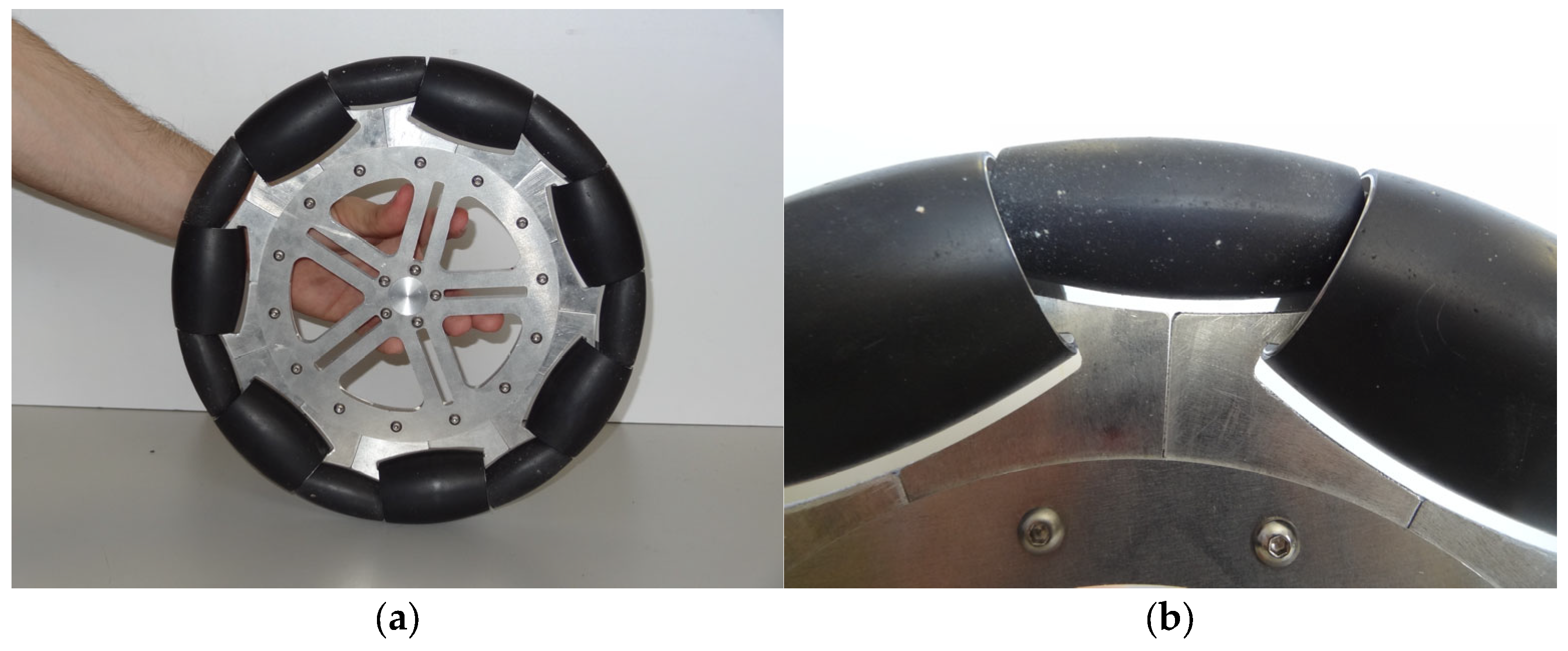
Figure 3 shows the omnidirectional wheel used in the TRIA-BOT platform. This wheel is designed with alternating passive rollers of different sizes and shapes, enabling the wheel to rotate freely while also allowing lateral displacement relative to the direction of wheel rotation [40]. Each wheel consists of seven passive rollers of two different types, whose axes are positioned tangentially to the main circumference of the wheel. The bracket design of the rollers allows the smaller rollers to be partially embedded within the larger ones, effectively reducing the inter-roller gap (2.5 mm). The free rollers on the omnidirectional wheels are covered with a 1 mm thick layer of hard rubber. As a summary, the fabrication tolerances of the different pieces of the wheels combined with the effect of the hard rubber in contact with the floor defines a wheel diameter CAD design of 0.29902 m. More information about this wheel design can be found in [40].

2.1.2. Digital Servomotors

The TRIA-BOT drives the three omnidirectional wheels with three Dynamixel XM540-W270-T digital servomotors (ROBOTIS, Seoul, Korea), categorized as mid-level performance actuators. Each servomotor is powered by a 32-bit ARM Cortex-M3 microcontroller operating at 72 MHz and incorporates an integrated PID control algorithm for both position and velocity regulation. The servomotor features a contactless absolute encoder with 12-bit resolution, enabling full 360° position sensing with a minimum positional increment of 0.088°.
Communication with the digital servomotor is handled via a half-duplex UART (Universal Asynchronous Receiver–Transmitter) protocol, using a single wire for both transmission and reception. Data exchange is performed through 8-bit or 16-bit registers, allowing access to various feedback parameters such as position, velocity, current, trajectory, and temperature, among others. The servomotors can be powered with a 12 V supply, delivering a stall torque of 10.6 Nm at 4.4 A, and achieving a no-load speed of 30 rpm.

2.1.3. The 3D-Printed Platform Base

The base of the omnidirectional platform is manufactured as a single, large piece using a Creality S5 3D printer, with slicing performed in Cura 5.8.1. Figure 4 shows a snapshot of the 3D printing process of the platform base. The piece was fabricated using polylactic acid (PLA), a commonly used thermoplastic for 3D printing and prototyping. The initial plan was to validate the geometry and functionality of the base using a PLA prototype, with the intention of later switching to a more robust engineering thermoplastic. However, the mechanical performance achieved with PLA satisfied the design requirements.

2.1.4. Power Bank

The TRIA-BOT platform is designed to be powered by a 20,000 mAh power bank with a maximum output power of 65 W (Baseus, Shenzhen, China). This power bank provides 12 V to the digital servomotors by using a PD (Power Delivery) trigger module. This module establishes the required negotiation with the power bank to enable 12 V output instead of the default 5 V through one of its USB ports. In this configuration, the power bank can deliver up to 3 A at 12 V.

2.1.5. Platform Controller

The platform controller is a custom electronic board developed by the research team to serve as the main control unit for managing the three servomotors of the platform. This electronic board is based on the STM32F405RGT6 microcontroller, which features a high-performance ARM Cortex-M4 core operating at 168 MHz. The platform controller is responsible for receiving motion commands and generating the corresponding low-level control signals interpretable by the servomotors. Additionally, the platform controller implements continuous acquisition of servomotor feedback parameters for testing and evaluation purposes.
The electronic board is powered through a 12 V power input that supplies power to both the microcontroller and the three servomotors. The electronic board includes USB-to-serial communication for future integration with an onboard computer, and an additional Bluetooth module (HM-10) that enables wireless data exchange between the platform controller and an external computer.

2.1.6. Motion Commands

The omnidirectional platform is designed to natively receive motion commands via USB–serial or Bluetooth–serial communication from an external computer or device controller. The motion commands accepted by the platform controller are as follows:
  • General time–motion command. Represented as M ( v ,   α ,   ω ,   t ) , where v (in m/s) is the linear velocity of the omnidirectional platform, α (in degrees) is the angular orientation of the displacement, ω (in rad/s) is the angular velocity of rotation with respect to the center of the platform, and t (in s) is the duration for which the command is executed by the platform.
  • Rotation command. Represented as R ( β ,   ω R ) , where β (in degrees) defines the rotation angle, and ω R (in rad/s) specifies the angular velocity of the platform during rotation.
The platform controller estimates the required rotational velocity for each of the three individual servomotors to execute the desired motion. The servomotors operate using low-level commands that define the target rotational velocity in revolutions per minute (rev/min), along with other control parameters.

2.2. Reference UMBmark Calibration Procedure

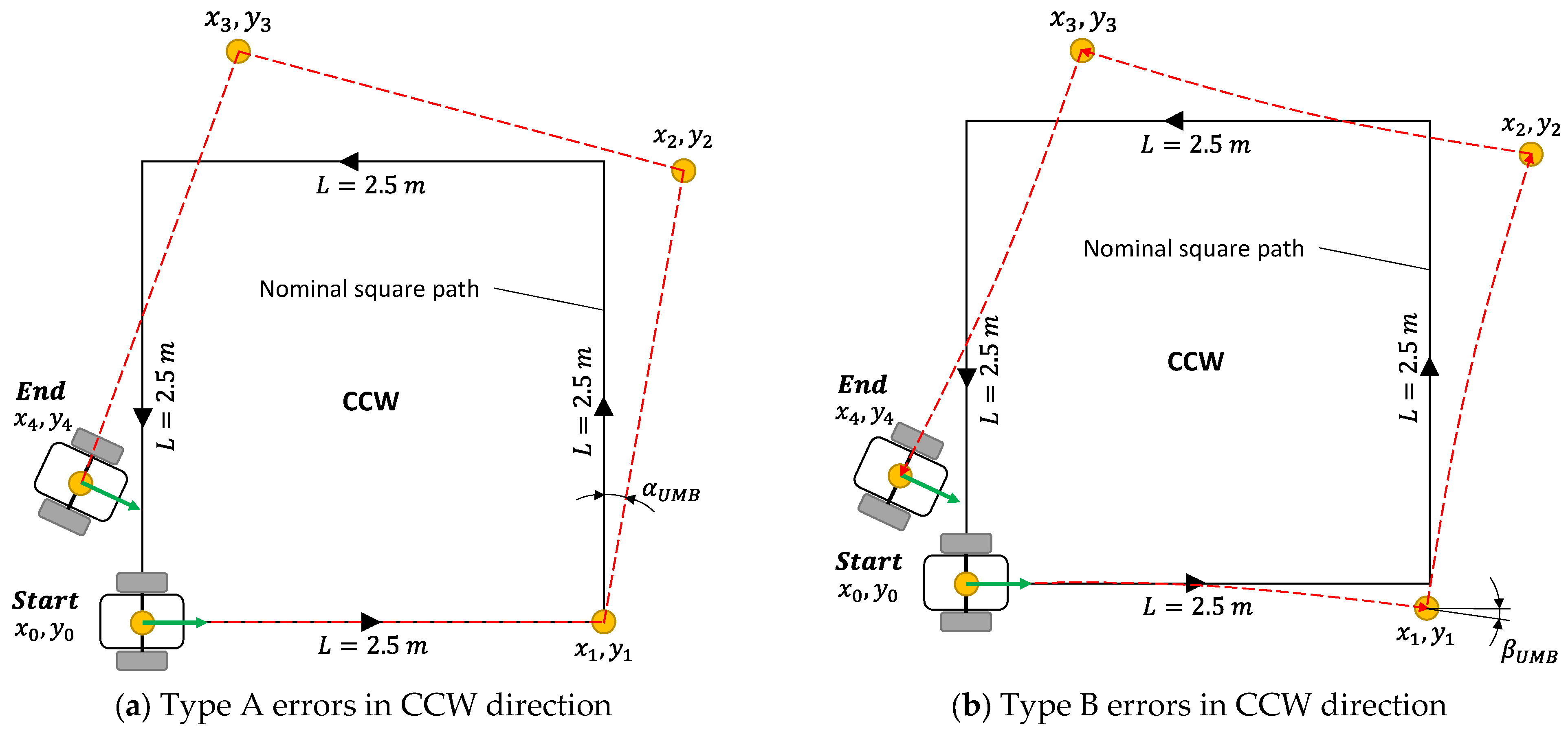
The University of Michigan Benchmark (UMBmark) [21] is a systematic procedure designed to evaluate and calibrate the odometry accuracy of differential-drive robots. This method involves placing a differential-drive robot on a flat test surface to execute a bidirectional square path experiment. This experiment is designed to evaluate two types of systematic orientation errors, known as Type A and Type B errors. Type A errors are assumed to occur only during the pure rotational motions and are attributed to inaccuracies in the wheelbase length, and Type B errors are assumed to occur only during straight-line motions and are caused by unequal wheel diameters.

2.2.1. Reference Bidirectional Square Path for Differential-Drive Platforms

The bidirectional square path trajectory used in the UMBmark to evaluate the Type A and Type B systematic errors consists of a counterclockwise (CCW) and a clockwise (CW) trajectory. Figure 5 illustrates the CCW bidirectional square path trajectory in which a differential-drive platform moves forward a fixed distance and then performs a 90° rotation, repeating this pattern to complete a square path and return to its starting point. During each 90° turn at the corners of the square, small rotational errors (denoted by angle ( α ) ) may cause the platform to either overshoot or undershoot the intended angle; these are classified as Type A errors. Similarly, during straight-line motion, slight angular deviations (denoted by angle ( β ) ) can cause the robot to deviate of the intended path, resulting in Type B errors. As a result, after completing the full square path, the final position and orientation of the robot may differ from its initial position and orientation. The CW trajectory follows the same logic but uses −90° rotations at each corner.

2.2.2. Calibration Parameters for a Differential-Drive Platform

As described before, the UMBmark procedure is used to identify and correct two types of systematic odometry errors in differential-drive platforms. On one hand, Type A errors occur during pure rotational motions and are primarily caused by an inaccurate estimate of the wheelbase length (b), which is the distance between the contact points of the two drive wheels. These errors are identified by calculating the rotation error angle ( α U M B ) , as shown in Figure 5a. Equation (1) (Equation 4.24a in [21]) calculates the rotation error angle ( α x ) and Equation (2) (Equation 4.24b in [21]) calculates the rotation error angle ( α y ) :
α x = x c . g . , C W + x c . g . , C C W 4 L · 180 ° π
α y = y c . g . , C W y c . g . , C C W 4 L · 180 ° π
where x c . g . , C W and x c . g . , C C W represent the average error in the x-direction across multiple runs in CW and CCW directions, respectively. y c . g . , C W and y c . g . , C C W represent the average error in the y-direction across multiple runs in CW and CCW directions, respectively. The representative value of the rotation error angle ( α U M B ) is obtained using Equation (3):
α U M B = α x + α y 2
Since the wheelbase (b) is inversely proportional to the actual rotation achieved, the corrected value of the wheelbase can be obtained using the proportional relationship defined by Equation (4) (Equation 4.26 in [21]):
b a c t u a l = 90 ° 90 ° α U M B · b n o m i n a l
where b n o m i n a l refers to the theoretical wheelbase length, and b a c t u a l represents the calibrated wheelbase length through the UMBmark procedure.
On the other hand, Type B errors occur during straight-line motion and are caused by differences in the diameters of the two wheels. These discrepancies cause the robot to follow a curved path instead of a straight-line trajectory. The resulting deviation is quantified by an orientation error angle ( β U M B ) , as illustrated in Figure 5b. Equation (5) (Equation 4.20a in [21]) calculates the orientation error angle ( β x ) and Equation (6) (Equation 4.20b in [21]) calculates the orientation error angle ( β y ) :
β x = x c . g . , C W x c . g . , C C W 4 L · 180 ° π
β y = y c . g . , C W + y c . g . , C C W 4 L · 180 ° π
The values of β x and β y yield similar results. In this work, a representative value of the orientation error angle ( β U M B ) is obtained using Equation (7):
β U M B = β x + β y 2
Based on this deviation, the radius of curvature ( R ) of the unintended arc is determined using Equation (8) (Equation 4.21 in [21]):
R = L / 2 sin β U M B / 2
where L is the forward distance travelled during the straight-line motion. From the radius of curvature ( R ) , the ratio between the two wheel diameters ( E d ) is computed using Equation (9) (Equation 4.22 in [21]):
E d = D R D L = R + b n o m i n a l / 2 R b n o m i n a l / 2
where D L and D R are the corrected diameters of the left and right wheels. Then, the corrected wheel diameters are obtained from the theoretical wheel diameter ( D a ) by applying Equation (10) (Equation 4.29 in [21]) and Equation (11) (Equation 4.30 in [21]):
D L = 2 E d + 1 D a
D R = 2 ( 1 / E d ) + 1 D a

2.2.3. Calibration Parameters for a Three-Wheeled Omnidirectional Platform

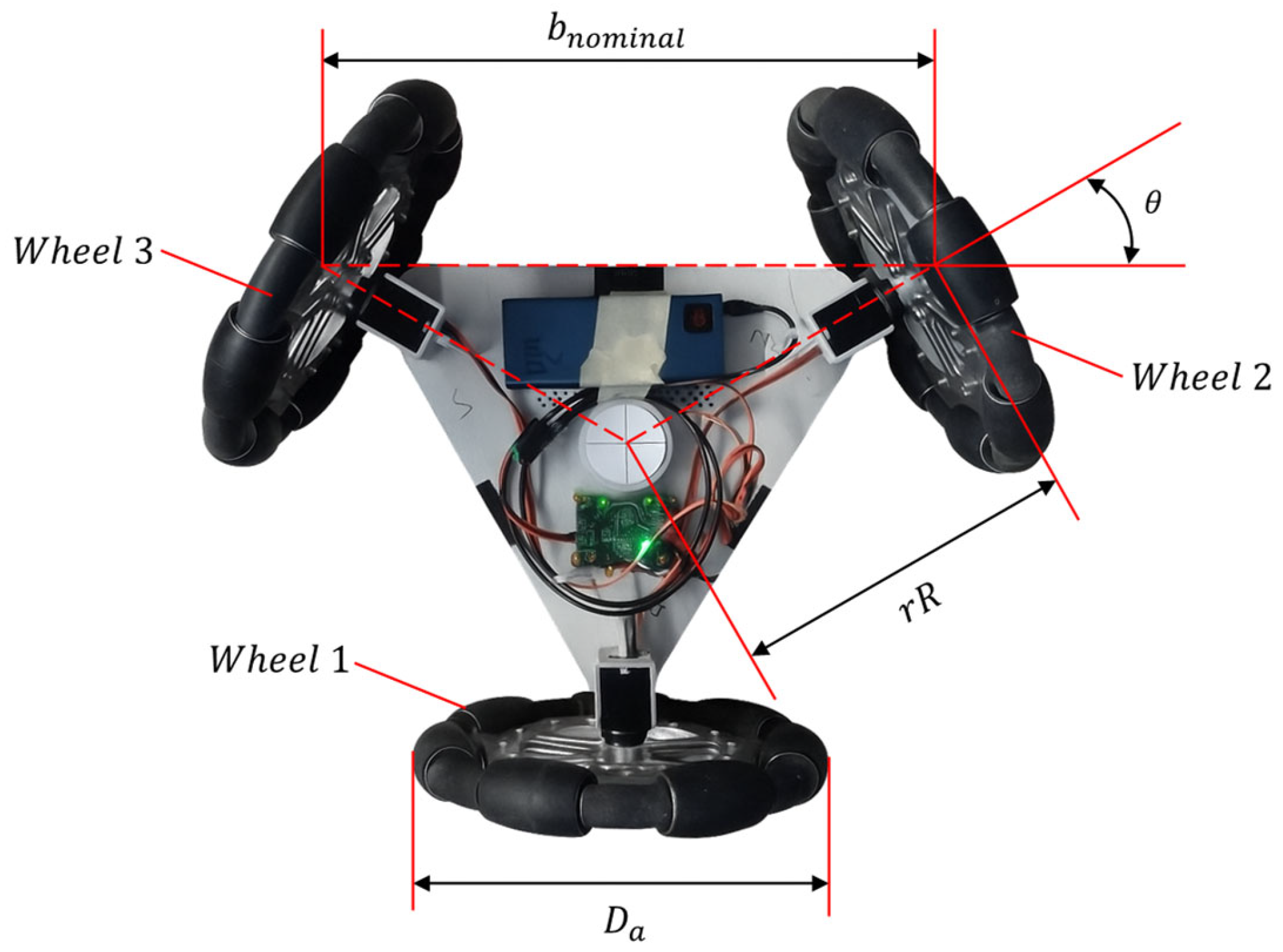
Figure 6 represents the representation of the UMBmark parameters adapted for the case of a three-wheeled omnidirectional platform. The results obtained with this procedure will be used as a baseline calibration reference. The theoretical wheelbase length of the platform (parameter b n o m i n a l ) is calculated using Equation (12):
b n o m i n a l = 2 · cos θ · r R
where θ defines the angular distribution of the wheels, r R is the theoretical radius of the omnidirectional platform, and D a is the theoretical diameter of the omnidirectional wheels. The theoretical values of these parameters are θ = 30 ° , r R = 0.23425 m and D a = 0.29902 m.

2.2.4. Bidirectional Square Paths for a Three-Wheeled Omnidirectional Platform

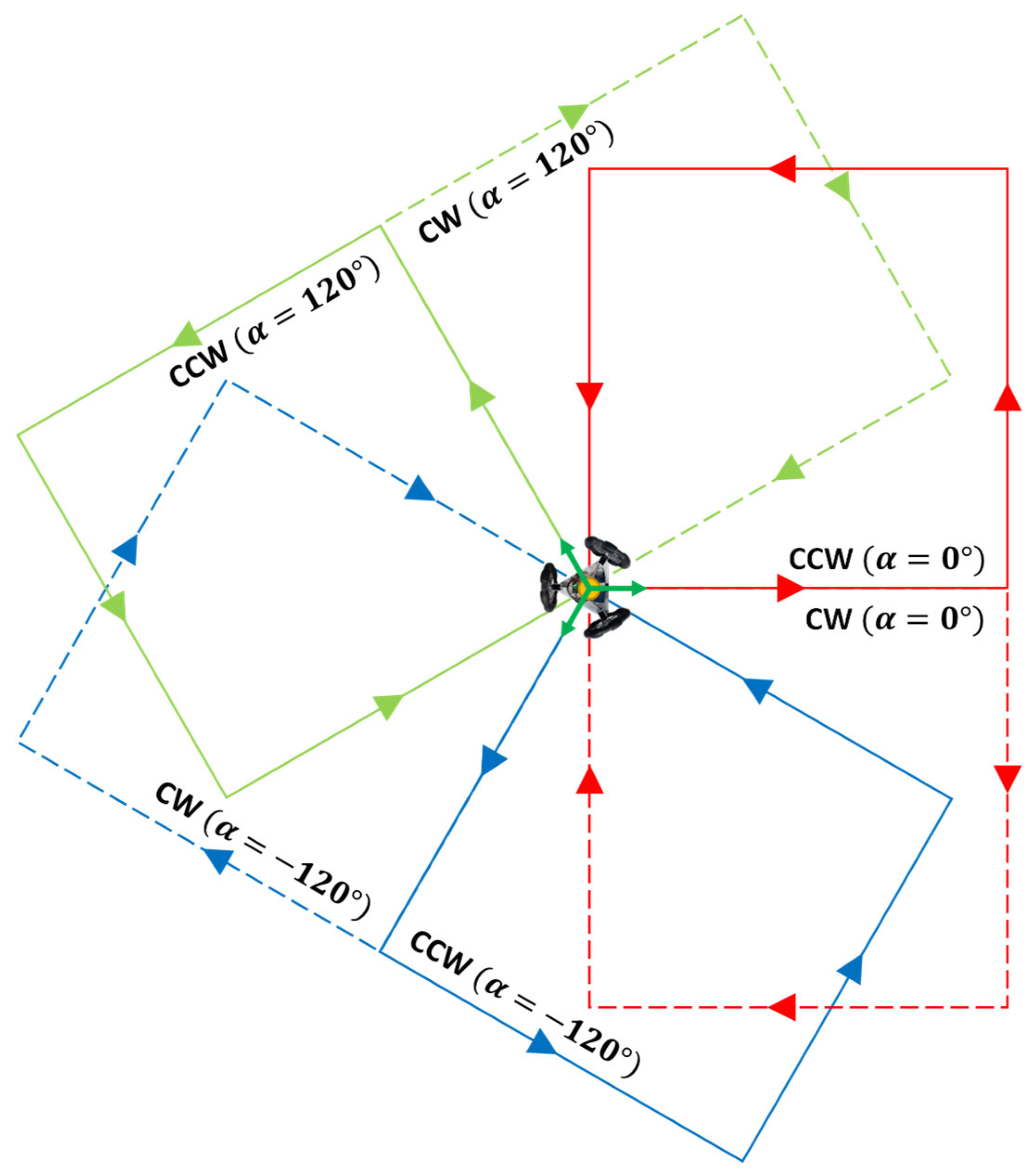
The application of UMBmark with a three-wheeled omnidirectional platform requires the realization of the trajectory experiments in each pair of wheels of the platform. This is because the motion of the omnidirectional platform can be interpreted as the superposition of the displacement of three differential-drive platforms using omnidirectional wheels. Figure 7 details all the trajectories required by the UMBmark applied to the three-wheeled omnidirectional platform.

2.2.5. UMBmark Trajectory Experiment

As a reference, Figure 8 shows the reproduction of the square path experiment of the three-wheeled omnidirectional platform in the case of the CW direction ( α = 0 ° ) . The figure shows multiple captures of the platform at different time samples. Figure 8 shows that the final position and orientation of the platform do not coincide with its starting position and orientation, revealing the existence of systematic errors. These motion experiments have been executed in an open loop, without any external supervision.

2.2.6. UMBmark Trajectory Results

As illustrated in Figure 7, the bidirectional square path experiment was carried out in three different orientations for a three-wheeled omnidirectional platform: 0° degrees, 120° degrees, and −120° degrees. For each orientation, the robot executed the square path experiment five times in both CW and CCW directions. All UMBmark trajectory experiments were conducted with a forward displacement distance (L) of 2.5 m, using a linear velocity of 0.2 m/s during the straight-line trajectory and a constant angular velocity of 0.6 rad/s during the rotational movements because these are the nominal parameters defined for the platform.
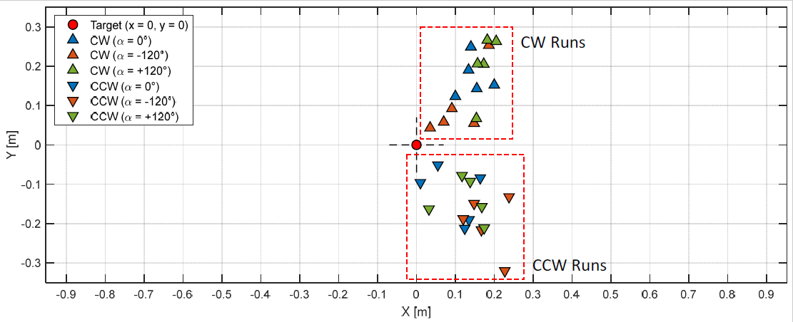
Figure 9 presents a summary of the relative final positions obtained from all the experiments, performed across the three orientations and in both CW and CCW directions (Figure 7). The results clearly show that the final position of the robot deviates from the intended target point, indicating the presence of systematic motion errors. Based on the trajectory results presented in Figure 9, a single numerical value was calculated to quantify the systematic motion errors. Table 1 shows the results of the center of gravity of the final positions of the robot for the CW ( x c . g . , C W ,   y c . g . , C W ) and CCW ( x c . g . , C C W ,   y c . g . , C C W ) runs in each of the three orientations. These results will be used for calibrating and correcting the odometry of the omnidirectional platform.

3. Correction of Systematic Rotation Errors

This section addresses the calibration of the systematic rotation errors of the TRIA-BOT omnidirectional platform. Two calibration procedures are compared: the result obtained with the UMBmark rotation calibration, and the result obtained with a direct rotation calibration.

3.1. UMBmark Rotation Calibration

This subsection is focused on the calibration of the rotation of the TRIA-BOT platform from the results of the UMBmark [21] calibration method. Based on the trajectory results presented in Figure 9, Table 1, and Equations (1)–(3), the rotation error angle ( α U M B ) was then calculated for each orientation. Table 2 presents the corresponding values of the rotation error angle obtained for the three assessed orientations (see Figure 7).
Averaging the rotation error angle obtained for each of the three orientations yields a final rotation error angle ( α U M B ) of −1.6867°. The negative value indicates that the rotational error is overshooting the intended angle. Using this result and Equation (4), the calibrated wheelbase length is b a c t u a l = 0.3982   m . Using the relationship between the wheelbase parameter and the radius of the wheelbase described in Figure 6, the calibrated wheelbase radius is computed as r R = 0.2299   m .
The corrected wheelbase value was then implemented in the odometry calculations to compensate for the rotational error. With this updated parameter, a new set of rotation experiments was conducted with the omnidirectional platform.
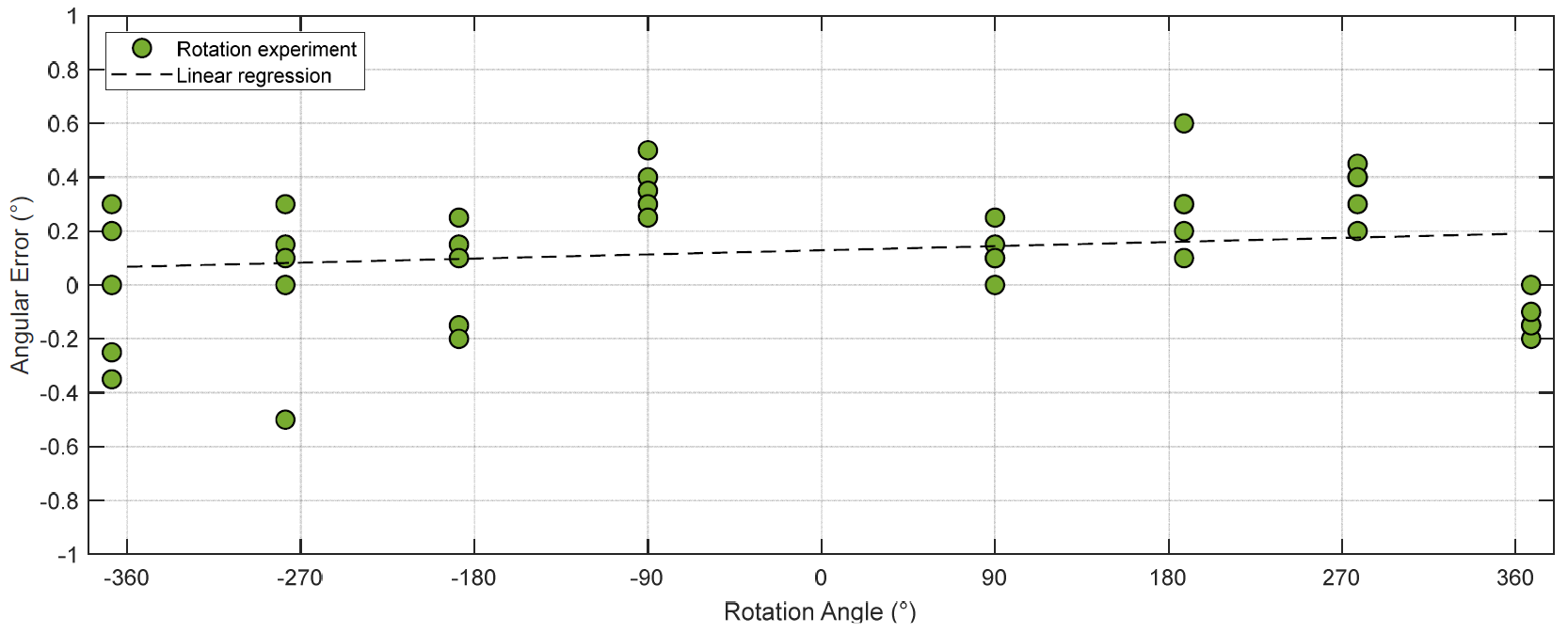
Figure 10 illustrates the evolution of the angular error (ε) relative to the target rotation angles, 90°, 180°, 270°, and 360°, performed in both clockwise (CW) and counterclockwise (CCW) directions:
ε = θ m e a s θ T A R G E T ,
where θ m e a s is the final orientation of the platform and θ T A R G E T the target rotation angle of the experiment.
The evolution displayed in Figure 10 was measured in a simplified additional experiment performing single rotations of 90°, 180°, 270°, and 360°. The objective was to avoid the complexity of the repetition of the UMBmark experiments and focus attention on the correction of the rotation. As a result of the UMBmark calibration, the rotation error was reduced to 0.0671° per 90° of rotation, demonstrating the effectiveness of the correction process. However, the main problem observed during the development of the UMBmark calibration is the complexity of the trajectory experiments and the need to realize three different UMBmark experiments to calibrate a three-wheeled omnidirectional mobile platform (Figure 7).

3.2. Direct Rotation Calibration

As an alternative to the complexity of the UMBmark experiments, this subsection proposes the development of direct rotation calibration experiments inspired by the work of Tomasi et al. [25]. To this end, a series of single-rotation experiments will be conducted to quantify systematic angular rotation errors in the TRIA-BOT platform.
Four target rotation angles were tested: 90°, 180°, 270°, and 360°. For each target rotation angle, five open-loop tests were performed in the clockwise (CW) direction and five in the counterclockwise (CCW) direction, resulting in a total of forty rotation experiments. After each test, the final orientation of the platform ( θ m e a s ) was compared with the target rotation angle of the experiment, ( θ T A R G E T ) , to calculate the angular error (ε) obtained in each rotation experiment (Equation (13)). Figure 11 shows some images of the final orientation of the mobile platform after conducting some CW rotation experiments.
Figure 12 shows the evolution of the angular error (ε) relative to the target rotation of the platform, 90°, 180°, 270°, and 360°, in both CW and CCW directions. The measurement resolution was 0.01° and all tests were performed at a constant angular velocity of 0.6 rad/s. As a reference, the linear regression of the results predicts an average angular rotation error of around 1.66° for every 90° rotation increase.
The linear regression that models the evolution of the angular rotation error relative to the target angular rotation of the platform can be used to directly estimate a corrected target rotation for the platform ( θ P L A T F O R M ) required to achieve the expected target angular rotation:
θ P L A T F O R M = θ T A R G E T 1 + 0.018483 0.246250
Therefore, any target angular rotation ( θ T A R G E T ) must be corrected using Equation (14) to obtain the real angular rotation ( θ P L A T F O R M ) that must be sent to the servomotors driving the wheels of the omnidirectional platform.
Finally, after this correction, Figure 13 illustrates the evolution of the angular error (ε) relative to the target rotation angles, 90°, 180°, 270°, and 360°, performed in both clockwise (CW) and counterclockwise (CCW) directions: As a result of this direct calibration, the rotation error was reduced to 0.0207° per 90° of rotation. These results improved by a factor of 3 (0.0671° per 90° of rotation) in the UMBmark calibration, demonstrating the effectiveness of a direct rotation calibration method.

4. Correction of Forward Displacement Errors

This section addresses the calibration of the systematic forward displacement errors of the TRIA-BOT omnidirectional platform. Two calibration procedures are compared: the result obtained with the UMBmark calibration, and the result obtained with a direct forward displacement calibration.

4.1. UMBmark Forward Displacement Calibration

This subsection is focused on the calibration of the rotation of the TRIA-BOT platform from the results of the UMBmark [21] calibration method. Based on the trajectory results presented in Figure 9 and Table 1 and using Equations (5)–(7), the orientation error angle ( β U M B ) was then calculated for each orientation. Table 3 presents the corresponding values of the orientation error angle obtained for the three assessed orientations (see Figure 7).
Then, by using Equations (8)–(11), we can calculate the radius of curvature ( R ), the ratio between the two wheels’ diameters ( E d ) and the corrected diameters ( D L   a n d   D R ) for the left and right wheels in each orientation. Table 4 summarizes the results of the application of the previous equations, obtaining the corrected wheel diameters, D L   and   D R .
The corrected wheel diameters D L and D R are used to compensate for unequal wheel diameters in differential-drive robots. However, in the case of a three-wheeled omnidirectional platform, this correction method has no application because each wheel is affected by two uncorrelated dimensional parameters ( D L and D R ) so the application of the correction factors to wheels is not feasible. As a result, the UMBmark procedure cannot be used to correct straight-line motion errors in the TRIA-BOT omnidirectional platform.

4.2. Direct Forward Displacement Calibration

As an alternative to the UMBmark procedure, this section proposes the development of direct forward displacement calibration experiments inspired by the work of Ivanjko et al. [27]. To this end, a series of single-displacement experiments will be conducted to quantify systematic displacement errors in the TRIA-BOT platform.
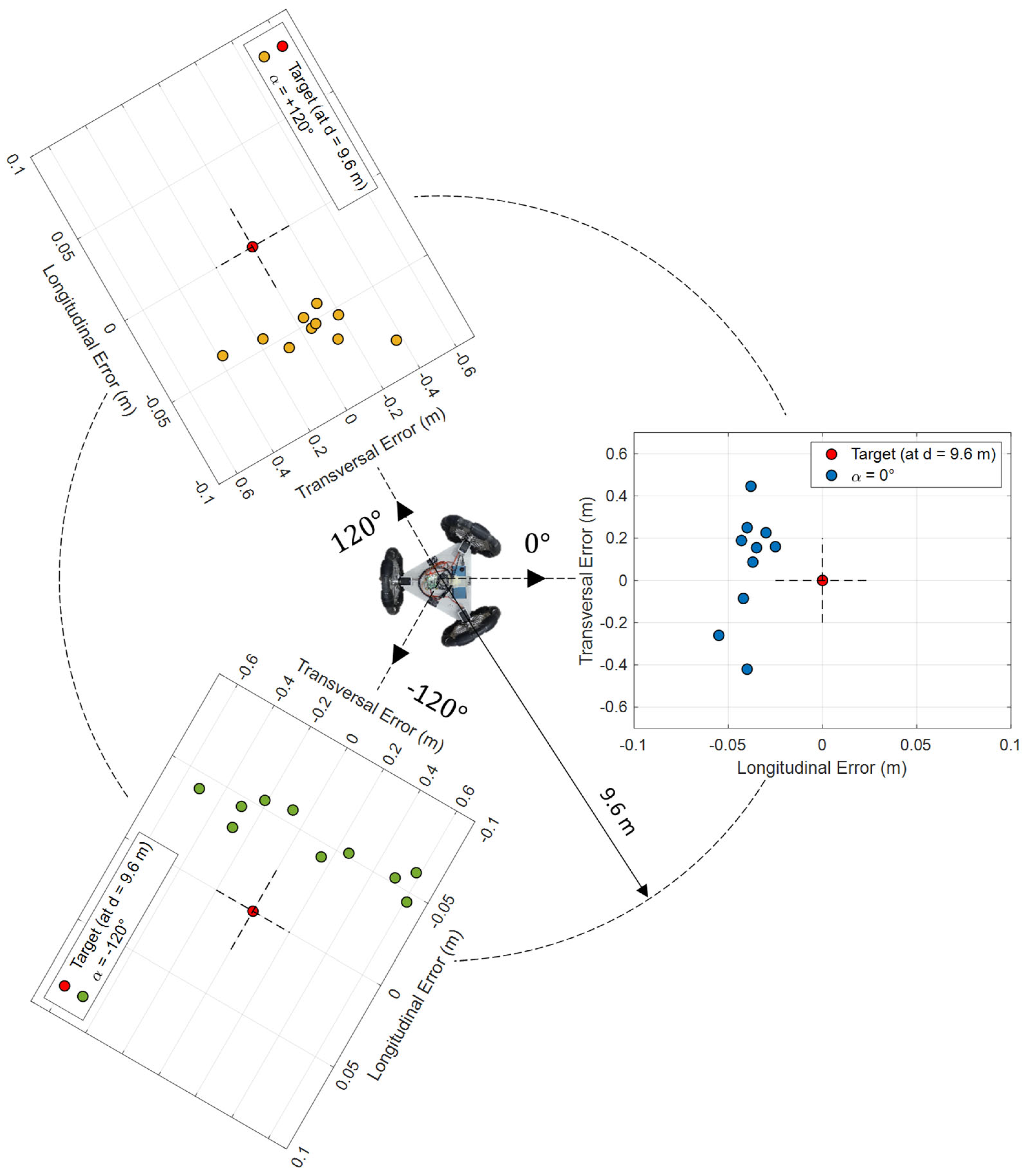
Three representative angular orientations were tested: 0°, 120°, and -120°. For each orientation, 10 tests were performed, resulting in a total of 30 displacement experiments. After each test, the final measured position of the platform ( x , y ) M E A S was compared with the intended target position, ( x , y ) T A R G E T , to calculate the displacement error (ε) for each trajectory. Figure 14 shows a schematic representation of the experiments conducted, along with the final positions reached by the platform in each case. In these experiments, the forward distance was limited to 9.6 m due to constraints imposed by the ground reference markers used during the displacement tests. In general, the results in Figure 14 show good accuracy and repeatability. The platform consistently falls slightly short of its target destination and exhibits smooth random deviations from its intended straight-line path.
The small and apparently random transversal error observed in Figure 14 is interpreted as a positioning error at the initial position of the platform, which becomes amplified during the 9.6 m forward displacement. The use of precision-machined solid aluminum components in the wheels, along with narrow 1 mm hard rubber coatings on the free rollers, helps to minimize systematic errors caused by unequal wheel diameters.
The correction of these systematic forward displacement errors was approached by averaging the longitudinal errors shown in Figure 14: −0.0385 m for the trajectory orientation of 0°, −0.0537m for 120°, and −0.0485 m for −120°. By assuming the systematic displacement error as the average of these longitudinal errors, the distance calibration implemented to the platform is
d i s t a n c e P L A T F O R M = ( 1 + 0.00488542 ) · d i s t a n c e T A R G E T ,
Therefore, any target displacement distance ( d i s t a n c e T A R G E T ) must be slightly increased to produce the actual displacement ( d i s t a n c e P L A T F O R M ) that must be sent to the servomotors driving the wheels of the omnidirectional platform. Figure 15 shows the improvement in longitudinal results achieved after applying the alternative calibration procedure to the TRIA-BOT platform. As described before, these improvements could not be obtained using the UMBmark calibration method, since it is specifically designed to correct discrepancies between two wheel diameters. Therefore, applying it independently to each of the three wheel pairs failed to yield physically meaningful results.

5. Discussion and Conclusions

This paper evaluates and corrects systematic odometry errors in a compact omnidirectional mobile platform equipped with three omni-wheels, each driven by a digital servomotor with velocity control capabilities. One advantage of a three-wheeled omnidirectional platform configuration is that its wheels are always in contact with the ground, so they are not prone to skidding. This is not the case of a four-wheeled omnidirectional platform in which the contact of the wheels with the ground is not guaranteed. The proposed platform is an indoor platform and has been experimentally assessed on a conventional flat ground.
The motion capabilities of the platform were experimentally assessed, and its systematic motion errors were analyzed and corrected using the UMBmark calibration method as a baseline reference, along with two direct calibration methods applied to rotational and linear displacements. The UMBmark calibration method [21] was originally developed for differential-drive platforms. The application of the calibration method to a three-wheeled omnidirectional platform assumes that the omnidirectional motion of the platform can be interpreted as the superposition of the motions of three differential-drive platforms, each oriented at 0°, 120°, and −120°. Based on this assumption, the two reference square paths defined in the UMBmark procedure, each executed in both CW and CCW directions, were extended to six paths, one for each orientation (see Figure 7).
The results of applying the UMBmark procedure for calibrating the rotational motion of the platform demonstrated a significant improvement. The rotation error was reduced from 1.66° to 0.0671° per 90° turn. However, a simple direct calibration method further improved the error to 0.0207° per 90° turn, while also avoiding the complexity associated with executing the six square paths required by the UMBmark procedure (see Figure 7).
In contrast, the results of applying the UMBmark procedure for calibrating the straight-line displacement of the platform have shown inapplicable results. This limitation arises from the fact that each trajectory orientation (0°, 120°, and −120°) involves two wheels, meaning that each wheel must satisfy multiple, and sometimes conflicting, correction constraints. For example, wheel 1 cannot have a larger diameter than wheel 2 if wheel 2 is also required to be larger than wheel 3, and wheel 3, in turn, must be larger than wheel 2. The inapplicability of the calibration results was due to the use of three uncorrelated UMBmark calibrations, each applied independently to a different pair of wheels. Despite these results, a direct forward displacement calibration applied individually to the three orientations (0°, 120°, and −120°) was able to reduce systematic longitudinal errors in the mobile platform.
The final motion capabilities achieved with the TRIA-BOT confirm that a compact three-wheeled omnidirectional platform driven by servomotors can be used as a testbench for control algorithms and for trajectory-tracking experiments. Future works will explore the implementation of complex trajectories, the evaluation of the motion performances in outdoor conditions, and the coordinated execution of collaborative tasks involving multiple omnidirectional platforms.

Supplementary Materials

The following supporting information can be downloaded at: https://www.mdpi.com/article/10.3390/app151910700/s1. Video S1: ForwardMovementCalibrated; Video S2: ForwardMovementUncalibrated; Video S3: PureRotation360Calibrated; Video S4: PureRotation360Uncalibrated.

Author Contributions

Conceptualization, D.M., E.R. and J.P.; software, D.M. and R.B.; validation, D.M., E.R., R.B. and J.P.; formal analysis, D.M. and J.P.; investigation, D.M., E.R. and J.P.; resources, R.B.; writing—original draft preparation, J.P.; writing—review and editing, J.P. All authors have read and agreed to the published version of the manuscript.

Funding

This research was partially funded by Ministerio de Ciencia, Innovación y Universidades: FPU22/00526; and Departament de Recerca i Universitats: AGAUR FI SDUR 2022.

Data Availability Statement

Data is contained within the article and Supplementary Material.

Conflicts of Interest

The authors declare no conflicts of interest. The funders had no role in the design of the study; in the collection, analyses, or interpretation of data; in the writing of the manuscript; or in the decision to publish the results.

References

  1. Sesmero, C.P.; Buonocore, L.R.; Di Castro, M. Omnidirectional Robotic Platform for Surveillance of Particle Accelerator Environments with Limited Space Areas. Appl. Sci. 2021, 11, 6631. [Google Scholar] [CrossRef]
  2. Tavakoli, M.; Viegas, C.; Marques, L.; Pires, J.N.; de Almeida, A.T. OmniClimbers: Omni-Directional Magnetic Wheeled Climbing Robots for Inspection of Ferromagnetic Structures. Robot. Auton. Syst. 2013, 61, 997–1007. [Google Scholar] [CrossRef]
  3. Song, H.; Wu, Y.; Wu, Y.; Zhou, G.; Luo, C. Two-Vehicle Coordination System for Omnidirectional Transportation Based on Image Processing and Deviation Prediction. J. Control Autom. Electr. Syst. 2021, 32, 875–883. [Google Scholar] [CrossRef]
  4. Orozco-Magdaleno, E.C.; Gómez-Bravo, F.; Castillo-Castañeda, E.; Carbone, G. Evaluation of Locomotion Performances for a Mecanum-Wheeled Hybrid Hexapod Robot. IEEE/ASME Trans. Mechatron. 2021, 26, 1657–1667. [Google Scholar] [CrossRef]
  5. Palacín, J.; Clotet, E.; Martínez, D.; Martínez, D.; Moreno, J. Extending the Application of an Assistant Personal Robot as a Walk-Helper Tool. Robotics 2019, 8, 27. [Google Scholar] [CrossRef]
  6. Gao, Z.Q.; Chen, H.B.; Du, Y.P.; Wei, L. Design and Development of an Omni-Directional Mobile Robot for Logistics. Appl. Mech. Mater. 2014, 602–605, 1006–1010. [Google Scholar] [CrossRef]
  7. Levratti, A.; Riggio, G.; Fantuzzi, C.; De Vuono, A.; Secchi, C. TIREBOT: A Collaborative Robot for the Tire Workshop. Robot. Comput.-Integr. Manuf. 2019, 57, 129–137. [Google Scholar] [CrossRef]
  8. Raczl, S.-G.; Crenganis, M.; Barsan, A.; Adrian, M. Omnidirectional Autonomous Mobile Robot With Mecanum Wheel. In Proceedings of the International Student Innovation and Scientific Research Exhibition, Sibiu, Romania, 1 April 2019. [Google Scholar]
  9. Li, Y.; Dai, S.; Zhao, L.; Yan, X.; Shi, Y. Topological Design Methods for Mecanum Wheel Configurations of an Omnidirectional Mobile Robot. Symmetry 2019, 11, 1268. [Google Scholar] [CrossRef]
  10. Almasri, E.; Uyguroğlu, M.K. Modeling and Trajectory Planning Optimization for the Symmetrical Multiwheeled Omnidirectional Mobile Robot. Symmetry 2021, 13, 1033. [Google Scholar] [CrossRef]
  11. Mohanraj, A.P.; Elango, A.; Reddy, M.C. Front and Back Movement Analysis of a Triangle-Structured Three-Wheeled Omnidirectional Mobile Robot by Varying the Angles between Two Selected Wheels. Sci. World J. 2016, 2016, 7612945. [Google Scholar] [CrossRef]
  12. Yan, G.-R.; Zhang, H.-B. A New Kind of Wheel-Model All Directional Moving Mechanism. J. Harbin Inst. Technol. 2001, 33, 854–857. [Google Scholar]
  13. Salih, J.E.M.; Rizon, M.; Yaacob, S.; Adom, A.H.; Mamat, M.R. Designing Omni-Directional Mobile Robot with Mecanum Wheel. Am. J. Appl. Sci. 2006, 3, 1831–1835. [Google Scholar] [CrossRef]
  14. Rey, R.; Cobano, J.A.; Corzetto, M.; Merino, L.; Alvito, P.; Caballero, F. A Novel Robot Co-Worker System for Paint Factories without the Need of Existing Robotic Infrastructure. Robot. Comput. Integr. Manuf. 2021, 70, 102122. [Google Scholar] [CrossRef]
  15. Huang, Y.; Meng, R.; Yu, J.; Zhao, Z.; Zhang, X. Practical Obstacle-Overcoming Robot with a Heterogeneous Sensing System: Design and Experiments. Machines 2022, 10, 289. [Google Scholar] [CrossRef]
  16. Tian, P.; Zhang, Y.N.; Zhang, J.; Yan, N.M.; Zeng, W. Research on Simulation of Motion Compensation for 8×8 Omnidirectional Platform Based on Back Propagation Network. Appl. Mech. Mater. 2013, 299, 44–47. [Google Scholar] [CrossRef]
  17. Borenstein, J.; Everett, H.R.; Feng, L. Where Am I? Sensors and Methods for Mobile Robot Positioning; University of Michigan: Ann Arbor, MI, USA, 1996. [Google Scholar]
  18. Borenstein, J.; Everett, H.R.; Feng, L.; Wehe, D. Mobile Robot Positioning: Sensors and Techniques. J. Robot. Syst. 1997, 14, 231–249. [Google Scholar] [CrossRef]
  19. Abbas, T.; Arif, M.; Ahmed, W. Measurement and Correction of Systematic Odometry Errors Caused by Kinematics Imperfections in Mobile Robots. In Proceedings of the 2006 SICE-ICASE International Joint Conference, Busan, Republic of Korea, 18 October 2006. [Google Scholar]
  20. Gargiulo, A.M.; di Stefano, I.; Genova, A. Model-Based Slippage Estimation to Enhance Planetary Rover Localization with Wheel Odometry. Appl. Sci. 2021, 11, 5490. [Google Scholar] [CrossRef]
  21. Borenstein, J.; Feng, L. Measurement and Correction of Systematic Odometry Errors in Mobile Robots. IEEE Trans. Robot. Autom. 1996, 12, 869–880. [Google Scholar] [CrossRef]
  22. Lee, K.; Jung, C.; Chung, W. Accurate Calibration of Kinematic Parameters for Two Wheel Differential Mobile Robots. J. Mech. Sci. Technol. 2011, 25, 1603–1611. [Google Scholar] [CrossRef]
  23. Wang, D.; Xu, M.; Chen, Y.; Zhong, H.; Zhu, Y.; Wang, Z.; Gao, L. Positioning Method of Four-Wheel-Steering Mobile Robots Based on Improved UMBmark of Michigan Benchmark Algorithm. J. Adv. Comput. Intell. Intell. Inform. 2023, 27, 135–142. [Google Scholar] [CrossRef]
  24. Sousa, R.B.; Petry, M.R.; Moreira, A.P. Evolution of Odometry Calibration Methods for Ground Mobile Robots. In Proceedings of the 2020 IEEE International Conference on Autonomous Robot Systems and Competitions (ICARSC), Ponta Delgada, Portugal, 15 April 2020. [Google Scholar]
  25. Tomasi, D.L.; Todt, E. Rotational Odometry Calibration for Differential Robot Platforms. In Proceedings of the 2017 Latin American Robotics Symposium (LARS) and 2017 Brazilian Symposium on Robotics (SBR), Curitiba, Brazil, 8–11 November 2017. [Google Scholar]
  26. Bostani, A.; Vakili, A.; Denidni, T.A. A Novel Method to Measure and Correct the Odometry Errors in Mobile Robots. In Proceedings of the 2008 Canadian Conference on Electrical and Computer Engineering, Niagara Falls, ON, Canada, 4–7 May 2008. [Google Scholar]
  27. Ivanjko, E.; Komšić, I.; Petrović, I. Simple Off-Line Odometry Calibration of Differential Drive Mobile Robots. In Proceedings of the 16th International Workshop on Robotics in Alpe-Adria-Danube Region, Ljubljana, Slovenia, 7 June 2007. [Google Scholar]
  28. Jung, C.; Chung, W. Calibration of Kinematic Parameters for Two Wheel Differential Mobile Robots by Using Experimental Heading Errors. Int. J. Adv. Robot. Syst. 2011, 8, 68. [Google Scholar] [CrossRef]
  29. Antonelli, G.; Chiaverini, S.; Fusco, G. A Calibration Method for Odometry of Mobile Robots Based on the Least-Squares Technique: Theory and Experimental Validation. IEEE Trans. Robot. 2005, 21, 994–1004. [Google Scholar] [CrossRef]
  30. Mondal, S.; Yun, Y.; Chung, W.K. Terminal Iterative Learning Control for Calibrating Systematic Odometry Errors in Mobile Robots. In Proceedings of the 2010 IEEE/ASME International Conference on Advanced Intelligent Mechatronics, Montreal, QC, Canada, 6–9 July 2010. [Google Scholar]
  31. De Giorgi, C.; De Palma, D.; Parlangeli, G. Online Odometry Calibration for Differential Drive Mobile Robots in Low Traction Conditions with Slippage. Robotics 2024, 13, 7. [Google Scholar] [CrossRef]
  32. Censi, A.; Franchi, A.; Marchionni, L.; Oriolo, G. Simultaneous Calibration of Odometry and Sensor Parameters for Mobile Robots. IEEE Trans. Robot. 2013, 29, 475–492. [Google Scholar] [CrossRef]
  33. Cantelli, L.; Ligama, S.; Muscato, G.; Spina, D. Auto-Calibration Methods of Kinematic Parameters and Magnetometer Offset for the Localization of a Tracked Mobile Robot. Robotics 2016, 5, 23. [Google Scholar] [CrossRef]
  34. Maddahi, Y.; Maddahi, A.; Sepehri, N. Calibration of Omnidirectional Wheeled Mobile Robots: Method and Experiments. Robotica 2013, 31, 969–980. [Google Scholar] [CrossRef]
  35. Lin, P.; Liu, D.; Yang, D.; Zou, Q.; Du, Y.; Cong, M. Calibration for Odometry of Omnidirectional Mobile Robots Based on Kinematic Correction. In Proceedings of the 2019 14th International Conference on Computer Science & Education (ICCSE), Toronto, ON, Canada, 19 August 2019. [Google Scholar]
  36. Savaee, E.; Hanzaki, R.A. A New Algorithm for Calibration of an Omni-Directional Wheeled Mobile Robot Based on Effective Kinematic Parameters Estimation. J. Intell. Robot. Syst. 2021, 101, 28. [Google Scholar] [CrossRef]
  37. Palacín, J.; Rubies, E.; Clotet, E. Systematic Odometry Error Evaluation and Correction in a Human-Sized Three-Wheeled Omnidirectional Mobile Robot Using Flower-Shaped Calibration Trajectories. Appl. Sci. 2022, 12, 2606. [Google Scholar] [CrossRef]
  38. Sousa, R.B.; Petry, M.R.; Costa, P.G.; Moreira, A.P. OptiOdom: A Generic Approach for Odometry Calibration of Wheeled Mobile Robots. J. Intell. Robot. Syst. 2022, 105, 39. [Google Scholar] [CrossRef]
  39. Palacín, J.; Rubies, E.; Bitriá, R.; Clotet, E. Non-Parametric Calibration of the Inverse Kinematic Matrix of a Three-Wheeled Omnidirectional Mobile Robot Based on Genetic Algorithms. Appl. Sci. 2023, 13, 1053. [Google Scholar] [CrossRef]
  40. Moreno, J.; Clotet, E.; Lupiañez, R.; Tresanchez, M.; Martínez, D.; Pallejà, T.; Casanovas, J.; Palacín, J. Design, Implementation and Validation of the Three-Wheel Holonomic Motion System of the Assistant Personal Robot (APR). Sensors 2016, 16, 1658. [Google Scholar] [CrossRef]
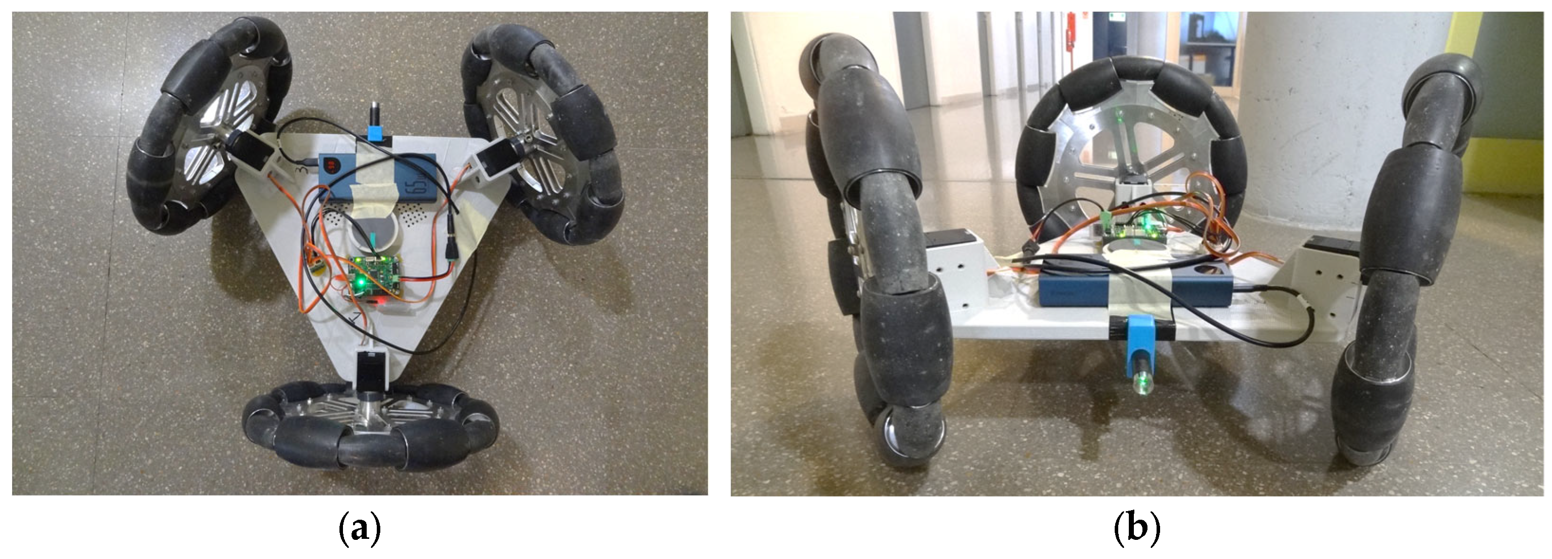
Figure 1. Zenithal (a) and frontal (b) images of the TRIA-BOT mobile platform.
Applsci 15 10700 g001
Figure 2. Schematic representation of the electric and electronic parts used in the TRIA-BOT platform: servomotors, power bank and platform controller.
Applsci 15 10700 g002
Figure 3. Image of the omnidirectional wheel used on the TRIA-BOT platform: (a) full view; (b) close-up of the passive rollers and the inter-roller gap.
Applsci 15 10700 g003
Figure 4. Snapshot of the 3D printing process of the TRIA-BOT platform base using a Creality S5 printer equipped with a 0.8 mm nozzle. The image shows the tri-hexagon infill pattern at 25% density, along with support holes. Other details: 0.4 mm layer height, 26 h total print time, and 697 g of white PLA used.
Applsci 15 10700 g004
Figure 5. Illustration of the Type A (a) and Type B (b) errors during a counterclockwise (CCW) execution of the bidirectional square path experiment.
Applsci 15 10700 g005
Figure 6. Representation of the calibration parameters evaluated in the TRIA-BOT platform.
Applsci 15 10700 g006
Figure 7. Illustration of the six different trajectories required by the UMBmark calibration method implemented in a three-wheeled omnidirectional platform.
Applsci 15 10700 g007
Figure 8. Combination of images obtained during a CW UMBmark experiment. The image shows the omnidirectional platform at different time samples while executing the square path experiment.
Applsci 15 10700 g008
Figure 9. Results of the final x position and y position obtained from the UMBmark experiment while performing the square path trajectory in an open loop and in the CW and CCW directions.
Applsci 15 10700 g009
Figure 10. Evolution of the rotation angular error after the UMBmark calibration. Evolution registered in 40 single open-loop rotation experiments, corresponding to target angles of 90°, 180°, 270°, and 360° in CW and CCW directions. The dotted line depicts the linear regression of the errors registered.
Applsci 15 10700 g010
Figure 11. Initial (a) and final orientation of the mobile platform after performing a CW rotation of −90° (b), −180° (c), −270° (d), and −360° (e).
Applsci 15 10700 g011
Figure 12. Evolution of the rotation angular error of the mobile platform registered in 40 pure-rotation experiments, corresponding to target angles of 90°, 180°, 270°, and 360° in CW and CCW directions. The dotted line depicts the linear regression of the error evolution.
Applsci 15 10700 g012
Figure 13. Evolution of the rotation angular error after a direct open-loop calibration. Evolution registered in 40 single-rotation experiments, corresponding to target angles of 90°, 180°, 270°, and 360° in CW and CCW directions. The dotted line depicts the linear regression of the errors.
Applsci 15 10700 g013
Figure 14. Relative distance error measured during open-loop forward calibration experiments at angular orientations 0°, 120°, and −120°.
Applsci 15 10700 g014
Figure 15. Relative error after distance calibration in the open-loop forward displacement experiments performed at the angular orientations 0°, 120°, and −120°.
Applsci 15 10700 g015
Table 1. Results of the center of gravity of the final positions for the CW and CCW runs in all three orientations.
Orientations x c . g . , C W x c . g . , C C W y c . g . , C W y c . g . , C C W
0 ° 0.14580.09360.1714−0.1266
120 ° 0.10600.18000.1002−0.201
120 ° 0.17420.12580.2014−0.1404
Table 2. Results of the rotation error angle obtained by applying Equations (1)–(3).
Orientations α x α y
0 ° −1.3716−1.7074
120 ° −1.6386−1.7257
120 ° −1.7188−1.9583
Table 3. Results of the orientation error angle obtained by applying Equations (5)–(7).
Orientations β x β y β U M B
0 ° −0.2991−0.2566−0.2778
120 ° −0.4239−0.5775−0.5007
120 ° −0.2773−0.3495−0.3134
Table 4. Results of the radius of curvature, ratio between the two wheels’ diameters and corrected wheel diameters obtained by applying Equations (8)–(11).
Orientations R E d D L D R
0 ° −515.460.999210.299130.29890
120 ° 286.041.001420.298800.29923
120 ° −457.040.999110.299150.29888
Disclaimer/Publisher’s Note: The statements, opinions and data contained in all publications are solely those of the individual author(s) and contributor(s) and not of MDPI and/or the editor(s). MDPI and/or the editor(s) disclaim responsibility for any injury to people or property resulting from any ideas, methods, instructions or products referred to in the content.