Article

Metamaterial-Enhanced Microstrip Antenna with Integrated Channel Performance Evaluation for Modern Communication Networks

by
Jasim Khudhair Salih Turfa
1,* and
Oguz Bayat
2
1
Electrical and Computer Engineering College, Altinbas University, 34217 Istanbul, Turkey
2
Department of Electrical and Electronics Engineering, Yeditepe University, 34755 Istanbul, Turkey
*
Author to whom correspondence should be addressed.
Appl. Sci. 2025, 15(19), 10692; https://doi.org/10.3390/app151910692
Submission received: 28 August 2025 / Revised: 16 September 2025 / Accepted: 22 September 2025 / Published: 3 October 2025

Abstract

This paper investigates the channel performance through a high-gain, circularly polarized microstrip patch antenna that is developed for contemporary wireless communication systems. The proposed antenna creates two orthogonal modes for circular propagation with slightly varying resonance frequencies by using a cross line and truncations to circulate surface currents. Compactness, reduced surface wave losses, and enhanced impedance bandwidth are made possible by the coaxial probe feed, periodic electromagnetic gap (EBG) slots, and fractal patch geometry. For in-phase reflection and beam focusing, a specially designed single-layer metasurface (MTS) reflector with an 11 × 11 circular aperture array is placed 20 mm behind the antenna. A log-normal shadowing model was used to test the antenna in real-world scenarios, and the results showed a strong correlation between the model predictions and actual data. At up to 250 m, the polarization-agile, high-gain antenna demonstrated reliable performance across a variety of channel conditions, enabling accurate characterization of the Channel Quality Indicator (CQI), Signal-to-Noise Ratio (SNR), and Reference Signal Received Power (RSRP). By combining cutting-edge antenna architecture with an empirical channel performance study, this research presents a compact, affordable, and fabrication-friendly solution for increased wireless coverage and efficiency.

1. Introduction

Ultra-reliable low-latency links, immersive broadband, and massive machine-type connectivity across a variety of environments are the goals of fifth-generation (5G) and emerging sixth-generation (6G) wireless systems [1,2,3]. An accurate understanding of radio wave propagation is necessary to support realistic cell planning, interference control, and key performance indicator (KPI) budgeting in order to achieve these goals [4]. Field measurements continue to be the gold standard for validating assumptions and calibrating channel models under actual mobility and hardware constraints, even though advanced system-level simulators are useful [5,6].
Wide-area coverage is still supported by Sub-6 GHz deployments, which supplement the more recent terahertz (THz) and millimeter-wave (mmWave) bands that provide high data rates and energy efficiency [7]. Long-distance path-loss models with log-normal shadowing are frequently used to describe large-scale outdoor propagation in order to account for macroscopic obstacles [8,9]. Parameterized models for urban, suburban, and rural scenarios from 0.5 to 100 GHz are provided by standardized references, including 3GPP TR 38.901 and ITU-R P.1411, P.1238, and COST-231 [10]. However, in order to account for area morphology, vegetation, building materials, traffic dynamics, and unusual antenna placements, these models need to be locally calibrated [11].
The statistical aggregates required to assess the path-loss exponent (γ), log-normal standard deviation, and mobility KPIs like RSRP, SNR/SINR, and CQI are provided by carefully thought-out drive-test campaigns [12]. At the same time, achievable rates are significantly impacted by the radio front-end (RFE): link adaptation and energy efficiency are shaped by receiver noise figure, linearity, and quantization constraints as carrier frequency, bandwidth, and array size increase [13,14]. According to some researchers, 6G information-theoretic models must thus strike a balance between spectral efficiency and power consumption [15].
Propagation and network design are further impacted by rapid advancements in antenna systems. Cost-effective phased arrays, wide-angle beam scanners, and reconfigurable intelligent surfaces (RISs/IRSs), which are frequently managed by machine learning, aid in reducing interference, counteracting path loss, and enabling joint communication-sensing (JCAS) capabilities [16,17]. Particularly appealing for shared radar-communication MIMO systems functioning under stringent hardware constraints are hybrid analog–digital beamforming and flexible RF-chain selection [18].
Using a meticulously planned drive-test methodology, this work provides an experimentally validated assessment of outdoor cellular propagation in heterogeneous settings [19]. A log-normal shadowing framework is used to model measurements of RSRP, SNR, and CQI across representative urban and rural routes, and mean-square-error minimization is used to estimate the path-loss exponent γ [20,21]. The faster attenuation seen in dense areas is highlighted by two region-specific models, one for the urban area and one for the rural area [22]. (i) Guidance for coverage planning and interference budgeting [23,24]; (ii) calibration anchors for system-level simulators studying beamforming, MIMO, and mobility [25]; and (iii) insights that connect achievable spectral efficiency to RFE constraints and beamforming strategies for energy-aware 6G design [26,27] are all provided by the resulting KPI trends and empirically calibrated parameters.
A high-gain circularly polarized microstrip patch antenna with improved polarization purity and a gain of 14.8 dBi is presented in this paper. It is designed for 5G applications. Additionally, it uses a beam-steering mechanism that can be reconfigured to control the radiation pattern dynamically. Drive tests for urban and rural locations confirm the proposed antenna’s real-world performance. The use of metamaterial (MTM) structures is adopted to provide a low-cost solution with high scalability for next-generation wireless networks. These achievements provide a full framework for optimizing 5G/6G networks in different environments to bridge the gap between advanced antenna design and empirical propagation studies.

2. Antenna Design Specifications

2.1. Antenna Geometry

The proposed antenna design, appropriate for subsequent drive tests in authentic wireless communication settings, is a circularly polarized microstrip patch antenna affixed to an FR-4 epoxy substrate with a relative permittivity of 4.3, a loss tangent of 0.02, and a thickness of 1.6 mm, intended for operation at 0.915 GHz. A 50 Ω SMA port is used to feed the antenna patch at the corner of the cross-slot edges to generate circular polarization. The disruption of the surface current distribution generates a spinning electric field vector that emits circularly polarized waves, causing the degenerate TM01 and TM10 modes to separate into two orthogonal modes with marginally distinct resonance frequencies. The substrate occupies an area of 173 × 173 mm2, and the patch width is 74 mm, mounted on top of a 60 × 74 mm2 ground aperture as shown in Figure 1. The feed probe connects to the back patch surface at 10.70 mm from the width edge and 14.50 mm from the bottom edge. The periodic array of circular slots in the ground plane functions as an EBG structure to inhibit surface wave propagation. The suggested patch structure recommends MTM-inspired filters, which effectively diminish surface waves while enhancing operating bandwidth via tailored effective constitutive parameters. Due to the fact of structure symmetry and MTM locations from the proposed patch, the generated orthogonal modes retain phase coherence [6], which realizes high polarization purity [10]. The proposed design works would be well-suited for modern wireless networks. Using an FR-4 substrate ensures low fabrication costs in comparison to other commercial substrates. This antenna coaxial feed placement, MTM-inspired slotting, and EBG ground plane patterning combine to provide a practical solution for contemporary wireless systems that need radiators that are polarization-agile, compact, and efficient.

2.2. Reflector Geometrical Details

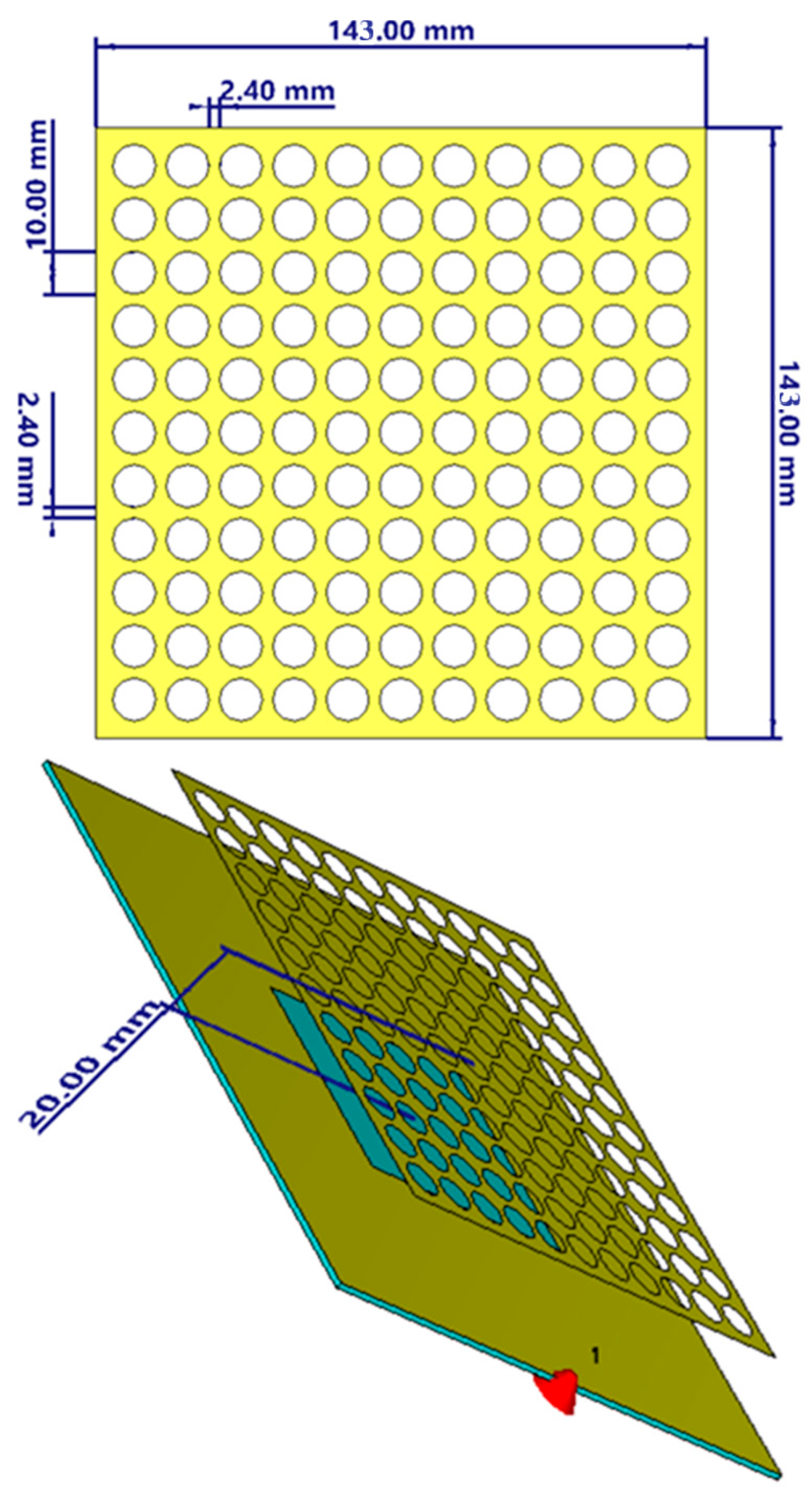
The proposed MTS reflector consists of a single layer including an array of 11 × 11-unit cells organized inside a circular aperture with a diameter of 10 mm. Two consecutive unit cells are etched as perforations on a copper screen, separated by a distance of 2.4 mm. The copper screen spans 143 × 143 mm2 to accommodate the reflector, positioned 20 mm from the antenna. This distance was selected to ensure in-phase reflection at an integer multiple of half a wavelength. Moreover, by attaining subwavelength dimensions for each unit cell, the proposed unit cell measurements are considered to provide a consistent MTM layer configuration. Capacitive coupling may occur between the copper screen underneath the antenna structure and the proposed reflector composed of the MTM layer. Figure 2 illustrates the residual geometrical specifications of the proposed reflector.
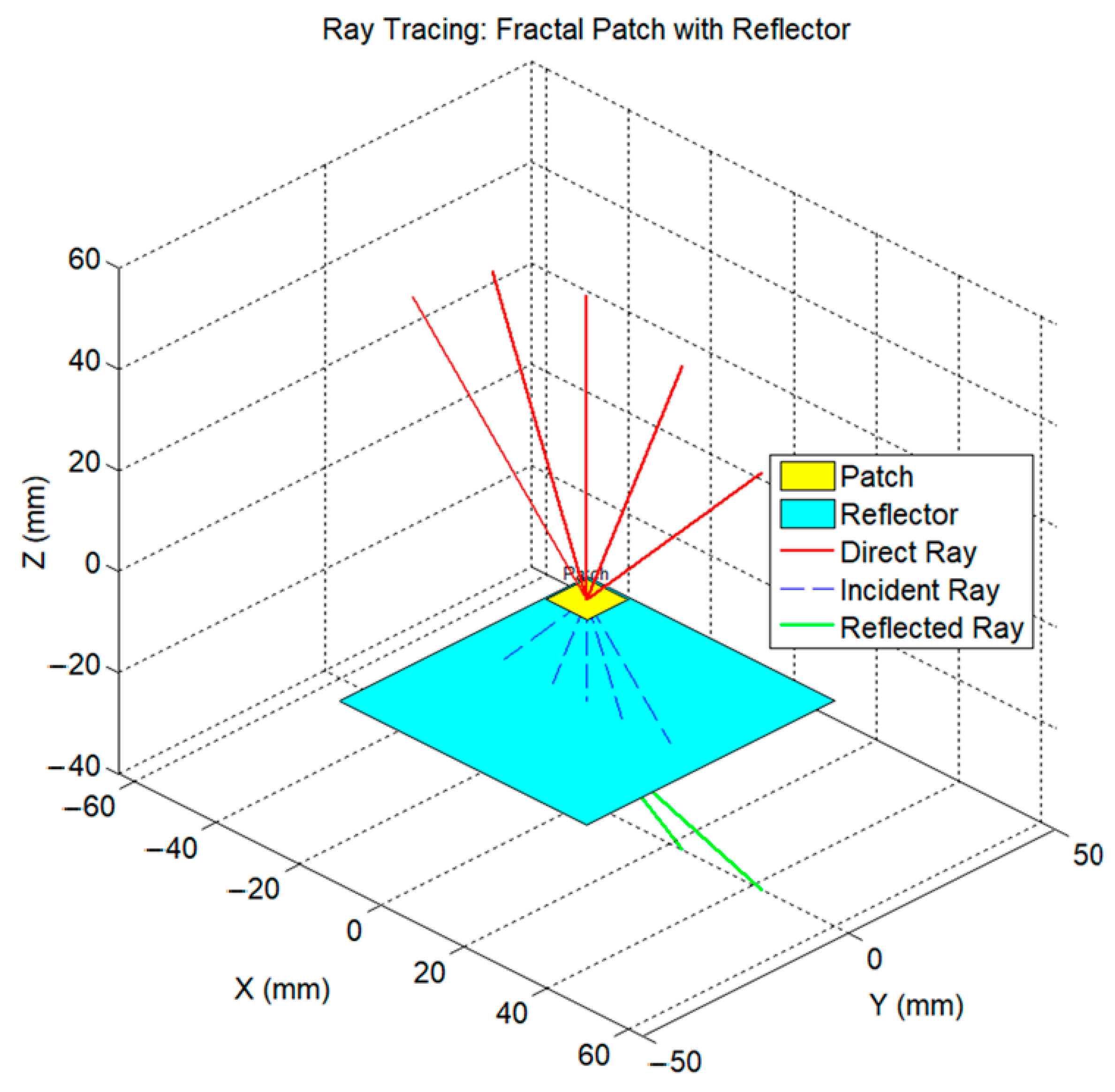
The proposed antenna structure was based on the design presented in [12], which used a fractal H-shaped geometry fed by a microstrip line. As seen in Figure 1, the current work enhances performance by combining this fractal patch with a specially designed reflector layer that is positioned on the antenna backside. The reflector is strategically placed 20 mm from the ground plane bottom, or the focal point of the radiated beam, in Figure 3. Such a structure extensively increases the electromagnetic radiation gain through suppressing side- and back-lobes by reflecting them toward the boresight [3]. The reflector improves the forward-directed beam from a physics point of view by constructively rerouting dispersed fields such that they are in phase with the direct radiation [7]. The design aims to concentrate the radiated energy along the boresight (Go) direction to maximize directivity and gain and generate paraxial beam rays. This concentrating effect is very important for antennas that need high gain and a narrow beamwidth, such as those used in radar systems and satellite communication. The focusing behavior is controlled by reducing the beamwidth in both the ϴ- and φ-cut planes. The beamwidth reduction relation presented in [3] provides an analytical explanation for this. Overall, the reflector structure and the fractal H-shaped patch combine to create a small, high-gain antenna design with improved radiation pattern characteristics. This makes it perfect for modern wireless systems that require efficient directional radiators with a compact spatial footprint.
G o 30,000 φ θ  

3. Reflector Characterizations

The proposed 11 × 11 circular aperture reflector structure, which works at 0.915 GHz with a near-zero reflection phase [21], may be explained by classical electromagnetics based on Maxwell equations and standard MTM theory. As presented in Figure 4, the proposed structure operates as an MTS reflector to provide in-phase reflection over the frequency band of interest around 0.915 GHz. To examine the impact of the aperture diameter on the reflector performance, we altered it from 8 mm to 12 mm in steps of 2 mm. The reflection spectra recorded a low phase around the resonant frequency, which suggests effective reflection and little backscattering, which is consistent with zero-reflection phase values for positive interference [22]. This design strengthens the outgoing wavefront and enhances the far-field radiation pattern by allowing the incoming wave to be reflected with the same phase at every location on the surface [23]. A customized surface impedance is created by the subwavelength scattering of a reflective ground plane array of circular apertures [24]. The configuration of the apertures guarantees the continuity of the tangential components of the electric and magnetic fields across the MTS interface, in accordance with Maxwell boundary requirements. These conditions result in the requisite local surface reactance [25]. The designer can attain a phase response approaching zero throughout the aperture array at the specified frequency by adjusting the effective permittivity and permeability through the modulation of aperture dimensions and their periodicity [26]. Zero-phase reflection induces constructive interference, making each wave that strikes the surface more direct. Such a method may be useful for the proposed antenna design that is intended to avoid additional size while incorporating a high-gain reflector. A quasi-isotropic response, using circular holes organized in a symmetric array of 11 × 11 configuration, enables polarization-insensitive behavior and enhances angular constancy throughout the reflection phase [27]. Depending on the intricacy of the unit cell, the classical analysis also involves resolving the boundary value issue for the electric and magnetic fields by methods such as mode-matching or integral equations [28]. Circular apertures alter the local boundary conditions to enable leaky modes that emit with a variable phase, hence disturbing the current distribution on the ground plane. This technique, based on classical electromagnetics, allows engineering reflection by tailored wavefront control [29]. This facilitates beam modification, reduces radar cross-sections, and improves antenna efficiency. The reflection response validates the effectiveness of traditional design principles in metamaterials, using subwavelength structures to customize the macroscopic electromagnetic response.

4. Antenna Design Methodology

The evaluated S11 spectra and radiation patterns are utilized to see how well the antenna works. For this project, the antenna design is optimized in the following ways:

4.1. Antenna Performance

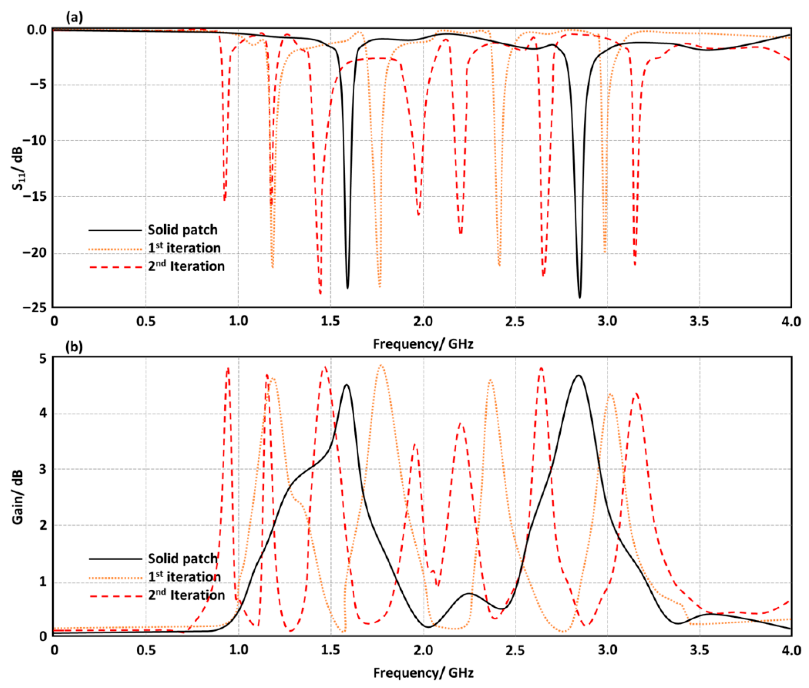
The suggested basic antenna is put through a numerical simulation test without the specified reflector. The shape of the antenna patch is based on a solid rectangle. The sold patch acquires fractal structure slots depending on the H-shape in the first and second iterations. We did not consider the 3rd order due to fabrication limitations in our facility, which cannot accommodate such complicated designs throughout the milling manufacturing process. We performed simulations under similar conditions to see fluctuations in S11 and gain spectra. The simulation process relies on the CTS MWS numerical algorithms derived from finite integral approach formulations. This kind of research is used to enhance the fundamental patch, ensuring it meets the requisite S11 and gain spectrum performance standards. The introduction to fractals says that the antenna mode number grows higher as the fractal iteration goes up. With a gain of 4.85 dBi, the suggested patch based on the second iteration is found to realize the minimum frequency resonance around 0.918 GHz, surpassing the other two geometries under consideration. As illustrated in Figure 5a, the second iteration achieves the first frequency resonance at 0.918 GHz with S11 below −10 dB and a gain of 4.85 dBi, as shown in Figure 5b.

4.2. Effect of Ground Plane Aperture

The full aperture beneath the antenna patch has been substituted for the full ground plane with a copper layer in the proposed antenna. In order to achieve effective size reduction, such an aperture is introduced to nature-matching enhancement and frequency reduction. This is carried out by altering the antenna ground plane aperture size to the solid ground plane from 60 × 74 mm2 to 30 × 37 mm2. The antenna exhibits a frequency resonance at 0.918 GHz with S11 below −10 dB, as shown in Figure 6a. As seen in Figure 6b, the antenna then exhibits gain enhancement to 4.85 dBi with an increase in the antenna ground plane aperture. To minimize skew wave fringing resulting from ground plane metal surface wave diffraction, the antenna ground plane aperture area must not exceed the dimensions of the main patch size [11].

4.3. MTM Filter Introduction

As seen in Figure 1, the suggested antenna patch is encircled by MTM filters made of seven-unit cells. As shown in Figure 7a, these filters are positioned to suppress surface waves, resulting in notable increases in antenna gain without compromising antenna bandwidth. As seen in Figure 7b, the introduction of the suggested MTM unit cells resulted in gain enhancements of 8.2 dBi. This study was conducted to perform a comparison between a design based on a classical metal planar ground without an aperture and another antenna design based on a ground plane with an aperture only. Significant enhancements in the antenna gain due to the MTM introduction are found, as presented in Figure 7.

4.4. Reflector Introduction

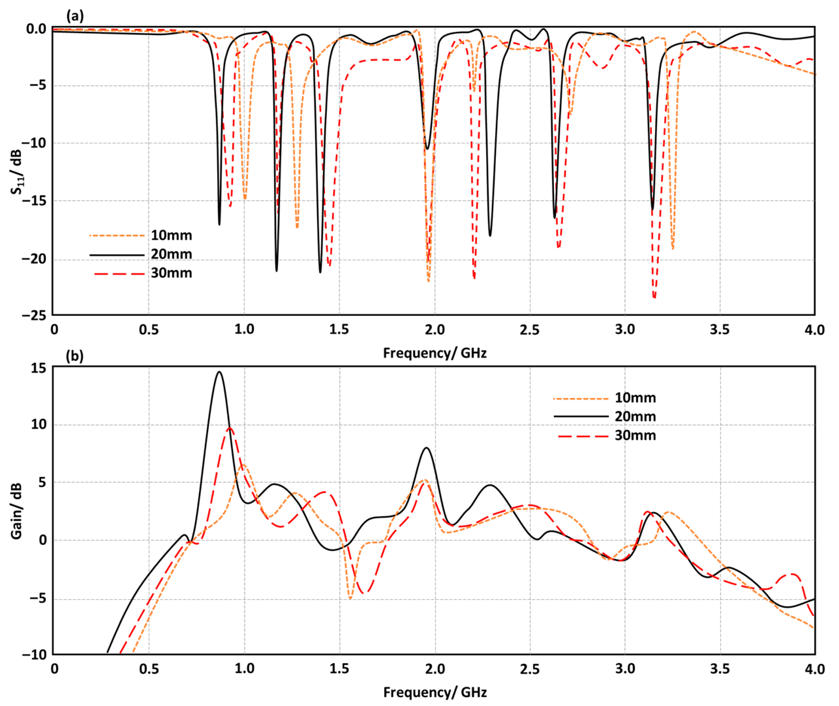
The proposed antenna is located underneath the proposed reflector structure, which is manufactured from a copper screen. The suggested reflector array is positioned beneath the suggested antenna at a specific separation distance. A parametric study is used to change the distance from 10 mm to 30 mm in steps of 10 mm in order to examine how this distance affects the antenna performance. Figure 8 illustrates the antenna performance for S11 and gain spectra. The optimal distance is considered 20 mm for the suggested reflector layer from the proposed antenna ground plane. The distance between the reflector and the antenna patch may result in observable slit effects on the antenna S11, as seen in Figure 8a. To achieve a gain enhancement of 14.8 dBi at 0.915 GHz, the antenna exhibits a notable change in gain as a result of this distance variation. As can be seen in Figure 8a, the evaluated S11 spectrum changes when the suggested reflector is added. This change is due to capacitive coupling effects on the patch structure. Figure 8b shows that the antenna works best when the boresight is 20 mm.

4.5. Unit Cell Number Effects

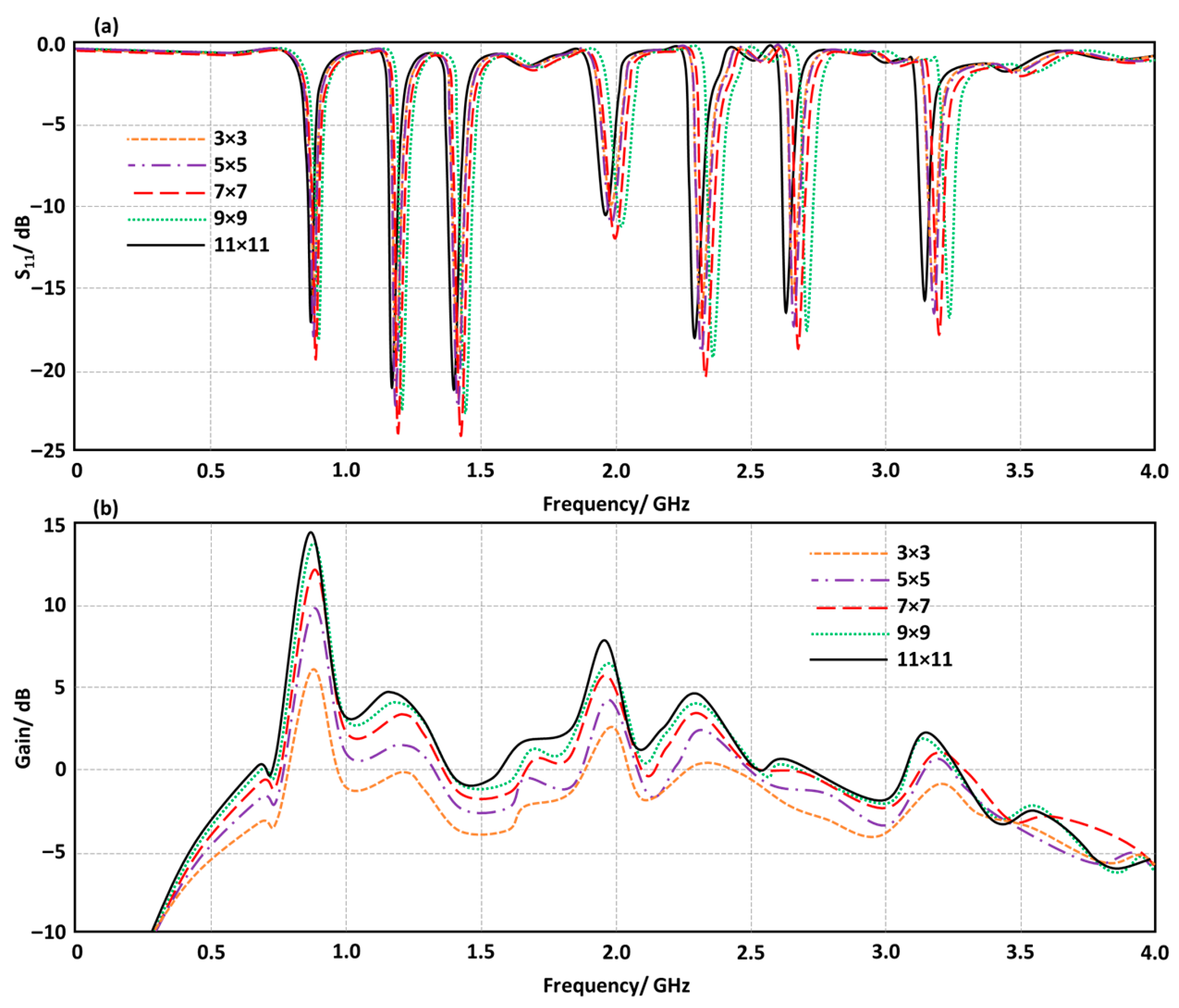
Changing the number of reflector unit cells puts the proposed antenna through another parametric evaluation. We changed the unit cell number in this part from 3 × 3 to 11 × 11 by using step two, which says to raise the unit cell number each time. Changing the number of unit cells does not impact the S11 parameters, but it does have several effects on the antenna gain, as shown in Figure 9. The recommended antenna, which is based on an 11 × 11 reflector, obtains a gain of 14.8 dBi at 0.915 GHz. It has a high front-to-back ratio and minimal side lobes of around −20 dBi and −23 dBi, respectively. It is found that the antenna works a little better with the 11 × 11 reflector size.

4.6. Ground Plane Size Effects

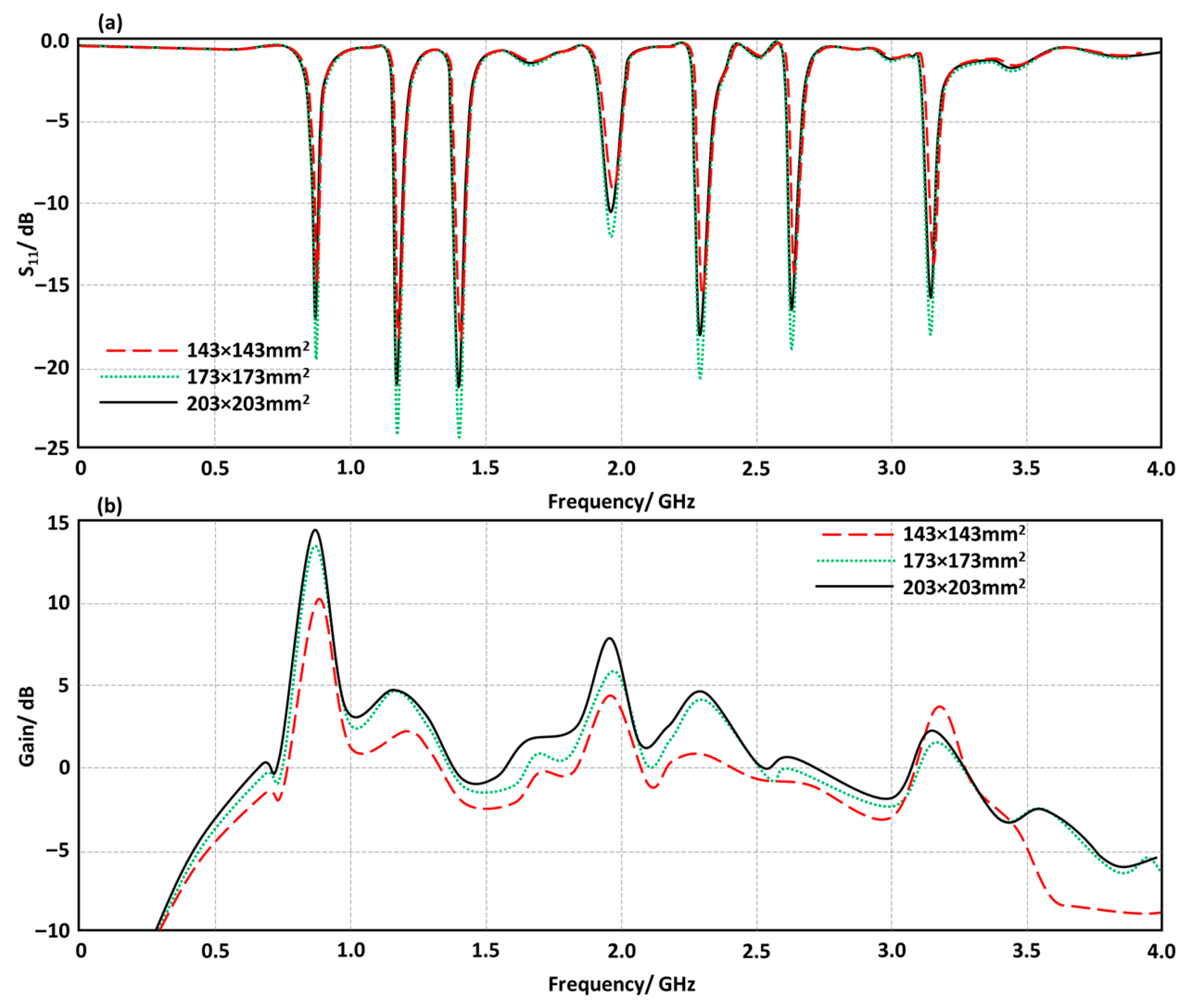
After the determination of the optimal antenna structure, the effects of varying the ground plane size on the antenna performance are discussed. We changed the ground plane size from 143 × 143 mm2 to 173 × 173 mm2 to 203 × 203 mm2 as seen in Figure 10 in terms of S11 and gain spectra. We found that after the second increase, the antenna shows no significant enhancements, as presented in Figure 10. Therefore, the authors decided to keep the design at a size of 173 × 173 mm2. It is found that there is no significant change in the antenna S11 due to a change in the ground plane size. However, the antenna gain is increased rapidly to 14.8 dBi after making the antenna ground plane size 173 × 173 mm2. No significant change is observed in the antenna gain when the ground plane size is increased to 203 × 203 mm2. It is important to mention that in all considered cases, we kept the MTM and reflector allocated in the same positions.

4.7. Antenna Beam Steering

The proposed antenna is evaluated by activating the PIN switches to correctly steer the beam, based on the performance attained. Table 1 demonstrates the antenna performance for strength, orientation, and operating frequency, as dictated by the binary coding switching state. The proposed antenna design exhibits dynamic beam steering functionality under the control of four PIN diodes (D1, D2, D3, and D4). This functionality facilitates the electrical modification of the radiation pattern. This method is particularly beneficial for wireless communication systems requiring rapid directional modifications and frequency alterations, such as cognitive radio, Internet of Things networks, and low-frequency beamforming applications. The starting configuration (0, 0, 0, 0) functions as the reference or default mode. The maximum gain is 14.8 dBi, and all diodes are off. Upon activation of diode D4, the beam is displaced marginally to the left by 5 degrees, the gain is reduced to 13.2 dB, and the frequency is adjusted to 0.913 GHz. The minor beam tilt indicates that the activation of a single edge diode induces an asymmetry that marginally modifies the current distribution and radiated phase throughout the aperture. The very slight decrease in gain indicates that, despite the guidance, the radiation efficiency is preserved. As additional diodes are selectively triggered, mainly D3 in conformation (0, 0, 1, 0), the beam direction becomes more visible. The antenna gain is reduced to 12.1 dBi, and the frequency escalates to 0.918 GHz when located at –13°. Such a design raises the antenna’s active electrical length and signifies that the construction is more unequal. When both D3 and D4 are involved, the formation (0, 0, 1, 1) results in important beam steering to −24°, yet the gain is reduced to 10 dB; the other values are summarized in Table 1. This example illustrates a prevalent trade-off in reconfigurable systems: the incorporation of supplementary reactive loads may increase beam deflection; however, it may also induce mutual coupling, destructive interference, and imbalanced current distributions that diminish radiated power. Activation of D2 and D3 as (0, 1, 1, 0) results in a pseudo-symmetric preparation. However, the proposed antenna gain is reduced rapidly to 8.3 dBi when the frequency increases to 0.916 GHz. Such a response indicates the antenna direction stays constant, although the produced gain is significantly reduced. Finally, switching D2, D3, and D4 to ON to reach the (0, 1, 1, 1) configuration realizes a beam steering to −20° with gain of 11.1 dBi, outperforming the prior setup at the frequency operation of 0.917 GHz.

5. Discussion

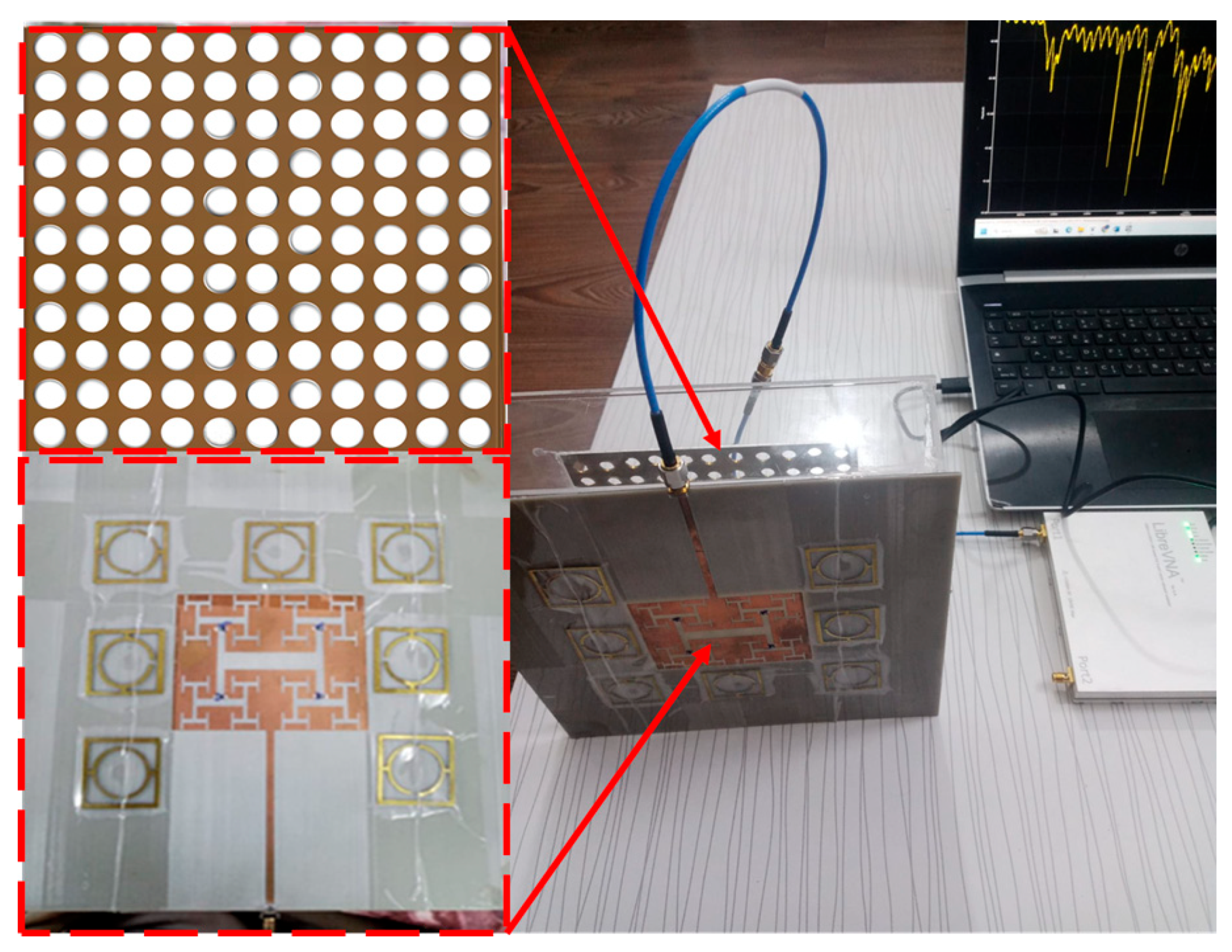
Once the ideal design was achieved, the suggested antenna was manufactured. With the help of the milling machine process, we were able to fabricate the antenna. As seen in Figure 11, the primary antenna component is constructed on a FR4 substrate with an 11 × 11 circular reflector screen.

5.1. Antenna Measurements

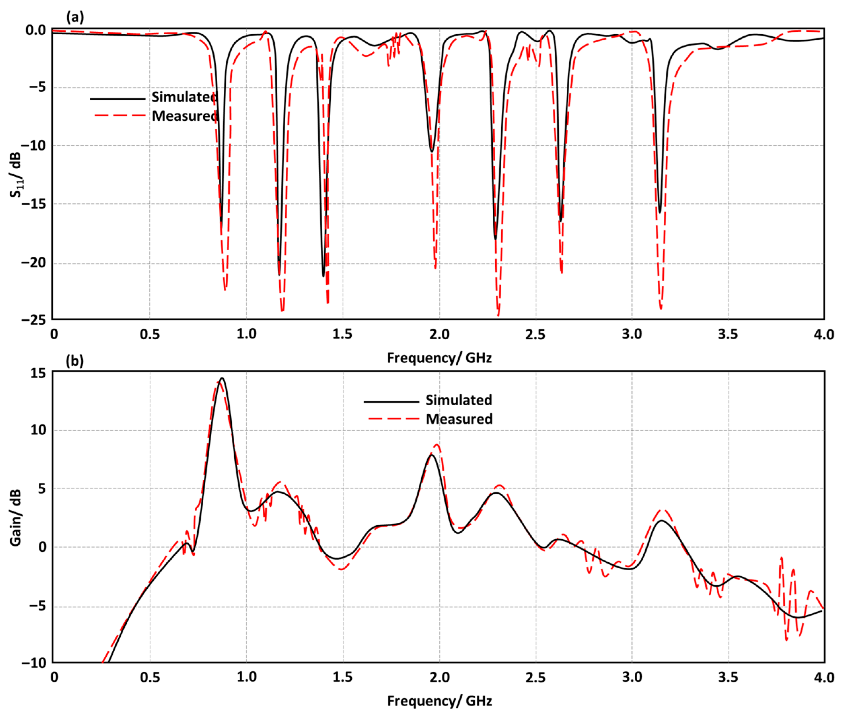
As shown in Figure 12, the antenna performance is experimentally measured using a VNA network analyzer from ZeenKo, Zhejiang Zhike Technology Co., Ltd., Hangzhou, China in terms of S11 and gain spectra. It is discovered that there is good agreement between the measured and simulated results.
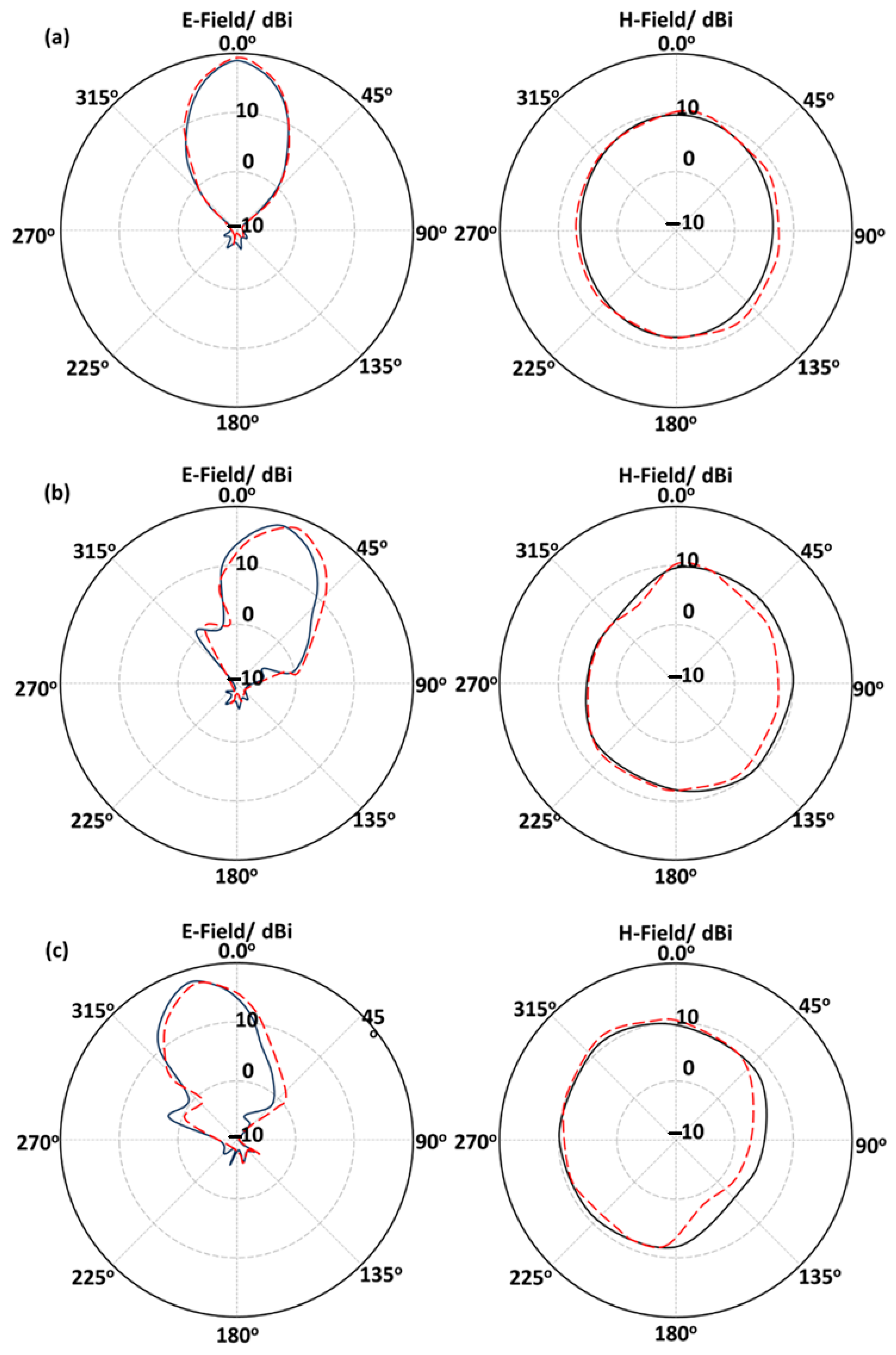
Subsequently, the radiation patterns shown in Figure 13 provide a comprehensive comparison between simulated and observed outcomes for three unique PIN diode switching configurations of a reconfigurable antenna. The PIN diodes integrated within the antenna, used for dynamically directing the radiation beam, exhibit varying biasing states in various setups. The spatial performance of the antenna is evaluated in two dimensions by plotting patterns in both the E-plane and H-plane across multiple reconfigurable modes. The antenna is in its baseline or omnidirectional configuration when all PIN diodes are off, as seen in Figure 13a. The primary lobe is positioned at about 0° in the E-plane, exhibiting a rather symmetric circular configuration in the H-plane, resulting in broadside radiation patterns. This indicates that without active steering, the antenna operates as a quasi-omnidirectional radiator. The primary lobe orientation, beamwidth, and side lobe levels exhibit remarkable consistency, with a striking alignment between the simulated and observed data in both the E- and H-planes. The remarkable degree of resemblance validates both the modeling assumptions and the manufacturing accuracy. The PIN diodes at the structure terminal are shown in Figure 13b, altering the reflection phases and current distribution over the surface. The resultant radiation pattern clearly indicates that the principal beam is displaced to one side, about ± 22° on the antenna radiation E-plane. Successful beam steering is shown by a significant deflection of the beam from the boresight. Nonetheless, the observed data reveal a little broadening of the beam and an imperceptible alteration in peak location. The antenna activates the other side of the structure by reversing the previously engaged PINs seen in Figure 13c.
The proposed antenna produces symmetric beam steering capability, as shown by the E-plane pattern changing in the opposite direction in Figure 13. Such a response is well shown by both simulated and experimental results, which reveal that the proposed antenna maintains azimuthal coverage with little disruption and that beam steering is mostly restricted to the E-plane. Beamforming arrays or wireless systems need coverage in various directions without mechanical redirection; hence, the antenna provides dual-direction beam steering by symmetric PIN diode switching. The validity of the simulations is verified by the symmetric beam steering directivity and gain, encompassing both the main lobe behavior and the features of side lobes, as well as pattern asymmetries.

5.2. Channel Performance Measurements

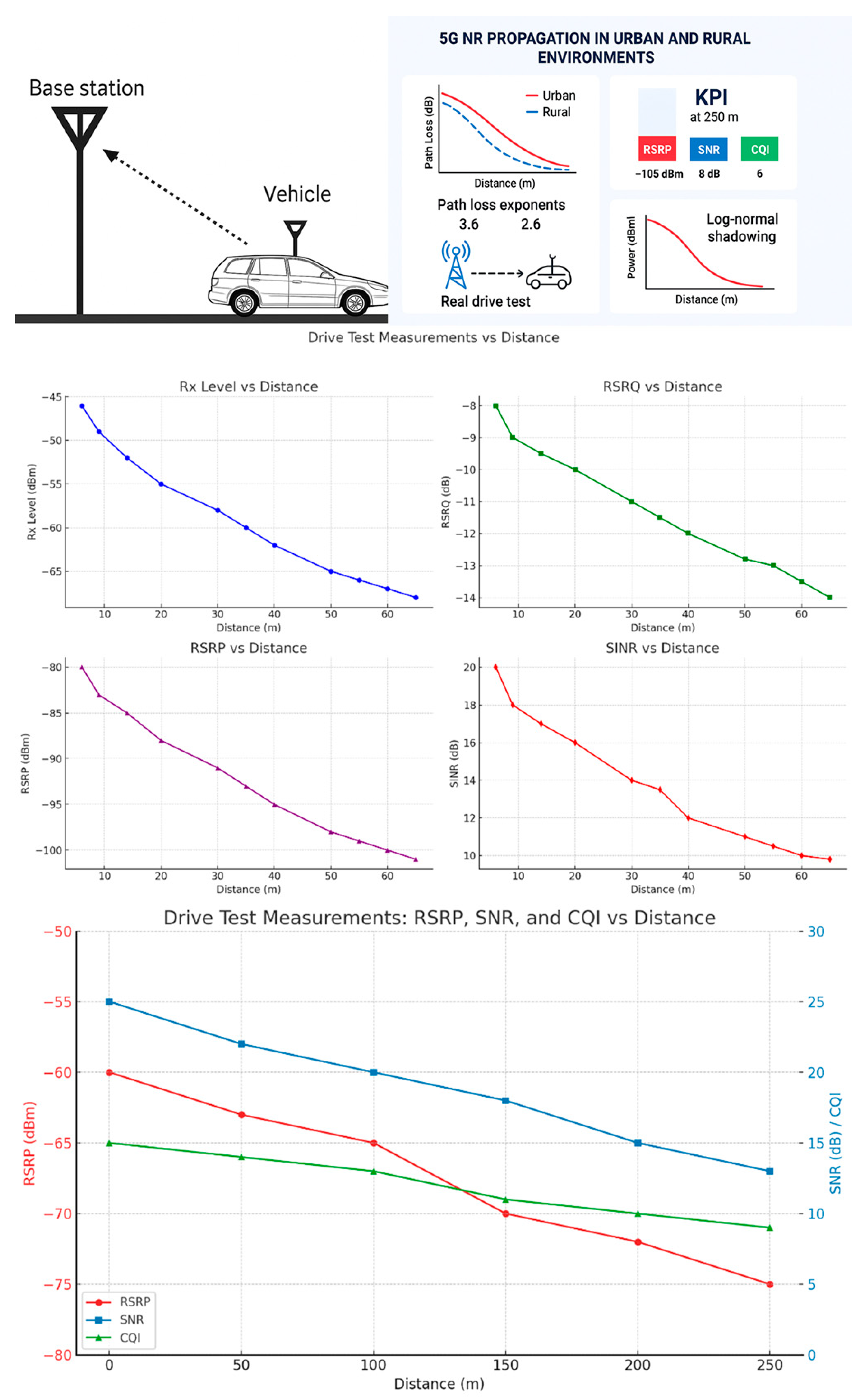
This section contains field data derived from drive testing performed to evaluate the proposed antenna design for 0.915 GHz-band radio transmissions in Baghdad, Iraq. Figure 14 illustrates data captured inside a cellular network, including many cells, each with a centrally located tower. The antenna tower at a certain location is located at a distance of 250 m from the proposed antenna, which is to be installed as a receiver on a vehicle for a driving test scenario. These driving test results for 5G coverage performance investigate the deterioration of three essential radio frequency (RF) parameters, namely RSRP, SNR, and CQI, as the distance from the transmission source increases. This test evaluates the practical performance for a 5G cellular system with a focus on channel capacity and data throughput over various propagation conditions. The obtained data demonstrate that RSRP values start at around −65 dBm and progressively decline as the user equipment travels away from the tower, reaching −105 dBm at a distance of 250 m. The evaluated SNR measures the influences of a modulation scheme and the accuracy of decoding. CQI, a composite statistic influenced by SNR and RSRP, denotes the overall quality of the connection. It aids the scheduler in choosing the most effective modulation and coding schemes (MCSs). The decline in connection quality is validated by the CQI values, which span from 15 (excellent) near the tower to 6 (moderate) at the most distant measurement site. The RSRP investigation, with its robust starting signal and minimal attenuation, suggests a distance-dependent standard route loss model. Nevertheless, RSRP diminishes with increasing distance owing to diffraction, ground reflection, and free space path losses. The transmitted signal decreases gradually after 50 m to reach −75 dBm and stays strong for reliable communication. The evaluated RSRP reaches the cell edges of high-speed throughput areas at 100 m, where the power decreases to −85 dBm. Based on the deployment frequency, Sub-6 GHz or mmWave, values above 150 m to 250 m vary between −95 dBm and −105 dBm, which are inadequate for a constant 5G NR connection. For low-latency or high-speed applications, such RSRP levels may be inadequate. A considered SNR value at the nearest distance from the transmitter allows the base station to apply higher-order modulation schemas such as 64-QAM or 256-QAM, later refining throughput. The performance of SNR and conservation effects are also considered. However, after 100 m, the SNR quickly decays, which is expected due to many environmental variables such as shadow fading caused by obstacles, interference from adjacent cells, background thermal noise, and heightened reflection and scattering from trees or buildings [6]. The network’s capacity to bear active decoding and modulation efficiency is significantly compromised when the SNR is reduced below 10 dB at 250 m, requiring a decrease to minor MCS levels or a change to the optimal cell [7]. CQI interpretation and system-level analysis provide valuable information for network designers and RF optimization experts. Such analysis encompasses beamforming and MIMO implementation, environmental modeling, the trade-off between coverage and capacity, threshold management, and cell planning. This driving test clearly demonstrates the degradation of 5G signal quality measures with increasing distance in a real-world deployment. The system’s decayed ability to uphold raised data rates is exposed by CQI, which determines the slow decrease in RSRP due to increasing route loss and realizes a rapid reduction in SNR, likely attributable to meddling and ambient noise. Confirming propagation models and expressing intelligent network policies are critical for confirming reliable recital in dynamic, user-intensive circumstances.
This study in Baghdad is compared with four different recent studies of the same concepts. Table 2 shows key features of comparison between the proposed work and other published works for both urban and rural plans. Through the environment understanding, we enable calculations of the path loss exponent (γ), which is found to be 3.6 for urban regions and 2.6 for rural regions, roughly corresponding with the values reported in [29]. Unlike [30], which depended on models, the results of the Baghdad study are more believable since they are solely based on actual driving tests. Furthermore, the evaluated SNR and CQI metrics prove improved radio performance and superior urban-focused assessments as in [31], while approaching the rural performance in [32], with an SNR of 8 dB and a CQI of 6 at 250 m distance. The use of log-normal shadowing and the explicit MSE-based optimization for γ estimation are methodological advantages lacking in several referenced studies, especially in [31,32]. Notably, by demonstrating actual propagation loss in Baghdad’s heterogeneous topography, the RSRP of −105 dBm at 250 m serves as a dependable reference model for future deployments. Ultimately, by combining analytical accuracy and empirical thoroughness, the proposed method offers a distinctive contribution to 5G propagation modeling in neglected regions.

6. Conclusions

This research illustrates the importance of high-performance antennas in practical wireless communication systems. Enhancing the circularly polarized microstrip patch antenna with an MTS reflector and EBG structure bridges the divide between empirical 5G NR propagation analysis and advanced antenna design. The proposed antenna design provides high gain with circular polarization and a compact profile for modern wireless communication applications, including 5G base stations. The antenna shows beam steering within a range of ±22° through four PIN switches. Practical driving tests are adopted with the aid of the proposed antenna to evaluate key performance indicators such as SNR, RSRP, and CQI in covering a circular area with a radius of 250 m. It is found from the obtained results that distinct propagation characteristics are achieved for both rural and urban environments to provide essential data required for accurate mobile network planning. Based on a log-normal shadowing model, large-scale fading effects are validated for the antenna operation under various channel conditions. Remarkable enhancements are obtained due to the enhanced antenna performance, which maintains strong signal integrity at the considered distances for both urban and rural areas. This work emphasizes the impact of antenna–channel co-design due to the direct impact of antenna performance on propagation capacities. A precise antenna design, with a performance unlike that observed in standard driving tests using commercial antennas, is achieved. This approach may improve data reliability, increase measurement precision, and extend coverage. Adaptive networks, enabled by beam steering integration, allow antennas to dynamically adjust radiation patterns to improve signal strength in real time. The research contributions include beam steering for adaptive coverage, empirical propagation modeling, validation of real-world performance, and the construction of a high-gain, circularly polarized antenna. A part of future research may be extended to combine massive MIMO, AI-assisted beamforming, and multi-band operation to improve coverage and spectral efficiency for several applications, including next-generation communication systems.

Author Contributions

Methodology, J.K.S.T.; Software, J.K.S.T.; Validation, J.K.S.T.; Investigation, O.B.; Writing—original draft, O.B. All authors have read and agreed to the published version of the manuscript.

Funding

This research was funded by International Applied and Theoretical Research Center (IATRC) with grant number [00A119].

Institutional Review Board Statement

Not applicable.

Informed Consent Statement

Not applicable.

Data Availability Statement

The original contributions presented in this study are included in the article. Further inquiries can be directed to the corresponding author.

Acknowledgments

The authors would like to express their thanks to Taha A. Elwi from the International Applied and Theoretical Research Center (IATRC) for his valuable support during the work of this research.

Conflicts of Interest

The authors declare no conflicts of interest.

References

  1. Jwair, M.H.; Elwi, T.A.; Khamas, S.K.; Farajidavar, A.; Ismail, A.B. Circularly shaped metamaterial fractal reconfigurable antenna for 5G networks. Iraqi J. ICT 2023, 6, 65–75. [Google Scholar] [CrossRef]
  2. Kamil, A.S.; Misran, N.; Oleiwi, T.A. Demystifying 5G: The Strategic Evolution to Massive MIMO for Enhanced Network Capacity and Economic Gains. Power Syst. Technol. 2025, 49, 1086–1120. [Google Scholar] [CrossRef]
  3. Balanis, C.A. Modern Antenna Handbook; Wiley, John & Sons, Inc.: Hoboken, NJ, USA, 2008. [Google Scholar]
  4. Elwi, T.A.; Al-Rizzo, H.M. Fresnel lenses based on nano shell-silver coated silica array for solar cells applications. Prog. Electromagn. Res. B 2011, 32, 263–282. [Google Scholar] [CrossRef]
  5. Yang, F.R.; Ma, K.P.; Qian, Y.; Hoh, T. Uniplanar compact photonic band gap (UC-PBG) structure and its applications for microwave circuits. IEEE Trans. Microw. Theory Tech. 1999, 47, 1509–1514. [Google Scholar] [CrossRef]
  6. Al-Saegh, A.M.; Taher, F.; Elwi, T.A.; Alibakhshikenari, M.; Virdee, B.S.; Livreri, P.; Al-Jumaily, A.; Sree, M.F.A.; Kouhalvandi, L.; Hassain, Z.A.A.; et al. AI-based investigation and mitigation of rain effect on channel performance with aid of a novel 3D slot array antenna design for high throughput satellite system. IEEE Access 2024, 12, 29926–29939. [Google Scholar] [CrossRef]
  7. Abdulkareem, Z.J.; Hamad, T.K.; Elwi, T.A. Reconfigurable metasurface based on graphene micro-ribbons for beam focusing applications. J. Theor. Appl. Phys. 2025, 19. [Google Scholar] [CrossRef]
  8. Elwi, T.A.; Al-Rizzo, H.M.; Bouaynaya, N.; Hammood, M.M.; Al-Naiemy, Y. Theory of gain enhancement of UC–PBG antenna structures without invoking Maxwell equations: An array signal processing approach. Prog. Electromagn. Res. B 2011, 34, 15–30. [Google Scholar] [CrossRef]
  9. Zaal, R.M.; Kamal, N.N.; Ahmed, M.A.; Al-Sultani, S.H.G.; Bin, S.K.; Oleiwi, T.A. Direct Antenna Beam Squint Correction Using AI-Equalization Strategy for 3D MIMO Array System. In Proceedings of the 2024 4th International Conference on Artificial Intelligence and Signal Processing (AISP), Vijayawada, India, 26–28 October 2024; pp. 1–5. [Google Scholar] [CrossRef]
  10. Azeez, A.R.; Al-Sharify, T.A.; Abdullah, O.; Salam, Z.; Al-khaylani, H.H.; Oleiwi, T.A. High Gain Tapered Slot Antenna Based on Offset Radiation Characteristic for 5G Wireless Applications. In Proceedings of the 2024 4th International Conference on Artificial Intelligence and Signal Processing (AISP), Vijayawada, India, 26–28 October 2024; pp. 1–5. [Google Scholar] [CrossRef]
  11. Al-Saegh, A.M.; Elwi, T.A. Direct extraction of rain-induced impairments on satellite communication channel in subtropical climate at K and Ka bands. Telecommun. Syst. 2020, 74, 15–25. [Google Scholar] [CrossRef]
  12. Al-Saegh, A.M.; Elwi, T.A.; Abdullah, O.A.; Sali, A.; Aljumaily, A.H.J. Rainfall Effect on Satellite Communications in Mosul at Frequencies above 10 GHz. In Proceedings of the 2021 7th International Conference on Space Science and Communication (IconSpace), Selangor, Malaysia, 23–24 November 2021; pp. 318–322. [Google Scholar] [CrossRef]
  13. Al Naiemy, Y.; Abdulateef, A.N.; Hamad, A.R.; Ismael, M.S.; Ruthramurthy, B.; Elwi, T.A.; Nagy, L.; Zwick, T. A Further Realization of Binary Genetic Algorithm to Design a Dual Frequency Band Rectenna for Energy Harvesting in 5G Networks. DJES 2025, 18, 203–214. [Google Scholar] [CrossRef]
  14. Rashid, S.A.; Audah, L.; Hamdi, M.M.; Abood, M.S.; Abbas, G.R.; Mohammed, B.S.; Elwi, T.A.; Khan, S.; Virdee, B.S.; Krasniqi, A.; et al. Delay-minimization and back-off aware Q-learning with advanced bio-inspired CH selection for multi-hop communication in vehicular ad-hoc networks. Radio Sci. 2025, 60, e2024RS008165. [Google Scholar] [CrossRef]
  15. Hamad, A.R.; Al-Adhami, A.; Elmunim, N.A.; Alibakhshikenari, M.; Virdee, B.; Hamad, H.S.; Jayanthi, R.; Mariyanayagam, D.; Lubangakene, I.; Kumar, S.; et al. Rectenna design optimized by binary genetic algorithm for hybrid energy harvesting applications across 5G sub-6GHz band. Radio Sci. 2025, 60, e2024RS008154. [Google Scholar] [CrossRef]
  16. Attrah, Z.; Al-Sharify, M.T.; Al-Janabi, A.F.; Yetkın, G.Ö.; Oleiwi, T.A.; Al-Khaylani, H.H. Wideband MIMO 5G Antennas for Handset Devices. In Proceedings of the 2024 4th International Conference on Artificial Intelligence and Signal Processing (AISP), Vijayawada, India, 26–28 October 2024; pp. 1–5. [Google Scholar] [CrossRef]
  17. Taher, F. Novel antenna-based metamaterial structure with Slotted and parastic patches for 5G- sub 6GHz applications. J. Adv. Res. Appl. Sci. Eng. Tech. 2025, 65, 143–152. [Google Scholar] [CrossRef]
  18. Thella, R.K.; Sabah, A.; Kumar, J.; Al-Janabi, M.A.; Oleiwi, T.A.; Peddakrishna, S. E-Shaped Inspired 2.4GHz Compact Microstrip Patch Antenna. In Proceedings of the 2024 4th International Conference on Artificial Intelligence and Signal Processing (AISP), Vijayawada, India, 26–28 October 2024; pp. 1–4. [Google Scholar] [CrossRef]
  19. Taher, F. Design of Offset Radiation Tapered Slot Antenna. J. Adv. Res. Appl. Sci. Eng. Tech. 2025, 64, 37–46. [Google Scholar] [CrossRef]
  20. Bashar, B.S.; Al-Sharify, T.A.; Rhazali, Z.A.; Misran, H.; Ismail, M.M.; Oleiwi, T.A. Miniaturized Metamaterial Antenna for 5.7GHz Services. In Proceedings of the 2024 4th International Conference on Artificial Intelligence and Signal Processing (AISP), Vijayawada, India, 26–28 October 2024; pp. 1–5. [Google Scholar] [CrossRef]
  21. Taher, F. Novel Reconfigurable Fractal Antenna Design for Modern Communication Systems. J. Adv. Res. Appl. Sci. Eng. Tech. 2025, 64, 47–57. [Google Scholar] [CrossRef]
  22. Bashar, B.S.; Mejbel, B.G.; Rhazali, Z.A.; Misran, H.; Ismail, M.M.; Oleiwi, T.A. Reconfigurable Antenna Based CLRH Inclusions for 5G Wireless Networks. In Proceedings of the 2024 4th International Conference on Artificial Intelligence and Signal Processing (AISP), Vijayawada, India, 26–28 October 2024; pp. 1–5. [Google Scholar] [CrossRef]
  23. Ali, M.M.; Segura, E.M.; Elwi, T.A. Advancements in Ku Band Resonator Composite Right/Left-Handed (CRLH) Metamaterials: Design, Analysis, and Applications. J. Eng. Sustain. Dev. 2025, 29, 184–189. [Google Scholar] [CrossRef]
  24. Bashar, B.S.; Mejbel, B.G.; Rhazali, Z.A.; Misran, H.; Ismail, M.M.; Oleiwi, T.A. Design of Metasurface Antenna for 5G Applications. In Proceedings of the 2024 4th International Conference on Artificial Intelligence and Signal Processing (AISP), Vijayawada, India, 26–28 October 2024; pp. 1–4. [Google Scholar] [CrossRef]
  25. Miligy, A.F.; Taher, F.; Elwi, T.A.; Abdelaleim, M.; Sree, M.F.A.; Fatah, S.Y.A. Broad Band 2×4 Horn Antenna Array for High Power Microwave (HPM) Systems Application. J. Adv. Res. Appl. Sci. Eng. Tech. 2025, 64, 1–17. [Google Scholar] [CrossRef]
  26. Thella, R.K.; Muqdad, Z.S.; Kumar, J.; Ismael, M.S.; Hussein, H.; Oleiwi, T.A. Compact Omni-Directional 2.4GHz Antenna for ISM Band Applications. In Proceedings of the 2024 4th International Conference on Artificial Intelligence and Signal Processing (AISP), Vijayawada, India, 26–28 October 2024; pp. 1–4. [Google Scholar] [CrossRef]
  27. Al-Hadeethi, S.T.; Elwi, T.A.; Ibrahim, A.A. A Printed Reconfigurable Monopole Antenna Based on a Novel Metamaterial Structures for 5G Applications. Micromachines 2023, 14, 131. [Google Scholar] [CrossRef]
  28. Alibakhshikenari, M.; Virdee, B.S.; Elwi, T.A.; Lubangakene, I.D.; Jayanthi, R.K.R.; Al-Behadili, A.A.; Hassain, Z.A.A.; Ali, S.M.; Pau, G.; Livreri, P.; et al. Design of a Planar Sensor Based on Split-Ring Resonators for Non-Invasive Permittivity Measurement. Sensors 2023, 23, 5306. [Google Scholar] [CrossRef] [PubMed]
  29. Al-khaylani, H.H.; Elwi, T.A.; Ibrahim, A.A. Optically Remote Control of Miniaturized 3D Reconfigurable CRLH Printed Self-Powered MIMO Antenna Array for 5G Applications. Micromachines 2022, 13, 2061. [Google Scholar] [CrossRef]
  30. Hussein, H.; Atasoy, F.; Elwi, T.A. Miniaturized Antenna Array-Based Novel Metamaterial Technology for Reconfigurable MIMO Systems. Sensors 2023, 23, 5871. [Google Scholar] [CrossRef]
  31. Ajewole, B.; Kumar, P.; Afullo, T. A Microstrip Antenna Using I-Shaped Metamaterial Superstrate with Enhanced Gain for Multiband Wireless Systems. Micromachines 2023, 14, 412. [Google Scholar] [CrossRef] [PubMed]
  32. Islam, T.; Hussain, D.; Alsunaydih, F.N.; Alsaleem, F.; Alhassoon, K. Designing a Novel Hybrid Technique Based on Enhanced Performance Wideband Millimeter-Wave Antenna for Short-Range Communication. Sensors 2024, 24, 3219. [Google Scholar] [CrossRef] [PubMed]
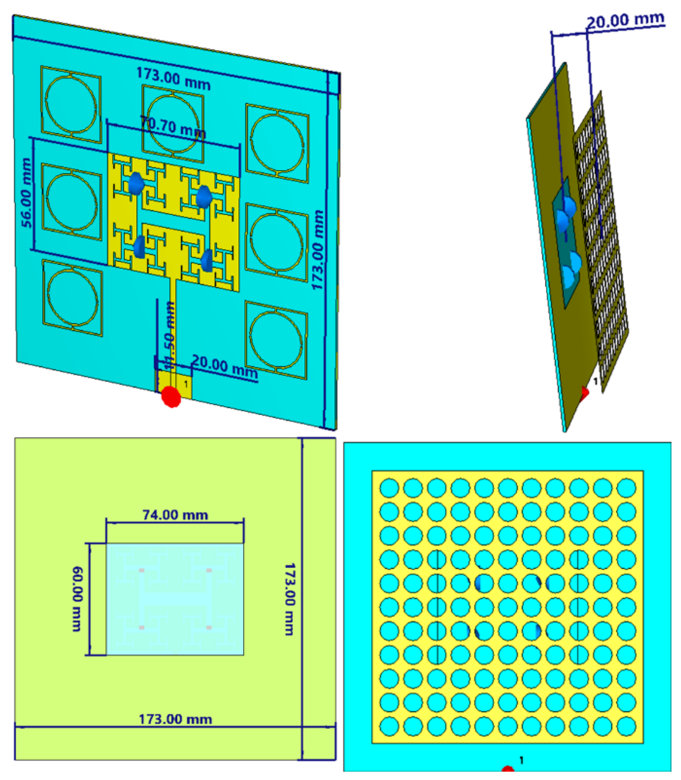
Figure 1. Antenna geometry based on patch structure in the front view, side view, and back view.
Applsci 15 10692 g001
Figure 2. Antenna reflector geometry.
Applsci 15 10692 g002
Figure 3. Ray tracing analysis.
Applsci 15 10692 g003
Figure 4. The proposed unit cell reflection response.
Applsci 15 10692 g004
Figure 5. Antenna performance without reflector: (a) S11 spectra and (b) gain spectra.
Applsci 15 10692 g005
Figure 6. Antenna performance with ground plane effects: (a) S11 spectra and (b) gain spectra.
Applsci 15 10692 g006
Figure 7. The proposed antenna MTM’s effects on the antenna: (a) S11 spectra and (b) gain spectra.
Applsci 15 10692 g007
Figure 8. A parametric study on the reflector structure location: (a) S11 and (b) gain spectra.
Applsci 15 10692 g008
Figure 9. A parametric study on the reflector unit cell number: (a) S11 and (b) gain spectra.
Applsci 15 10692 g009
Figure 10. A parametric study on the ground plane size: (a) S11 and (b) gain spectra.
Applsci 15 10692 g010
Figure 11. The fabricated antenna protype.
Applsci 15 10692 g011
Figure 12. Measured results: (a) S11 and (b) gain spectra.
Applsci 15 10692 g012
Figure 13. The measured radiation patterns at 0.915 GHz: (a) at [0, 0, 0, 0] PIN switching configuration, (b) at [0, 0, 1, 1] PIN switching configuration, and (c) at [1, 1, 0, 0] PIN switching configuration. Note: The solid black line represents simulations, and the red dashed line represents measurements.
Applsci 15 10692 g013
Figure 14. Channel performance measurements based on the proposed drive test scenario.
Applsci 15 10692 g014
Table 1. The evaluated antenna performance with different switching scenarios.
Status for D1, D2, D3, D4Gain/dBDirection/Deg.Frequency/GHz
0, 0, 0, 014.800.915
0, 0, 0, 113.2−50.913
0, 0, 1, 012.1−130.918
0, 0, 1, 110−24 0.910
0, 1, 0, 012.6−70.911
0, 1, 0, 114−30.912
0, 1, 1, 08.300.916
0, 1, 1, 111.1−200.917
Table 2. A comparison study between the proposed work and other published results.
ParameterProposed Work (Baghdad Drive Test)Urban 5G Study—CairoRural LTE Drive Test—UKPath Loss Study—IndiaShadowing Analysis—Germany
EnvironmentUrban and Rural (Baghdad)UrbanRuralSuburbanUrban
Technology5G NR5G NRLTELTE5G NR
Frequency BandSub-6GHzSub-6GHz1800 MHz2100 MHz3.5 GHz
Measurement MethodReal Drive TestSimulation + Drive TestReal Drive TestSimulationReal Drive Test
Distance Range (m)0–2500–5000–10000–3000–200
Path Loss Exponent (Urban)3.63.9N/A3.53.8
Path Loss Exponent (Rural)2.6N/A2.72.8N/A
RSRP at 250 m (dBm)−105−110−100−102−108
SNR at 250 m (dB)86975
CQI at 250 m65765
Shadowing Model UsedLog-NormalLog-NormalLog-NormalOkumura–HataLog-Normal
MSE Optimization✔ Yes (for γ estimation)✘ Not applied✔ Yes✘ Not used✔ Yes
Key ContributionReal 5G data + γ derivation5G simulation validationEmpirical rural modelModel tuningShadowing variation over time
ReferenceThis paper[6][9][11][12]
Disclaimer/Publisher’s Note: The statements, opinions and data contained in all publications are solely those of the individual author(s) and contributor(s) and not of MDPI and/or the editor(s). MDPI and/or the editor(s) disclaim responsibility for any injury to people or property resulting from any ideas, methods, instructions or products referred to in the content.