Abstract
This work proposes a novel design configuration for an elasto-poro-hydrodynamic damper (EPHD damper) that consists of an imbibed, soft, elastic, porous material enclosed by a rubber membrane. The core innovation lies in the device’s ability to collect and re-imbibe expelled fluid during decompression, ensuring potential functionality and durability across repetitive loading cycles. Damping is achieved through the synergy of three mechanisms: friction of the membrane and of the piston with solid boundaries, squeeze flow inside the porous layer, and compression of the poro-elastic structure. The EPHD damper’s behavior was evaluated both theoretically and experimentally through quasi-static, low-speed compression tests, with dynamic evaluation being reserved for future work. A numerical model successfully validated stress-deformation behavior against experimental data, with a simplified analytical model providing a good approximation. The study also identifies that the piston–membrane friction coefficient significantly influences the EPHD damper’s performance. These findings provide a valuable framework for optimizing the design and expanding its potential application to repetitive damping systems.
1. Introduction
Researchers have been trying to find new methods for shock protection with good damping capacity and short response time. Squeeze flows represent one possible solution with applications in dynamically loaded journal bearings, squeeze film dampers, rheometers, and human joints. Coupling a thin elastic bladder with a fluid enables expulsion on loading and re-imbibition on unloading, yielding a device for repetitive shock protection.
An extensive analysis of shock and vibration damping devices shows that there is a wide variety of design solutions, based on different mechanisms or physical processes. Damping can be obtained by energy dissipation through external or internal friction forces. External friction forces depend on the contact surfaces and can be produced by Coulomb friction (dry friction) or by viscous friction. Internal friction forces are also of viscous nature, being defined by hysteresis phenomenon. Another classification of damping solutions is made according to the type of loading: cyclic or impact. The latter case includes the so-called single-use shock absorbers, which are destroyed after the impact.
Over time, various design solutions of dampers with different attenuation mechanisms or materials have been investigated: viscoelastic, hydraulic, elasto-pneumatic, hydro-elastic, or hydro-pneumatic. Among these categories, pneumatic or hydro-elastic dampers, which use both the effect of fluid squeeze and viscoelastic deformation, are considered solutions of interest for the present paper.
Elastomeric materials (rubber) are widely used for shock absorbers due to properties such as high inherent damping, deflection capacity, and energy storage. The combination of viscous and elastic properties makes the rubber a unique material. Most rubber bags are susceptible to elastic instability, but the toroidal one is an exception and has good resistance to buckling.
MacNeal and Loisch [1] presented one of the first studies on the usage of filament wound toroids (toroidal rubber bladder reinforced with high-strength structural filaments) as pneumatic dampers for space applications (e.g., landing gears for re-entry capsules). The results proved that light gases, like helium, should be used to increase specific energy absorption. For increased efficiency, the rubber was reinforced with Nylon fibers.
In recent years, important research efforts were directed towards bellow rubber dampers, mainly developed for trucks, buses, and railway vehicles. Known as air springs, they are composed of a minimum of two bellows in series. They present low natural frequency independent on load and an excellent isolation performance for high-frequency vibration. Controlling the intake and exhaust valves allows air springs to adjust their working parameters (stiffness, deformation, etc.), ensuring optimal handling for varying conditions.
Han et al. [2] presented a novel three-dimensional isolation bearing combining a single bellow air spring with a friction pendulum system. It was designed to isolate horizontal and vertical ground motions simultaneously for large-span spatial structures. The spring was loaded axially and was mounted inside a large roller bearing to allow simultaneous rotation of the support to a fixed base. The air pressure was controlled, and the radial deformation of the spring was limited by the Inner radius of the bearing. The hysteretic performance of the device increased linearly with air pressure and the experiments proved good durability. Similarly, Yin et al. [3] presented an air spring dynamic vibration absorber, which offered good performance in a limited structural space. Two pressurized springs mounted in series, separated by an absorbing mass were used. The absorbing mass, a rigid body, was used to change the modal response. The two air springs were linked by a pipe with an adjustable orifice, allowing gas flow, thus influencing the stiffness and damping capacity of the device. Cheng et al. [4] explored an air spring device with a deformation principle different to the one presented by Yin et al. [3]. The bellow was surrounded radially by a constraining sleeve, and, during loading, the air springs deformed axially with an inferior arc, which curled over along a guide seat. During axial loading, the stiffness of the bellows increased with their design change.
In parallel, there have been efforts to explore the damping potential of rubber springs filled with liquids. Moss et al. [5] developed a new solution of hydro-elastic damper that was used to study the effects of fluid expulsion. Their model consisted of two parallel plates, separated by a Newtonian fluid enclosed by a thin membrane of natural rubber. Most of the energy was dissipated due to fluid viscous friction during compression. The authors studied the system only for the case of compression by impact (single usage). Krassnokutski et al. [6] continued the work by performing a series of experiments that involved monitoring pressures at three different points on the radius of the disc.
The damping capacity of elastic, soft, porous materials imbibed with liquids has been studied by Pascovici, who named this mechanism XPHD, and his co-workers during the last two decades. One of the first analyses of a squeeze process with deformable porous layers that accounted for permeability variation was presented in [7]. This analysis was made for two configurations: sphere-on-plane and disk-on-plane, respectively. An optimum porosity for the sphere-to-plane configuration loaded with constant force was also predicted.
Pascovici et al. [8] analyzed theoretically the squeeze process for circular and rectangular plates under impact, considering both limited flow model and extended flow model for circular cases. They derived compact equations for the load capacity variation with porous layer thickness [9].
Complementary experiments using in-house test rigs (a falling ball, horizontal gas gun, pendulum, and universal tester) evaluated the load carrying capacity and damping. Alongside this, porosity and permeability evaluation for various materials and fluid was performed. Highly porous materials (porosity > 80%) such as textiles, foams, and composites were tested both at constant compression and under impact.
Studies also highlighted the impact damping potential of open [10,11] (imbibed porous layers without an enclosing membrane) or encapsulated [12,13] “damping cells” (porous material wrapped around with a thin, easily tearable membrane that seals the fluid inside). The intended applications included protective equipment, such as an additional damping layer that exists in protection helmets and other protective equipment for sports.
However, a critical research gap remains: the development of a durable, repeatable, and efficient damping/attenuating device. This study introduces a novel damping device that addresses this aspect by utilizing the ex-poro-hydrodynamic mechanism (XPHD) for repetitive loading applications. The context of our study is to extend the previously tested solution [14] that implies energy dissipation over a small displacement by means of reaction forces generated by squeezing a fluid between two disks. The flaws of this solution are related to the radial expansion of the elastic membrane, which makes it vulnerable to possible contact with sharp objects, and the cylindrical membrane used requires a special mold; any dimensional modification of it requires the redesign and execution of a new mold.
The XPHD mechanism, previously studied for single-use applications, involves squeezing a fluid from a highly compressible porous structure. As the porous material is compressed, the flow resistance through its internal structure generates a lifting force. This effect, combined with the porous material’s deformation, creates a powerful damping effect. Material permeability, which is a function of porosity variation during compression, increases resistance to flow. This effect is additional to the response of solid matrix. The same mechanism can be found in articular cartilages [15,16].
The novelty of our design lies in enclosing the imbibed porous material with an elastic flat membrane, which allows the expelled fluid to be collected and re-imbibed during decompression. This crucial feature enables the device to handle repetitive loadings without the need for manual fluid refill or replacement.
The aim of this investigation is to evaluate experimentally and theoretically a novel damping device based on imbibed, soft, porous materials enclosed by an elastic membrane that offers the possibility of repetitive loading applications. To establish a clear understanding of the underlying mechanisms and parameter sensitivities of the new device, the present study focuses on quasi-static, low-speed compression tests, which allow precise characterization of the compression of the poro-elastic structure, squeeze-flow, and its effects on the deformation of elastic membrane. A series of exploratory tests were performed in dynamic conditions, but these results will be included in a future paper. Theoretical models are proposed and evaluated to provide useful information for optimizing the functional and geometrical parameters of the EPHD damper. Our findings are compared and discussed in the context of earlier work to demonstrate the device’s enhanced performance and durability.
2. EPHD-Damper Design Configuration
2.1. The Device
The elasto-poro-hydrodynamic damper (EPHD damper—Figure 1) consists of a rigid base (cup) provided with a cylindrical cavity in which an imbibed porous layer is placed, a rubber membrane that encloses the cavity, and a clamping collar that ensures the sealing during compression and guides a stepped moving piston.
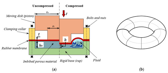
Figure 1.
(a) Design configuration of the newly EPHD damper: left—uncompressed, right—compressed; (b) expelled volume—half toroidal.
When the imbibed porous material is compressed, the fluid is squeezed out from the central area, filling the peripheral area of the cup, forming an annular inflated region (half toroidal shape). The membrane seals the cavity and collects the expulsed fluid. During the return stroke of the piston, the membrane recovers the flat form, ensuring the re-imbibition (pumping back) of the fluid in the porous layer. Based on this design, an experimental device was manufactured (Figure 2).
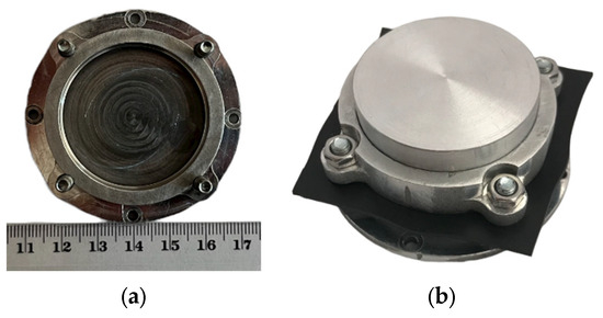
Figure 2.
Image of the manufactured model: (a) rigid base; (b) assembly of the EPHD damper.
The damping effect incorporates three mechanisms, which contribute to an overall damping capacity/transmitted force:
- Elastic deformation of a rubber membrane;
- Squeeze flow inside the porous layer;
- Compression of the deformable porous layer.
For proper operation of the EPHD damper, some important features were considered during the design process. The outer recess of the piston must provide enough space to allow the membrane to deform freely and to collect the quantity of expulsed fluid (at maximum compression), without affecting its behavior.
2.2. Materials
The convenient solution is a soft fibrous 3D textile (S3D), composed of two outer layers and a middle, connecting layer, previously used in experiments performed by our team [9,12,13]. Its initial thickness is h0 = 6.4 mm, and the corresponding porosity is ϕ0 = 0.9.
The compression response of S3D materials is relatively strong and was analyzed in various papers, both experimentally [13,17,18,19] and numerically [20,21]. S3D textiles have great energy absorption capabilities due to buckling and bending of the fibrous structure.
When subjected to squeeze, the resistance under compression of porous materials, in general, is enhanced upon imbibition. For this study, two Newtonian fluids were selected: glycerin 98% and SAE 5W30 oil.
The rubber membrane must meet several requirements: high elasticity, no plasticity, high fatigue resistance (especially to multiple stretching), and waterproof. After preliminary tests with various elastic membranes, a natural rubber (°ShA 40 ± 5) of thickness t = 1 mm was retained for static experiments.
3. Quasi-Static Tests
3.1. Operating Conditions
The EPHD damper was subjected to quasi-static tests, carried out on two different test rigs. The multifunctional test rig CETR-UMT2 (Figure 3) was used for low compression forces, while a Zwick/Roell Z010 TN universal testing machine was used for compression with higher forces. All the tests were performed at quasi-constant room temperature (≈20–24 °C). A low compression speed of 0.5 mm/s was used throughout the experimental evaluation.
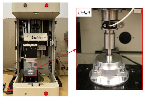
Figure 3.
EPHD damper during a test on multifunctional test rig CETR-UMT2.
Variation of force with displacement was recorded. To minimize the experimental errors, multiple tests (3-5-10) on the same specimen and on distinct specimens were performed.
Discs of S3D materials with a radius of ro = 20 mm were placed in the cylindrical cavity, filled with fluid by weighing. The quantity of fluid corresponds to the volume occupied by the pores inside the porous layer (≈7.79 mL):
- For tests with imbibed porous layer, the fluid mass was ≈9.15 g of glycerin and ≈6.28 g of 5W30 oil, respectively.
- For tests without porous layer (only fluid and rubber), the fluid mass was ≈9.63 g of glycerin and ≈6.62 g of 5W30 oil, respectively.
No visible leakage was observed during or after the experiments.
The complete imbibition of the porous material took 5 to 10 min and required gentle compressions to expel out the air bubbles from the material. The assembling of the EPHD damper is completed after the membrane is added and clamping collar is secured. To ensure a plane surface between the membrane and the piston, the membrane is pre-stretched: the axis of its holes is positioned on a diameter 2 mm smaller than the axis of the holes on the rigid base (Figure 1), allowing it to stretch with ≈1 mm/radius. For all the experiments, a clamp torque of ≈1 N·m was ensured.
3.2. Results
The stress-relative deformation variation for S3D material was analyzed for ten consecutive tests performed on the same S3D specimen (Figure 4a). To evaluate the intensity of the compression, the stress values presented on the graph are obtained using Equation (1):
where F is the measured force, and Ac is the contact area (highlighted in Figure 4a).
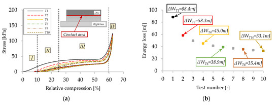
Figure 4.
Stress-relative compression variation: (a) compression behavior of the dry S3D for 10 consecutive tests; (b) energy loss for 10 consecutive tests on dry S3D.
Relative compression is expressed in terms of the porous layer and membrane thickness and is calculated using Equation (2):
where h0 is initial thickness of the porous material, t is the thickness of the rubber membrane, and h is the thickness of the compressed porous material (Figure 1).
These results confirm the observations reported in similar studies [18] that 3D spacer textiles exhibit four different phases under compression: (I) initial stage, defined by low stress values (due to the compression of loose ends of external faces and middle layer); (II) elastic stage governed by an increase in compression stress; (III) plateau stage with constant stress-relative deformation variation; and (IV) densification stage defined by a fast increase in stress values, resulting in high stiffness. In our experiments, the compression surface defined by the piston is smaller than the diameter of the S3D samples. In this case, the material around the piston generates additional resistance during compression, resulting in higher stresses.
Compression behavior of the porous material is presented in Figure 4a. In this case, relative compression is calculated using Equation (2), considering t = 0 mm. From Figure 4a, one can determine energy losses through hysteresis for dry S3D material. The energy loss calculation is based on the area of the hysteresis loop using numerical integration (trapezoidal method).
The energy loss calculated for the second test is 34% smaller than the one calculated for the first test (ΔWT1 = 88.4 mJ and ΔWT2 = 58.3 mJ). For more than two tests, it can be observed in Figure 4b that the energy loss variation decreases from 23% between Test 2 and Test 4, up to 7% between Test 8 and Test 10. Thus, one can say that indeed the S3D material stabilizes at lower stress values but is constant over time, after the first cycles. Differences in terms of energy losses between different specimens are reduced.
The membrane inflation in the peripheral area of the piston during compression is correlated with the presence of the fluid. Hence, the elastic deformation of the natural rubber membrane under hydraulic pressure is tested using two different incompressible fluids. Figure 5a shows the results of two tests with glycerin and oil, respectively. Due to the fluid’s incompressibility, both experimental curves should have overlapped. The difference between these curves is justified by the unequal volume of the fluid inside the cavity and by the level of stretching and tightening of the rubber membrane when mounted and fixed with the clamping collar.
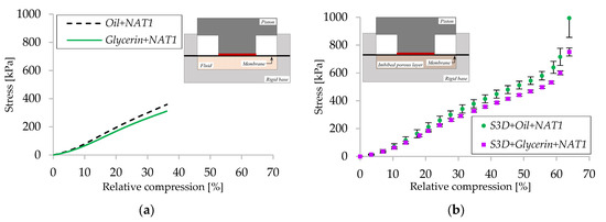
Figure 5.
Stress-relative compression variation: (a) comparison of EPHD damper using natural rubber membrane and fluid; (b) comparison of EPHD damper using natural rubber membrane and imbibed S3D.
The cumulative effect of the three mechanisms that contribute to device’s performance can be observed in Figure 5b. Here, the compression behavior of EPHD damper using imbibed S3D with glycerin and with oil is presented in average form (for 6 and 10 tests, respectively, performed on different specimens) with the standard deviation included. The average standard deviation calculated for stress is less than 20 kPa for glycerin and 35 kPa for oil, while the maximum deviation appears for relative compression values above 60% (120 kPa for glycerin, 139 kPa for oil). For the same level of compression, stress is slightly higher when using synthetic oil. In addition to the previously mentioned causes (Figure 5a), these differences can also be generated by the tolerances of the porous disk sizes, or by the friction of the membrane and of the piston with solid boundaries.
The results obtained on the damper when with dry contact between the piston and the membrane (Figure 5b) are compared with a similar test with lubricated contact (Figure 6). This confirms that the friction on the surface of the membrane is another factor that influences the overall response of the system.
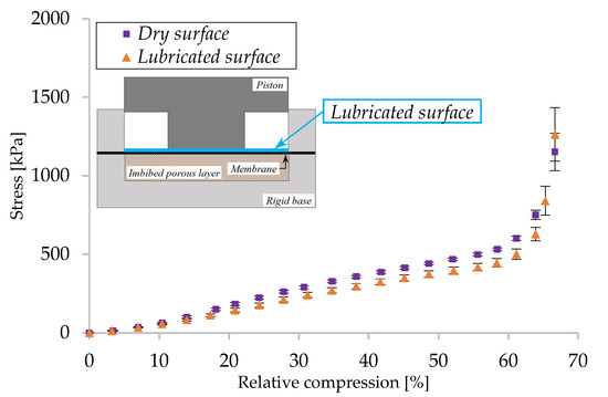
Figure 6.
Stress-relative compression variation for EPHD damper (S3D + glycerin + NAT1 configuration): dry vs. lubricated contact surface.
A complete loading–unloading cycle for three experimental configurations is presented in (Figure 7). The sudden increase in force values appears around a relative compression of 60%, this being considered the critical position, which corresponds to the inception of the densification stage with hcr ≈ 0.33 h0 (where h0 is the initial thickness of the porous material).
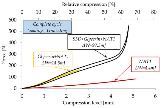
Figure 7.
Force–compression level variation for a complete cycle for 3 experimental configurations.
Based on this graph, one can calculate energy losses through hysteresis. When using natural rubber with glycerin imbibed S3D (S3D + glycerin + NAT1), the energy loss is 97.3 mJ. Comparing these results with the results obtained for glycerin + NAT1 without S3D, where the energy loss is 14.5 mJ, and with the results obtained for dry S3D (58.3 mJ—Figure 4a), it is confirmed one more time that the energy loss with the imbibed porous layer increases by 40%.
Visualization of the elastic membrane deformation generated by compression was performed with a transparent device (Figure 8), which highlights the deformed shape of the membrane. Even if the images recorded with the camera are slightly distorted (parallax error, refraction of the Plexiglas), one can see quite clearly the deformed shape of the membrane (torus).
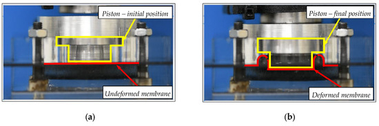
Figure 8.
Elasto-poro-hydrodynamic process visualization using a transparent device: (a) initial state; (b) deformed.
4. Simplified Analytical Model (SAM)
The objective of this model is to estimate the pressure of the fluid and the deformation of the rubber membrane function of the compression of the porous layer.
The literature offers many complex studies that address the deformation of elastic membranes with toroidal shape. Some studies that are worth mentioning are the ones carried out by Ponomariov et al. [22] who calculated the stresses and strains in cord and rubber fibers. Their model was based on the moment-free theory or membrane theory, which assumes that the toroidal shape is a thin-walled rotational shell. Jordan [23] and Sanders and Liepins [24] analyzed the stresses and strains occurring in toroidal membranes subjected to internal pressure. The problems that arise when inflating hyperelastic toroidal membranes were approached analytically by Kidoniefs and Spencer [25,26]. Recently, Roychowdhury et al. [27] studied the deformation of toroidal membranes under the action of uniform pressure, considering the influences of geometric and material parameters.
The following assumptions are considered:
- The membrane is perfectly elastic.
- An axially symmetric model is considered.
- The pressure inside the device is constant.
- The friction of the membrane and of the piston with solid boundaries is neglected.
- The thinning of the membrane due to elongation is neglected.
- The surface of the piston in the central area remains permanently parallel to the porous layer and in contact with the membrane.
- The thickness of the rubber membrane is small compared to its radius; as a result, the membrane cannot transmit bending moments and shear forces, being stressed only in tension.
- The stresses that appear at an arbitrary point in the membrane are constant in magnitude across the thickness; the radial elongation of the membrane is uniform.
- By unwrapping, the inflated membrane (half torus) becomes a half cylinder of infinite length that does not generate longitudinal stresses (ρ = ∞, σ = 0).
Based on the previous assumptions, one can use Laplace’s equation [22] for thin-walled bodies of revolution and Hooke’s law, to determine this pressure, as a function of the membrane elongation:
where E represents the secant modulus of elasticity of the rubber determined from traction tests, ε is the relative elongation, t is the thickness of the membrane, and ρ is the radius of curvature.
The elastic deformation (elongation) of the membrane can be split into two phases, schematically presented in Figure 9a and Figure 10a.
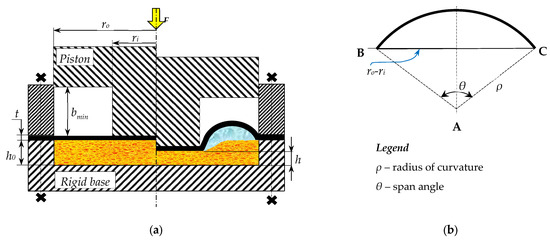
Figure 9.
(a) EPHD damper—Phase 1; (b) model geometry.
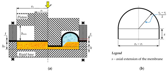
Figure 10.
(a) EPHD damper—Phase 2; (b) model geometry.
According to the theory of thin shells, during Phase 1, the membrane inflates continuously generating a half torus, defined in radial section by an arc of circle of radius ρ, and a span angle θ, Figure 9b. At the end of this phase, when the span angle θ = π, the cross-section becomes a semicircle of radius (ro − ri)/2.
Phase 2 is characterized by an axial displacement of the half torus, with the membrane adherent to the solid boundaries (piston and clamping collar), Figure 10b.
The geometry of the radial cross-section of the deformed membrane is derived using the volume conservation hypothesis, where the collected volume equals the expelled volume:
where A is the cross-sectional area of the inflated half torus, different for each phase, and ∆h = h0 − h is the deformation of the porous material:
Applying the volume conservation hypothesis to Equation (4), one can obtain the span angle, θ, as a function of compression of the porous material, Δh (for phase 1 of compression), as well as the axial extension, s, in phase 2.
The solutions of Equation (6) are obtained numerically, using a Solve block is Mathcad 15.0 software.
The relative elongation ε from Equation (3) can be determined as a function of radial elongation, Δr, and the compression of the porous material, Δh, respectively:
where Δr is the radial elongation of the membrane, different for each phase, obtained with the following equations:
Finally, considering all this, one can obtain the pressure formula for the two phases:
The reacting force on the piston given by the pressure generated inside can be calculated with [22]:
5. Finite Element Simulation (FES)
This section presents a finite element model of the EPHD damper that was developed using Abaqus 2021 software. This model was used to improve the understanding of the effects of variable parameters and of those that cannot be easily controlled experimentally on the device’s behavior.
For the present paper, we used a Standard and Explicit model. Since the geometry of the EPHD damper is relatively simple (circular shape), an axial symmetric model was chosen. It is composed of the main five parts (Figure 11) whose dimensions are consistent with those of the experimental device: a cup in which is positioned an imbibed disc of S3D, a rubber membrane, and a clamping collar (ring) that ensures the sealing during piston compression.
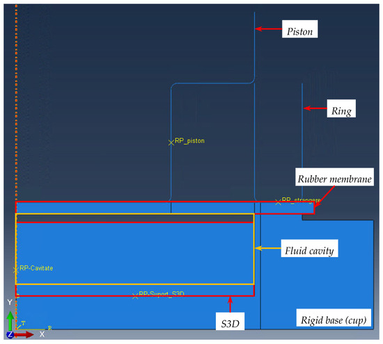
Figure 11.
EPHD-damper geometry Abaqus model.
The reference points (RPs), attributed to the components (Figure 11), can be used to apply constraints, boundary conditions, or define motions. Any feature applied to a reference point is also applied to the component to which it is associated.
One important aspect related to the finite element model is that from the three mechanisms, which contribute to the overall damping capacity/transmitted force, the developed model cannot replicate the fluid flow in the porous structure.
Compared to the physical device, the geometry of the physical model (Figure 1) underwent some modifications needed to replicate the experimental conditions. As can be observed, there is a clearance between S3D and the fluid cavity (in the proximity of the rubber membrane). There are two reasons behind this modification of geometry. First, the volume occupied by the fluid is less than the total volume of the cavity and can be calculated using the porosity of S3D, using Equation (13).
with Vfluid—the volume of the used fluid, Vcavity—the total volume of the cup, and ϕ0—initial porosity of the porous material.
The second reason is related to the mechanical behavior during quasi-static compression of S3D material. Analyzing Figure 12a, one can see the instability of material at the beginning of the compression (initial) stage (highlighted in Figure 12a), when the stress values are small, with respect to relative compression and sample dimensional deviations have great influence. A hyperfoam material from the Abaqus library was used to replicate the response of S3D. The behavior of the S3D material presented in Figure 12b was replicated in the numerical model only after eliminating stage I. This model, coupled with a third order strain energy function, provides a very good approximation of the results obtained from a series of standard compression tests (Figure 13). Exclusion of stage I can be seen in the geometry of the model, through the clearance Δc between the rubber membrane and porous material (Figure 14), basically reducing the initial thickness of the material.
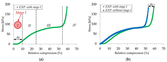
Figure 12.
Quasi-static compression of S3D: (a) all 4 stages of compression; (b) without initial stage.
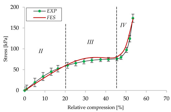
Figure 13.
Validation of the finite element model for S3D behavior.
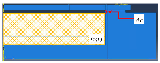
Figure 14.
Finite element model clearance, Δc.
For the rubber, the material model was also determined from a stress–strain curve, this time obtained by uniaxial tension tests for which the thermal effects were neglected. A hyperelastic model was implemented in Abaqus to describe the rubber. The Mooney–Rivlin model, with first-order strain energy potential, was chosen. The model was completed with information about rubber density and Poisson’s ratio.
The fluid cavity (as defined by Abaqus) was defined by specifying a surface that fully encloses the cavity, a cavity point, and by the density of the used fluid. The cavity surface is delimited by all the faces in the model that surround the cavity (bottom surface and internal wall of the cup and lower surface of the rubber membrane).
For the EPHD damper model, the rigid base and the rubber membrane are meshed using Quad-dominated elements and a free technique that offers more flexibility, being able to mesh more complex regions. For the meshing of S3D material, Quad elements are used, using a structured technique. Finally, the piston and the clamping collar are analytically rigid parts for which no mesh was needed.
The main boundary conditions applied to the model are as follows: the contact between the rubber membrane and the two steel parts (the ring part and the rigid base) was defined as a frictional contact, with a high friction coefficient of 0.7 (to simulate the clamping pressure), while for the interaction between the porous material and the cavity, a friction coefficient of 0.1 was used. Assuming complete imbibition of the porous material, the interaction between S3D and the rubber membrane was considered frictionless. For the contact between the piston and the membrane, a friction coefficient of 0.25 was defined. The values of these coefficients were established iteratively to obtain similar curves with experimental results.
6. Results and Discussions
During the experiments, it was observed that the S3D textile materials stabilize at lower stress values which are constant over time only after the first cycles of compression. This is the reason why the experimental results are presented in average form, including the standard deviation.
Furthermore, considering all the previously mentioned aspects, the experimental and numerical stress-relative compression curves for quasi-static compressions of the EPHD damper are represented graphically and compared in Figure 15. Two cases are analyzed: S3D imbibed with glycerin (Figure 15a) and with 5W30 synthetic oil, respectively (Figure 15b). The comparison was performed up to 66% relative compression, when S3D starts to behave progressively more as a rigid body.
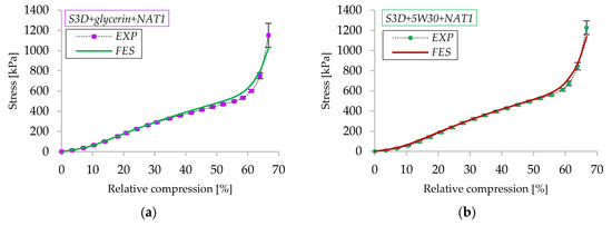
Figure 15.
Validation of finite element model: (a) with glycerin; (b) with oil.
Analyzing these two graphs, we can state the fact that the numerical results are in good agreement with the experimental results, demonstrating the validity of the FE model, hence providing a good approximation of the behavior of the EPHD damper in quasi-static conditions. Small differences between the two curves appear especially in the vicinity of the densification area of the porous material.
The experimental deformation history of the EPHD damper subjected to quasi-static compression is presented in Figure 16 with a compressive relative compression increment of ≈20%. These images were very helpful in the establishment of the analytical model assumptions.
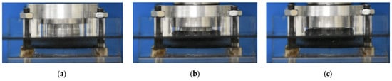
Figure 16.
Deformation history of EPHD damper under quasi-static compression (experimental): (a) ε = 0%; (b) ε ≈ 20%; (c) ε ≈ 40%.
Because there is no exact method of measuring the deformed shape of the membrane, we limit ourselves to the comparison with FES, which in turn was validated experimentally. Figure 17 shows schematically the deformation of the membrane, in radial cross-section, obtained theoretically for three representative compression levels. The contour of the membrane obtained with the analytical model is superposed on the mid-axis contour obtained by numerical simulation shown in the right side of the figure.
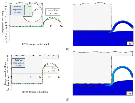
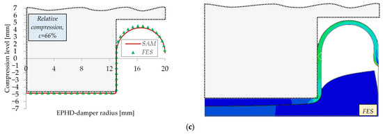
Figure 17.
Deformation history of EPHD damper under quasi-static compression–SAM vs. FES: (a) ε = 20%; (b) ε ≈ 40%; (c) ε ≈ 66%.
According to the simulation, in the beginning, the membrane is not in contact with the lateral surface of the piston in contrast with the analytical model assumption (Figure 17a—Detail). Because the expelled volume of fluid is the same, the height of the membrane inflation is lower for the analytical model. Increasing the level of compression, these differences attenuate. Overall, we can say that the analytical model provides a good approximation.
Since the elongation of the membrane during quasi-static compression of the EPHD damper cannot be easily determined experimentally, the two validated theoretical models are very useful for this purpose.
The graphs containing analytical model results are plotted with respect to a series of dimensionless parameters stated below:
- H = h/h0 is the relative deformation of the porous layer.
- R = ri/ro is the relative radius of the piston.
- T = t/ro is the shape factor of the membrane.
- K = h0/ro is the shape factor of the porous material.
The differences in terms of elongation obtained with SAM and FES are synthetically represented in Figure 18. For R = 0.5, the SAM and FES curves track each other closely, with low error values for Mean Absolute Error (MAE) = 0.78% and a Root Mean Square Error (RMSE) = 0.96%. This indicates the simplified model captures the deformation response reliably in this configuration. In this case, the position of the median axis of the membrane in the numerical model does not change substantially, and the thickness of the membrane remains constant. For R = 0.65, the deviation between SAM and FES increases significantly (MAE = 3.29%, RMSE = 3.86%). SAM underestimates elongation compared to FES, particularly at intermediate values of H. The differences are attributed mainly to the influence of the membrane thickness. Whilst in the analytical model the thickness is considered constant, in the numerical simulation, the membrane thins as it stretches. Secondary, the elongation of the membrane, which is placed between the piston and the porous layer, amplifies the elongation in the numerical simulation, unlike in the analytical model where it is assumed rigid.
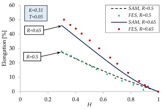
Figure 18.
Membrane elongation—analytical vs. FES.
The graph in Figure 19 shows the variation of the pressure generated inside the cavity as a function of the dimensionless thickness H of the porous layer. The pressure increases as the porous material is compressed, progressively deforming the membrane. The inflection points on the graph mark the transition between the two compression phases.
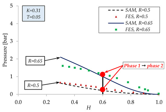
Figure 19.
Variation of pressure generated in the EPHD damper—analytical vs. FES.
For R = 0.5, the variation of the elastic pressure obtained with the analytical model is closer to the numerical one (MAE = 0.11 bar, RMSE = 0.12 bar). For R = 0.65, the transition from phase 1 to phase 2 causes the area of the deformed shape to increase faster; therefore, the slope of the pressure variation is smoother, and the differences between SAM and FES are slightly higher (MAE = 0.22 bar, RMSE = 0.25 bar).
The differences between the two curves can be caused by both the thickness of the membrane and the value of Young’s modulus of the rubber. In the analytical model, an average constant Young’s modulus is used, while in the numerical model, Young’s modulus is variable, as obtained from the experiments.
Considering the nonlinearities of the membrane material and the nonlinearities given by the geometry of its deformed shape, for a piston with a radius larger than R = 0.65, the differences between the analytical and numerical models are expected to increase.
Figure 20a shows the stress-relative compression response obtained experimentally and overlaps it with the results obtained using FES and SAM models. At the beginning of compression, in the linear region (0–35%), all three approaches follow close agreement, though SAM slightly underestimates the stress values, compared to EXP and FES. As relative compression increases, the response becomes nonlinear, ending with a steep increase in stress (densification of S3D material). At this moment, FES continues to capture experimental trends with high accuracy, while SAM diverges progressively from the experimental data, predicting lower stresses.
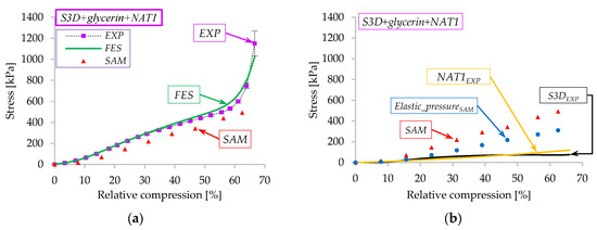
Figure 20.
(a) Comparison between EXP–FES–SAM results; (b) SAM curve contribution of each mechanism.
The quantitative error analysis confirms the qualitative trends observed in Figure 20a. The finite element simulation shows very good agreement with experiments with an MAE of 29 kPa and an RMSE of 48.8 kPa, capturing both the linear and nonlinear regimes with only minor deviations at higher compression levels. By contrast, the simplified analytical model (SAM) exhibits larger discrepancies MAE = 73.8 kPa and RMSE = 95.4 kPa, particularly in the nonlinear regime beyond ≈50% relative compression, where geometric and material nonlinearities such as membrane thinning and modulus variation become significant.
Overall, the comparison demonstrates that the FES approach provides a highly reliable predictive tool for this system (as previously stated), while the SAM is only suitable for approximating the linear elastic regime, where errors are moderate. This reinforces the need for advanced modeling techniques to accurately capture the nonlinear stiffening behavior at higher compression levels.
The values of stress using SAM are determined by summing the effects of the three mechanisms for the S3D+glycerin+NAT1 case (Figure 20b). The stress generated by the pressure inside the device (Elastic_pressure_SAM) was determined with SAM, while the deformation of the porous structure (S3DEXP) and of the rubber membrane (NAT1EXP) was taken from experimental data:
Analyzing Figure 20b, one can observe that the deformation of the porous structure and of the rubber membrane represents 16% and 22%, respectively, of the total stress on the damper, while the remaining 62% of the stress is generated by the elastic pressure inside the device.
Based on the information gathered from Figure 6, the FE model was used to study the influence of the coefficient of friction (COF) of the surface between the piston and the rubber membrane, and the results are presented in Figure 21.
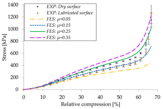
Figure 21.
Comparison between the FES and EXP results for different values of COF.
For the two experimental situations analyzed (dry and lubricated contact), the value of COF used in the FE model was obtained through an iterative process. For the dry contact surface, the numerical curve that offers the best approximation uses a COF of 0.25. For the lubricated surface, a value of 0.15 for COF was used. Another two situations, considering COF = 0.05 and 0.35, respectively, were analyzed. From this study, we can see that for the same level of compression, the pressure values obtained are higher when the friction between the two surfaces is more pronounced.
Figure 22 shows the results of numerical simulations showing stress-relative compression variation for three different thickness membranes: t = 0.5 mm, t = 1 mm, and t = 1.5 mm, considering COF = 0.25. The reference thickness is t = 1 mm, which was tested experimentally and for which the numerical model provided good approximation. Using a thinner membrane, t = 0.5 mm, the stress values are 45% lower than the reference case. In contrast, using a thicker membrane, t = 1.5 mm, the evolution is somehow predictable, with stress being 31% higher, when compared to the reference case.
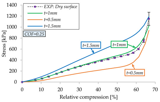
Figure 22.
Comparison between the FE simulations and experimental results for various thicknesses.
Superposing the aspects observed in Figure 21 and Figure 22, one can state the following: a lower COF between the piston and the membrane increases the contribution of the rubber membrane in hefty proportions; on the other hand, if a thinner membrane is used, the contribution of the porous material is substantial (densification stage is more noticeable). This information is reinforced by the fact that at the end of compression (≈66% relative compression), for t = 1 mm and t = 0.5 mm, the maximum stress values are similar.
The satisfactory correlation between the numerical simulation and the analytical model allows the use of the latter for a parametric analysis in dimensionless form.
The influence of the membrane thickness on the pressure is presented in Figure 23 for the reference case that was tested experimentally: R = 0.65 and K = 0.31 (shape factor of the porous material). One can see that at the critical level of compression (H = 0.33), the pressure generated by a thinner membrane (T = 0.025) is approximately 50% lower than a membrane with double thickness (T = 0.05). Being less rigid, a thinner membrane offers less resistance to the collection of fluid in the outer annular area of the piston. The greater the thickness, the more resistance it offers during fluid expulsion.
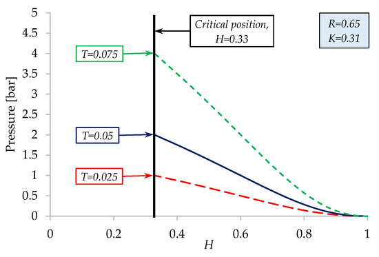
Figure 23.
Influence of membrane thickness (T) on the dimensionless pressure.
Radius of the piston is another parameter that has an important influence on the EPHD damper. The variation of the relative elongation of the rubber membrane as a function of the dimensionless thickness of the porous material, for different configurations of the piston (given by R), is shown in Figure 24. As expected, for a lower value of R, the relative elongation of the membrane decreases. With the volume of liquid displaced being smaller, the elongation of the membrane is also lower. The opposite situation is also valid. This graph confirms that the maximum relative elongation of the membrane (≈46%), obtained at critical position H = 0.33 (densification limit of the porous material), is included in the range 0–50%, where the membrane has a quasi-linear elongation.
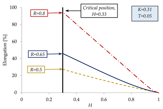
Figure 24.
Influence of piston radius (R) on the relative membrane elongation.
Considering all the simplifying assumptions considered, we can say that the simplified analytical model proposed provides a good approximation of the results of the numerical analysis.
7. Conclusions
This work introduces an original elasto-poro-hydrodynamic damper characterized by a progressive load-displacement characteristic, offering high load capacity. The model was tested in quasi-static conditions to select the best component materials and to evaluate its operating performances, with different configurations of materials fluids and rubber membranes. Within the validated quasi-static regime, both analytical and numerical models proposed proved useful in supporting design. The finite element approach captured stress–strain responses with good agreement to experiments, while the simplified analytical model enabled rapid estimation of membrane elongation, internal pressure, and deformed shapes, provided its assumptions are acknowledged. Also, the analytical model has proven to be a good solution for design, especially when choosing the dimensions of the piston and the thickness of the membrane and porous material.
From a design perspective, the results indicate that membrane thickness strongly influences force response. The observed sensitivity of damping behavior to friction highlights the importance of carefully controlling piston–membrane contact conditions in practical applications.
Several limitations must be emphasized. Validation was limited to quasi-static conditions, and the results cannot be directly generalized to dynamic or repetitive shock scenarios. The finite element model neglected porous fluid flow and relied on tuned friction coefficients, while the analytical model did not account for local thinning or variations in membrane modulus. Assembly tolerances such as fill volume and clamping also affect performance but were not fully captured. Finally, durability and cycling performance remain largely untested. These constraints should be considered when extending the present results to broader design use cases.
Author Contributions
Conceptualization, M.D.P., A.F. and T.C.; data curation, I.-R.N.; formal analysis, A.F. and T.C.; funding acquisition, P.T. and T.C.; investigation, I.-R.N. and P.T.; methodology, I.-R.N., M.D.P. and T.C.; project administration, P.T. and T.C.; resources, A.F. and T.C.; software, I.-R.N. and A.F.; supervision, M.D.P. and T.C.; validation, I.-R.N., P.T. and T.C.; writing—original draft, I.-R.N.; writing—review and editing, I.-R.N., P.T. and T.C. All authors have read and agreed to the published version of the manuscript.
Funding
This research was partially supported by a grant from the National Program for Research of the National Association of Technical Universities–GNAC2023ARUT (director: Petrică Turtoi) and partially by Executive Agency for Higher Education, Research, Development, and Innovation Funding (UEFISCDI), the Ministry of Education of Romania, through the National Project PN-IV-P7-7.1-PED-2024-1307 (director: Traian Cicone).
Institutional Review Board Statement
Not applicable.
Informed Consent Statement
Not applicable.
Data Availability Statement
The raw data supporting the conclusions of this article will be made available by the authors on request.
Conflicts of Interest
The authors declare no conflicts of interest.
Nomenclature
| A | cross-section area of the inflated half torus |
| E | Young’s modulus |
| F | load on the damper |
| h | thickness of the porous material |
| H | |
| K | |
| p | fluid pressure |
| r | radius |
| R | |
| s | axial extension of the membrane |
| t | membrane thickness |
| T | |
| Δh | compression of the porous material |
| Δr | radial elongation |
| ε | |
| θ | span angle |
| ρ | radius of curvature |
| σ | circumferential stress |
| ϕ | porosity of the porous material |
| Subscripts | |
| 0 | initial |
| 1, 2 | phase of the inflation |
| i | inner |
| o | outer |
| Abbreviations | |
| COF | coefficient of friction |
| EPHD | elasto-poro-hydrodynamic |
| EXP | experimental |
| FES | finite element simulation |
| MAE | mean absolute error |
| NAT1 | natural rubber |
| RMSE | root mean square error |
| RP | reference point |
| S3D | soft fibrous 3D textile |
| SAM | simplified analytical model |
| XPHD | ex-poro-hydrodynamic |
References
- MacNeal, R.H.; Loisch, J. On the Use of Filament Wound Toroids as Pneumatic Shock Absorbers; Report Number: NASA-CR-574; Astro Research Corporation NASA: Santa Barbara, CA, USA, 1966; pp. 1–43. [Google Scholar]
- Han, Q.; Ming, J.; Lu, Y.; Liu, M. Mechanical behaviors of air spring-FPS three-dimensional isolation bearing and isolation performance analysis. Soil Dyn. Earthq. Eng. 2021, 149, 106872. [Google Scholar] [CrossRef]
- Yin, L.; Xu, W.; Hu, Z.; He, M.; Li, C. Research on Damping and Vibration Absorption Performance of Air Spring Dynamic Vibration Absorber. J. Vib. Eng. Technol. 2024, 12, 3771–3782. [Google Scholar] [CrossRef]
- Cheng, Y.; Gao, H.; Ma, J.; Shuai, C. Stiffness analysis and structural optimization design of an air spring for ships. Sci. Rep. 2024, 14, 14650. [Google Scholar] [CrossRef] [PubMed]
- Moss, E.A.; Krassnokutski, A.; Skews, B.W.; Paton, R.T. Highly Transient squeeze-film flows. J. Fluid Mech. 2011, 671, 384–398. [Google Scholar] [CrossRef]
- Krassnokutski, A.; Moss, E.A.; Skews, B.W. An experimental study of highly transient squeeze-film flows. Phys. Fluids 2013, 25, 063102. [Google Scholar] [CrossRef]
- Pascovici, M.D.; Cicone, T. Squeeze-film of unconformal, compliant and layered contacts. Tribol. Int. 2003, 36, 791–799. [Google Scholar] [CrossRef]
- Pascovici, M.D.; Cicone, T.; Marian, V.G. Squeeze process under impact in highly compressible porous layers, imbibed with liquids. Tribol. Int. 2009, 42, 1433–1438. [Google Scholar] [CrossRef]
- Melciu, I.C.; Cicone, T.; Pascovici, M.D. Saturated porous layers squeezed between parallel disks in enclosed cells. In IOP Conference Series: Materials Science and Engineering; IOP Publishing: Bristol, UK, 2017; Volume 174. [Google Scholar] [CrossRef]
- Turtoi, P.; Pascovici, M.D. Finite volume squeeze flow in highly compressible porous annular discs. UPB Sci. Bull. Ser. D 2016, 78, 43–56. [Google Scholar]
- Turtoi, P.; Pascovici, M.D.; Cicone, T. Squeeze flow of Bingham fluids through reticulated, compressed foams. Lubricants 2019, 7, 86. [Google Scholar] [CrossRef]
- Cicone, T.; Pascovici, M.D.; Melciu, I.C.; Turtoi, P. Optimal porosity for impact squeeze of soft layers imbibed with liquids. Tribol. Int. 2019, 138, 140–149. [Google Scholar] [CrossRef]
- Turtoi, P.; Pascovici, M.D.; Cicone, T.; Rotariu, A.N.; Puică, C.C.; Istrate, M. Experimental proof of squeeze damping capacity of imbibed soft porous layers subjected to impact. In IOP Conference Series: Materials Science and Engineering; IOP Publishing: Bristol, UK, 2018. [Google Scholar] [CrossRef]
- Melciu, I.C. Repetitive Squeeze Processes in Complex Media. Ph.D. Thesis, University POLITEHNICA of Bucharest, Bucharest, Romania, 2019. (In Romanian). [Google Scholar]
- Nabhani, M.; El Khlifi, M.; Bou-Saïd, B. A generalized model for porous flow in squeezing film situations. Lubr. Sci. 2010, 22, 37–53. [Google Scholar] [CrossRef]
- Yousfi, M.; Bou-Saïd, B.; Tichy, J. An analytical study of the squeezing flow of synovial fluid. Mech. Ind. 2013, 14, 59–69. [Google Scholar] [CrossRef]
- Miao, X.H.; Ge, M.Q. The compression behavior of warp knitted spacer fabric. Fibres Text. East. Eur. 2008, 16, 90–92. [Google Scholar]
- Liu, Y.P.; Hu, H.; Zhao, L.; Long, H.R. Compression behavior of warp-knitted spacer fabrics for cushioning applications. Text. Res. J. 2012, 82, 11–20. [Google Scholar] [CrossRef]
- Liu, Y.P.; Hu, H. An experimental study of compression behavior of warp-knitted spacer fabric. J. Eng. Fiber Fabr. 2014, 9, 61–69. [Google Scholar] [CrossRef]
- Liu, Y.P.; Hu, H. Finite element analysis of compression behaviour of 3D spacer fabric structure. Int. J. Mech. Sci. 2015, 94–95, 244–259. [Google Scholar] [CrossRef]
- Lupu, G.C.; Fatu, A.; Henry, Y.; Turtoi, P.; Cicone, T. Mechanical and structural characterisation of a 3D warp-knitted spacer fabric subjected to compression. In IOP Conference Series: Materials Science and Engineering; IOP Publishing: Bristol, UK, 2022; Volume 1262. [Google Scholar] [CrossRef]
- Ponomariov, S.D.; Biderman, V.L.; Liharev, K.K.; Makușin, V.M.; Malinin, N.N.; Feodosiev, V.I. Strength Calculation in Mechanical Engineering; Translated from Russian in Romanian; Technical Publishing House of Bucharest: Bucharest, Romania, 1963; Volume 2, pp. 573–580. [Google Scholar]
- Jordan, P.F. Stresses and Deformations of the Thin-Walled Pressurisez Torus. J. Aerosp. Sci. 1962, 29, 213–225. [Google Scholar] [CrossRef]
- Sanders, J.L., Jr.; Liepins, A.A. Toroidal Membrane under Internal Pressure. Am. Inst. Aeronaut. Astronaut. 1963, 1, 2105–2110. [Google Scholar] [CrossRef]
- Kydoniefs, A.D. The finite inflation of an elastic toroidal membrane. Int. J. Eng. Sci. 1967, 5, 477–494. [Google Scholar]
- Kydoniefs, A.D.; Spencer, A.J.M. The finite inflation of an elastic torus. Int. J. Eng. Sci. 1965, 3, 173–195. [Google Scholar] [CrossRef]
- Roychowdhury, S.; DasGupta, A. Inflating a flat toroidal membrane. Int. J. Solids Struct. 2015, 67–68, 182–191. [Google Scholar] [CrossRef]
Disclaimer/Publisher’s Note: The statements, opinions and data contained in all publications are solely those of the individual author(s) and contributor(s) and not of MDPI and/or the editor(s). MDPI and/or the editor(s) disclaim responsibility for any injury to people or property resulting from any ideas, methods, instructions or products referred to in the content. |
© 2025 by the authors. Licensee MDPI, Basel, Switzerland. This article is an open access article distributed under the terms and conditions of the Creative Commons Attribution (CC BY) license (https://creativecommons.org/licenses/by/4.0/).