Article

A Rapid Modeling Method for Sound Radiation of China’s Locomotive Traction Drive Systems in Railways

1
State Key Laboratory of Heavy-Duty and Express High-Power Electric Locomotive, CRRC Zhuzhou Locomotive Co., Ltd., Zhuzhou 412001, China
2
School of Mechanical Engineering, Southeast University, Nanjing 211189, China
*
Author to whom correspondence should be addressed.
Appl. Sci. 2025, 15(19), 10597; https://doi.org/10.3390/app151910597
Submission received: 16 August 2025 / Revised: 23 September 2025 / Accepted: 29 September 2025 / Published: 30 September 2025
(This article belongs to the Section Acoustics and Vibrations)

Abstract

As a core component of high-speed trains, the traction drive system is also one of the main sources of both pass-by noise and interior noise. Current research primarily focuses on the modeling and design of its dynamic characteristics, while studies on its sound radiation remain relatively scarce. Existing investigations mainly rely on experimental and finite element methods. This paper proposes a rapid modeling method for the sound radiation of traction drive systems and analyzes the acoustic characteristics under different train speeds and gear helix angles. Taking an electric freight locomotive operating on China’s railways as the subject, the primary noise sources were identified through real-vehicle testing, thereby simplifying the non-dominant noise sources. By integrating a gear system dynamic model with theoretical models of gear meshing noise and motor noise, the proposed approach avoids the complexity and high computational cost associated with traditional finite element methods. The results show that at lower train speeds, the main noise source is the motor, while at higher speeds, it is the gearbox. As the train speed and helix angle increase, the radiated sound pressure of the traction drive system first increases and then decreases, though the sound field distribution and directivity remain largely unchanged.

1. Introduction

As a core component of high-speed trains, the traction drive system largely determines power quality, energy consumption, and control characteristics, thereby critically influencing the economic efficiency, comfort, and reliability of train operations [1,2]. Presently, most electric multiple units are powered by high-voltage power grids, whose traction drive systems can be classified into electrical and mechanical subsystems from an energy perspective [3,4,5,6,7]. This paper focuses on the mechanical component of the traction drive system, which primarily comprises the traction motor, coupling, and gearbox. For the sake of clarity, references to the traction drive system in the subsequent sections specifically denote its mechanical component.
Due to the inherent complexity of traction drive systems and their rich internal nonlinear excitations, the components in high-speed operations are often subjected to high-frequency vibrations. Consequently, extensive research has been conducted on dynamic modeling [8,9], control [10,11] and analysis [12,13,14] of these systems. Zhao et al. [15] developed a Lagrange dynamic model for the traction drive system that accounts for the nonlinear meshing forces of the gears, and they validated the model’s accuracy using test data. Based on established vehicle-track coupled dynamics and gear dynamic theories, Zhang et al. [16] constructed a coupled dynamic model for locomotives and tracks that incorporates the dynamic effects of the gear transmission system. They conducted simulations and analyses of the vibration accelerations for various components within the vehicle system as it accelerated from 10 km/h to 60 km/h during the traction and startup phases. However, in the above studies, the coupling motor is oversimplified, precluding an accurate assessment of the complex effects of the motor’s simple harmonic torque on the dynamic characteristics of the traction drive system. Wu et al. [17] demonstrated through field testing of traction motors that voltage pulsations in the traction drive system generate distinct frequency components during both traction and braking operations, particularly at high speeds. Ye et al. [4] developed a simulation model that accounts for the electromechanical coupling between the vehicle and control subsystems, enabling a comprehensive analysis of a locomotive’s dynamic response to both electrical and mechanical excitations. Zhang et al. [18] developed an electromechanical coupling model for high-speed trains under various operating conditions by incorporating gear pair interactions, drive-train connecting devices, traction motor equivalent circuits, and torque control strategies. Their results indicate that the meshing frequency and high-order rotation frequency are the primary characteristic frequencies. Similarly, Wang et al. [19] developed an electromechanical coupling model for the traction drive system and analyzed the influence of the 100 Hz beat frequency component on its performance.
The primary aim of previous research on dynamics has been to ensure the operational safety and ride comfort of high-speed trains under complex nonlinear excitations. However, the intricate excitations imposed on the enclosing structure inevitably generate radiated noise. Indeed, traction drive train noise constitutes a major component of both pass-by and interior noise from electric locomotives [20]. As ride comfort requirements continue to increase, more stringent noise standards for traction drive systems have become necessary. Soeta et al. [21] investigated the influences of wheel and track noise, as well as motor and gearbox contributions, on in-vehicle acoustics. They quantified the variability in the components of rolling noise, impact noise, and curve whine across different frequency bands. Sapena et al. [22] developed an internal noise prediction model for high-speed trains using the finite element-statistical energy analysis (FE-SEA) method. This model accounts for both structural vibration transmission and airborne propagation, incorporating contributions from components such as the bogie, traction motors, and gearboxes. Additionally, references [23,24,25] reduced electromagnetic noise by optimizing motor parameters.
In summary, there are considerably fewer studies on the radiated noise of locomotive traction drive systems compared to investigations of their dynamics. Moreover, most existing research on radiated noise in traction drive systems employs either experimental testing or FE-SEA numerical modeling methods. Although experimental methods most closely approximate engineering reality, they are expensive and can impede the comprehensive understanding of parameter influences through extensive repetitions. Moreover, the FE-SEA simulation approach demands substantial computational resources, particularly for complex structures, such as those involving gear contact, which is characterized by highly nonlinear behavior. To overcome these challenges, this paper presents a rapid modeling approach for radiated noise in traction drive systems by integrating theoretical modeling with finite element simulation. Initially, a nonlinear dynamic model of the gear transmission system is developed, and the dynamic force excitation on the gearbox housing is computed using this model. Subsequently, theoretical formulas are employed to determine the equivalent point source parameters for meshing and motor noises. Finally, a simplified finite element model of the entire traction drive system is constructed based on the derived dynamic force excitations and point source parameters, thereby significantly enhancing simulation speed and reducing computational cost.

2. Configuration of Locomotive Traction Drive Systems

Figure 1 illustrates a schematic diagram of the traction drive system. The primary components include a motor, gearbox, wheel axle, drum-tooth coupling, and rubber sleeve. In this configuration, the motor and gearbox are mounted on the wheel axle and secured within the surrounding frame by the rubber sleeve, while the drum-tooth coupling connects the motor and gearbox to facilitate power transmission.

3. Vibro-Acoustic Test and Analysis

To identify the primary sound sources and provide a foundation for subsequent simplified modeling, vibration and noise signals in the actual locomotive traction system were examined and analyzed.

3.1. Sensor Arrangement and Main Test Conditions

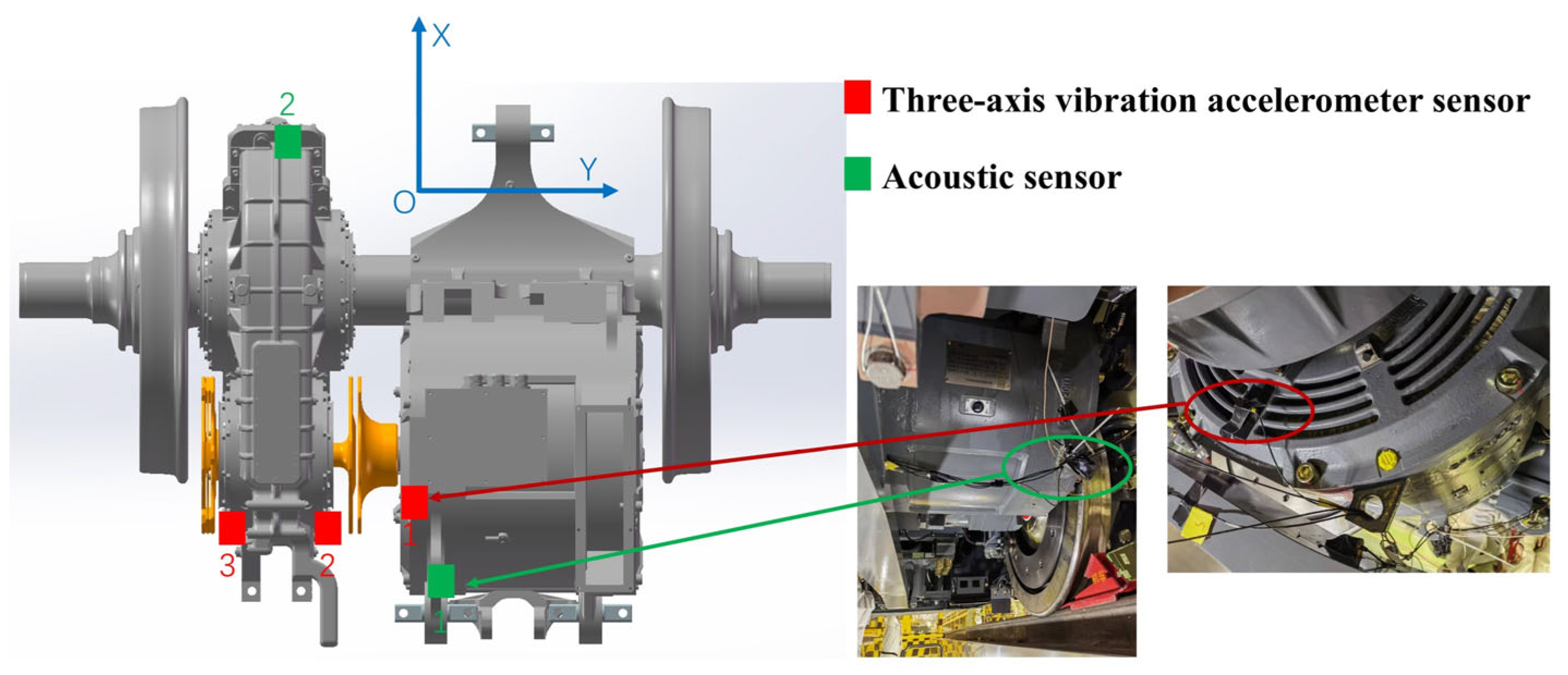
The acoustic and vibration sensors were arranged along the power transmission direction, with the precise placements of the three-directional vibration acceleration sensors (PCB 356B08, PCB Piezotronics, Depew, NY, USA) and acoustic sensors (BK 1706, Brüel & Kjær, Nærum, Denmark.) in the experiment illustrated in Figure 2.
An identical locomotive was utilized as the power source to haul the test locomotive equipped with the traction transmission system. The vehicle testing was conducted on a track within a laboratory environment at varying speeds, during which the sensors recorded acoustic and vibration signals throughout the locomotive’s entire operation. A total of five operating conditions were evaluated, and the corresponding parameters for each condition are provided in Table 1 below.
It is worth noting that the actual meshing frequency is slightly higher than the calculated meshing frequency due to the stick-slip phenomenon.

3.2. Analysis of Testing Results

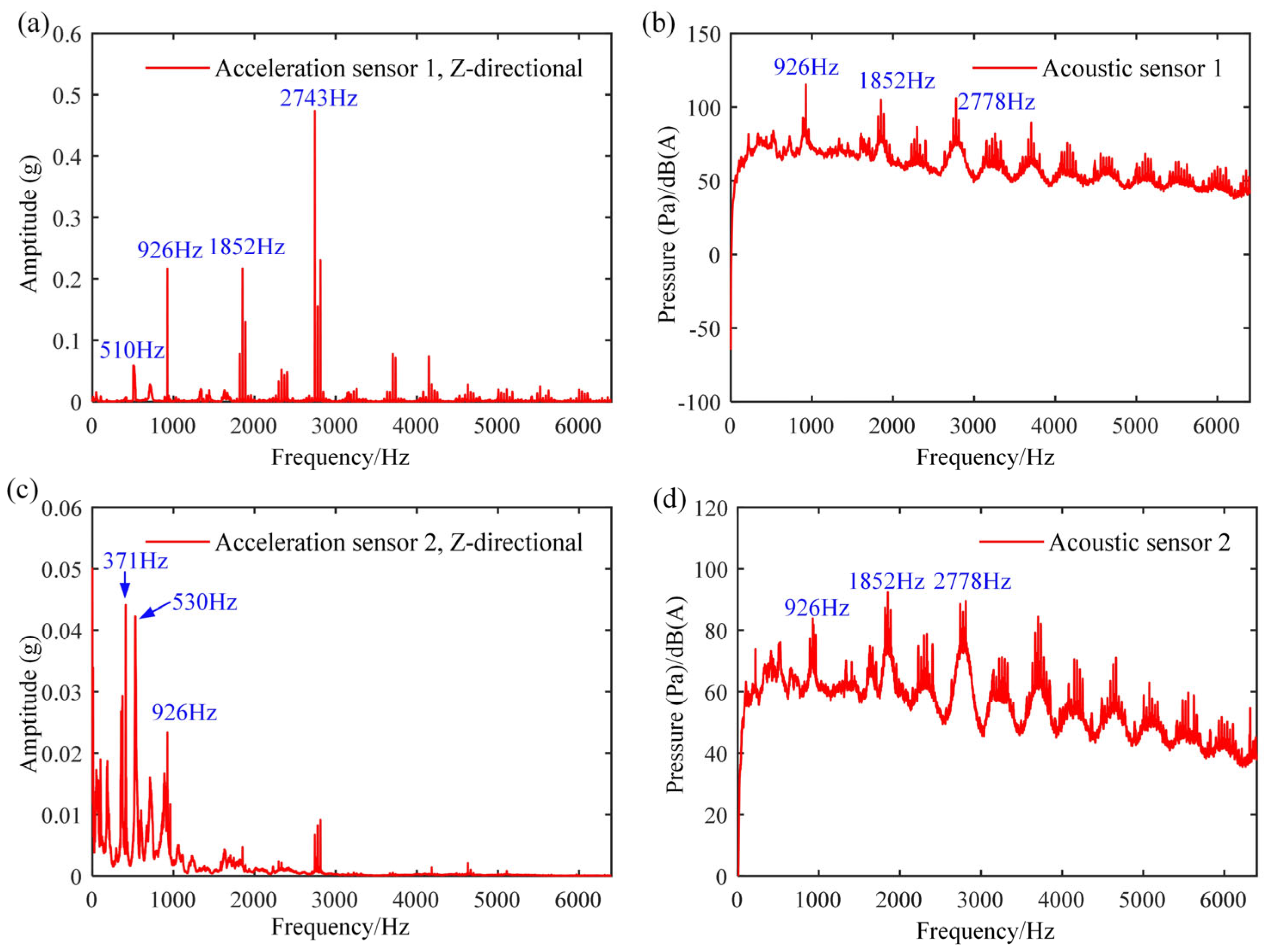
The vibration and acoustic signals were extracted for five distinct working conditions. Taking working condition 1 as an example, its motor and gearbox vibration and acoustic signals are presented in Figure 3. Due to space constraints, we only present the vibration signal in the z-direction. Figure 3a illustrates the motor vibration signal; Figure 3b, the corresponding acoustic signal; Figure 3c, the gearbox vibration signal; and Figure 3d, the respective acoustic signal.
From Figure 3, the characteristic frequencies of the motor noise signal (926 Hz, 1852 Hz, and 2778 Hz) in Figure 3b correspond to those in the frequency spectrum of the motor vibration signal shown in Figure 3a. This correspondence indicates that the noise is predominantly generated by vibrations of the motor structure. Additionally, the gearbox vibration signal in Figure 3c exhibits resonance peaks corresponding to the meshing frequency of 175 Hz and its higher-order harmonics. However, the frequency characteristics of the gearbox noise in Figure 3d remain consistent with those of the motor noise and vibration. These findings imply that under low-speed operating conditions, the sound radiation generated by gearbox vibrations is significantly lower than that produced by the motor.
The characteristic frequencies of the noise and vibration signals for the remaining operating conditions are listed in Table 2. It can be observed that under Conditions 2 and 3, the noise characteristics are almost exclusively dominated by motor vibration frequencies, while gearbox vibration frequencies are scarcely discernible in the noise spectrum. For instance, under Condition 2, the noise characteristic frequencies include 933 Hz, 1857 Hz, and 2780 Hz, all of which correspond to motor vibration frequencies, while only 933 Hz can also be found among the gearbox vibration frequencies. A similar pattern can be observed under Condition 3. Therefore, it can be inferred that the noise is primarily influenced by motor vibrations, consistent with the phenomenon observed under Condition 1. However, when the locomotive speed is further increased as in Case 4, three of the four characteristic frequencies in the traction drive system’s noise emanate from gearbox vibrations, with only one frequency attributable to the motor. This finding indicates that as the locomotive speed increases, the gearbox’s contribution to the traction drive train noise gradually becomes more predominant. Notably, under condition 5, the motor eigenfrequency is absent from the noise spectrum, clearly demonstrating that, at this higher speed, the gearbox’s contribution to system noise far exceeds that of the motor.
Based on the above analysis, when the locomotive operates at low speeds, gearbox vibration levels are low, and the traction drive system’s noise is predominantly generated by motor vibrations. However, as the speed increases, gearbox vibrations gradually become the primary source of radiated noise. Considering that the experimental maximum speed is 60 km/h, whereas the rated operational speed is 114 km/h, subsequent modeling of the traction drive system’s sound radiation should incorporate a refined treatment of gearbox noise, while a more simplified approach may suffice for motor noise.

4. Rapid Modeling of Acoustic Radiation

Direct finite element calculations for the traction drive system result in a high computational cost, long processing times, and poor convergence, all of which hinder subsequent optimization calculation. To overcome these challenges, the proposed modeling approach replaces the finite element computation of the gear meshing process with nonlinear dynamic equations. Meanwhile, the motor is also simulated using theoretical modeling, with finite element analysis reserved only for the gearbox within the traction drive system. By applying the forces and acoustic excitation calculated from the theoretical models to the finite element model of the gearbox, an overall acoustic model of the traction drive system is established. The specific modeling process is shown in Figure 4.

4.1. Parametric Modeling and Verification of Gear System

To simplify the helical gear transmission system, the following assumptions are adopted without loss of generality: the meshing force is uniformly distributed along the tooth width, always aligned with the theoretical meshing line and directed along the extension line; deformation of the shorter gear shaft is neglected; and bearing clearance is ignored. Furthermore, only the transverse and longitudinal degrees of freedom, along with the rotational degree of freedom about the z-axis, are considered [26,27]. Consequently, a 2-node, 8-degree-of-freedom gear dynamic model is established, as illustrated in Figure 5.
In Figure 5, O p and O g denote the rotational centers of the driving and driven wheels, respectively, while r p and r g represent the base circle radii of these wheels. The helix angle is represented by β b , the installation phase angle by ψ , and the end face pressure angle by α t . The angle φ , defined as the angle between the translational action line and the y -axis, relates to the end face pressure and installation phase angles by the equation φ = α t ψ . Additionally, T p and T g denote the input and output torques, respectively, and k ( i = 1 , 2 ; j = x , y , z ) represent the bearing support stiffnesses along each coordinate axis.
The gear dynamic equation can be obtained from Newton’s second law as
m 1 x ¨ 1 + c 1 x x ˙ 1 + k 1 x x 1 + F p c o s β b s i n Ψ = 0 m 1 y ¨ 1 + c 1 y y ˙ 1 + k 1 y y 1 + F p c o s β b c o s Ψ = 0 m 1 z ¨ 1 + c 1 z z ˙ 1 + k 1 z z 1 + F p s i n β b = 0 J z 1 θ ¨ z 1 + F p r b 1 c o s β b = T p m 2 x ¨ 2 + c 2 x x ˙ 2 + k 2 x x 2 F p c o s β b s i n Ψ = 0 m 2 y ¨ 2 + c 2 y y ˙ 2 + k 2 y y 2 F p c o s β b c o s Ψ = 0 m 2 z ¨ 2 + c 2 z z ˙ 2 + k 2 z z 2 F p s i n β b = 0 J z 2 θ ¨ z 2 + F p r b 2 c o s β b = T g
Herein, F p = c m δ ˙ d + k m x t τ m is the meshing force, where τ m is the meshing stiffness compression, and δ d = V x represents the meshing line displacement. V denotes the projection vector of the gear node displacement along the normal meshing line direction, and x denotes the generalized coordinate definition of the master and slave nodes of the gear pair, as expressed by the following equations:
V = c o s β b s i n Ψ , c o s β b c o s Ψ , s i n β b , r p c o s β b , c o s β b s i n Ψ , c o s β b c o s Ψ , s i n β b , r g c o s β b , x = x 1 , y 1 , z 1 , θ 1 z , x 2 , y 2 , z 2 , θ 2 z T
The meshing stiffness directly determines the nonlinear characteristics of the system. In this paper, the contact line method is used to calculate the full tooth width meshing stiffness of helical gears. Within a single meshing cycle, the contact line length and full tooth width meshing stiffness can be in a direct proportional relationship. Therefore, the time-varying meshing stiffness can be calculated based on the time-varying meshing line length and the average meshing stiffness. Thus, the relationship between τ m and δ d can be expressed as:
τ m = δ d t e m t b , δ d t e m t > b 0 , δ d t e m t b δ d t e m t + b , δ d t e m t < b
where e m represents transmission error, and b represents tooth side clearance.
The change in the length of the contact line on a single pair of teeth is shown in Figure 6. When b t a n β b > L C D , the maximum length of the mesh line is L C D c s c β b . The change in the mesh line during the gear meshing and disengagement process can be regarded as the product of the maximum length of the mesh line and the periodic segmented linear function γ ( t ) . When b t a n β b < L C D , the maximum length of the mesh line is b s e c β b . The change in the mesh line during the gear meshing and disengagement process can similarly be regarded as the product of the maximum length of the mesh line and the periodic piecewise linear function γ ( t ) . In summary, the instantaneous contact line length of a single pair of teeth is expressed as:
L t = L CD c s c β b γ t               ε β > ε α b sec β b γ t                   ε β ε α
where γ ( t ) is a periodic piecewise linear function, which can be expressed as:
γ t = t / min ε a , ε b         0 t = m o d ( t , n t c ) / t c < min ε a , ε b   1           min ε a , ε b t < max ε a , ε b 1 ( t max ε a , ε b ) / min ε a , ε b       max ε a , ε b t < ε 0                 ε t n
Due to the periodicity of the system, the total contact line length of the meshing teeth for any favorable direction is:
L z t = i = 1 n L i 1 t c + m o d t , t c
Herein, i = 1 , , n = c e i l ( ε ) , where the ceil function is the ceiling function, ε is the total overlap angle, t c = P t / ( Ω p r b p ) , Ω p and r b p are the angular velocity and base circle radius of the driving gear, respectively, and P t is the base pitch length of the helical gear.
Substituting Equations (4)–(6) into (3), the compression of the meshing stiffness can be calculated based on changes in the meshing line length. Subsequently, the meshing force can be calculated, thereby completing the establishment of the entire gear concentrated parameter model Equation (1).
To verify the correctness and accuracy of the theoretical model, a multi-body dynamic simulation of the gear system was performed using ADAMS [28] software (version 2020). The gear parameters are detailed in Table 3. After completing the gear mesh division, appropriate loads and boundary conditions were defined for the driving and driven gears, as illustrated in Figure 7.
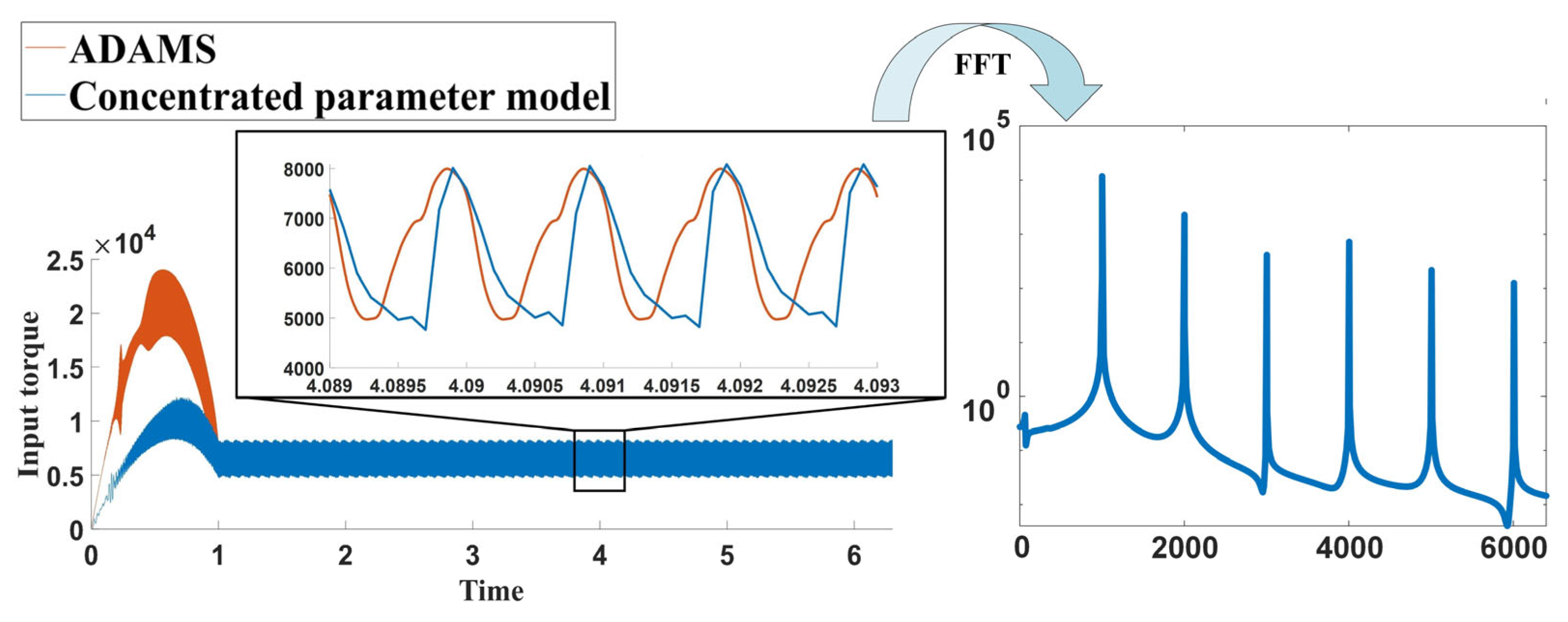
The time-domain and frequency-domain comparisons of the input torque between the ADAMS simulation and lumped parameter model established by MATLAB R2023b [29] are shown in Figure 8. It can be seen that the input torque calculation results of the lumped parameter model are basically consistent with the simulation results after the gear operation stabilizes. The spectra of the two are basically overlapping, with a meshing frequency of 1001.3 Hz. Therefore, the concentrated parameter model provides accurate results and good simulation performance. Regarding the discrepancies in the transient stage results, it is speculated that the support stiffness causes significant fluctuations in the input torque during startup in the lumped parameter model.

4.2. Dynamic Force Excitation Calculation for Gearbox Housing

To provide the multi-frequency excitation required for subsequent sound field calculations at the gearbox bearings, the three-dimensional displacements and velocities of the driving and driven gear bearings under various operating conditions were first computed using the established gear theoretical model. By incorporating the bearing support stiffness and damping, the time-domain dynamic loads at each bearing location within the gearbox were determined. A fast Fourier transform was then applied to convert these time-domain dynamic loads into the frequency domain, thereby obtaining the full-frequency excitation for a single operating condition.
The locomotive operating conditions considered in this theoretical model are presented in Table 4, where Conditions 1–5 align with those used in the experimental tests, and Condition 6 corresponds to the operating speed at the motor’s rated rotation speed.
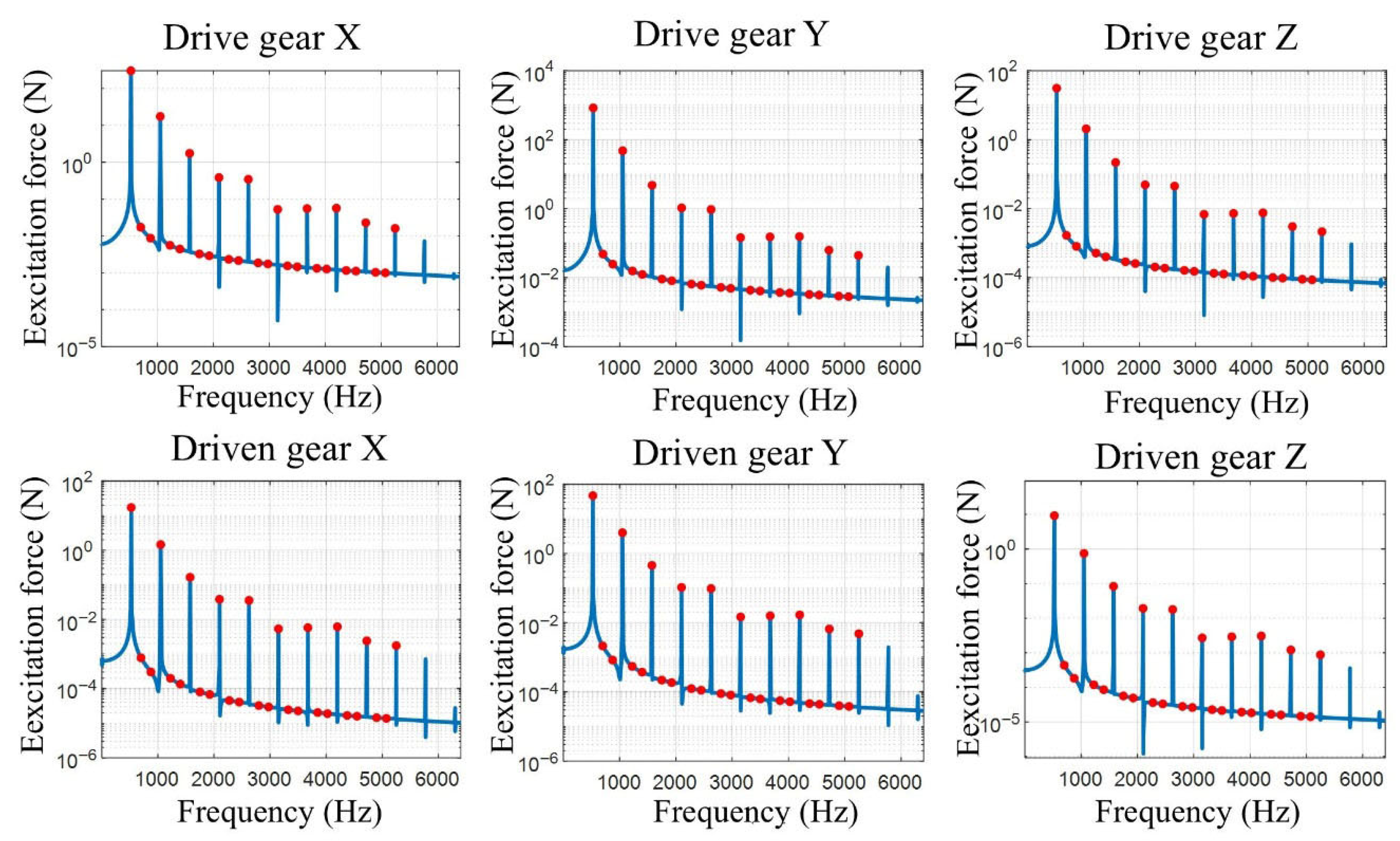
Taking operating condition 5 as an example, the three-dimensional load spectrum of the main and driven gears on the gearbox bearings is shown in Figure 9. As shown by the red solid points in Figure 9, to obtain full-frequency excitation under a single operating condition, it is necessary to select the main characteristic frequencies for that condition. First, the meshing frequency and its harmonics are selected as sampling points. Subsequently, several sampling points are selected between the harmonics to cover the entire frequency range. Finally, the excitation forces at each frequency are sequentially applied to the main and driven bearing seats of the gearbox, thereby calculating the sound pressure level at each excitation frequency under a single operating condition. Further, using Equation (7), the total sound pressure level under a single operating condition can be determined.
O A S P L = 10   l o g 10 ( ( 10 S P L 10 × f ) )
where OASPL is the total sound pressure level, SPL is the sound pressure level at each frequency, and f is the bandwidth between adjacent frequencies.
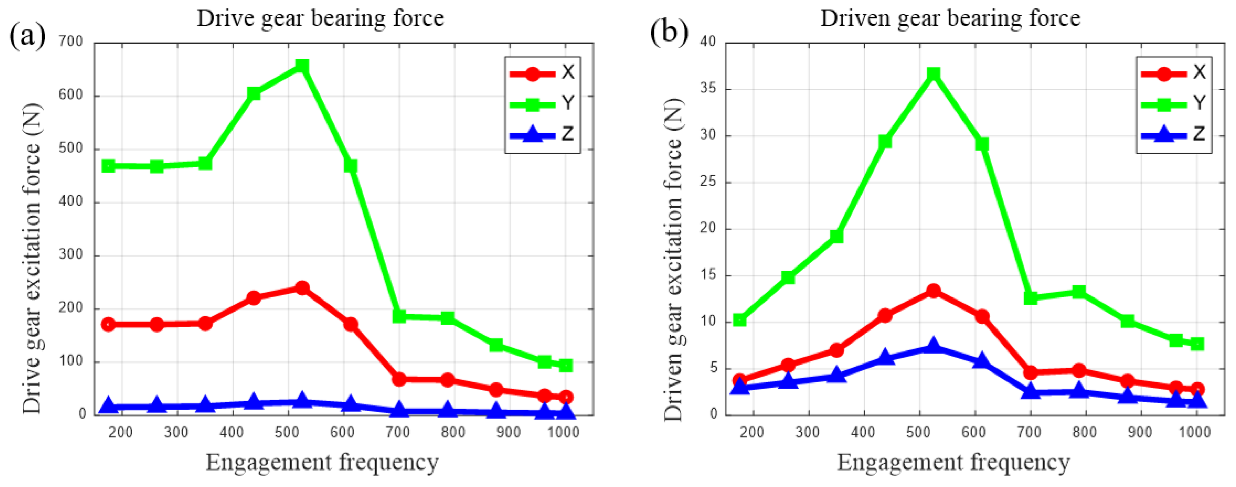
Figure 10 shows the three-directional force excitation of the drive and driven gear bearing under different operating conditions. It is evident that the force in the y-direction, i.e., the tangential direction of the gear, is the largest, which is consistent with the kinematic characteristics of the gear. Furthermore, the variation patterns of the excitation forces in all three directions are identical: as the excitation frequency increases, the amplitude of the excitation force first increases and then decreases.

4.3. Meshing Noise Excitation Calculation

The nonlinear impact generated by gear meshing causes the gear system to vibrate and generate noise [30,31]. This paper adopts T. Masuda formula, which not only considers the effects of factors such as helix angle and transmission ratio, but also takes into account the influence of gear vibration itself. Based on the experimental findings that the product of transmitted power and gear system vibration peak is highly correlated with noise, a power term has been added to the calculation formula, making the improved formula more realistic [32]. The formula is as follows:
L = 20 ( 1 tan ( β / 2 ) ) u 8 ε α 4 5.56 + v 5.56 + 20 l o g W + 20 l o g X + 20
where L is the sound pressure level at a distance of 1 m from the sound source, W is the transmitted power of the gear, u is the gear transmission ratio, β is the gear helix angle, ε a is the gear overlap ratio, v is the gear linear velocity, and X is the gear vibration peak value.
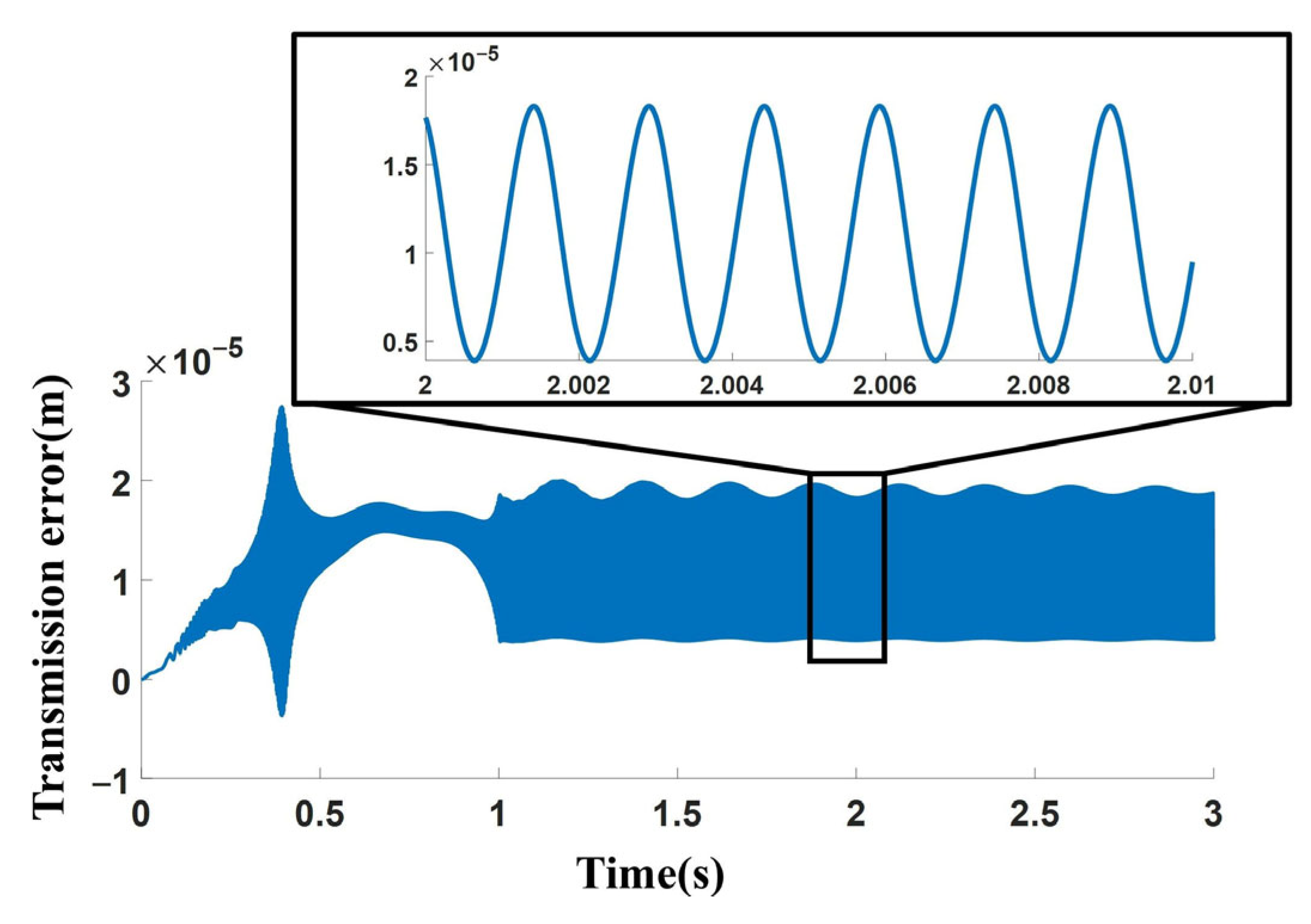
Since the T. Masuda [33] formula requires the calculation of specific vibration responses, the gear concentrated parameterization model established in the preceding section is used for the calculation. There are six operating conditions for train operation. Taking operating condition 5 as an example, the locomotive operating speed is 60 km/h, and the operating condition excitation frequency is 524.9 Hz. Selecting 60 km/h as the operating condition input, the specific calculation results are shown in Figure 11.
Based on the computational results shown in Figure 11, it can be observed that after the gear transmission system reaches steady-state operation, the peak-to-peak value of the dynamic transmission error is 14.8491 μ m . Substituting this parameter into the T. Masuda method yields a theoretical sound pressure level of 86.517 dB . In actual locomotive operational tests, the measured noise level was 88 dB, resulting in a calculation error of 1.483 dB . It is evident that the sound pressure level calculated using the T. Masuda method demonstrates high accuracy and can be effectively applied to rapid noise calculations for gearboxes in subsequent train applications. By substituting different operating conditions into this formula, the noise excitation generated by the gear transmission system under each condition can be determined, as detailed in Table 5.

4.4. Motor Noise Excitation Calculation

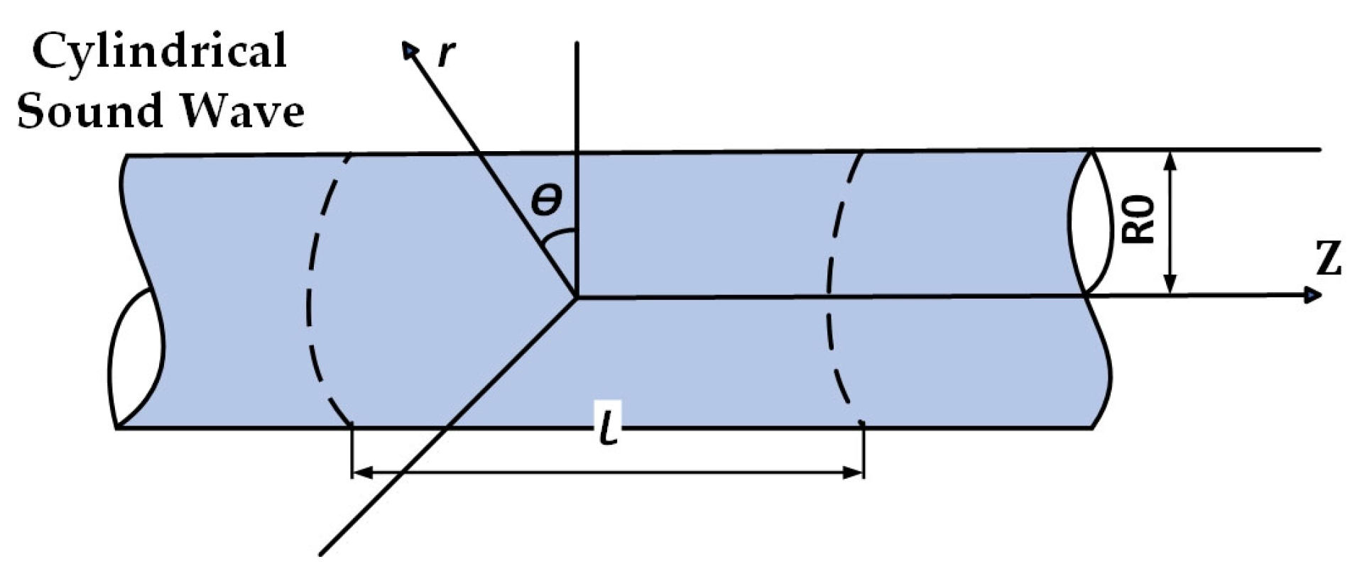
Ignoring the sound radiation from structures such as junction boxes, bases, and end caps, the relative sound intensity coefficient of the motor surface sound radiation can be calculated based on the assumption of an infinitely long cylindrical body. As shown in Figure 12, the calculation of the motor sound power level can be simplified to a two-dimensional problem, enabling the calculation of the relative sound intensity coefficient.
The calculation formula for radiated sound power can be expressed as:
W = 1 2   ρ c ω 2 Y 2 z 2 2 π R 02 l 2 I c l ¯
In the equation, the radiated sound power is related to the propagation medium density ρ , propagation sound velocity C , excitation force angular frequency ω , radial vibration displacement Y 2 z , average shell radius R 02 , shell length l 2 , and relative sound intensity coefficient ( I c l ). Among these, Y 2 z is related to the magnetic parameters, mass parameters, and stiffness parameters of the rotor and stator, and the calculation formula is shown as below.
Y 2 z = 2 π R 11 l 1 B v z B μ z 2 μ 0 K 1 + K 2 ω 2 m 1 + m 2
where B v z and B μ z are the first-order tooth harmonic magnetic fluxes of the stator and rotor, respectively. R 11 is the core radius, l 1 is the core length, μ 0 = 4 π × 10 7 H/m, K 1 and K 2 are the equivalent stiffnesses of the machine housing and core under the action of excitation force, and m 1 and m 2 are the equivalent masses under the action of excitation force.
Finally, the sound power level can be calculated using L W = 10 l g   W / W 0 , where W 0 = 10 12 .

4.5. Sound Radiation Simulation of Total Traction Drive System

Due to the large number of components and relatively complex structure of the physical assembly model of the gearbox, it is necessary to reduce the amount of calculations and avoid errors caused by model damage during simulation by removing chamfers and round corners from the model and simplifying surface features.
Since the gearbox assembly has many components and a relatively complex structure, it is necessary to simplify the model by removing chamfers and round corners and simplifying surface features in order to reduce the amount of computation and avoid unnecessary errors during simulation. The simplified gearbox diagram is shown in Figure 13.
We imported the simplified model into COMSOL software [34] (version 6.2), defined the loads and spring bases at the bearing mounting locations, and additionally defined a spring base at the rubber shaft assembly location described earlier. Based on the previous analysis, the calculated meshing sound intensity data and motor sound power data are imported into point sound sources at the gear meshing position and motor assembly position, respectively. Additionally, bearing excitation caused by gear meshing is applied at the gearbox bearing location. Based on this, a sound-vibration coupling simulation calculation is performed, ultimately yielding the sound field distribution of the traction transmission system. The overall simulation model of the traction drive system is shown in Figure 14.

5. Parametric Impact Analysis of Acoustic Radiation

Based on the calculations from the previous section’s lumped parameter model, it is evident that operating conditions and gear parameters have a significant impact on bearing force excitation. Therefore, this section will focus on analyzing the sound field of the traction drive system in relation to operating conditions and gear parameters. When investigating the effects of helix angle, the operating conditions are selected at the rated speed, i.e., different simulation results under a gear excitation frequency of 1001.3 Hz.

5.1. The Effect of Operating Condition (Speed) on Acoustic Radiation

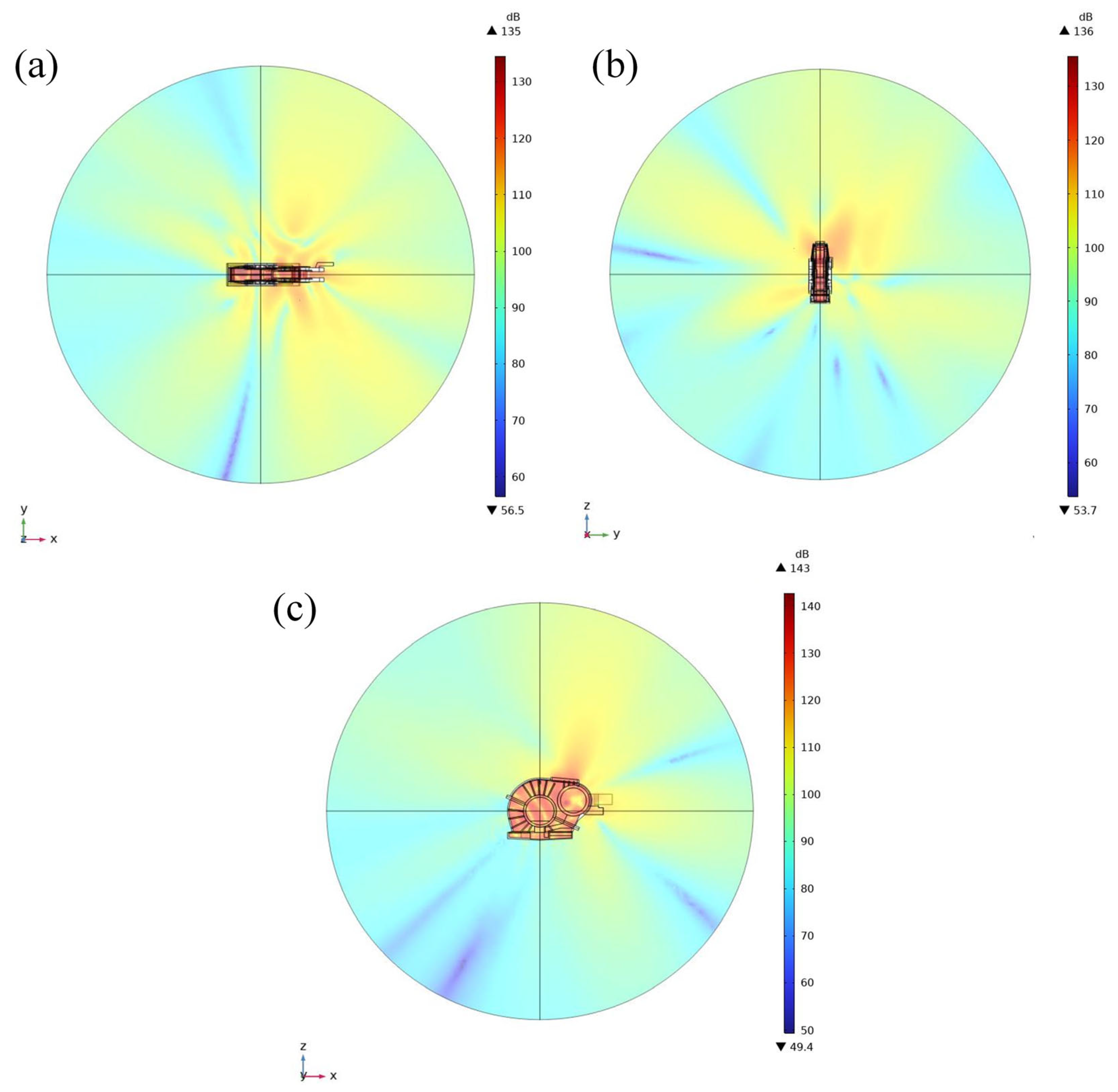
Figure 15 shows the near-field sound pressure level distribution of the traction drive system under working condition 5. It can be seen from the figure that the highest sound pressure level is located inside the box, and the highest sound pressure level distribution in the air domain is located between the motor and the gearbox. The same calculation was performed for the remaining five operating conditions, and the results showed that the near-field distribution of sound pressure levels remained almost unchanged at different speeds.
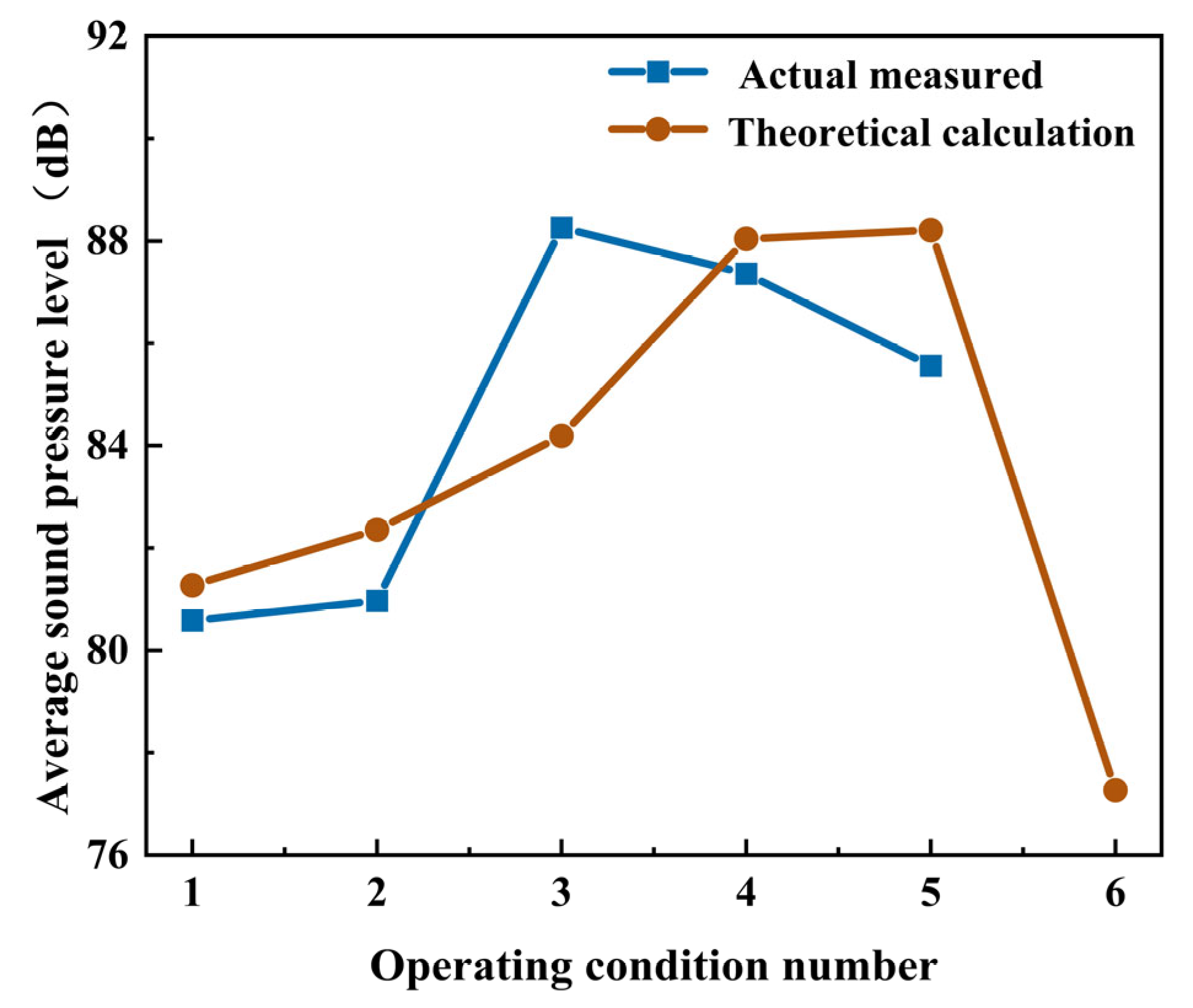
Figure 16 presents the average sound pressure levels at a distance of 4 m from the traction drive system under six different operating conditions (speeds), as calculated by the theoretical model, along with a comparison to measured data obtained from real vehicle tests. It can be observed that as the train speed increases, the total sound pressure level does not rise continuously; instead, it first increases from 81.3 dB to 88 dB and then decreases to 77.3 dB, exhibiting an overall trend of initial increase followed by decrease. This behavior is consistent with the pattern analyzed in Section 4.2, where the excitation force initially rises and then declines with increasing speed. Furthermore, the experimental and theoretical sound pressure level results show general agreement in both magnitude and trend. The maximum error occurs under operating condition 3, with a theoretical value of 84.2 dB and an experimental measurement of 88.3 dB, resulting in an error within 5%.
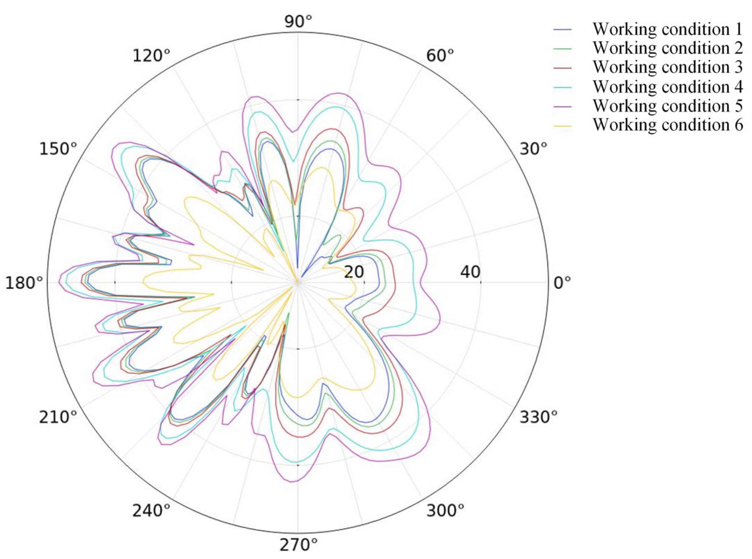
To observe the far-field noise propagation characteristics of the gear transmission system more intuitively, a spherical surface at a distance R = 12 m from the gearbox was selected as the calculation surface. The sound pressure level radiation direction diagrams in the XY plane under different operating conditions are shown in Figure 17. It is evident that the distribution of the external sound pressure level is primarily radiated outward from the gearbox panel, with the largest radiation occurring in the negative direction of the X-axis, while the remaining directions exhibit regular fluctuations. Under different operating conditions, the overall radiation direction pattern of the external sound pressure level remains largely unchanged, but there is a numerical variation where the sound pressure level first increases and then decreases as the operating speed increases, consistent with the conclusions from the previous analysis.

5.2. The Effect of Helix Angle on Acoustic Radiation

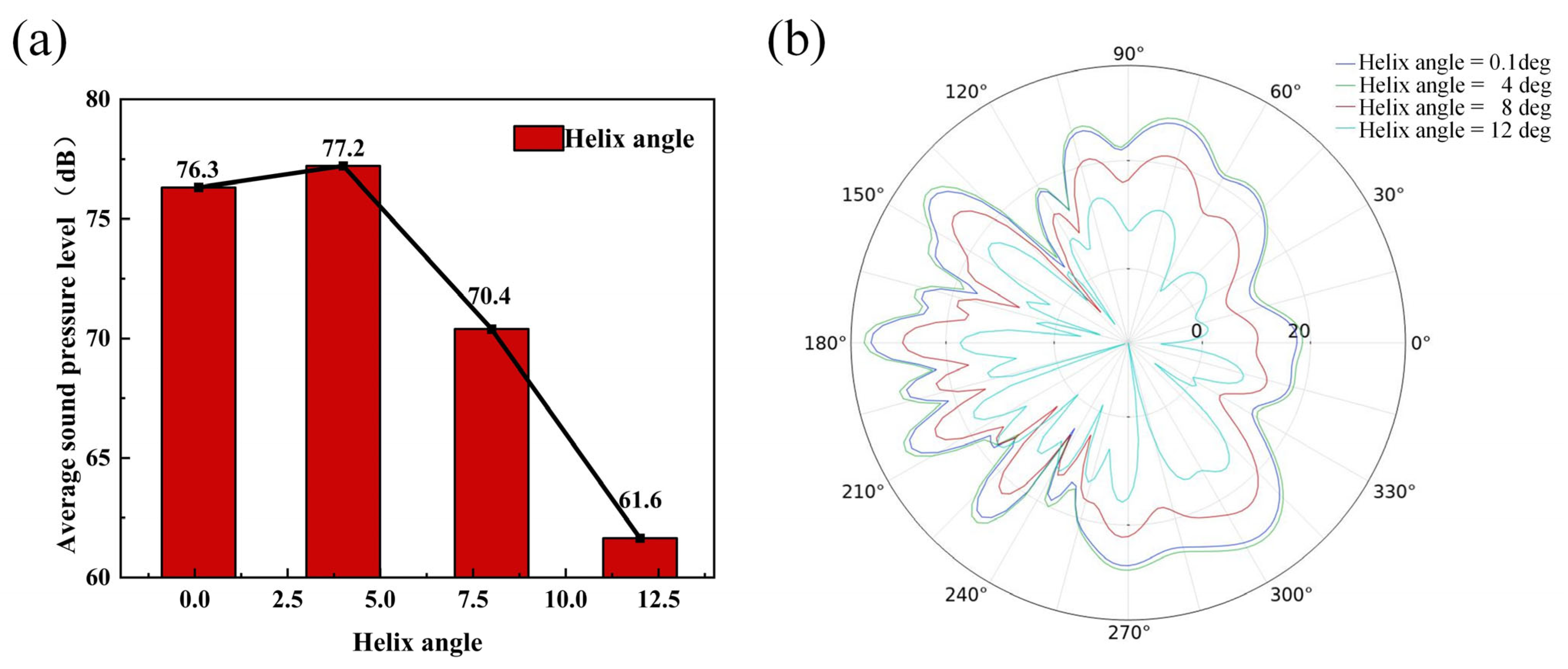
The near-field sound pressure level distribution of the traction drive system was calculated for four different helix angle parameters ( 0.1 ° ,   4 ° ,   8 ° ,   and   12 ° ) . The results show that the sound pressure level distribution of the system remains basically unchanged at different helix angles. Figure 18a shows the average sound pressure level of the system at a distance of 4 m under different helix angles. It can be observed that under different helix angles, the average sound pressure level in the outer field first increases slightly and then decreases significantly as the helix angle increases. A spherical surface at a distance of R = 12 m from the gearbox was selected as the calculation surface. The XY-plane radiation directions of the far-field sound pressure levels under different helix angles are shown in Figure 18b. It can be observed that the radiation trends of the sound pressure in the external field under the four different helix angle conditions are basically consistent, with only differences in the sound pressure level values. It can be seen that the sound pressure level first increases and then decreases with the increase in the meshing angle, consistent with the conclusions from the previous discussion.

6. Conclusions

This paper proposes a rapid modeling method for sound radiation from locomotive traction drive systems. The approach employs a lumped parameter model for the gear system, combined with theoretical models of motor and gear meshing noise, to simplify the modeling and computational process of system sound radiation. This simplification significantly reduces complexity and enables efficient acoustic simulation of the traction drive system under various operating conditions. Based on the comparison in Figure 16 and the analysis in Section 5.1, the computational results obtained by the proposed method show strong agreement with noise data measured from actual traction systems, with a maximum error not exceeding 5%, thereby verifying its reliability. Furthermore, compared to conventional direct finite element modeling methods, the proposed approach maintains solution accuracy while eliminating the need for finite element computation of the gear meshing process, substantially reducing computational time. This improvement facilitates a more detailed analysis of the intrinsic relationships between design parameters and dynamic responses, ultimately supporting the identification of noise reduction strategies at the source.
The experimental results indicate that the primary noise sources in the transmission system vary with operating conditions. According to the analysis in Section 3.2, under high-speed operating conditions—exemplified by Condition 5—the noise characteristic frequencies include gearbox vibration frequencies at 527 Hz and 1032 Hz, while only the motor vibration frequency at 1032 Hz is present. Thus, it can be concluded that the gearbox is the dominant noise source. In contrast, under low-speed conditions—exemplified by Condition 2—the noise characteristic frequencies contain motor characteristic frequencies at 933 Hz, 1857 Hz, and 2780 Hz, while only the gearbox vibration frequency at 933 Hz is present, indicating that the motor is the main contributor to noise. Parameter influence analysis reveals that variations in train operating speed and gear helix angle significantly affect the sound pressure level of the traction drive system. Within the parameter range selected in this study, these variations cause a difference of approximately 10 dB between the upper and lower extreme values of the sound pressure level while having minimal impact on noise distribution and radiation direction. Notably, as shown in Figure 16 and Figure 18, as the train operating speed and gear helix angle increase, the noise level of the traction drive system initially increases and then decreases.

Author Contributions

C.L. and X.L.: conceptualization, methodology, software, investigation, formal analysis, writing—original draft. K.Y. and Z.Y.: data curation, writing—original draft, visualization, investigation. J.Z. and P.L.: conceptualization, resources, supervision, writing—review and editing. All authors have read and agreed to the published version of the manuscript.

Funding

This work was supported by the National Natural Science Foundation of China (Grant No. 52275092) and the SEU Innovation Capability Enhancement Plan for Doctoral Students (No. CXJH_SEU 25059).

Institutional Review Board Statement

Not applicable.

Informed Consent Statement

Not applicable.

Data Availability Statement

The original contributions presented in this study are included in the article. Further inquiries can be directed to the corresponding author.

Conflicts of Interest

Authors Chao Li and Xiaobo Liu were employed by the company CRRC Zhuzhou Locomotive Co., Ltd. The remaining authors declare that the research was conducted in the absence of any commercial or financial relationships that could be construed as a potential conflict of interest.

References

  1. Ma, J.; Luo, C.; Qiu, L.; Liu, X.; Xu, B.; Shou, J.; Fang, Y. Recent advances in traction drive technology for rail transit. J. Zhejiang Univ. A 2023, 24, 177–188. [Google Scholar] [CrossRef]
  2. Polater, N.; Tricoli, P. Technical Review of Traction Drive Systems for Light Railways. Energies 2022, 15, 3187. [Google Scholar] [CrossRef]
  3. Morgado, T.; Branco, C.; Infante, V. A failure study of housing of the gearboxes of series 2600 locomotives of the Portuguese Railway Company. Eng. Fail. Anal. 2008, 15, 154–164. [Google Scholar] [CrossRef]
  4. Ye, Z.; Chen, Z.; Zhou, Z.; Zhai, W. Dynamic modelling of locomotive with direct drive traction system considering electromechanical coupling effect. Veh. Syst. Dyn. 2024, 62, 1756–1779. [Google Scholar] [CrossRef]
  5. Poliakov, N.; Arbuzina, A.; Arkharova, M. Four Quadrant AC-DC Converter Control System Prototype for AC Locomotive Traction Drive. In Proceedings of the 2023 IEEE 24th International Conference of Young Professionals in Electron Devices and Materials (EDM), Novosibirsk, Russia, 29 June–3 July 2023; pp. 1670–1675. [Google Scholar]
  6. Burkov, A.T.; Valinsky, O.S.; Evstaf’eV, A.M.; Maznev, A.S.; Tretyakov, A.V. Modern Locomotive Traction Drive Control Systems. Russ. Electr. Eng. 2019, 90, 692–695. [Google Scholar] [CrossRef]
  7. Lu, B.; Song, Y.; Liu, Z.; Tao, G.; Wang, X.; Zhang, Q.; Li, Z. Evolution analysis of wheel polygon wear considering the effect of interharmonics in electrical traction drive system. Mech. Mach. Theory 2024, 191, 105470. [Google Scholar] [CrossRef]
  8. Bao, J.; Tian, Y.; Zheng, L.; He, W. Dynamic simulation and fatigue life prediction of locomotive traction drive system. J. Comput. Methods Sci. Eng. 2024, 24, 4128–4142. [Google Scholar] [CrossRef]
  9. Buynosov, A.; Sergeev, B.; Kalinichenko, A.; Antropov, S. Development of an Automatic Locomotive Traction Drive Control System to Reduce the Amount of Wheel Slippage on the Rail. In Proceedings of the VIII International Scientific Siberian Transport Forum, Novosibirsk, Russia, 22–27 May 2019; Springer Science and Business Media Deutschland GmbH: Cham, Switzerland, 2020. [Google Scholar]
  10. Antipin, D.Y.; Vorobiyov, I.; Izmerov, O.V.; Shorokhov, S.G.; Bondarenko, D.A. Friction Self-Oscillation Decrease in Nonlinear System of Locomotive Traction Drive; IOP Publishing Ltd.: Tomsk, Russia, 2017. [Google Scholar]
  11. Antipin, D.Y.; Izmerov, O.V.; Kopyilov, O.S. Influence of Locomotive Traction Drive Design on Main Forms of Self-Oscillations During Spinning; IOP Publishing Ltd.: Saint-Petersburg, Russia, 2017. [Google Scholar]
  12. Zhou, Z.; Chen, Z.; Spiryagin, M.; Wolfs, P.; Wu, Q.; Zhai, W.; Cole, C. Dynamic performance of locomotive electric drive system under excitation from gear transmission and wheel-rail interaction. Veh. Syst. Dyn. 2022, 60, 1806–1828. [Google Scholar] [CrossRef]
  13. Wu, G.; Shen, L.; Yao, Y.; Song, W.; Huang, J. Determination of the dynamic characteristics of locomotive drive systems under re-adhesion conditions using wheel slip controller. J. Zhejiang Univ. A 2023, 24, 722–734. [Google Scholar] [CrossRef]
  14. Ren, B.; Liu, P.; Yang, S.; Song, W. Locomotive Drive System Fault Diagnosis Based on Dynamic Self-Adaptive Blind Source Separation. In Proceedings of the First International Conference on Rail Transportation, Chengdu, China, 10–12 July 2017; pp. 736–744. [Google Scholar]
  15. Zhao, Y.; Li, Q.; Yang, J.; Liu, C.; Wang, J. A Lagrangian approach for the railway vehicle with gear system coupled model considering wheel polygonal faults under traction conditions. J. Vib. Control. 2024, 30, 1339–1352. [Google Scholar] [CrossRef]
  16. Zhang, T.; Chen, Z.; Zhai, W.; Wang, K. Establishment and validation of a locomotive–track coupled spatial dynamics model considering dynamic effect of gear transmissions. Mech. Syst. Signal Process. 2019, 119, 328–345. [Google Scholar] [CrossRef]
  17. Wu, P.; Song, C.; Wang, X.; Qu, S.; Wu, H. Vibration Analysis of Traction Drive System Components Based on the Field Test for High-Speed Train. J. Adv. Transp. 2023, 2023, 1–10. [Google Scholar] [CrossRef]
  18. Zhang, K.; Yang, J.; Liu, C.; Wang, J.; Yao, D. Dynamic Characteristics of a Traction Drive System in High-Speed Train Based on Electromechanical Coupling Modeling under Variable Conditions. Energies 2022, 15, 1202. [Google Scholar] [CrossRef]
  19. Wang, X.; Qu, S.; Wu, P.; Zeng, J. Influence of beat frequency excitation on the traction drive system in high-speed train under electromechanical coupling. J. Vib. Control. 2025, 1–14. [Google Scholar] [CrossRef]
  20. Thompson, D. Chapter 14—Vehicle Interior Noise. In Railway Noise and Vibration, 2nd ed.; Thompson, D., Ed.; Elsevier: Amsterdam, The Netherlands, 2024; pp. 643–684. [Google Scholar]
  21. Soeta, Y.; Shimokura, R. Survey of interior noise characteristics in various types of trains. Appl. Acoust. 2013, 74, 1160–1166. [Google Scholar] [CrossRef]
  22. Sapena, J.; Tabbal, A.; Jove, J.; Guerville, F. Interior noise prediction in high-speed rolling stock driver’s cab: Focus on structure-borne paths (mechanical and aero sources). In Noise and Vibration Mitigation for Rail Transportation Systems, Proceedings of the 10th International Workshop on Railway Noise, Nagahama, Japan, 18–22 October 2010; Maeda, T., Gautier, P., Hanson, C.E., Hemsworth, B., Nelson, J.T., Schulte-Werning, B., de Vos, P., Eds.; Springer: Tokyo, Japan, 2012; pp. 445–452. [Google Scholar]
  23. Huang, S.; Aydin, M.; Lipo, T.A. Electromagnetic vibration and noise assessment for surface mounted PM machines. In Proceedings of the 2001 Power Engineering Society Summer Meeting, Conference Proceedings (Cat. No.01CH37262), Vancouver, BC, Canada, 15–19 July 2001; pp. 1417–1426. [Google Scholar]
  24. Blum, J.; Merwerth, J.; Herzog, H.-G. Investigation of the segment order in step-skewed synchronous machines on noise and vibration. In Proceedings of the 2014 4th International Electric Drives Production Conference (EDPC), Nuremberg, Germany, 30 September–1 October 2014; pp. 1–6. [Google Scholar]
  25. Torregrossa, D.; Peyraut, F.; Cirrincione, M.; Espanet, C.; Cassat, A.; Miraoui, A. A New Passive Methodology for Reducing the Noise in Electrical Machines: Impact of Some Parameters on the Modal Analysis. IEEE Trans. Ind. Appl. 2010, 46, 1899–1907. [Google Scholar] [CrossRef]
  26. Yuan, B.; Chang, L.; Liu, G.; Chang, S.; Liu, L.; Shen, Y. An efficient three-dimensional dynamic contact model for cylindrical gear pairs with distributed tooth flank errors. Mech. Mach. Theory 2020, 152, 103930. [Google Scholar] [CrossRef]
  27. Li, F.; Jiao, H.; Zhang, J.; Fu, Q. Dynamic Modeling and Output Characteristics Analysis of the Hub-Drive Reduction System. Appl. Sci. 2025, 15, 1680. [Google Scholar] [CrossRef]
  28. Adams, version 2020. Software for Multibody Dynamics Simulation. MSC Software Corporation: Newport Beach, CA, USA, 2020.
  29. MATLAB, version R2023b. Software for Numerical Computing. The MathWorks, Inc.: Natick, MA, USA, 2023.
  30. Wu, H.; Wu, P.; Li, F.; Shi, H.; Xu, K. Fatigue analysis of the gearbox housing in high-speed trains under wheel polygonization using a multibody dynamics algorithm. Eng. Fail. Anal. 2019, 100, 351–364. [Google Scholar] [CrossRef]
  31. Fernandez-Del-Rincon, A.; Diez-Ibarbia, A.; Theodossiades, S. Gear transmission rattle: Assessment of meshing forces under hydrodynamic lubrication. Appl. Acoust. 2019, 144, 85–95. [Google Scholar] [CrossRef]
  32. Theodossiades, S.; De la Cruz, M.; Rahnejat, H. Prediction of airborne radiated noise from lightly loaded lubricated meshing gear teeth. Appl. Acoust. 2015, 100, 79–86. [Google Scholar] [CrossRef]
  33. Masuda, T.; Abe, T.; Hattori, K. Prediction Method of Gear Noise Considering the Influence of the Tooth Flank Finishing Method. J. Vib. Acoust. Trans. ASME 1986, 108, 95–100. [Google Scholar] [CrossRef]
  34. COMSOL Multiphysics, version 6.2. Software for Multiphysics Simulation. COMSOL AB: Stockholm, Sweden, 2023.
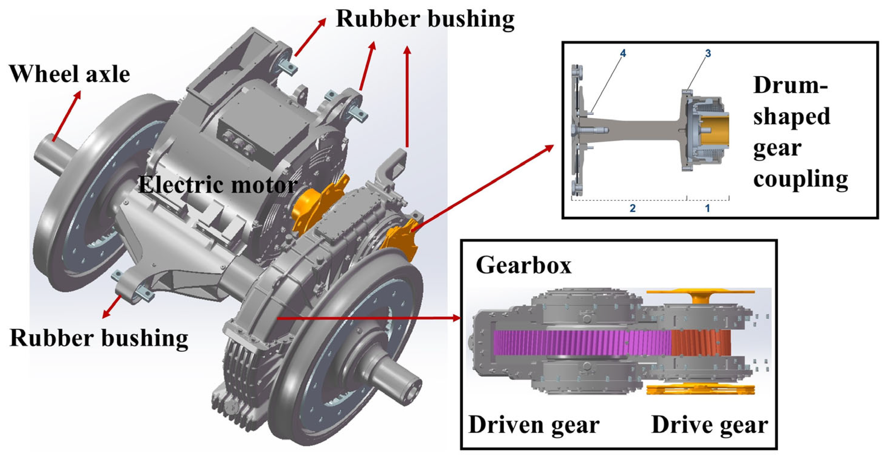
Figure 1. Schematic diagram of locomotive traction system. (1. Drum Gear Coupling; 2. Flexible Disc Coupling; 3. Connecting Bolts for Drum Gear Coupling and Drive Shaft; 4. Connecting Bolts for Flexible Disc Coupling and Gearbox).
Applsci 15 10597 g001
Figure 2. Schematic diagram of the installation position of acceleration and acoustic sensors.
Applsci 15 10597 g002
Figure 3. Spectrum of vibration and acoustic signals for operating condition 1. (a) Motor Vibration Signal (b) Motor Acoustic Signal (c) Gearbox Vibration Signal (d) Gearbox Acoustic Signal (Different scale factors have been applied to the figures).
Applsci 15 10597 g003
Figure 4. Rapid modeling process for traction drive system acoustic radiation.
Applsci 15 10597 g004
Figure 5. Simplified diagram of a 2-node 8-degree-of-freedom gear dynamic model.
Applsci 15 10597 g005
Figure 6. Change in contact line length on single teeth.
Applsci 15 10597 g006
Figure 7. Load and boundary conditions in ADAMS model.
Applsci 15 10597 g007
Figure 8. Time domain and frequency domain results of input torque.
Applsci 15 10597 g008
Figure 9. Bearing dynamic excitation spectrum under operating condition 5. (Different scale factors have been applied to the figures).
Applsci 15 10597 g009
Figure 10. Three-directional load on the bearings of the (a) drive gear and (b) driven gear under different operating conditions. (Different scale factors have been applied to the figures).
Applsci 15 10597 g010
Figure 11. Time domain diagram of dynamic gear transmission error.
Applsci 15 10597 g011
Figure 12. Simplified schematic diagram of motor cylindrical shell.
Applsci 15 10597 g012
Figure 13. Simplified schematic diagram of gearbox model.
Applsci 15 10597 g013
Figure 14. Overall simulation model of the traction drive system.
Applsci 15 10597 g014
Figure 15. Near-field sound pressure level distribution diagram in (a) XY plane, (b) XZ plane, and (c) YZ plane under operating condition 5 (Different scale factors have been applied to the figures).
Applsci 15 10597 g015
Figure 16. Average sound pressure level at 4 m from the traction drive system under different operating conditions.
Applsci 15 10597 g016
Figure 17. Radiation direction diagram of sound pressure level in the XY plane under six working conditions.
Applsci 15 10597 g017
Figure 18. (a) Average sound pressure level and (b) radiation direction diagram in the XY plane under four helix angles.
Applsci 15 10597 g018
Table 1. Sound and vibration test conditions.
Working Conditions12345
Travel speed20 km/h30 km/h40 km/h50 km/h60 km/h
Theoretical motor speed338.65 rpm507.97 rpm677.30 rpm846.61 rpm1015.90 rpm
Calculated meshing frequency174.97 Hz262.45 Hz349.94 Hz437.42 Hz524.90 Hz
Table 2. Noise and vibration characteristic frequencies under different working conditions.
Working Conditions12345
Motor vibration frequency (Hz)510
926
1852
2743
933
1857
2780
705
1207
2453
1131
2468
705
1032
Gearbox vibration frequency (Hz)371
530
926
266
520
933
350
705
462
918
1387
527
1031
Noise characteristic frequency (Hz)926
1852
2778
933
1857
2780
1207
2453
463
918
1132
1387
527
1032
1594
2112
Table 3. Basic parameters of gears.
ParametersDriving WheelDriven Wheel
Module7.35
Number of teeth31104
Tooth profile angle20°
Tooth top height coefficient1.2
Top clearance coefficient0.35
Normal displacement coefficient0.27807−0.59026
Helix angle
Center distance495
Table 4. Locomotive operating conditions in this paper.
Operating ConditionsTrain Speed (km/h)Meshing Frequency (Hz)
120174.97
230262.45
340349.94
450437.42
560524.9
61141001
Table 5. Gear meshing noise under different operating conditions.
Working ConditionsTrain Speed (km/h)Excitation Frequency (Hz)Sound Pressure Level (dB)
120174.9770.7811
230262.4585.5865
340349.9484.9987
450437.4292.8384
560524.993.6556
6114100188.5417
Disclaimer/Publisher’s Note: The statements, opinions and data contained in all publications are solely those of the individual author(s) and contributor(s) and not of MDPI and/or the editor(s). MDPI and/or the editor(s) disclaim responsibility for any injury to people or property resulting from any ideas, methods, instructions or products referred to in the content.