Abstract
Precise time synchronization is indispensable for enabling seamless coordination in Intelligent Transportation Systems (ITS) which rely on reliable vehicle communications. This work introduces lightweight online clock skew compensation algorithms based on Recursive Least Squares (RLS) and Recursive Weighted Least Squares (RWLS) techniques tailored for ITS time synchronization. Unlike traditional approaches relying on offline batch processing and large-scale data storage, the proposed algorithms continuously update clock skew estimates immediately upon receiving each timing sample, thereby significantly reducing memory requirements. These methods are applicable to Vehicle-to-Vehicle (V2V), Vehicle-to-Infrastructure (V2I), and Infrastructure-to-Infrastructure (I2I) communication scenarios, offering a cost-effective software solution to improve synchronization accuracy. Extensive simulations and experimental validations demonstrate that the developed estimators effectively minimize skew-related timing errors, thereby enhancing the robustness and precision of vehicular network timekeeping.
1. Introduction
Time synchronization plays a crucial role in enabling cooperative functions within vehicular networks and infrastructure systems [1,2,3]. Distributed nodes such as vehicles’ On-Board Equipment (OBE), roadside units (RSUs), and backbone infrastructure components must maintain consistent timing to coordinate communication slots, support safety-critical applications, and achieve seamless data fusion. In Intelligent Transportation Systems (ITS), the primary communication paradigms include Vehicle-to-Vehicle (V2V), Vehicle-to-Infrastructure (V2I), and Infrastructure-to-Infrastructure (I2I) interactions, each imposing stringent timing requirements to minimize collisions, latency, and operational errors [2,4,5,6].
Global Navigation Satellite System (GNSS)-based synchronization serves as the predominant source of absolute time reference for many ITS deployments [3,7]. However, GNSS signals are susceptible to blockage due to urban canyons, tunnels, or adverse weather, and clock frequency deviations in local oscillators induce cumulative timing errors over time, known as clock skew, which degrades the synchronization quality between GNSS fixes [8].
Traditional synchronization protocols predominantly focus on correcting clock offsets, frequently overlooking skew compensation or relying on methods that entail high computational complexity or require additional hardware [8,9]. Effectively and efficiently addressing clock skew remains a critical challenge to improve the robustness and precision of time synchronization in vehicular and infrastructure networks [1,10].
This paper introduces a lightweight online clock skew compensation algorithm designed for easy integration into existing clock offset correction frameworks applicable to V2V, V2I, and I2I communication settings. The proposed method achieves significant improvements in accuracy by compensating skew with minimal computational burden, thus enhancing overall synchronization fidelity and contributing to improved communication reliability and system robustness in ITS environments.
To clearly outline the novelty and practical significance of this study, the main contributions of this work are summarized as follows:
- This paper proposes lightweight online clock skew estimation algorithms that update skew in real time with minimal storage and computation.
- This paper integrates the proposed estimators into existing offset correction frameworks, enabling accurate and hardware-free synchronization in ITS scenarios.
- This paper validates the effectiveness of the proposed approach through simulations and testbed experiments, demonstrating significant error reduction in both single-hop and multi-hop networks.
The structure of the remainder of this paper is as follows. Section 2 provides an overview of related work. Section 3 introduces fundamental concepts of time synchronization, while Section 4 details the development of online clock skew estimation methods. Section 5 describes the implementation issues of the proposed skew compensation scheme. In Section 6, simulation and experimental results are provided for performance evaluation. Finally, Section 7 concludes the paper. For clarity, the key symbols and notations used throughout this paper are summarized in Table 1.

Table 1.
Key symbol definitions and notations.
2. Related Work
Time synchronization is a fundamental component of ITS, ensuring coordinated operations among vehicles, RSUs, and broader infrastructure networks. As shown in Figure 1, ITS encompasses multiple communication paradigms, including V2V, V2I, and I2I interactions, each requiring precise and reliable synchronization mechanisms to support safety-critical applications, efficient channel access, and consistent data fusion [1,2,3]. Furthermore, accurate time synchronization is essential for localization, as it directly enables high-precision and dependable positioning within ITS environments [11,12].
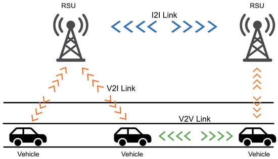
Figure 1.
Three communication links in ITS: V2V, V2I, and I2I.
2.1. ITS Synchronization: I2I and V2I Scenarios
In ITS, I2I time synchronization is essential for coordinating RSUs to ensure slot-aligned communication across the network and to support reliable V2I interactions. GNSS-based synchronization has been widely adopted as a primary absolute time reference source due to its global coverage and high precision, leveraging a constellation of satellites equipped with atomic clocks synchronized to Universal Time Coordinated (UTC) [1,13,14].
Recent advances have significantly improved GNSS timing performance and robustness. In [13], it is proposed that enhanced short-term stability estimation techniques for real-time GNSS satellite clocks using advanced clock modeling and carrier phase observations, achieving timing accuracy superior to previous ground-based estimations. This addresses clock instability and deterministic errors affecting satellite time signals in orbit. Complementing this, ref. [14] introduced a novel weighting model that exploits Global Positioning System (GPS) signal strength variability to improve satellite positioning accuracy in urban canyon scenarios. This approach mitigates typical multipath and signal blockage effects, thereby enhancing positioning and timing reliability in challenging environments. Collectively, these studies demonstrate how refined clock modeling and signal processing can overcome the limitations of classical GNSS by improving timing stability and positioning accuracy.
Nonetheless, GNSS still faces fundamental constraints that cannot be fully eliminated. Signal blockage in tunnels and adverse weather, as well as multipath propagation, degrade its reliability in many ITS scenarios. Moreover, advanced correction schemes often add cost and computational burden [11,15]. As a result, complementary methods remain essential to ensure resilient synchronization in diverse operating environments [1,3,8,15].
To address these challenges, the ITS standard [16] specifies an Over-The-Air (OTA) synchronization mechanism in the 700 MHz band, where RSUs periodically transmit timestamped packets within a Time Division Multiple Access (TDMA) frame. This OTA framework provides continuous timing corrections and microsecond-level accuracy, ensuring coherent operation among infrastructure components and vehicles even when GNSS signals are impaired. At the same time, recent work confirms that GNSS-only synchronization deteriorates sharply in urban canyons, whereas OTA support sustains precise timing [11]. Collectively, these insights highlight the importance of hybrid synchronization strategies that exploit the global accuracy of GNSS together with the local reliability of OTA broadcasts, thereby enabling robust and efficient timekeeping in practical ITS deployments.
2.2. Time Synchronization: V2V Scenarios (VANET Environments)
Vehicular Ad Hoc Networks (VANETs), which primarily facilitate V2V communication and contribute to V2I interactions, present distinctive challenges for time synchronization due to their highly dynamic topology and the mobility of nodes. The external environment, particularly urban areas with dense buildings and complex propagation characteristics, further complicates synchronization accuracy requirements. As extensively presented by Hasan et al. in [1], VANETs require synchronization precision on the order of microseconds to milliseconds to support real-time safety applications such as cooperative collision warnings, platooning, and emergency message dissemination. Comprehensive survey studies have also analyzed the security and reliability aspects of VANET time synchronization, emphasizing the importance of accurate timing in maintaining secure and resilient vehicle networks [9,17]. Recent work has expanded on the requirements for high-precision synchronization in Device-to-Device and V2V-enabled cellular networks, discussing both protocol evolution and inherent performance bounds in practical deployments [18]. Building on these insights, a high-precision time synchronization algorithm has also been proposed for UAV ad hoc networks using bidirectional pseudo-range measurements, illustrating the applicability of advanced synchronization strategies to dynamic, multi-hop vehicular environments facing similar challenges of mobility and channel impairments [19].
Clock synchronization in Wireless Sensor Networks (WSNs) has been extensively studied, resulting in the development of numerous protocols that, despite varying implementations, share core synchronization principles [20,21,22,23]. These protocols synchronize the nodes primarily by exchanging timestamp information, while actively minimizing the influence of nondeterministic delays during message transmission. Typically, these synchronization methods are categorized into three main types, as illustrated in Figure 2: sender-receiver (S-R) synchronization, receiver-receiver (R-R) synchronization, and unidirectional (one-way) message dissemination. These have been adapted for VANET use due to their effective clock offset correction approaches. However, these approaches often underrepresent clock skew compensation, which is critical in VANETs given oscillator frequency drifts causing cumulative timing errors over time.
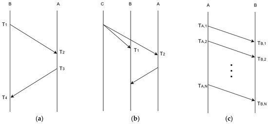
Figure 2.
Basic synchronization approaches, where A is the reference node, and B synchronizes with A’s time: (a) S-R synchronization; (b) R-R synchronization, where C acts as the beacon node; (c) One-way message dissemination.
S-R synchronization mechanism is implemented through a bidirectional handshake between two nodes, exemplified by the Timing-sync Protocol for Sensor Networks (TPSN) [20]. As shown in Figure 2a, Node B sends a message timestamped at its local clock time T1, which is received by Node A at time T2. At time T3, Node A replies with an acknowledgment containing timestamps T2 and T3. When the packet is received by Node B at T4, the clock offset and propagation delay are determined according to Equation (1). Using the estimated offset, Node B adjusts its local clock to synchronize with Node A’s clock.
In R-R synchronization, a beacon node (Node C) periodically broadcasts beacon messages as depicted in Figure 2b. Receiving nodes timestamp the arrival of these broadcasts with their local clocks and exchange these timestamps among themselves. Node B, by comparing its reception time T2 to Node A’s reception time T1, calculates the relative clock offset (T2 − T1) and synchronizes accordingly. Reference Broadcast Synchronization (RBS) [21] is a typical example of this synchronization method.
The third approach, one-way message dissemination, involves a reference node (Node A) broadcasting its timing information to neighboring nodes, as shown in Figure 2c. The other nodes record the reception times and, by gathering multiple timestamps, construct linear regression models to translate local hardware clocks to the reference clock. The Flooding Time Synchronization Protocol (FTSP) [22] is a key protocol employing this unidirectional dissemination approach.
3. Clock Models and Challenges in Time Synchronization
This section focuses on establishing a general clock model that captures the behavior of realistic oscillators, including their offset and frequency drift characteristics. Additionally, it discusses how clock skew poses significant challenges in maintaining a consistent notion of time across the network.
3.1. Clock Fundamentals
A clock device is generally composed of an oscillator that produces periodic signals and a counter that accumulates these signals to represent elapsed time [23]. The nominal frequency of the oscillator governs the clock’s progress rate. However, due to manufacturing variances and environmental influences, no two clocks generate pulses at identical frequencies. Such differences give rise to timing discrepancies.
The reported time by a clock at an ideal time t is denoted as C(t). Specifically, CA(t) represents the time indicated by the local clock of Node A. The difference between this ideal reference time and the time measured by a particular clock is termed the offset, denoted as θ(t), which is formally defined as
The relative offset between two nodes, Node A and Node B, observed from the perspective of Node B, is expressed as
Clocks operate based on oscillators that generate periodic pulses. The deviation between the pulse frequency of a given clock and that of an ideal reference clock is referred to as skew or frequency offset. Denoting skew by ε(t), it is characterized as
Unlike some earlier studies [1,24,25,26], which define the clock skew as ε(t) = C′(t) − 1, the formulation used in this study differs only in the choice of reference point. The difference is straightforward: because the clock being adjusted is not an ideal reference clock but rather an individual node’s clock, the skew is defined from the perspective of each node. It does not affect the fundamental nature of skew but reflects a change in viewpoint.
In this context, clock skew corresponds to the rate of change in the offset relative to the local clock. Similarly, the relative skew between two nodes quantifies the slope of the relative offset, representing the frequency difference in Node A’s clock as viewed from Node B’s clock:
Typical quartz oscillators exhibit frequency deviations on the order of several PPM. For instance, an oscillator with a 20 PPM frequency offset may accumulate an error of up to approximately 72 ms over the course of one hour. For the purposes of this study, a linear clock skew model was adopted, assuming that skew values ε are time-invariant over intervals of interest. Although skew can vary with time [24], treating it as a piecewise linear function is often a reasonable approximation since these variations generally occur slowly [25].
Denoting the operating frequencies of Node A and Node B as fA and fB respectively, fA can be expressed in terms of fB as
and, accordingly, the relative skew admits an alternative formulation:
This modeling framework allows for the effective characterization of clock behavior necessary for accurate synchronization in distributed communication systems.
3.2. Time Synchronization
Time synchronization entails aligning the clocks of multiple nodes, interconnected via either single-hop or multi-hop wireless communication links in VANETs or ITS. Generally, achieving synchronization encompasses a two-step procedure: first, the adjustment of clock offsets among nodes to establish a unified absolute time reference, and second, the correction of clock skew relative to an established nominal frequency. The necessity for skew correction arises from the intrinsic imperfections in quartz oscillators and varying environmental conditions, which cause individual clocks to operate at slightly divergent frequencies. Clock skew is a principal factor leading to ongoing drift in clock offsets over time [1,27]. By mitigating skew, long-term synchronization stability is enhanced, thereby reducing the overall energy expenditure associated with synchronization protocols across the network.
Figure 3 illustrates the process wherein Node B synchronizes its clock with that of Node A. For conceptual simplicity, it is presumed that both clocks start from identical initial values. However, due to unique oscillator frequencies at each node, the clock offset between the two nodes progressively increases. When Node B computes the relative offsets and applies offset compensation at time instances t1, t2, t3, and t4, its synchronized clock is represented as . Because this approach overlooks clock drift, CB(t) steadily diverges from CA(t) at a fixed rate. Extending the interval between synchronization events increases the resultant error. However, excessively frequent synchronization incurs significant communication and energy overhead, hence it is often undesirable despite improved accuracy.
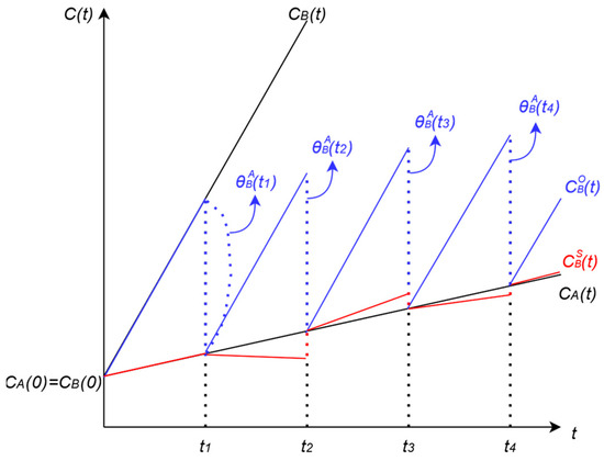
Figure 3.
Illustration of clock offset and skew compensation. For modeling simplicity, skew variation over the depicted time interval is assumed to be negligible, reflecting an idealized clock assumption.
An accurate estimation of the relative clock skew allows the synchronized clock to more closely approximate the reference clock , as depicted in Figure 3, even though perfect synchronization remains unattainable. Nonetheless, precise skew estimation is challenging owing to multiple factors, including transient influences such as fluctuations in supply voltage, temperature variability, humidity changes, as well as long-term effects like oscillator aging. Offset compensation primarily supports short-term synchronization accuracy, whereas skew compensation is instrumental for maintaining long-term synchronization accuracy. Consequently, integrating both offset and skew compensation strategies is essential for developing time synchronization algorithms that reconcile high accuracy with acceptable communication overhead.
The estimation of clock skew is commonly approached via linear regression, which necessitates that each node retains a set of historical synchronization data points [21,27,28]. Expanding the dataset for the least squares estimator generally leads to improved skew estimation accuracy. For example, the Tiny-Sync protocol employs only two timestamps, resulting in minimal storage overhead but yielding suboptimal estimation performance [28]. Conversely, Mini-Sync attains much more reliable skew estimation, though it requires the collection of over 40 data samples. Similarly, effective linear regression within the RBS protocol typically requires approximately 30 previous synchronization records [21]. Given the limited memory and computational resources of nodes, high memory and computational complexity in skew estimation algorithms is generally impractical. Moreover, such linear regression-based estimations are traditionally performed offline—skew is estimated only after a sufficiently large set of offset samples has been gathered.
Recent studies have approached synchronization challenges through a view of statistical signal processing, as comprehensively reviewed in [23]. Early statistical methods for joint skew/offset estimation provided rigorous performance analyses in wireless environments [26]. Building upon this foundation, one-way broadcast-based Maximum Likelihood Estimators (MLE) have been developed to model delay statistics explicitly and to derive Cramér–Rao bounds for clock skew estimation, thereby improving robustness under dynamic wireless conditions [29]. While the application of the Kalman filter enables clock behavior tracking based on general clock models, embedding such filters in resource-constrained nodes is often infeasible due to their computational and algorithmic complexity [24,30].
It is hence essential that time synchronization schemes simultaneously compensate for both offset and skew. In alignment with this principle, this paper proposes novel lightweight online clock skew estimation algorithms that can be seamlessly integrated with established offset compensation schemes, such as TPSN, RBS, and FTSP. By employing recursive least squares (RLS) for real-time skew estimation and update at each new offset measurement, the proposed method minimizes local data requirements and computational load, while enhancing synchronization quality.
4. Proposed Online Estimation Algorithms for Clock Skew
As discussed in Section 3.2, effective and robust time synchronization necessitates compensation for both clock offset and skew. It is preferable to execute both forms of compensation together in an online manner—immediately upon acquisition of each new timing sample—rather than deferring until a batch of samples has accumulated. This approach ensures that the reported time remains accurate and up to date, even when the upper layers (for example, an application requiring timestamped report messages) request the current time prior to the next scheduled compensation. Furthermore, to accommodate the resource constraints inherent to mobile and wireless terminals, the memory required for locally stored data must be minimized to reduce both storage overhead and computational complexity.
To achieve these requirements, this paper proposes an online clock skew estimation algorithm based on RLS. This method can be easily integrated with most conventional offset compensation protocols. First, the online estimator is introduced under the condition that timing message exchanges for offset alignment occur periodically. Second, the estimator is generalized to operate effectively even under aperiodic offset correction intervals based on RWLS.
4.1. Clock Skew Estimation via Recursive Least Squares (RLS)
Consider a scenario where Node B aims to synchronize its clock with that of Node A. The two nodes engage in periodic exchanges of timing messages, enabling Node B to iteratively compensate its clock offset, as depicted in Figure 3. The inherent variability due to nondeterministic network delays introduces noise into the measured clock offset at each exchange round. Formally, the observed offset at the i-th exchange can be modeled as
where represents the true clock offset between the two nodes, assuming the absence of nondeterministic effects at the i-th message exchange. The term Xi denotes the noise introduced by the stochastic components of message delivery delays, assumed to follow a Gaussian distribution defined by mean μ and variance σ2. Modeling delay variations as Gaussian is justified under the assumption that such delays result from the aggregation of numerous independent random processes. This assumption is corroborated by the findings in [21,24], where laboratory experiments demonstrated that the variable portion of delays conforms closely to a Gaussian distribution, with a confidence level of 99.8%. Additionally, comprehensive analyses of delay components have been provided in [1,20], which further support the applicability of this model in wireless synchronization contexts.
Figure 4 depicts the process by which Node B aligns its clock with that of Node A Via two-way message exchanges. In this section, these offset compensation messages are assumed to be transmitted periodically, although strict adherence to a fixed period is not required. Such periodic synchronization typically occurs when a sink node, acting as the reference clock, manages the initiation and coordination of time synchronization across the entire mobile network.
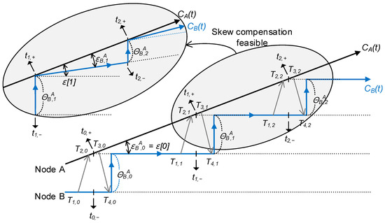
Figure 4.
Online clock skew estimation and compensation using two-way message exchange.
Upon completion of each timing message exchange, Node B computes the clock offset and subsequently updates its local clock by incorporating this offset into its current clock value. Due to the presence of clock skew, however, the divergence between the clocks of Nodes A and B increases monotonically until the next synchronization event occurs. Without skew compensation, maintaining tight synchronization would require frequent offset corrections that are accompanied by timing message exchanges, inevitably resulting in increased communication overhead. To mitigate this, it is desirable to process the observed offset sequence over time to extract and estimate the underlying clock skew dynamically. For this purpose, an RLS estimator is employed, which sequentially updates the skew estimate with each new offset observation, enabling efficient and timely skew compensation.
Initially, the relative clock skew can be computed or estimated only when Node B stores the offset-correction timestamps based on its local clock. Due to the clock adjustment that occurs during offset compensation, Node B’s clock experiences discontinuities, resulting in two distinct timestamp values for each synchronization event. Let us denote these as ti,− and ti,+ representing the local clock time immediately before and after the offset correction, respectively. These two values are related by
Subsequently, the relative clock skew over the interval between the i-th and (i + 1)-th message exchanges is computed. For convenience, the index i is set to start from zero. At the 0th message exchange, only offset compensation can be accomplished. After the 1st offset compensation with completed, the first value of clock skew can be estimated. The relative clock skew is given by
If Node B obtains , it can infer the operating frequency of Node A using the relationship:
Following this, Node B initiates skew compensation by modifying its clock frequency accordingly. A detailed explanation of the implementation aspects of this skew compensation approach is provided in Section 5.2.
Although the relative skew has been initially obtained, its reliability remains limited at present. This is because the numerator term in Equation (10) has the noise Xi+1 as in Equation (8), which introduces variability in the relative clock skew measurement. To reduce the estimation error between the calculated skew and its true value, a least squares estimation methodology is adopted. A new variable ε[i] is introduced, which differs from ; specifically, ε[i] quantifies the frequency offset with respect to Node B’s original clock frequency, whereas represents the offset relative to the compensated frequency after adjustments as can be seen in Figure 4. Both variables share the same starting value, i.e., . From the estimation perspective, the proposed update algorithms can be interpreted as a one-parameter least squares estimator over ε[i], assuming a linear model of offset growth between synchronization events.
Upon completion of the second offset correction, Node B obtains an updated estimate of the clock skew . Given that Node B has been applying skew compensation based on the initial estimate since the first message exchange, it can now infer the current operating frequency of Node A as well as the relative skew at this stage, which are expressed by
Using the two skew values, ε[0] and ε[1], Node B updates its least squares estimator for clock skew. The resulting estimator, denoted as , is defined by the following relation:
Accordingly, Node B applies skew compensation based on the updated estimate. With each offset correction event, Node B revises its skew estimate and modifies its clock frequency accordingly. It is important to note that Equation (14) represents a non-recursive estimator, which leads to increased data storage requirements as the index i grows. To address this, a recursive formulation of the least squares estimator is derived by expressing Equation (13) in the following generalized recursive form:
where the initial condition for and ε[i] are specified as follows.
Following the completion of the (i+1)-th offset correction, Node B obtains an updated skew estimator. Drawing from results detailed in Appendix A.1, this estimator can be expressed as
This expression indicates that updating the skew estimate requires three key inputs: (1) the previously computed skew , (2) the relative clock skew obtained at the (i + 1)-th synchronization iteration, and (3) the count of synchronization events i. Conventional clock skew compensation methods typically require storing multiple past samples to perform accurate skew estimation, with computations often deferred until sufficient data accumulates. In contrast, the proposed RLS-based estimator enables a node to iteratively update its skew estimate upon each timing exchange, facilitating online compensation while substantially reducing local memory demands. This attribute is particularly valuable for resource-constrained wireless and mobile network nodes.
4.2. Adaptive Clock Skew Estimation via Recursive Weighted Least Squares (RWLS)
In real-world scenarios, the interval between timing message exchanges for offset compensation may not be strictly periodic. Under conditions where exchange intervals remain constant, the variance of relative skew measurements remains uniform, enabling straightforward application of the RLS estimator. However, when timing intervals vary, these variances become unequal across observations. Notably, as shown in Equation (10), longer intervals between synchronization events correspond to reduced variance in skew estimates. The variance of the i-th relative skew estimate is quantified by
To handle varying levels of error in the measurements, the Recursive Weighted Least Squares (RWLS) method is employed instead of the standard RLS. Based on the results presented in Appendix A.2, the formulation of the skew estimator via RWLS is derived as
where the gain factor K[i] is computed by
The estimate variance of is recursively updated according to
Then, the recursion starts with the following initial values:
It is important to note that the initial variance value specified in Equation (22) is not precisely equal to one. Within the RWLS framework, the algorithm relies on the relative ratios of variances rather than their absolute magnitudes. Given that the variance of the clock skew estimate inversely scales with the square of the corresponding time interval, as shown in Equation (18), Node B needs only to store the initial measurement interval. Subsequent variance ratios are then calculated by comparing ongoing interval durations. Let us define TDi as the time difference between the i-th and (i + 1)-th message exchanges:
Then the normalized variance factor σi in Equation (20) is computed as
Using these quantities, and applying the initial values from Equation (22), Node B computes the initial gain K [1] according to Equation (20), derives the updated skew estimator from Equation (19), and updates the corresponding variance via Equation (21). This iterative process continues as more data become available, ensuring real-time estimator refinement. Compared to the purely periodic setting, the aperiodic estimation approach requires Node B to store only two additional parameters: the initial interval and the variance of the estimator from the previous update.
4.3. Noise-Augmented Formulation
This section extends the noise-augmented formulation by introducing a comprehensive model that accounts for various sources of imperfection in clock synchronization. While the previous sections presented idealized assumptions of perfect offset corrections and symmetric delays, practical systems are inevitably subject to non-idealities such as asymmetric communication delays, timestamping jitter, and residual errors from prior adjustments. To address these effects in a systematic way, we develop a refined formulation that makes such perturbations explicit and quantifies their impact on skew estimation.
Equation (10) offers an intuitive estimator for relative skew, but it assumes that offset evolves only due to frequency mismatch and that all previous corrections are ideal. In real deployments, however, measured offsets and intervals are inevitably corrupted by asymmetry, jitter, and residual errors. To explicitly capture these imperfections, let the true relative skew be ε*. Suppose the actual local elapsed time between the i-th and (i + 1)-th compensations is
Then, the corresponding ideal relative-offset increment over this interval is
In realistic conditions, the observed offset at round i as defined in Equation (8) can be represented as
where Xi captures intrinsic random fluctuations, ai denotes the path delay asymmetry, ji models timestamping jitter, and ui represents residual errors from imperfect offset correction. The observed increment across one interval then becomes
Similarly, the measured elapsed interval is perturbed as
where encompasses timing perturbations (for example, jitter in local timestamping or error in timing event uncertainty). For compactness, the aggregated perturbation term in the numerator can be defined as
where ηi collectively summarizes all deviations in the observed offset increment not explained by the true skew over the interval. Each term within ηi reflects, respectively, the change in random delay, change in delay asymmetry, change in timestamping jitter, and the residual correction error during the interval.
The per-interval skew estimator then becomes
Assuming that the denominator perturbation is small relative to the elapsed interval (), a first-order Taylor expansion gives
Based on this approximation, the bias and variance of the estimator can be expressed as
These expressions clarify the distinct statistical roles of different perturbations. Zero-mean jitter and intrinsic fluctuations inflate the variance but do not bias the estimate; evolving asymmetry and non-zero residuals produce systematic bias; denominator noise contributes an additional variance term that scales with . If numerator and denominator perturbations are uncorrelated, i.e., , the variance reduces to the sum of two additive components inversely proportion to . This demonstrates that the estimator’s reliability improves with longer compensation intervals, since the effective noise power decreases quadratically with interval length.
Overall, this formulation complements the earlier sections by formalizing the intuition behind Equation (10) and providing a rigorous explanation for the variance scaling observed in Section 4.2. It bridges the lightweight recursive structure with a clear statistical interpretation: bias emerges only under evolving or non-zero-mean perturbations, while variance universally decays as . This not only strengthens the justification for weighted updates in the RWLS framework but also highlights the conditions under which the skew estimator remains unbiased and efficient.
5. Implementation Considerations
5.1. Exclude Outliers
The proposed clock skew estimators are updated each time a new clock offset is acquired via timing message exchanges. Nevertheless, occasionally the newly obtained offset may exhibit anomalous behavior due to factors such as node resets or changes in the reference node. In such instances, while the anomalous offset is still used for offset compensation, it is desirable to exclude it from the skew estimation process.
Letting ρ represent the maximum allowable drift rate of the crystal oscillator relative to an ideal clock, as typically specified in the respective datasheets, the relative drift between two distinct oscillators can be bounded within ±2ρ. Accordingly, any offset value violating the condition in Equation (35) is regarded as an outlier and is thus rejected from the skew estimation.
Although offset calculation inherently involves nondeterministic factors, their influence on outlier rejection is minimal and therefore disregarded for simplicity. A related study that leverages such bounded drift assumptions to establish deterministic guarantees in synchronization accuracy is presented in [31].
Nevertheless, while this study employs a fixed threshold for outlier rejection, adaptive threshold mechanisms that adapt to environments with time-varying noise or measurement uncertainty could further enhance robustness. Exploration of such methods represents a promising direction for future work.
5.2. Implementation of Skew Compensation
Using the estimated clock skew , any node (Node B) can infer the operating frequency of the reference node (Node A) as described by:
To perform skew compensation, Node B should adjust its own clock frequency. A simple practical approach for frequency adjustment leverages a software-based timer, which can be modeled as a linear function:
where the first-order coefficient (α) is determined by the estimated skew. In practice, periodic offset compensation is employed to facilitate frequency adaptation. For example, if the estimated skew is 0.001, then after every 1000 clock counts, Node B incrementally advances its local clock by one count, effectively increasing its operational frequency. Conversely, with an estimated skew of −0.001, the node decrements its count by one every 1000 cycles, thereby lowering its clock rate. To implement this adjustment, the Timer Compare Register (TCPR) functionality available in microcontrollers is utilized. In compare mode, an interrupt is generated whenever the timer value matches the designated compare register value.
Figure 5 schematically depicts the process of skew compensation (frequency adjustment). Upon estimating the skew through the (i + 1)-th timing message exchange, Node B computes a skew compensation interval, τi, as described in
Subsequently, Node B schedules its next synchronization event at its local time (ti+1,+ + τi). When this scheduled time is reached, an interrupt (or equivalent event) triggers the skew correction logic. At each synchronization event, Node B dynamically recalculates the next adjustment time (CB(t)+ τi) for skew compensation based on its current clock count CB(t), and then updates its clock count as required: incrementing by one if the estimated skew is positive, and decrementing by one otherwise.
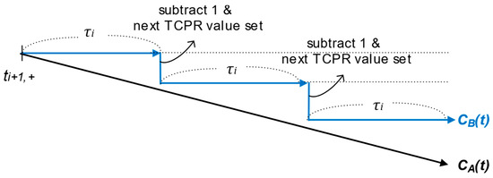
Figure 5.
Process of skew compensation in case of negative .
The detailed implementation of the proposed skew compensation algorithm based on RWLS is summarized in Algorithm 1, which presents the corresponding pseudo code. In this algorithm, some computational steps are aligned with specific equations from the theoretical framework, explicitly indicating how the recursive updates of the skew estimator, gain factor, and variance are performed in practice. The pseudo code also includes procedures for outlier detection, skew compensation interval scheduling, and integration with timer interrupt mechanisms, making it a comprehensive guide for practical deployment of the algorithm. To further enhance clarity and facilitate understanding of the proposed framework discussed thus far, a glossary of essential terms and symbols is provided in Table 1.
| Algorithm 1. Pseudo code for time synchronization using RWLS | |
| Step | Pseudo Code |
| 1 | Begin |
| 2 | Initialize all variables |
| 3 | while (true) do |
| 4 | if (timing information is obtained) then |
| 5 | Perform offset(θi) correction |
| 6 | i ← i + 1 |
| 7 | if (i = 1) then |
| 8 | Store TD0 using Equation (23) |
| 9 | goto Step 3 |
| 10 | else |
| // Clock skew estimation | |
| 11 | Obtain εi using Equation (10) |
| 12 | Calculate σi using Equation (24) |
| 13 | Update K[i] using Equation (20) |
| 14 | Update using Equation (19) |
| 15 | Update using Equation (21) |
| 16 | Calculate τi using Equation (38) |
| 17 | if (εi is outlier according to Equation (35)) then |
| 18 | Discard measurement and goto Step 2 |
| 19 | else |
| // Clock skew compensation | |
| 20 | Set Timer Compare Register: TCPR ← Tcurrent + τi |
| 21 | end if |
| 22 | end if |
| 23 | end if |
| 24 | if (timer compare interrupt occurs) then |
| 25 | execute TimerCompareISR() |
| 26 | end if |
| 27 | end while |
| 28 | procedure TimerCompareISR() |
| 29 | if ( > 0) then |
| 30 | Tcurrent++ |
| 31 | else if ( < 0 then |
| 32 | Tcurrent-- |
| 33 | end if |
| 34 | TCPR ← TCPR + τi |
| 35 | end procedure |
6. Performance Analysis
6.1. Simulation Results
The performance of the proposed online clock skew estimators was evaluated through Monte Carlo simulations. Figure 6 presents the evolution of the mean square error (MSE) of the proposed clock skew estimator with respect to the number of clock samples under various observation noise variances (σ2). The MSE consistently decreases as more clock samples become available, demonstrating the estimator’s convergence and the improvement in estimation accuracy with additional timing information.
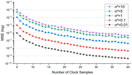
Figure 6.
MSE vs. number of clock samples for different noise variances.
For all tested noise variances, the reduction in error is most rapid during the initial accumulation of samples, after which each curve approaches a steady-state value. It is natural that the steady-state MSE is directly influenced by the noise variance: higher observation noise results in higher residual error even after many samples, while lower noise allows for more accurate estimation. These results confirm that both RLS and RWLS estimators reliably improve with additional samples and quantifies the impact of noise on synchronization accuracy.
To evaluate the clock skew estimation performance, a comparative analysis was conducted among several established methods: the single-step skew estimator, batch least squares regression, the Kalman filter, the MLE, and the proposed online RLS and RWLS estimators. The simulations assumed oscillators with ±20 PPM frequency variation, and Gaussian noise with variance 1 was used to model errors in offset correction. The single-step estimator calculates skew by comparing consecutive offsets, applying the estimate only to the next interval. Batch least squares regression fits a line through multiple offset observations, widely used in protocols such as RBS and FTSP, where convergence depends on data volume and synchronization interval. The Kalman filter is known for its minimized skew error but entails higher computational complexity. The MLE method provides high estimation accuracy, but its convergence rate varies depending on the optimization algorithm employed.
Figure 7 compares the absolute skew estimation error, presented as averages with standard deviations in parts per billion (PPB), across these methods as a function of the number of samples. The proposed RLS and RWLS estimators significantly reduce estimation errors relative to the single-step method and perform comparably to batch least squares. The Kalman filter and MLE provide the lowest errors overall, with MLE demonstrating slightly better accuracy as the number of samples increases. Despite their superior precision, Kalman filter and MLE approaches bear practical limitations owing to computational demands and sensitivity to network conditions such as packet loss. In contrast, the RLS and RWLS methods offer an effective trade-off between accuracy and efficiency, making them well-suited for real-time skew estimation in resource-constrained wireless systems.
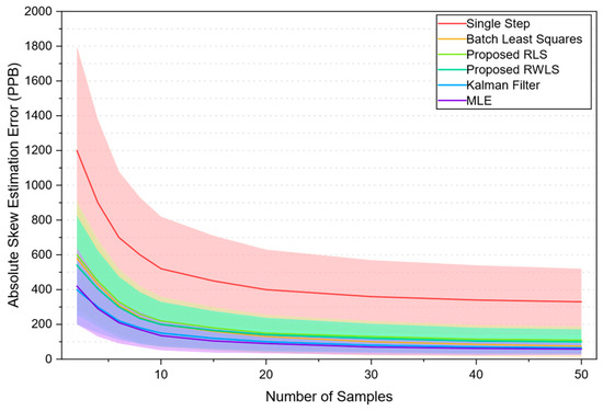
Figure 7.
Comparison of clock skew estimation error across different estimator types. Shaded regions around each main curve indicate mean ± standard deviation.
In mobile networks where nodes operate under strict resource constraints, computational complexity in clock skew estimation is critical. Table 2 summarizes the per-update time and space complexities of five representative estimators using Big-O notation. The single-step estimator requires constant time and memory, O(1). Batch least squares scales linearly with the window size N, yielding O(N) time and memory complexity. RLS and RWLS generally incur O(p2) cost per update, but in the proposed framework where only skew is estimated (p = 1), the complexity reduces to O(1). In contrast, the Kalman filter requires O(m3) time and O(m2) memory due to matrix inversion, with m = 2 when both offset and skew are estimated [24,32]. As noted in [29], both the computational and memory complexity of the MLE scale approximately linearly with the number of samples N stored in the buffer, yielding O(N) for time and space. These results demonstrate that the proposed RLS and RWLS achieve complexity comparable to the single-step method, while offering improved accuracy.

Table 2.
Comparison of complexity across different estimator types.
6.2. Experimental Results
To validate the proposed skew compensation algorithms, various time synchronization protocols were implemented and tested on a Zigbee-based node platform, selected for its efficient system architecture and minimal resource requirements. The platform runs a lightweight operating system with a network protocol stack. The nodes utilize a 32.768 kHz software timer, which is derived from a crystal oscillator with a frequency tolerance of ±20 PPM. Consequently, the maximum time difference between two distinct oscillators can accumulate up to 2.4 ms over a one-minute interval. A series of measurements was conducted within an indoor testbed environment. One node served as the reference node, while another node acted as the sink node, connected to a PC via a serial port to collect synchronization error data from the other nodes. The synchronization discrepancies observed between the reference node and the other nodes were systematically evaluated under two different network topologies as shown in Figure 8: single-hop and multi-hop.
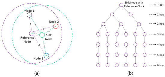
Figure 8.
Network topology configuration for experiments: (a) Single-hop network topology, where the numbers ‘1’ and ‘2’ above the links represent the order of message broadcasts for R-R synchronization; (b) Multi-hop tree-based network topology with up to six hops.
6.2.1. Single-Hop Network Topology
Synchronization errors were evaluated in a single-hop network consisting of five nodes to verify the functionality of the proposed estimator, as shown in Figure 8a. The R-R synchronization scheme based on the RBS protocol was adopted for offset compensation. The sink node acted as the beacon transmitter, periodically sending wireless beacon signals to all other nodes within the network, including the reference node. Upon reception of each beacon message, the reference node immediately transmitted its local timestamp to all other nodes, facilitating their synchronization process. Each node generated a short pulse at a specific output port every four seconds, triggered by the overflow interrupt of its local clock. A digital oscilloscope was used to accurately measure the time difference between the pulses of the reference node and those of the other nodes. These values are plotted in Figure 9, where for simplicity, the offset of Node i with respect to the reference node is denoted θi.
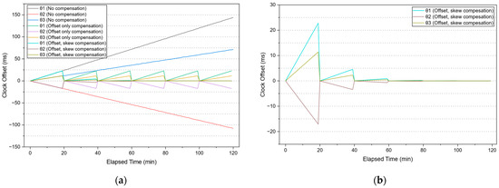
Figure 9.
Clock offset variation in three nodes relative to the reference node over elapsed time: (a) Clock offset measurements under three scenarios: “No compensation,” “Offset only compensation,” and “Offset, skew compensation”. (b) Detailed view of the “Offset, skew compensation” scenario with enhanced y-axis resolution.
First, to investigate the effect of clock skew, clock offsets were initially synchronized and then left unsynchronized for 120 min. As expected, due to frequency drift, the offsets corresponding to the “No compensation” scenario in Figure 9a gradually diverged over time. In the second scenario, offset compensation was performed every 20 min by exchanging timestamp messages among the nodes, allowing three nodes to periodically realign their clocks with the reference node. Although this improved synchronization temporarily, the clocks began to drift apart again due to residual clock skew as shown by the “Offset only compensation” plot in Figure 9a. Finally, in the third scenario, skew estimation and compensation were additionally applied using the proposed online RLS algorithm. Skew correction commenced after two clock offset samples were obtained (after 10 min), and estimation accuracy improved as more samples became available. The results for this “Offset, skew compensation” scenario are shown in Figure 9a; for clarity, the same plot is also shown in Figure 9b with an expanded y-axis, clearly illustrating that offset errors were maintained below 1 ms after three rounds of compensation.
6.2.2. Multi-Hop Tree-Based Network Topology
To evaluate the performance of the proposed skew estimators further, a tree-based multi-hop topology of up to six hops with 30 mobile nodes, as shown in Figure 8b, was constructed. Each node was programmed to report its clock offset (θi) to the sink node at every offset compensation event. This clock offset represents the instantaneous time difference between the node’s local clock and that of the reference node, measured just prior to compensation. Although this value may include potential measurement uncertainties and therefore may not be exact, it serves as a close approximation of the time synchronization error at that moment. The synchronization error was computed as the average of the absolute values of these reported offsets across nodes of the same hop count.
Offset compensation was performed using the S-R synchronization scheme of TPSN. The sink node managed the initiation and interval of synchronization, triggering the two-way exchanges that cascade throughout the network via the links of the tree. Since a tree topology is assumed, each node synchronizes only with its parent node. If a mesh topology is adopted, it can potentially provide higher synchronization accuracy by enabling synchronization with neighboring nodes in addition to the parent.
To analyze the impact of clock skew with respect to hop count, experiments were first performed applying only offset compensation, as in standard TPSN. Each node executed offset compensation at intervals of 30 min or 1 h. The synchronization error data collected from all nodes were averaged based on their hop count relative to the sink node. As shown in Figure 10a, the average synchronization error in the “Offset only compensation” case tends to increase slightly with hop count, and the influence of clock skew on synchronization error becomes more pronounced as the interval between compensations increases.
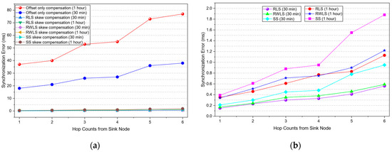
Figure 10.
Synchronization performance across hop counts from the sink node: (a) Synchronization error for both “offset compensation only” and “combined offset and skew compensation using RLS, RWLS, and single-step estimators”. (b) Detailed view of the offset and skew compensation results with a modified y-axis scale for enhanced visibility.
In a subsequent set of experiments, skew compensation was incorporated alongside offset compensation to evaluate its improvement. The proposed online RLS and RWLS estimators were compared with the single-step skew estimator. As shown in Figure 10a, synchronization error incorporating both offset and skew compensation is presented alongside the offset only compensation results. Figure 10b provides a detailed view of the offset and skew compensation scenario, illustrating the synchronization error according to hop count measured at 30 min and 1 h after the last compensation event.
The results clearly demonstrate the effectiveness of the proposed RLS and RWLS estimators for skew estimation. The synchronization error can be maintained below 1 ms for nodes within five hops at a synchronization interval of one hour. However, even after skew estimation has converged, synchronization error exhibits a linear increase over time due to residual estimation inaccuracies. Furthermore, as the hop count increases, various uncertainties accumulate, resulting in a reduction in skew estimation accuracy and, consequently, higher synchronization errors. This suggests that nodes farther from the reference node require more frequent synchronization message exchanges to maintain an acceptable level of timing accuracy, compared to those closer to the reference.
To mitigate error accumulation with increasing hop count, conventional distributed methods such as Average Time Synchronization (ATS) [33] have been proposed. More recent approaches use virtual-link based consensus schemes that enable clock information exchange beyond immediate neighbors, thereby improving offset averaging and reducing error propagation [34]. Although integrating these techniques into multi-hop ITS networks could complement the proposed method and is considered promising for future work, their practical effectiveness and integration have not yet been validated in this study, thus representing an important limitation to be addressed in subsequent research.
7. Conclusions
This paper proposes low-overhead online clock skew estimation and compensation algorithms suitable for resource-constrained wireless mobile networks and ITS environments. Through both simulation and experimental validation, the proposed RLS and RWLS estimators are shown to efficiently reduce skew-induced timing errors and maintain high synchronization accuracy across a range of operational scenarios.
A key advantage of the proposed methods is their applicability across V2V, V2I, and I2I communication scenarios, providing a cost-effective means to enhance time synchronization without the need for additional hardware. The approach is readily implementable within contemporary protocol architectures and is particularly well-suited for mobile and vehicular networks where GNSS availability may be intermittent. By substantially reducing skew-induced errors, the proposed approach can enhance the robustness and precision of timing in both vehicular and infrastructure networks. Future work will focus on optimizing the approach under dynamic network conditions, integrating it with emerging ITS standards, and exploring distributed synchronization techniques to further reduce multi-hop error accumulation.
Funding
This research received no external funding.
Institutional Review Board Statement
Not applicable.
Data Availability Statement
The data presented in this study are available on request from the corresponding author due to privacy and planned follow-up research. Access may be granted upon reasonable request, subject to a data use agreement and institutional approval.
Conflicts of Interest
The author declares no conflicts of interest. The funders had no role in the design of the study; in the collection, analyses, or interpretation of data; in the writing of the manuscript; or in the decision to publish the results.
Abbreviations
The following abbreviations are used in this manuscript:
| ITS | Intelligent Transportation Systems |
| V2V | Vehicle-to-Vehicle |
| V2I | Vehicle-to-Infrastructure |
| I2I | Infrastructure-to-Infrastructure |
| OBE | On-Board Equipment |
| RSU | Roadside unit |
| GNSS | Global Navigation Satellite System |
| GPS | Global Positioning System |
| OTA | Over-The-Air |
| VANET | Vehicular Ad Hoc Network |
| WSN | Wireless Sensor Network |
| S-R | Sender-Receiver |
| R-R | Receiver-Receiver |
| TPSN | Timing-sync Protocol for Sensor Networks |
| RBS | Reference Broadcast Synchronization |
| RLS | Recursive Least Squares |
| RWLS | Recursive Weighted Least Squares |
| PPM | Parts Per Million |
| TCPR | Timer Compare Register |
| MLE | Maximum Likelihood Estimator |
| PPB | Parts Per Billion |
Appendix A
Appendix A.1. RLS Estimator [35]
Consider a set of observations x[n] with indices n = 0, 1,…, N−1. When a new data point x[N] becomes available, the least squares estimate of the parameter is calculated as the average over all N + 1 samples:
While this approach provides the exact estimator, computing this sum at each step is computationally inefficient, especially for real-time applications. To enable efficient online updating, the recursive form of the estimator is used as
Appendix A.2. RWLS Estimator [35]
When the noise variance varies across measurements, a weighted least squares estimation is preferable. The RWLS estimator extends the RLS model by assigning weights inversely proportional to the error variance of each sample. The RWLS estimator updates the parameter estimate as
where K[N] is the adaptive gain factor defined by
The variance of the estimator is also recursively updated by
References
- Hasan, K.F.; Wang, C.; Feng, Y.; Tian, Y.-C. Time synchronization in vehicular ad-hoc networks: A survey on theory and practice. Veh. Commun. 2018, 14, 39–51. [Google Scholar] [CrossRef]
- Ahmed, E.; Gharavi, H. Cooperative vehicular networking: A survey. IEEE Trans. Intell. Transp. Syst. 2018, 19, 996–1014. [Google Scholar] [CrossRef] [PubMed]
- Hasan, K.F.; Feng, Y.; Tian, Y.-C. Precise GNSS time synchronization with experimental validation in vehicular networks. IEEE Trans. Netw. Serv. Manag. 2023, 20, 3289–3301. [Google Scholar] [CrossRef]
- Garcia, M.H.C.; Hélou, A.E.; Ceron, R.V.; Vieira, L.F.M.; Vieira, M.A.M. A Tutorial on 5G NR V2X Communications. IEEE Commun. Surv. Tut. 2021, 23, 1972–2026. [Google Scholar] [CrossRef]
- Clancy, J.; Khan, A.N.; Shafi, F.; Azam, M.A.; Rehman, S.U.; Al-Turjman, F. Wireless Access for V2X Communications: Research, Challenges and Opportunities. IEEE Commun. Surv. Tut. 2024, 26, 2082–2119. [Google Scholar] [CrossRef]
- Zhang, T.; Wang, G.; Xue, C.; Wang, J.; Nixon, M.; Han, S. Time-sensitive networking (TSN) for industrial automation: Current advances and future directions. ACM Comput. Surv. 2025, 57, 30. [Google Scholar] [CrossRef]
- Zhu, L.; Zhang, H.; Li, X.; Zhu, F.; Liu, Y. GNSS Timing Performance Assessment and Results Analysis. Sensors 2022, 22, 2486. [Google Scholar] [CrossRef]
- Hasan, K.F.; Feng, Y.; Tian, Y.-C. GNSS Time Synchronization in Vehicular Ad-Hoc Networks: Benefits and Feasibility. IEEE Trans. Intell. Transp. Syst. 2018, 19, 3915–3924. [Google Scholar] [CrossRef]
- Weng, Y.; Zhang, Y. A Survey of Secure Time Synchronization. Appl. Sci. 2023, 13, 3923. [Google Scholar] [CrossRef]
- Balakrishnan, K.; Dhanalakshmi, R.; Sinha, B.B.; Gopalakrishnan, R. Clock synchronization in industrial Internet of Things and potential works in precision time protocol: Review, challenges and future directions. Int. J. Cogn. Comput. Eng. 2023, 4, 205–219. [Google Scholar] [CrossRef]
- Liu, J.; Deng, Z.; Hu, E.; Huang, Y.; Deng, X.; Zhang, Z.; Ding, Z.; Liu, B. GNSS-5G Hybrid Positioning Based on Joint Estimation of Multiple Signals in a Highly Dependable Spatio-Temporal Network. Remote Sens. 2023, 15, 4220. [Google Scholar] [CrossRef]
- Camajori Tedeschini, B.; Brambilla, M.; Italiano, L.; Reggiani, S.; Vaccarono, D.; Alghisi, M.; Benvenuto, L.; Goia, A.; Realini, E.; Grec, F.; et al. A Feasibility Study of 5G Positioning with Current Cellular Network Deployment. Sci. Rep. 2023, 13, 15281. [Google Scholar] [CrossRef] [PubMed]
- Gu, S.; Mao, F.; Gong, X.; Wang, L.; Zhou, Y. Improved Short-Term Stability for Real-Time GNSS Satellite Clock Estimation with Clock Model. J. Geod. 2023, 97, 61. [Google Scholar] [CrossRef]
- Kim, H.-I.; Park, K.-D. Satellite Positioning Accuracy Improvement in Urban Canyons Through a New Weight Model Utilizing GPS Signal Strength Variability. Sensors 2025, 25, 4678. [Google Scholar] [CrossRef]
- Dang, F.; Sun, X.K.; Liu, K.B.; Li, Y. A Survey on Clock Synchronization in the Industrial Internet. J. Comput. Sci. Technol. 2023, 38, 146–165. [Google Scholar] [CrossRef]
- Association of Radio Industries and Businesses (ARIB). 700 MHz Band Intelligent Transport Systems; ARIB STD-T109, Ver. 1.3 (English Translation); ARIB: Tokyo, Japan, 2017; Available online: https://www.arib.or.jp/english/html/overview/doc/5-STD-T109v1_3-E1.pdf (accessed on 15 August 2025).
- BK, S.; Azam, F. Ensuring Security and Privacy in VANET: A Comprehensive Survey of Authentication Approaches. J. Comput. Netw. Commun. 2024, 2024, 1818079. [Google Scholar] [CrossRef]
- Abbasi, M.; Shahraki, A.; Barzegar, H.R.; Pahl, C. Synchronization Techniques in Device-to-Device and Vehicle-to-Vehicle-Enabled Cellular Networks: A Survey. Comput. Electr. Eng. 2021, 90, 106955. [Google Scholar] [CrossRef]
- Bai, K.; Wu, J.; Wu, H. High-precision time synchronization algorithm for unmanned aerial vehicle ad hoc networks based on bidirectional pseudo-range measurements. Ad. Hoc. Netw. 2024, 152, 103326. [Google Scholar] [CrossRef]
- Ganeriwal, S.; Kumar, R.; Srivastava, M.B. Timing-sync protocol for sensor networks (TPSN). In Proceedings of the 1st International Conference on Embedded Networked Sensor Systems (SenSys ’03), Los Angeles, CA, USA, 5–7 November 2003; pp. 138–149. [Google Scholar] [CrossRef]
- Elson, J.; Girod, L.; Estrin, D. Fine-grained network time synchronization using reference broadcasts. In Proceedings of the 5th Symposium on Operating Systems Design and Implementation (OSDI 2002), Boston, MA, USA, 9–11 December 2002; pp. 147–163. [Google Scholar] [CrossRef]
- Maróti, M.; Kusy, B.; Simon, G.; Lédeczi, Á. The flooding time synchronization protocol. In Proceedings of the 2nd International Conference on Embedded Networked Sensor Systems (SenSys ’04), Baltimore, MD, USA, 3–5 November 2004; pp. 39–49. [Google Scholar] [CrossRef]
- Wu, Y.-C.; Chaudhari, Q.M.; Serpedin, E. Clock synchronization of wireless sensor networks. IEEE Signal Process. Mag. 2011, 28, 124–138. [Google Scholar] [CrossRef]
- Hamilton, B.R.; Ma, X.; Zhao, Q.; Xu, J. ACES: Adaptive clock estimation and synchronization using Kalman filtering. In Proceedings of the 14th ACM International Conference on Mobile Computing and Networking (MobiCom ’08), San Francisco, CA, USA, 14–19 September 2008; pp. 152–162. [Google Scholar] [CrossRef]
- Jin, M.; Xing, T.; Chen, X.; Meng, X.; Fang, D.; He, Y. DualSync: Taming clock skew variation for synchronization in low-power wireless networks. In Proceedings of the 35th Annual IEEE International Conference on Computer Communications (IEEE INFOCOM 2016), San Francisco, CA, USA, 10–15 April 2016; pp. 1–9. [Google Scholar] [CrossRef]
- Noh, K.-L.; Chaudhari, Q.M.; Serpedin, E.; Suter, B.W. Novel clock phase offset and skew estimation using two-way timing message exchanges for wireless sensor networks. IEEE Trans. Commun. 2007, 55, 766–777. [Google Scholar] [CrossRef]
- Lenzen, C.; Sommer, P.; Wattenhofer, R. PulseSync: An Efficient and Scalable Clock Synchronization Protocol. IEEE/ACM Trans. Netw. 2015, 23, 717–727. [Google Scholar] [CrossRef]
- Sichitiu, M.L.; Veerarittiphan, C. Simple, accurate time synchronization for wireless sensor networks. In Proceedings of the IEEE Wireless Communications and Networking Conference (WCNC 2003), New Orleans, LA, USA, 16–20 March 2003; Volume 2, pp. 1266–1273. [Google Scholar] [CrossRef]
- Shi, F.; Li, H.; Yang, S.X.; Tuo, X.; Lin, M. Novel maximum likelihood estimation of clock skew in one-way broadcast time synchronization. IEEE Trans. Ind. Electron. 2020, 67, 9948–9957. [Google Scholar] [CrossRef]
- Chaloupka, Z.; Alsindi, N.; Aweya, J. Clock skew estimation using Kalman filter and IEEE 1588v2 PTP for telecom networks. IEEE Commun. Lett. 2015, 19, 1181–1184. [Google Scholar] [CrossRef]
- Sugihara, R.; Gupta, R.K. Clock Synchronization with Deterministic Accuracy Guarantee. In Proceedings of the 8th European Conference on Wireless Sensor Networks (EWSN 2011), Bonn, Germany, 14–16 February 2011; Marrón, P.J., Whitehouse, K., Eds.; Lecture Notes in Computer Science; Springer: Berlin/Heidelberg, Germany, 2011; Volume 6567, pp. 130–146. [Google Scholar] [CrossRef]
- Raitoharju, M.; Piché, R. On Computational Complexity Reduction Methods for Kalman Filter Extensions. IEEE Aerosp. Electron. Syst. Mag. 2019, 34, 2–19. [Google Scholar] [CrossRef]
- Schenato, L.; Fiorentin, F. Average TimeSync: A Consensus-Based Protocol for Time Synchronization in Wireless Sensor Networks. IFAC Proc. Vol. 2009, 42, 30–35. [Google Scholar] [CrossRef]
- Wang, H.; Zou, Y.; Liu, X.; Meng, Z. A Rapid Time Synchronization Scheme Using Virtual Links and Maximum Consensus for Wireless Sensor Networks. IEEE Internet Things J. 2025, 12, 3318–3329. [Google Scholar] [CrossRef]
- Kay, S.M. Fundamentals of Statistical Signal Processing, Volume I: Estimation Theory; Prentice Hall: Englewood Cliffs, NJ, USA, 1993; ISBN 978-0-13-345711-7. [Google Scholar]
Disclaimer/Publisher’s Note: The statements, opinions and data contained in all publications are solely those of the individual author(s) and contributor(s) and not of MDPI and/or the editor(s). MDPI and/or the editor(s) disclaim responsibility for any injury to people or property resulting from any ideas, methods, instructions or products referred to in the content. |
© 2025 by the author. Licensee MDPI, Basel, Switzerland. This article is an open access article distributed under the terms and conditions of the Creative Commons Attribution (CC BY) license (https://creativecommons.org/licenses/by/4.0/).