Article

Effect of Oxygen Concentration on the Corrosion Behaviour of Coated and Uncoated 316L Stainless Steel in Liquid Lead

by
Daniel Petrescu
1,2,
Florentina Golgovici
2,*,
Mircea Corban
3,
Oana Brincoveanu
4 and
Ioana Demetrescu
2,5,*
1
Institute for Nuclear Research Pitesti, POB 78, Campului Street, No. 1, 115400 Mioveni, Romania
2
Department of General Chemistry, Faculty of Chemical Engineering and Biotechnologies, National University of Science and Technology Politehnica Bucharest, Splaiul Independentei Street, No. 313, 060042 Bucharest, Romania
3
National R&D Institute for Nonferrous and Rare Metals-IMNR, 077145 Pantelimon, Romania
4
National Institute for Research and Development in Microtechnologies, IMT-Bucharest, Erou Iancu Nicolae Str., 077190 Bucharest, Romania
5
Academy of Romanian Scientists, 3 Ilfov, 050094 Bucharest, Romania
*
Authors to whom correspondence should be addressed.
Appl. Sci. 2025, 15(19), 10572; https://doi.org/10.3390/app151910572
Submission received: 4 September 2025 / Revised: 22 September 2025 / Accepted: 24 September 2025 / Published: 30 September 2025

Abstract

Featured Application

The paper is dedicated to the investigation of the effect of dissolved oxygen on the corrosion resistance of EB-PVD coated and uncoated austenitic 316L stainless steel immersed in liquid lead at 550 °C.

Abstract

The 316L stainless steel, uncoated and coated with two types of EB-PVD thin-film deposits, was tested in liquid lead both under oxygen-saturated conditions (~10−3 wt.%) for exposure times of 1000 and 2000 h and under low-oxygen conditions (~108 wt.%) for 1000 h. The first coating consisted of a ~1 µm NiCrAlY thin film. At the same time, the second was a NiCrAlY/Al2O3 multilayer with a total thickness of ~3 µm, on top of which an additional 100–200 nm metallic Cr layer was deposited. Uncoated specimens tested under oxygen-saturated conditions developed a duplex oxide layer on their surface. SEM-EDS analyses revealed that the inner layer was denser and contained Fe, Cr, and O, whereas the outer layer was more porous and composed mainly of Fe and O. Microscopic examinations indicated that the multilayer-coated specimens exposed to low-oxygen conditions exhibited no signs of material degradation. In contrast, both the uncoated samples and those coated only with a single NiCrAlY layer showed generalised corrosion over the entire surface after exposure to liquid lead at low oxygen concentrations. The austenitic microstructure was degraded to a depth of 100–200 µm. Vickers microhardness indentations performed on the structurally altered regions revealed two distinct corrosion zones with markedly different hardness values.

1. Introduction

Generation IV nuclear reactors constitute a diverse class of advanced nuclear systems characterised by enhanced safety features, improved thermal efficiencies, and the capability to recycle spent nuclear fuel, thereby reducing long-term radioactive waste [1,2,3,4]. Some of the system reactors of Generation IV include the supercritical water-cooled reactor (SCWR) [5], the Molten Salt Reactor (MSR) [6], the Gas-Cooled Fast Reactor System (GFR) [7], and the Sodium-Cooled Fast Reactor System (SFR) [8]; they have attracted increasing attention, making them the subjects of theoretical and experimental research [9,10]. Among these systems, the lead-cooled fast reactor (LFR) has attracted significant attention due to its use of lead or lead–bismuth eutectic (LBE) as a high-temperature coolant [11]. Lead offers excellent thermophysical properties, including a high boiling point, high thermal conductivity, and chemical stability, making it an efficient heat transfer fluid. In addition, its high atomic number provides effective gamma shielding, enhancing reactor safety by serving as an inherent radiological barrier. Furthermore, the large thermal expansion coefficient of molten lead facilitates natural circulation, thus contributing to passive safety and reducing reliance on active pumping systems [12]. These characteristics position LFRs as a promising candidate within the Generation IV framework, with potential to deliver both sustainable energy generation and improved nuclear waste management.
One of the principal challenges in the development of Gen-IV lead-cooled fast reactors (LFRs) is the chemical interaction between heavy liquid–metal coolants and structural/cladding steels, which can suffer from dissolution, oxidation, and liquid–metal-assisted degradation under representative temperatures and flow conditions [13,14,15,16,17].
Active oxygen control in heavy liquid metal (HLM) systems is employed to promote the formation of a protective oxide layer on steel surfaces by dissolving precise amounts of oxygen into the coolant [18,19,20]. According to Ellingham’s diagram, the oxygen concentration in liquid lead should be chosen to ensure that magnetite can be generated on the surface of the iron-based structural material, as well as to ensure that PbO is not generated, which depends on the specific operation temperature but is generally controlled at 10−8–10−6 wt.% [21,22,23]. The optimal oxygen concentration range is determined by the balance between the solubility of oxygen in the HLM (Pb or LBE), which defines the upper limit, the stability of protective iron oxides (Fe3O4/spinel), which defines the lower limit, and the operating temperature. However, these solubilities are slightly different in Pb compared to LBE, and the admissible oxygen window for LBE is narrower at reactor operating temperatures typically in the range of 10−7–10−6 wt.% O [13].
It is widely recognised that self-passivation, achieved through controlled oxygen injection into the liquid lead coolant, provides effective corrosion protection for steel at operating temperatures below 500 °C [24,25,26]. However, at temperatures exceeding 500 °C, the protective oxide film tends to become unstable, leading to accelerated dissolution. Under such conditions, additional protective strategies are required to ensure the long-term integrity of structural materials in liquid lead environments [27].
Austenitic stainless steels, particularly 316L, have long been considered as candidate structural materials for advanced nuclear reactor systems due to their widespread industrial use, weldability, and good mechanical properties at elevated temperatures. In the context of Generation IV lead-cooled fast reactors (LFRs), 316L stainless steel has been investigated for applications such as reactor internals, heat exchanger components, and piping exposed to circulating liquid lead or lead–bismuth eutectic (LBE) [13,28]. However, the corrosion performance of 316L in heavy liquid metal environments presents significant challenges. At operating temperatures above 450–500 °C, selective dissolution of nickel and chromium into the molten lead can occur, leading to matrix depletion, loss of passivity, and microstructural destabilisation.
Experimental studies in static have confirmed that corrosion rates of 316L increase with temperature and flow velocity, with severe degradation observed beyond 550 °C in oxygen-lean conditions [13]. For this reason, the material is generally considered unsuitable for direct exposure to high-temperature liquid lead coolants unless protective measures are employed. Surface engineering approaches, including alumina coating, FeCrAl overlays, and pre-oxidation treatments, have been proposed to extend the serviceability of 316L in LFR-relevant conditions [13,29].
This study addresses the corrosion behaviour of austenitic 316L stainless steel in liquid lead at 550 °C, with a particular emphasis on the influence of dissolved oxygen—a critical parameter for structural material qualification in Generation IV lead-cooled fast reactors. While the role of oxygen in stabilising protective oxides has been widely recognised, systematic investigations of its effect on 316L stainless steel under both oxygen-saturated (~10−3 wt.%) and low-oxygen (~10−8 wt.%) conditions remain limited. The novelty of this work lies in the comparative assessment of uncoated and EB-PVD-coated 316L specimens, employing advanced thin-film architectures to improve corrosion resistance in oxygen-deficient lead environments. Two innovative coating systems were examined: a ~1 µm NiCrAlY thin film and a NiCrAlY/Al2O3 multilayer (~3 µm) modified with a nanoscale Cr surface layer (100–200 nm). By combining extended exposures (1000–2000 h) with multi-scale characterisation techniques (SEM-EDS and microhardness), the study provides new insights into the protective role of engineered surfaces and the degradation pathways of 316L stainless steel in lead. The experimental design offers a novel framework for assessing coating effectiveness under controlled oxygen potentials, contributing to the ongoing effort to qualify structural materials for long-term operation in heavy liquid metal-cooled reactors.

2. Materials and Methods

For the corrosion tests, specimens with different geometries were prepared from a commercial AISI 316L stainless steel plate produced by Outokumpu Stainless Oy (Helsinki, Finland). The uncoated samples tested in liquid lead had a rectangular shape with dimensions of 25 mm × 12 mm × 3 mm and a 4 mm hole. For the coated samples, more complex specimens were used, with a length of 40 mm, a width of 11 mm, and a central section narrowed to 3 mm over a length of 15 mm. These specimens are provided with two holes of 4 mm each at their ends.
The material used was AISI 316L (1.4404) stainless steel, supplied as a mill-edge coil with dimensions of 3.0 × 1500 mm (thickness × width). The steel was produced in accordance with ASTM A240/A240M [30] specifications, subjected to heat treatment at 1070 °C, and verified for resistance to intergranular corrosion following ASTM 262 [31]. The coil was supplied, packaged, and labelled by Outokumpu Stainless Oy [23]. The elemental composition of the 316L austenitic steel, in atomic percentages, is shown in Table 1, while its mechanical properties are summarised in Table 2 [32].

2.1. Preparation of Thin-Film Coatings for Corrosion Tests

Before thin-film deposition, the specimens were ground and polished using silicon carbide abrasive papers up to P2400. Following this procedure, they were cleaned by ultrasonication in an isopropyl alcohol bath for 15 min and then dried with warm air.
Two types of coatings were applied on the 316L steel specimens using the Electron Beam Physical Vapour Deposition (EB-PVD) technique. EB-PVD is a physical vapour deposition method in which an anode target is bombarded with an electron beam generated by a tungsten filament under high vacuum (10−5–10−6 Torr), causing the target atoms to evaporate. These atoms then condense and deposit onto the desired substrate. The first coating consisted of a ~1 µm NiCrAlY layer [33]. The second coating was a multilayer structure: an initial ~1 µm NiCrAlY layer to ensure good adhesion to the substrate, followed by a ~2 µm Al2O3 layer, and finally 100–200 nm of metallic Cr. The coatings on the austenitic steel specimens were deposited at the National R&D Institute for Nonferrous and Rare Metals (IMNR) using a TORR 5X300EB-45KW system. Heating of the deposition material was achieved using five electron beam guns, each powered by an independent 10 kW (10 kV, 1000 mA) high-voltage DC supply, with X–Y beam sweep controllers and thickness monitoring via a quartz crystal microbalance. The substrates were mounted on a rotating holder (15 rpm). To improve coating adhesion, the substrates were pre-heated to ~600 °C using UV lamps positioned above the rotating support.

2.2. Microstructure and Surface Observation

For the characterisation of the deposited layers, SEM-EDS analyses were performed using a FEI Quanta 250 scanning electron microscope in High-Vacuum mode with BSD and EDS detectors. Since the NiCrAlY film deposition was carried out simultaneously for both the single-layer and multilayer specimens, only a multilayer-coated sample was selected for cross-sectional analysis.
After the corrosion tests, the specimens were examined by optical microscopy (OM) using an Olympus GX71M light microscope (Tokyo, Japan) and a Carl Zeiss Axio Observer 7 microscope (Carl Zeiss Microscopy, 07745 Jena, Germany). To evaluate material degradation and coating integrity, small cross-sections were prepared by cutting the specimens, embedding them in conductive cupric resin, and polishing with SiC papers up to P4000 grit, followed by a 1 µm diamond paste finish. The cross-sectional microstructure was revealed by electrolytic etching in 10% oxalic acid at 6 V for 90–120 s.
SEM-EDS analyses of the tested specimens were performed using Nova NanoSEM 630 equipped with an EDX analyzer (FEI Company, Hillsboro, OR, USA).

2.3. Mechanical Properties

To assess changes in material hardness after testing in molten lead, eight to twelve micro-indentations were performed on cross-sections of each specimen, both near the surface and within the material core. Vickers microhardness (MHV0.1) measurements were conducted using an OPL SOPELEM tester (Dijon, France), applying a 100 g load to produce indents with diagonals exceeding 20 µm.

2.4. Corrosion Testing of Materials in Static Liquid Lead at Different Oxygen Concentrations

The corrosion tests were conducted using a setup consisting of a cylindrical, thermally insulated stainless steel furnace containing a working crucible made of alumina (Al2O3) with a volume of one litre. The furnace lid is equipped with five inlets for introducing the following components into the liquid metal bath: specimen holder, thermocouple, oxygen sensor, and gas inlet and outlet. The oxygen content in the liquid metal is monitored using a 30 cm-long potentiometric sensor, consisting of a yttria-partially stabilised zirconia (YPSZ) tube closed at one end, which acts as a solid electrolyte, a Pt-air reference electrode inside the ceramic tube, and a 316 stainless steel sheath (working electrode) that protects the YPSZ tube. Temperature and sensor output data are acquired and recorded using a National Instruments system with LabVIEW 2016 software.
For sensor calibration, the oxygen content in liquid lead was first set to saturation, after which the temperature was increased to 550 °C and held until the signal stabilised, then gradually decreased in steps to 420 °C. The voltage was measured using both the National Instruments data acquisition system and an HP multimeter with high input resistance (>10 GΩ).
Depending on the oxygen concentrations in liquid lead, the theoretical signals of the oxygen sensor are given by the following equations [13].
For Co = Cosat (where Co—dissolved oxygen concentration, Cosat—oxygen concentration at saturation):
Esat (mV) = 1133.9-0.550·T(K)
If Co < Cosat, the theoretical signal is given by the equation:
E (mV) = 633.6 − 0.229·T(K) − 0.043·T(K)·lnCo
In this study, corrosion tests in static liquid lead were performed on both coated and uncoated austenitic 316L steel specimens. Table 3 summarises the testing conditions for each specimen.

3. Results and Discussion

3.1. Coating Analysis

This study aims to highlight the effect of dissolved oxygen on the corrosion behaviour of austenitic 316L steel in liquid lead at 550 °C, as well as the protective role of thin-film coatings applied to this material.
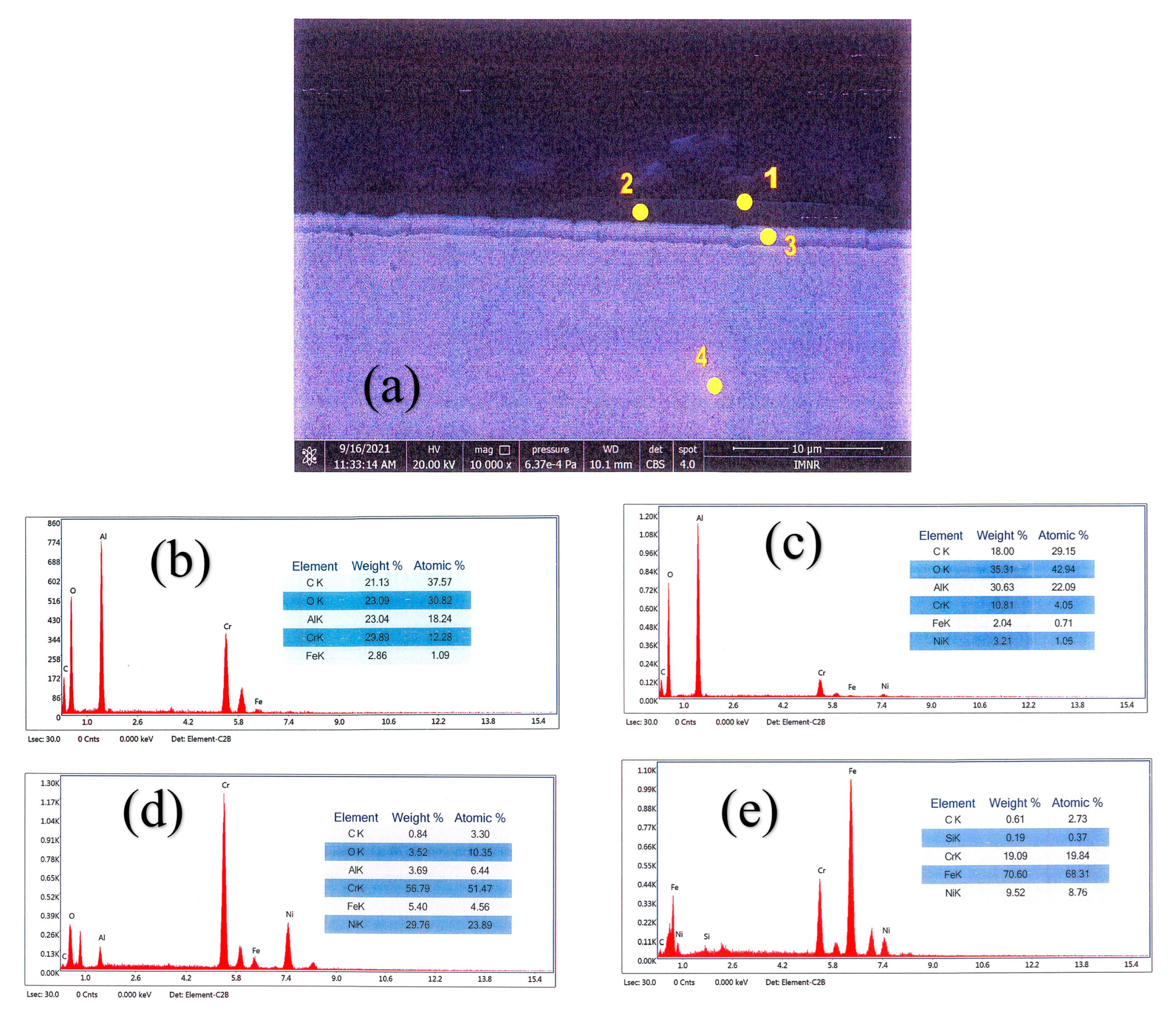
The cross-sectional SEM analysis, shown in Figure 1, reveals that two types of films, with a total thickness of approximately ~3 µm, were deposited on the substrate.
Figure 2a shows an SEM image of the layers deposited on the 316L steel specimen and the points where EDS analyses were performed. In Figure 2b, the EDS result obtained at point 1 is presented. This region corresponds to the alumina layer, and the main elements detected are Al and O. Additionally, Cr was also identified, which was deposited as a skinny, nanometer-scale layer on top of the alumina film. The analysis performed in point 2, still within the alumina layer but closer to the interior, shows a decrease in the Cr peak (Figure 2c), confirming that Cr was deposited especially on the surface.
In Figure 2d, the EDS analysis performed at point 3 shows a decrease in the concentrations of Al and O, while the concentrations of Cr and Ni increase. This region corresponds to the NiCrAlY interlayer. However, the yttrium content is very low and falls below the detection limit of EDS, although the manufacturer’s certificate for the powder used in the deposition indicates a concentration of approximately 0.9% The analysis at point 4, conducted in the substrate (316L steel), shows an increased Fe concentration, identifying it as the dominant element, with Cr and Ni also present in this region (Figure 2e).

3.2. Characterisation Using Optical Microscopy

Figure 3 illustrates the specimens following exposure to liquid lead at 550 °C under different oxygen concentrations. After extraction from the molten Pb, the sample surfaces remained covered with solidified lead.

3.2.1. Cross-Section Analysis

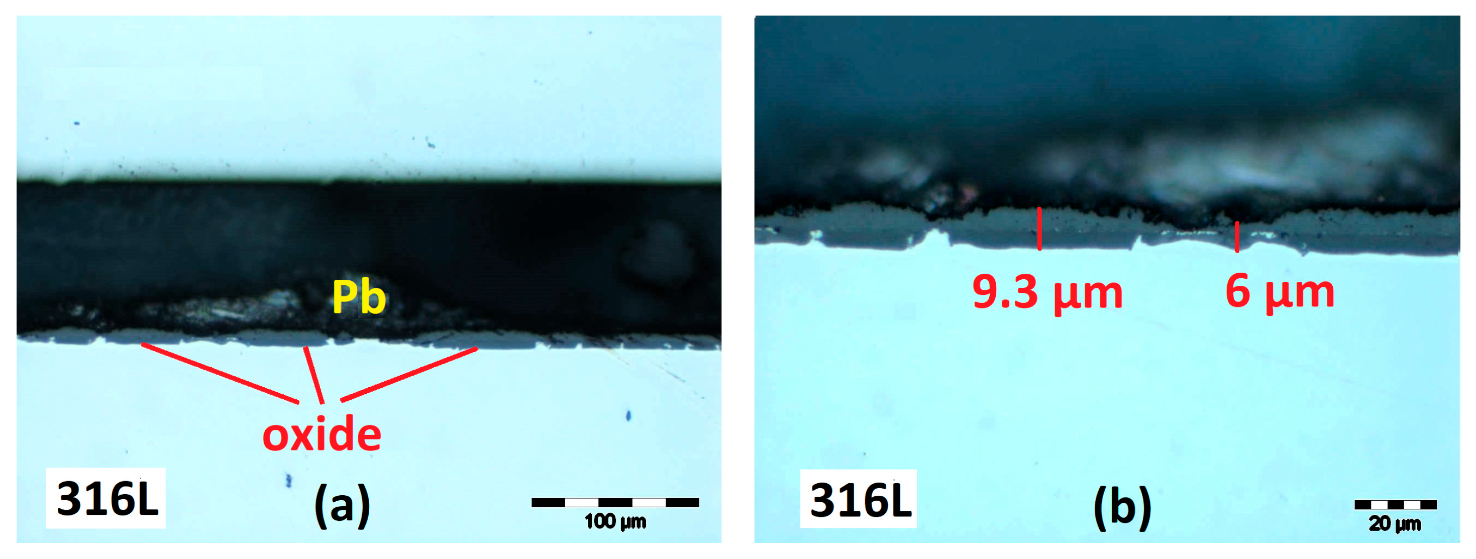
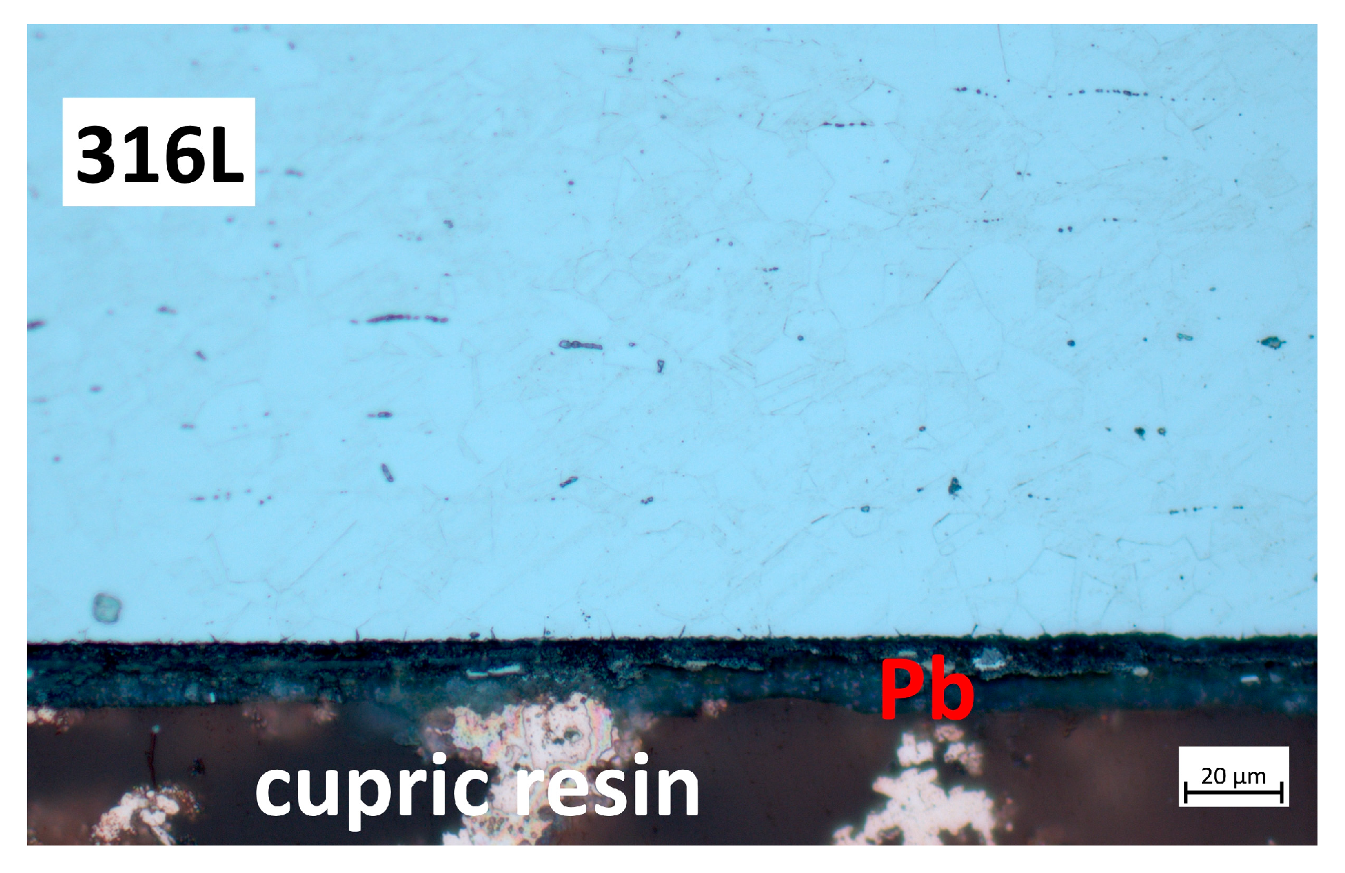
The micrographs from Figure 4 show that the uncoated 316L steel specimen tested for 1000 h in liquid lead at 550 °C under oxygen-saturated conditions exhibits an oxidation process. The thickness of the formed layer, measured in several areas, ranges between 6 µm and 9 µm.
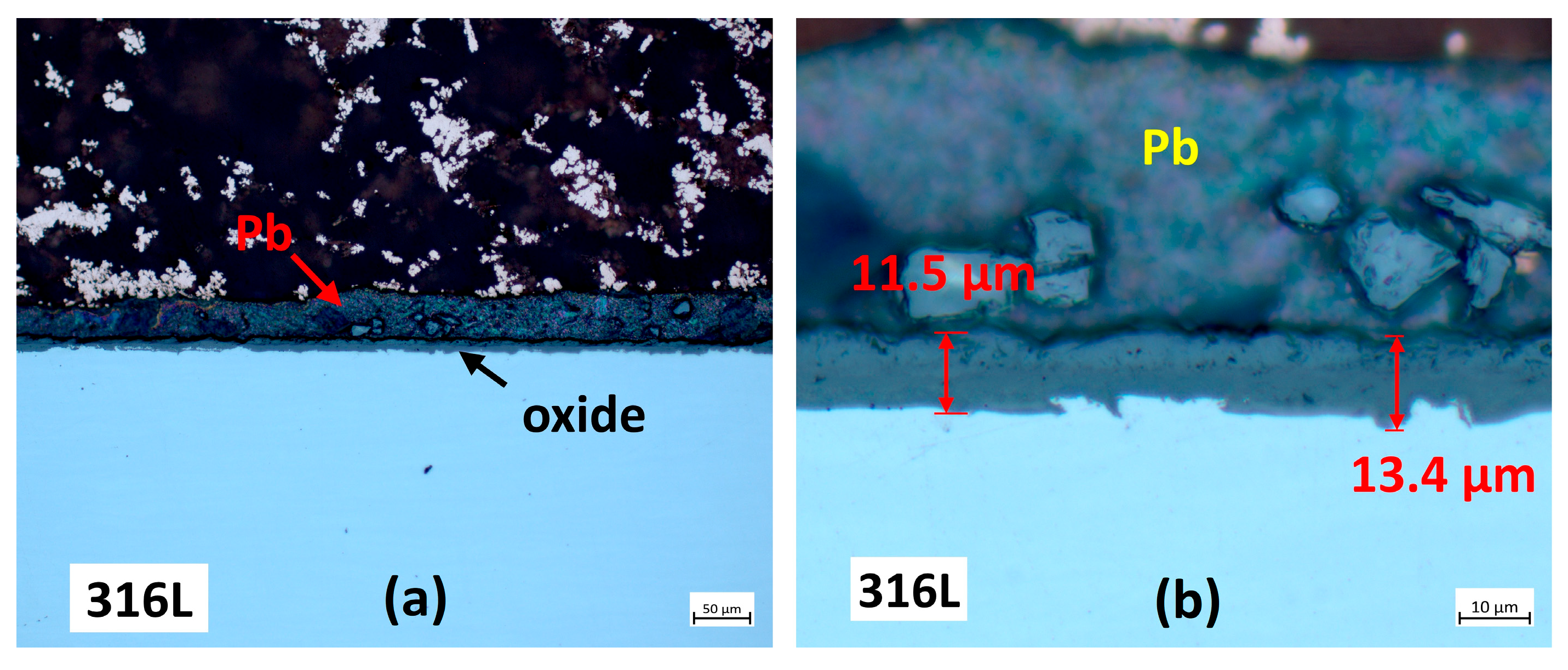
As illustrated in Figure 5, the uncoated 316L steel specimen exposed for 2000 h to liquid lead at 550 °C under oxygen-saturated conditions exhibits the same oxidation process. Compared with the specimen tested for 1000 h, in this case, the oxide layer tends to become more uniform and thicker, reaching an average thickness of 12 µm.
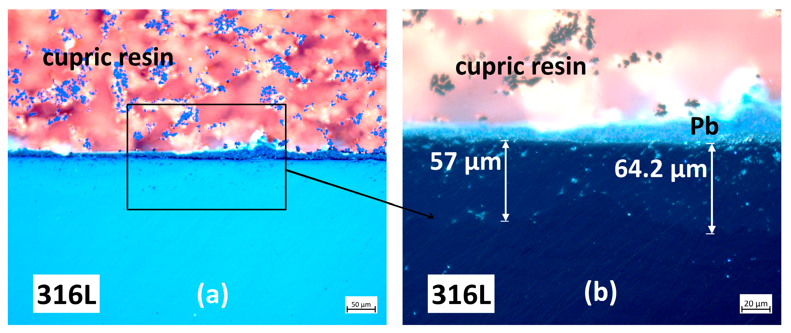
Figure 6a,b present cross-sectional micrographs of a 316L steel specimen tested in liquid lead at low oxygen content (550 °C, 1000 h, ~10−8 wt O2%). The micrographs were obtained using the Differential Interference Contrast (DIC) technique. DIC analysis reveals that no oxide formation occurred; moreover, lead appears to have penetrated the material to a depth of up to 64 µm in this area. At low dissolved oxygen concentrations, the austenitic stainless steels are unable to form or sustain a continuous protective oxide film, and the dominant degradation process is dissolution corrosion [34,35]. In this regime, metallic elements from the steel matrix dissolve directly into the liquid lead due to their finite solubility, with dissolution proceeding until saturation levels are reached in the melt [36].
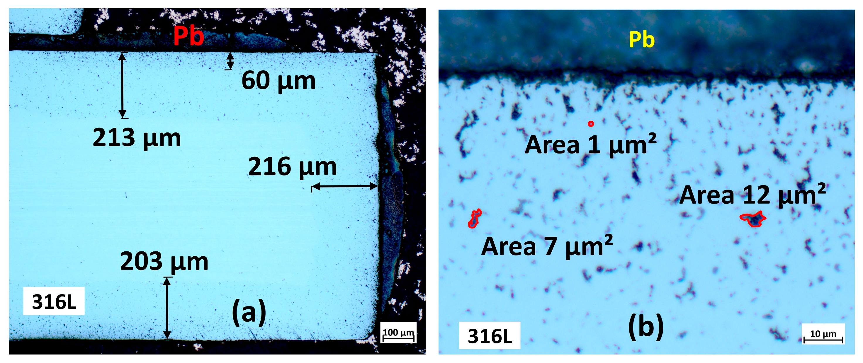
Figure 7a,b show cross-section micrographs of a 316L steel specimen coated with NiCrAlY and tested in liquid lead at low oxygen content (550 °C, 1000 h, ~10−8 wt.% O). This coating no longer provides protection and can no longer be reliably detected on the specimen surface. The bright-field images indicate that lead penetrated the material to an average depth of approximately 210 µm. Furthermore, the surface areas of individual lead particles within the 316L steel ranged from 1 to 12 µm2 in this particular zone. The lead particles are relatively widely distributed, and many exhibit significant surface areas. However, in other regions, the lead particles were larger.
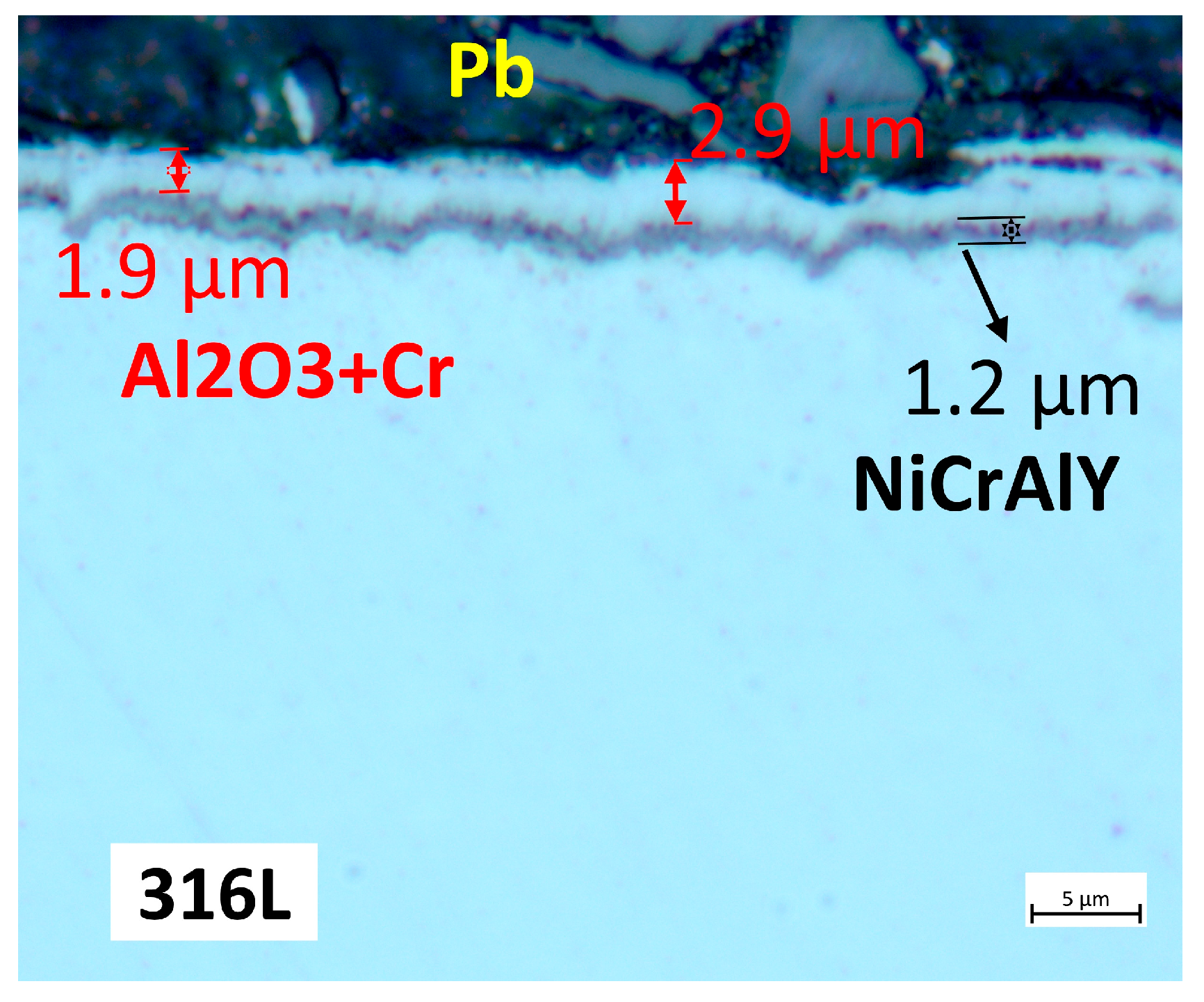
A cross-section micrograph of the 316L steel specimen coated with NiCrAlY/Al2O3 + Cr and exposed to liquid lead under low oxygen conditions (550 °C, 1000 h, ~10−8 wt.% O) is shown in Figure 8. In comparison with the specimen coated with a single layer, this specimen, tested under identical conditions, shows no evidence of material degradation or lead ingress into the steel matrix. In this region, the NiCrAlY film exhibited a thickness of 1.2 µm, whereas the Al2O3 + Cr layer was found to range between 1.9 and 2.9 µm. For the post-exposure characterisation of the thin-film-coated specimens, samples were sectioned from four distinct locations within the material.

3.2.2. Microstructural Analysis

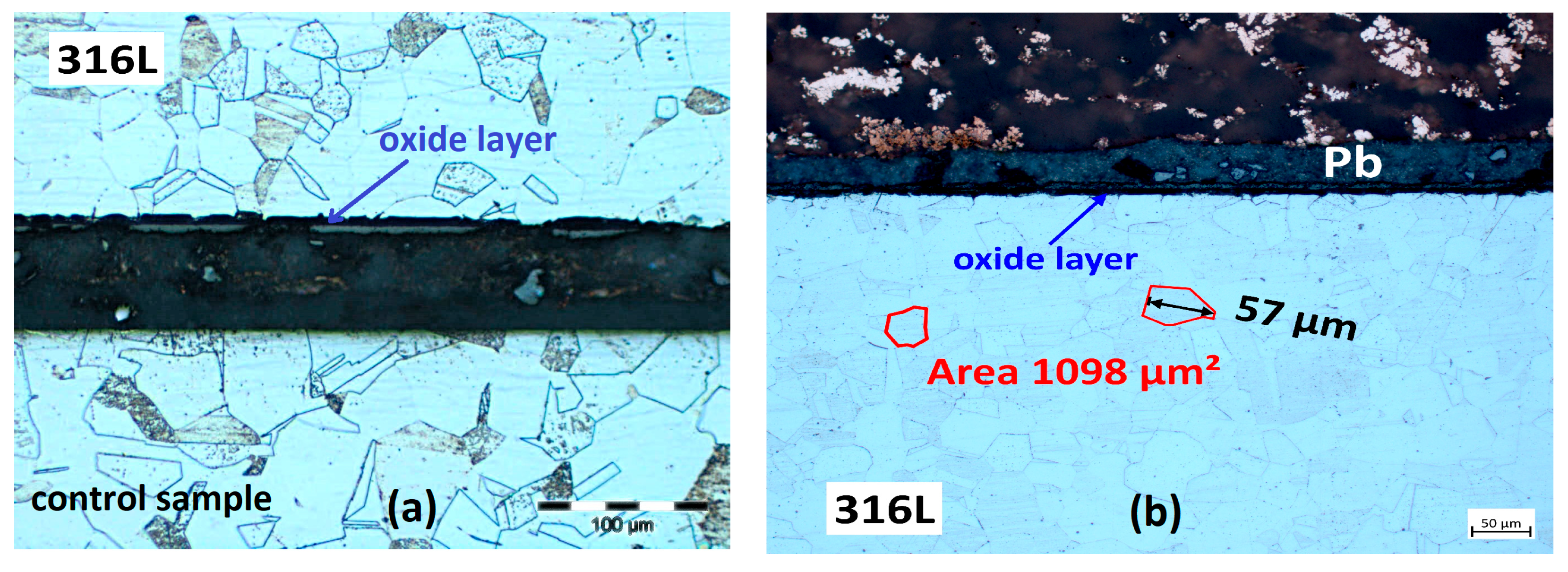
The microstructural analyses performed on 316L steel specimens tested for 1000 and 2000 h in liquid lead at oxygen saturation and 550 °C are presented in Figure 9a,b. In addition, the microstructure of a reference specimen is presented in Figure 9a (bottom). It can be observed that the reference specimens and those tested in liquid lead exhibit a microstructure consisting of polyhedral austenitic grains, occasionally twinned and with carbide precipitates. Since electrochemical etching deteriorates the oxide layer formed on the material surface, its observation is more difficult. However, the images indicate that lead had no impact on the austenitic structure and did not penetrate the steel.
The microstructural analyses of the 316L steel specimen tested in liquid lead (550 °C, 1000 h, ~10−8 wt.% O) are presented in Figure 10a,b. The images reveal generalised corrosion, with the austenitic microstructure affected to a considerable depth, resulting in steel degradation extending down to 101 µm in this region. Among the principal alloying elements, Ni exhibits the highest solubility and dissolution rate in Pb, which makes it the most vulnerable element [37]. Preferential removal of Ni from the austenitic matrix destabilises its structure and promotes transformation into ferrite, a phenomenon widely referred to as ferritization [38]. As Ni leaches out, Pb can infiltrate along grain boundaries and microstructural defects, further accelerating the degradation process [36].
These microstructural analyses demonstrated that AISI 316L steel tested in liquid lead at 550 °C exhibits different behaviour depending on the oxygen concentration. At high oxygen levels, the steel develops an oxide layer on the surface, whereas at low oxygen levels, it undergoes generalised corrosion, with the austenitic microstructure being altered.
Dissolution proceeds through a retreat of the solid–liquid interface, resulting in a porous, ferritized surface zone that lacks the alloying balance of the bulk steel. This zone typically shows lower hardness and reduced cohesion compared to the unaffected matrix, reflecting the depletion of Ni and Cr as well as the ingress of Pb [36,38].
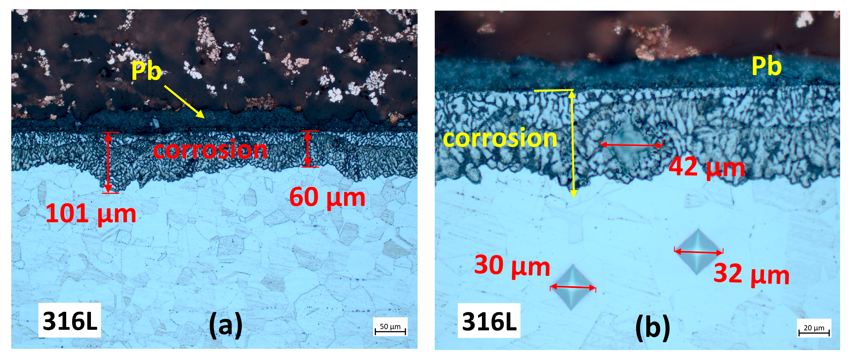
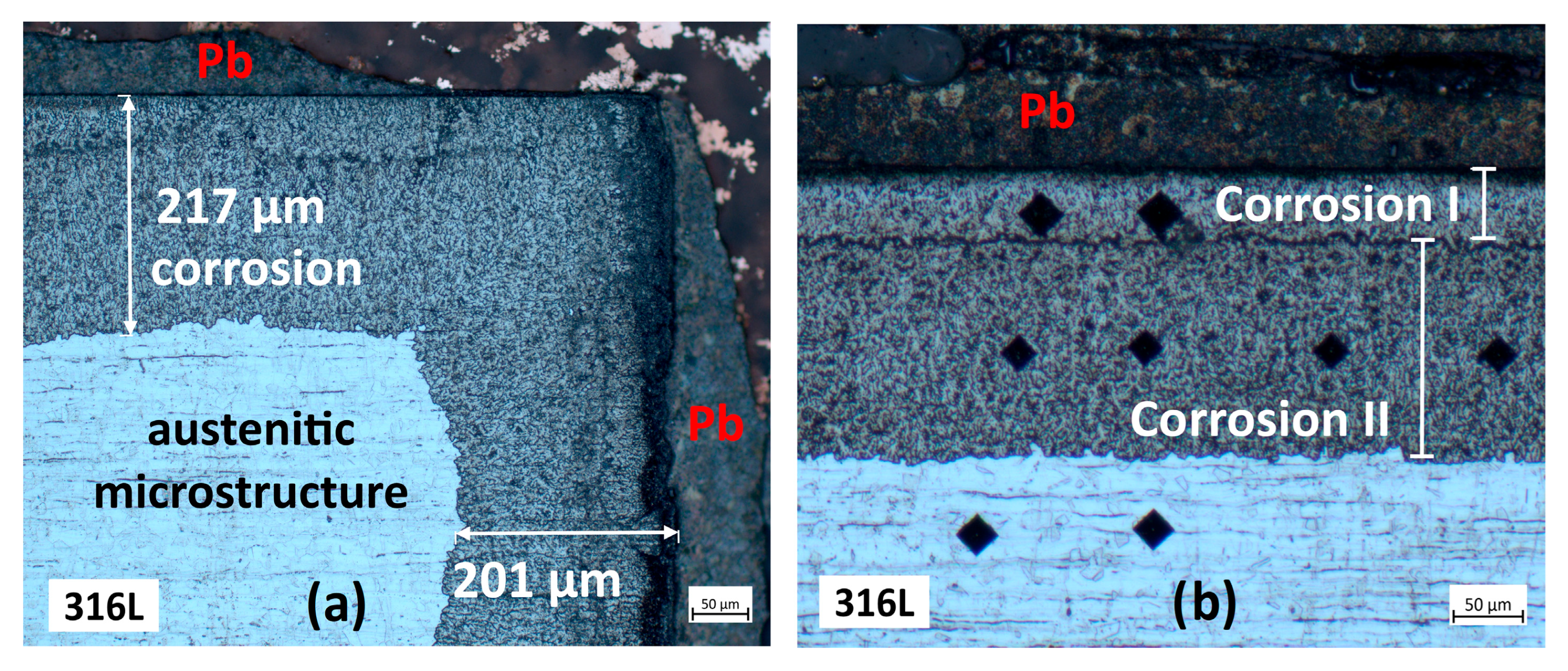
Figure 11a,b present the microstructural analyses of the 316L steel specimen coated with NiCrAlY and tested in liquid lead (550 °C, 1000 h, ~10−8 wt.% O). The micrographs reveal generalised corrosion, with the austenitic microstructure degraded to a considerable depth, reaching up to 217 µm in this region. Figure 11b reveals two distinct structural modifications: the first corrosion zone is characterised by very low hardness, whereas the second corrosion zone exhibits markedly high Vickers microhardness.
Figure 12 presents the microstructural features of the multilayer-coated specimen tested in liquid lead at low oxygen concentration (550 °C, 1000 h, ~10−8 wt.% O). The structure exhibits polyhedral grains, characteristic of an austenitic structure typical for 300-series stainless steels such as 316. Grain boundaries are sharp and continuous, with no evidence of intergranular attack. Within the grains, inclusions or dark linear features are visible, likely corresponding to sulphides, oxides, or carbides precipitated during metallurgical processing. Such inclusions and precipitates are common in industrial materials and do not necessarily indicate environmental degradation. Overall, the microstructure remains homogeneous and intact, showing no signs of ferritization, intergranular attack, or alloying element dissolution. The absence of selective attack or grain boundary penetration confirms that the specimen was not significantly affected, after 1000 h of exposure to liquid lead. It appears that the additional Al2O3 + Cr film deposited over the NiCrAlY coating has contributed to improved protection against corrosion. The main advantage of alumina (Al2O3) coatings for steels exposed to liquid lead lies in their thermodynamic stability and very low solubility in Pb, which ensures long-term protection of the substrate. Alumina is a chemically inert barrier that effectively suppresses both inward oxygen diffusion and outward dissolution of alloying elements such as Ni and Fe [15].

3.3. Characterisation Using Scanning Electron Microscopy (SEM)

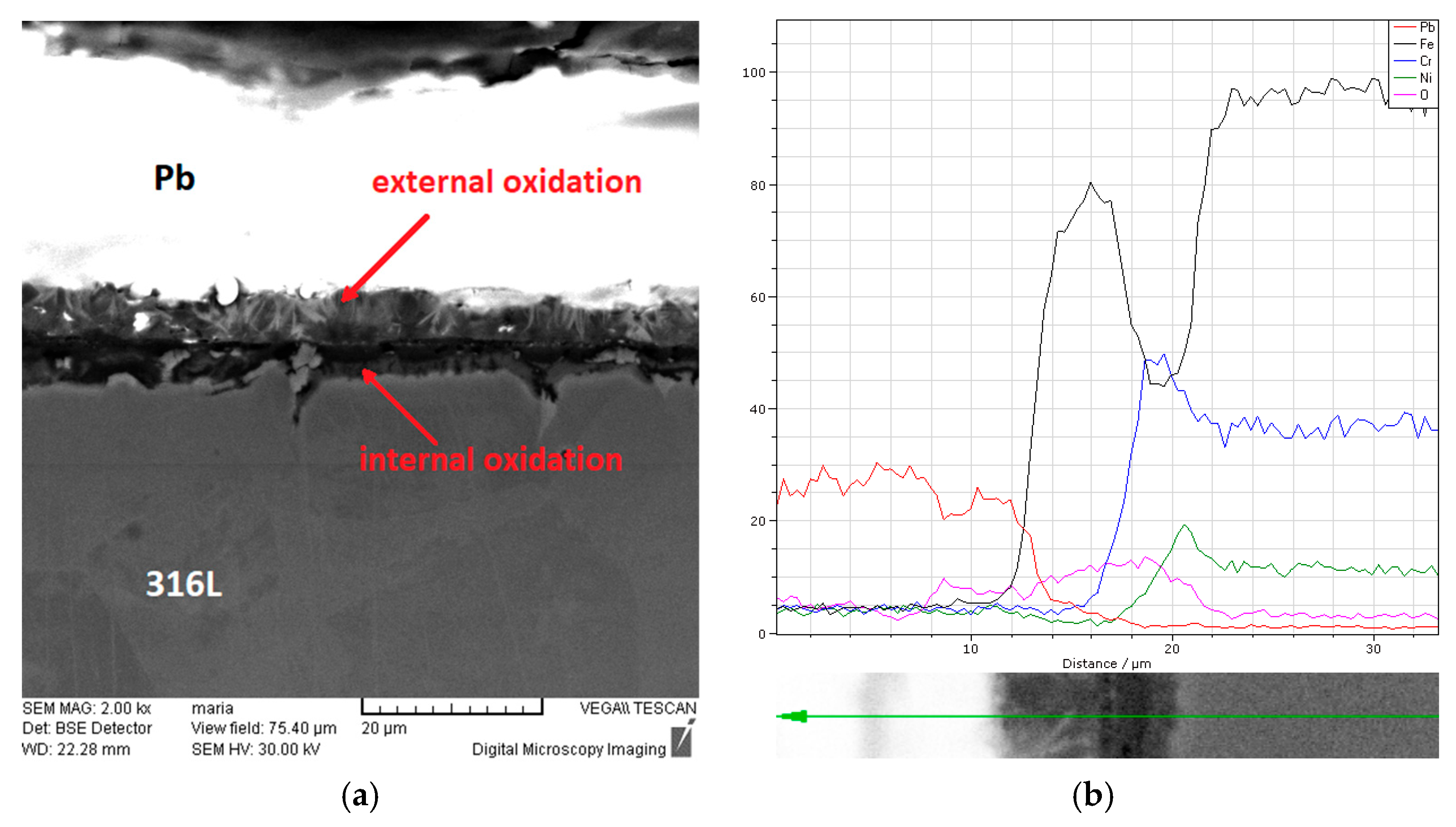
Figure 13 shows the SEM-EDS cross-section analysis of the specimen exposed to liquid lead for 2000 h under oxygen-saturated conditions (550 °C, 2000 h, ~10−3 wt.% O). The surface film consists of a duplex oxide layer, characterised by a porous outer region and a denser inner region. EDS analysis indicates that the outer layer is primarily an iron oxide, as Fe and O are the dominant elements. In the inner layer, the chromium peak surpasses that of iron, most likely due to the formation of an Fe–Cr spinel.
Similar morphologies have been reported in the literature for ODS, austenitic, and martensitic steels after long-term exposure to molten lead [39,40,41,42]. This structure reflects the underlying formation mechanism: oxygen atoms dissolved in the liquid metal adsorb on the steel surface and react with Fe and Cr. Iron ions diffuse toward the surface and form Fe3O4, while Cr promotes the formation of a denser spinel layer at the metal/oxide interface, often assisted by local heterogeneities such as grain boundaries and inclusions [43,44]. With prolonged exposure, this process leads to the development of a duplex structure: a porous outer magnetite (Fe3O4) layer and a compact, Cr-enriched spinel ((Fe,Cr)2O4) layer that adheres strongly to the substrate [45,46]. The protective properties of the film are mainly associated with the inner spinel, which limits both oxygen ingress and cation diffusion. In this stage, oxide growth follows diffusion-controlled kinetics, typically described by a parabolic rate law [47].
However, at high oxygen activity, the rapid thickening of the oxide leads to mechanical instabilities in the scale. Differential thermal expansion between oxide and steel, volume expansion associated with oxide formation, and the unequal diffusion of ions produce stresses and voids within the scale [44,47]. As a result, the outer magnetite layer is prone to cracking and delamination. Once spallation occurs, fresh metal is exposed, and the oxidation cycle restarts [48].
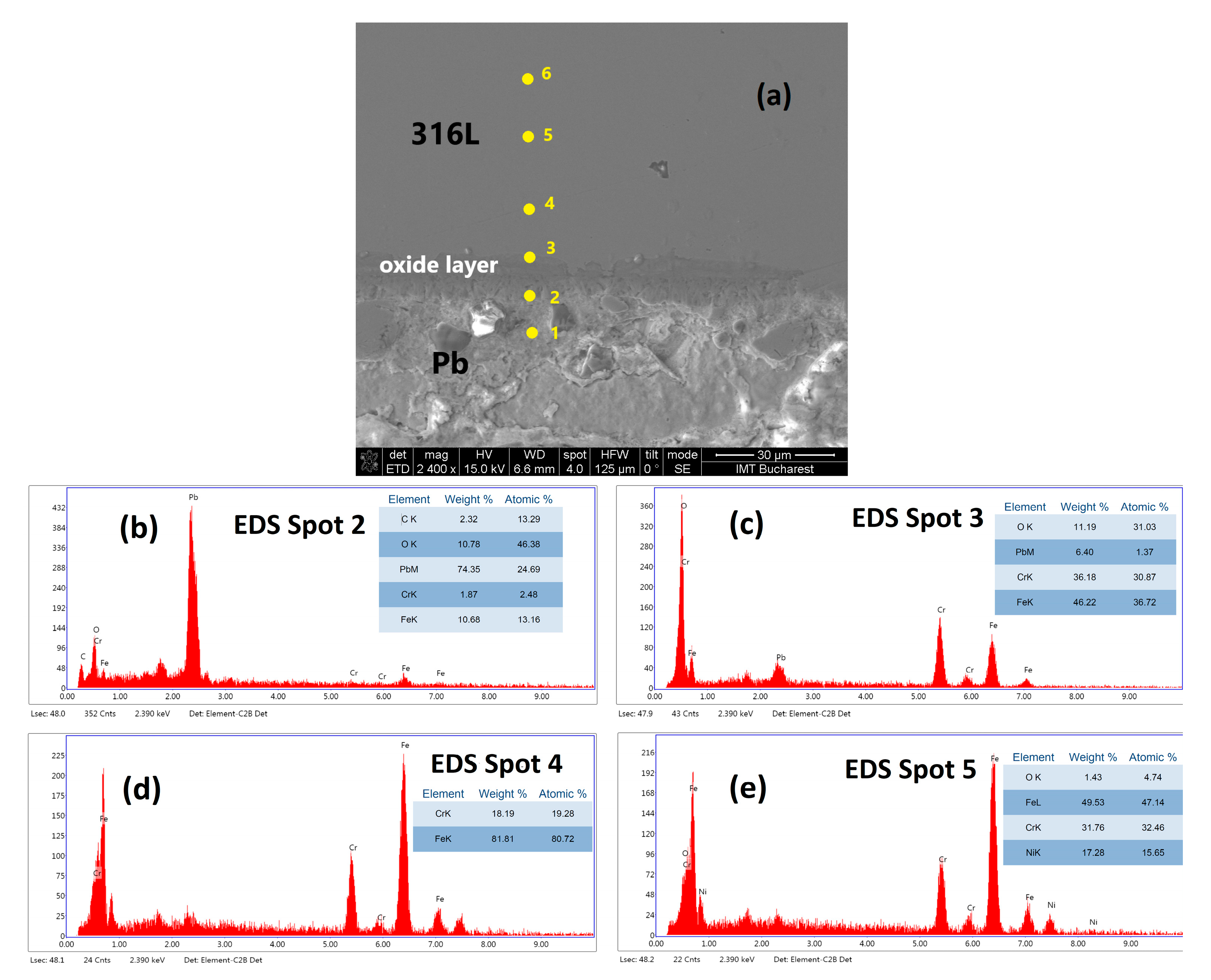
Figure 14 shows the SEM-EDS cross-section analysis of the specimen exposed to liquid lead for 1000 h under oxygen-saturated conditions (550 °C, 1000 h, ~10−3 wt.% O). Compared to the specimen tested for 2000 h, this sample exhibits a much thinner and non-uniform oxide film, which is more difficult to examine. The EDS spectra at spots 1 and 2 (Figure 14) indicates that lead is the predominant element, corresponding to solidified lead on the specimen surface. Spot 3 appears to be located in the internally oxidised zone, where oxygen, chromium, and iron are the main elements, with the chromium peak exceeding that of iron. Further, at spots 4, 5, and 6, iron becomes the major element, followed by chromium and nickel, the alloying elements of the 316L stainless steel.
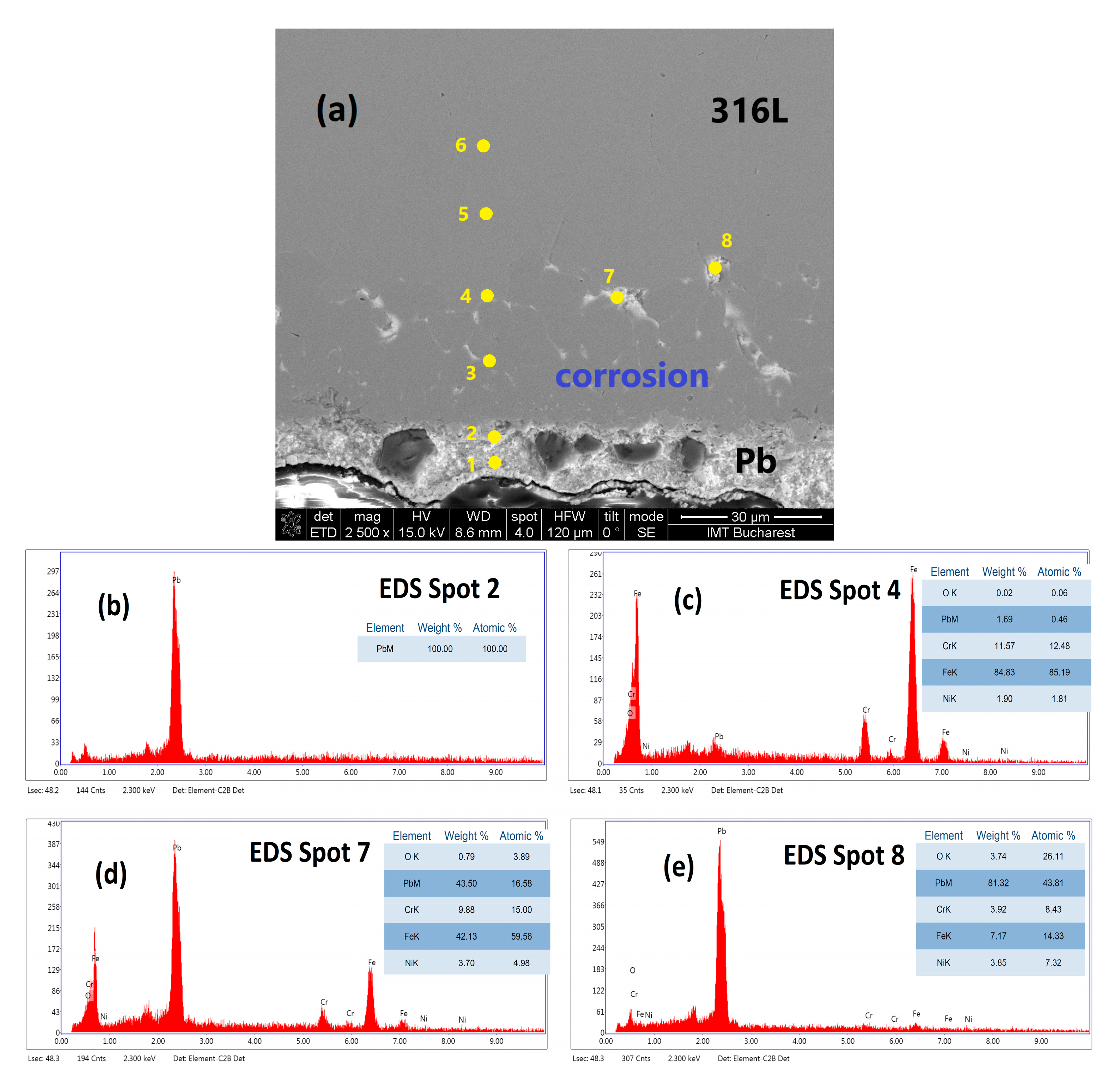
Figure 15 shows the SEM-EDS cross-section analysis of the specimen exposed to liquid lead for 1000 h at low oxygen concentration (550 °C, 1000 h, ~10−8 wt.% O). The EDS analyses indicate that in the region corresponding to spots 1 and 2, only lead is present. Here is the solidified lead layer on the material surface. Furthermore, the major elements identified at spot 4 are iron, chromium, and nickel, which are the constitutive elements of 316L steel. However, moving deeper into the material, analysis from spots 7 and 8 reveals lead as the predominant element. The EDS analysis thus confirms the structural changes induced by lead penetration into the material, as also observed with the optical microscopy investigation.
Unlike oxidation-controlled corrosion, dissolution does not self-limit. Without sufficient dissolved oxygen to trigger the nucleation of protective oxides such as Fe3O4 or Fe–Cr spinel, the corrosion process continues, and the depth of material loss increases with exposure time. Thus, dissolution corrosion under oxygen-poor conditions is considered the most damaging regime for austenitic steels in Pb or LBE environments [32,33].
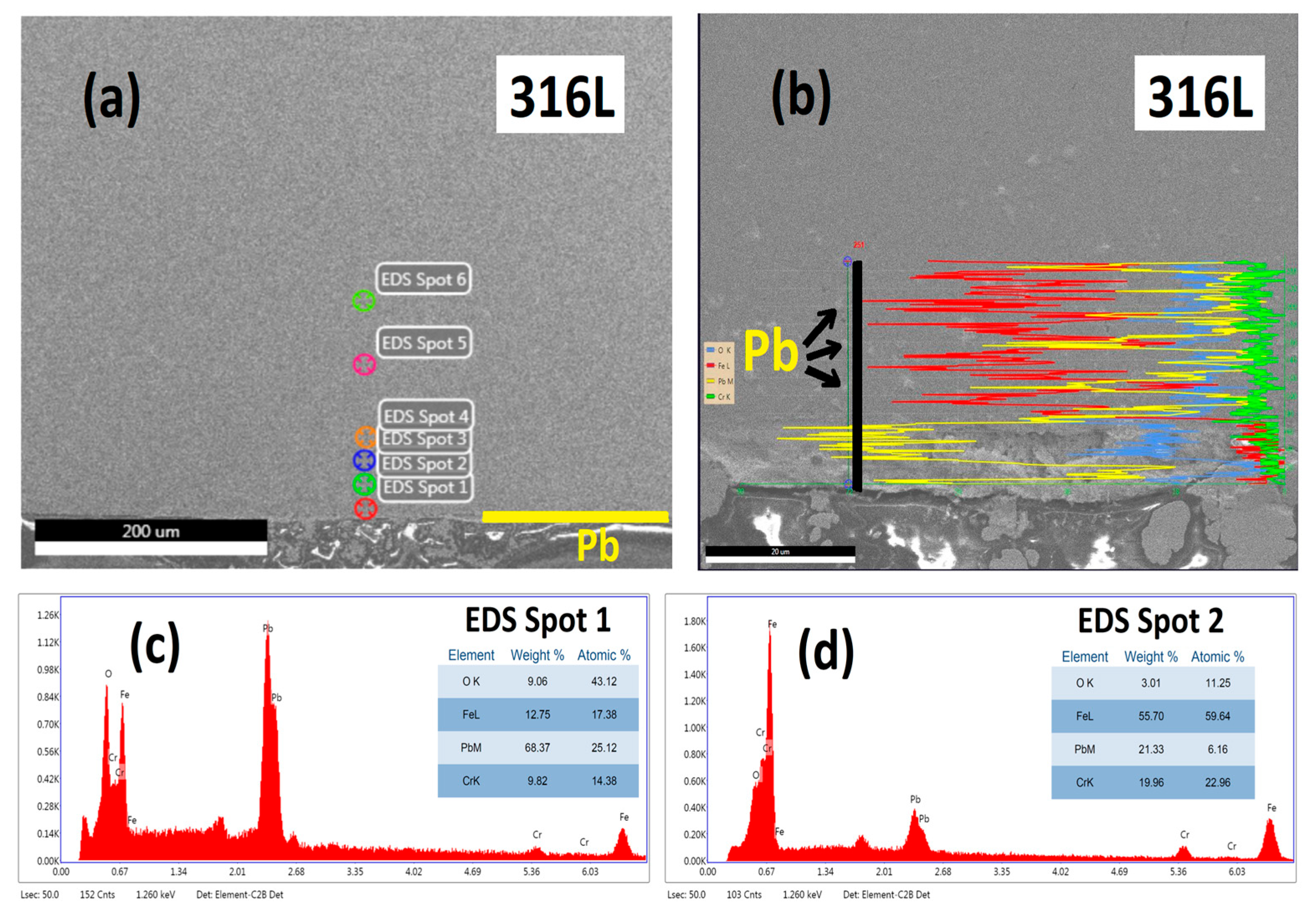
Figure 16 presents the SEM-EDS cross-section analyses of the 316L stainless steel specimen coated with NiCrAlY and tested in liquid lead (550 °C, 1000 h, ~10−8 wt.% O). The EDS spectra shown in Figure 16c,d indicate the presence of lead in spots 1 and 2, with lead being the predominant element in the first region. Due to the lower lead concentrations in spots 3 and 4, a line scan analysis was conducted at higher magnification. This scan was deliberately selected to pass through specific regions containing suspected particles. Following this analysis (Figure 16b), it was determined that those suspected formations correspond to lead particles. Furthermore, this investigation confirms the structural changes observed in optical microscopy, indicating that the NiCrAlY coating did not confer protective properties.
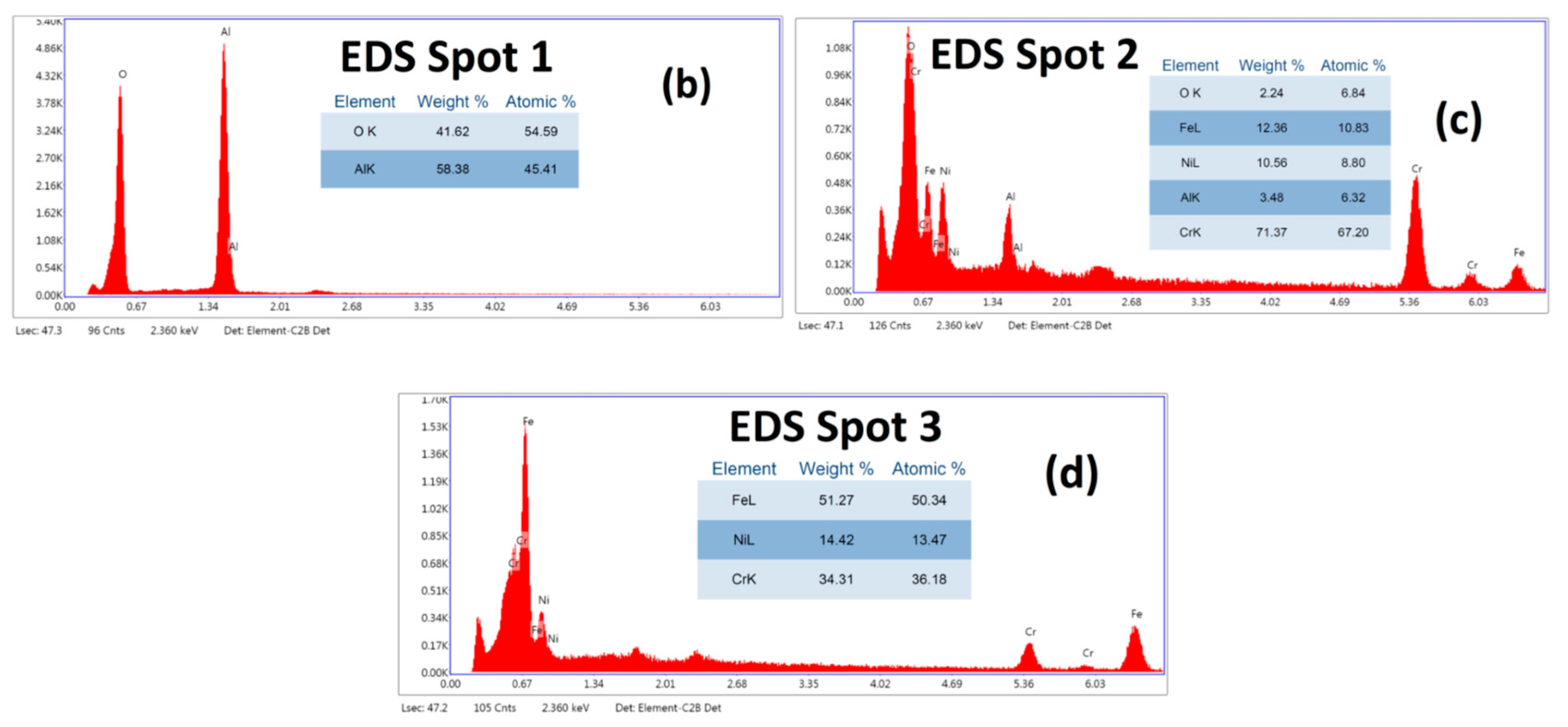
Figure 17 presents the SEM-EDS cross-section analyses of the 316L steel specimen multi-layer coated with NiCrAlY/Al2O3 + Cr and tested in liquid lead (550 °C, 1000 h, ~10−8 wt.% O). In this case, no lead inclusions were detected within the 316L steel matrix, in contrast to the single-layer NiCrAlY-coated specimen, where lead particles were identified. The EDS spectrum acquired in Spot 1 revealed aluminium and oxygen as the dominant elements, consistent with the presence of the deposited Al2O3 layer. The subsequently deposited metallic chromium, with an initial thickness of 100–200 nm, could not be determined, especially in cross-section, due to its extremely small thickness. At Spot 2, corresponding to the NiCrAlY inter-layer, chromium was detected as the major element, accompanied by nickel, iron, and aluminium. Yttrium could not be quantified, as its concentration in the feedstock powder was below 0.9%. The presence of iron in this spot can be attributed to the very limited thickness of the intermediate layer (~1 µm), which allows partial signal acquisition from the steel matrix, where iron is the principal constituent. Finally, the spectrum in Spot 3 confirmed the compositional elements of the 316L stainless steel matrix (Fe, Cr, Ni), with iron being predominant.

3.4. Vickers Microhardness

For the specimen tested in lead at a low oxygen concentration (550 °C, 1000 h, ~10−8 wt.% O), the average Vickers microhardness measured near the surface, close to the corroded region, was 181 HV0.1. Within the corroded zone, the microhardness decreased markedly to 105 HV0.1, suggesting a phase transformation from austenitic microstructure. In contrast, the specimen core exhibited a microhardness of 185 HV0.1. The reference specimen showed Vickers microhardness values of 174 HV0.1 in the core and 178 HV0.1 at the edge. The specimen tested for 1000 h under oxygen-saturated conditions presented an average microhardness value of 176 HV0.1, closely matching that of the reference specimen. In the case of the specimen exposed for 2000 h under oxygen-saturated conditions, the average microhardness was 161 HV0.1 near the surface and 167 HV0.1 in the core. Here, the slight decrease in microhardness is most likely attributable to the relief of some residual stresses.
The Vickers microhardness profile of the 316L steel specimen coated with NiCrAlY and tested in liquid lead (550 °C, 1000 h, ~10−8 wt.% O) reveals two distinct corrosion zones. The first zone shows very low hardness, averaging 143 HV0.1, while the second zone exhibits a markedly higher hardness of 240 HV0.1—about 55 units greater than that measured in the unaffected austenitic region of the same specimen.
Compared with the reference specimen, the Vickers microhardness values of the multilayer-coated sample increased slightly by about 16 units, both in the core and at the edge. This enhancement may be attributed to carbide precipitation.

4. Conclusions

This study demonstrates that the corrosion resistance of 316L austenitic stainless steel in liquid lead at 550 °C is strongly influenced by the dissolved oxygen concentration and the presence of protective coatings. Under oxygen-saturated conditions (~10−3 wt.% O), the steel specimens tested for 1000 h and 2000 h developed a duplex oxide scale composed of a porous Fe–O outer layer and a denser Cr-enriched Fe–Cr–O inner layer. While this structure offered partial protection, its thickness increased with exposure time, and its long-term stability may be limited by cracking and spallation of the outer magnetite. In contrast, when the oxygen level was reduced to ~10−8 wt.% O, protective oxides could not be sustained, and dissolution corrosion dominated. Selective Ni leaching destabilised the austenitic matrix, leading to ferritization, Pb infiltration, and severe generalised attack extending 100–200 µm below the surface. Microhardness profiling revealed distinct zones of reduced hardness, consistent with phase transformations and microstructural alteration caused by selective dissolution.
Coating strategies on 316L steels were also evaluated under low-oxygen conditions (~10−8 wt.% O). The ~1 µm EB-PVD NiCrAlY single-layer coating failed to block Pb penetration; extensive corrosion and substrate degradation similar to that of uncoated specimens were observed after 1000 h of exposure. In contrast, the ~3 µm multilayer system consisting of a NiCrAlY interlayer, an Al2O3 second layer, and a 100–200 nm metallic Cr top film exhibited good stability. After 1000 h in low-oxygen liquid lead, no evidence of corrosion or Pb ingress was detected, and the austenitic microstructure remained intact. This protective effect is attributed to the diffusion characteristics of the Al2O3 layer, which, due to its dense, thermodynamically stable structure, acts as an effective barrier that suppresses both outward diffusion of alloying elements (e.g., Fe, Ni, Cr) and inward diffusion of oxygen. At grain boundaries, which normally serve as fast diffusion paths, the alumina layer significantly slows down transport due to its chemical inertness and low defect mobility. This grain-boundary diffusion resistance is a key factor in its protective performance in Pb environments.
Overall, the findings highlight the critical role of oxygen control in liquid lead systems and demonstrate the effectiveness of engineered multilayer coatings in improving the corrosion resistance of austenitic steels. Such results provide valuable guidance for the design of long-term protective strategies in lead-cooled reactor environments, where oxygen control is difficult to maintain and structural integrity is critical for safety and performance.

Author Contributions

Conceptualization, D.P., F.G., M.C., O.B. and I.D.; methodology, D.P., O.B. and M.C.; software, D.P., O.B. and M.C.; validation, F.G. and I.D.; formal analysis, D.P.; investigation, F.G.; data curation, D.P. and M.C.; writing—original draft preparation, D.P., F.G. and I.D.; writing—review and editing, F.G. and I.D.; visualization, D.P., O.B., M.C. and I.D.; supervision, F.G. and I.D. All authors have read and agreed to the published version of the manuscript.

Funding

This research was funded by a grant from the National Program for Research of the National Association of Technical Universities grant number GNAC ARUT 2023.

Institutional Review Board Statement

Not applicable.

Informed Consent Statement

Not applicable.

Data Availability Statement

The raw data supporting the conclusions of this article will be made available by the authors upon request.

Acknowledgments

This work was supported by a grant from the National Program for Research of the National Association of Technical Universities—GNAC ARUT 2023.

Conflicts of Interest

The authors declare no conflicts of interest.

References

  1. Lucan, D.; Jinescu, G. Materials and Specific Processes for Heat Transfer Equipment in Generation IV Fission Reactors; Eikon: Bucuresti, Romania, 2023; p. 19. [Google Scholar]
  2. Pioro, I.L. Handbook of Generation IV Nuclear Reactors; Elsevier: Amsterdam, The Netherlands, 2016. [Google Scholar] [CrossRef]
  3. Kelly, J.E. Generation IV International Forum: A decade of progress through international cooperation. Progr. Nucl. Energy 2014, 77, 240–246. [Google Scholar] [CrossRef]
  4. Stanculescu, A. GIF R&D outlook for generation IV nuclear energy systems: 2018 update. In Proceedings of the Generation IV International Forum, Paris, France, 18–19 March 2018; pp. 16–18. [Google Scholar]
  5. Tudose, A.E.; Golgovici, F.; Anghel, A.; Fulger, M.; Demetrescu, I. Corrosion Testing of CrNx-Coated 310 H Stainless Steel under Simulated Supercritical Water Conditions. Materials 2022, 15, 5489. [Google Scholar] [CrossRef] [PubMed]
  6. Trubcheninova, A.I.; Abramov, A.V.; Alimgulov, R.R.; Polovov, I.B.; Volkovich, V.A. The Effect of Microstructural Changes in Nickel-Based Alloys on Their Corrosion Resistance in Molten Halides: A Consideration of Prospective Structural Materials for Molten Salt Reactors. Appl. Sci. 2025, 15, 4753. [Google Scholar] [CrossRef]
  7. Ding, H.; Tong, J.; Wang, Y.; Zhang, L. Development of emergency planning zone for high temperature gas-cooled reactor. Ann. Nucl. Energy 2018, 111, 347–353. [Google Scholar] [CrossRef]
  8. Cheng, S.; Xu, R. Molten-Pool Mobility. In Safety of Sodium-Cooled Fast Reactors; Springer: Singapore, 2021; p. 32. ISBN 978-981-16-6115-0. [Google Scholar]
  9. Burakovsky, L.; Preston, D.L.; Green, A.A. Analytic Model for U-Nb Liquidus and U-6Nb Melting Curve. Appl. Sci. 2025, 15, 3763. [Google Scholar] [CrossRef]
  10. Teng, F.; Copeland-Johnson, T.M.; Tucker, J.D.; Cao, G. Accelerated corrosion of Ni-based alloys in molten chloride salts, due to Ni2Cr phase formation. Materialia 2023, 31, 101875. [Google Scholar] [CrossRef]
  11. Petrescu, D.; Fulger, M.; Golgovici, F.; Demetrescu, I. Addressing some issues encountered in liquid lead corrosion tests of candidate materials for future nuclear reactors. U.P.B. Sci. Bull. Ser. B 2022, 84, 89–97. [Google Scholar]
  12. Zhang, C.; Chen, L. Advancements and Development Trends in Lead-Cooled Fast Reactor Core Design. Processes 2025, 13, 1773. [Google Scholar] [CrossRef]
  13. NEA. Handbook on Lead-Bismuth Eutectic Alloy and Lead Properties, Materials Compatibility, Thermal-Hydraulics and Technologies—2015 Edition; OECD Publishing: Paris, France.
  14. García Ferré, F.; Mairov, A.; Iadiciccoa, D.; Vanazzi, M.; Bassini, S. Corrosion and radiation resistant nanoceramic coatings for lead fast reactors. Corros. Sci. 2017, 124, 80–92. [Google Scholar] [CrossRef]
  15. Zhang, J. A review of steel corrosion by liquid lead and lead-bismuth. Corros. Sci. 2009, 51, 1207–1227. [Google Scholar] [CrossRef]
  16. Weisenburger, A.; Schroer, C.; Jianu, A. Long term corrosion on T91 and AISI 316L steel in flowing lead alloy and corrosion protection barrier development: Experiments and models. J. Nucl. Mater. 2011, 415, 260–269. [Google Scholar] [CrossRef]
  17. Konys, J.; Krauss, W. Corrosion of structural materials in liquid lead alloys for nuclear applications. Corrosion 2007, 63, 1124–1137. [Google Scholar] [CrossRef]
  18. Schroer, C.; Wedemeyer, O. Aspects of minimizing steel corrosion in liquid lead-alloys by addition of oxygen. Nucl. Eng. Des. 2011, 241, 4913–4923. [Google Scholar] [CrossRef]
  19. Caro, M.; Woloshun, K. Heavy liquid metal corrosion of structural materials in advanced nuclear materials. JOM 2013, 65, 1057–1066. [Google Scholar] [CrossRef]
  20. Hosemann, P.; Dickerson, R. Transmission electron microscopy (TEM) on oxide layers formed on D9 stainless steel in lead bismuth eutectic (LBE). Corros. Sci. 2013, 66, 196–202. [Google Scholar] [CrossRef]
  21. Gong, X.; Short, M.P.; Auger, T. Environmental degradation of structural materials in liquid lead-and lead-bismuth eutectic-cooled reactors. Prog. Mater. Sci. 2022, 126, 100920. [Google Scholar] [CrossRef]
  22. Qin, B.; Fu, X.G. Preliminary experiment study on control of oxygen concentration via gas phase in liquid lead-bismuth alloy. Mater. Rep. 2019, 33, 1821–1824. [Google Scholar]
  23. Liu, Y.; Qin, B.; Fu, X. Influence of Surface State on the Corrosion Behavior of Si-Reinforced F/M Steels under Solid-Phase Oxygen-Controlled Static Liquid LBE Environment. Metals 2024, 14, 810. [Google Scholar] [CrossRef]
  24. Petrescu, D.; Nitu, A.; Golgovici, F.; Demetrescu, I. Behaviour Aspects of an EB-PVD Alumina (Al2O3) Film with an Interlayer (NiCrAlY) Deposited on AISI 316L Steel Investigated in Liquid Lead. Metals 2023, 13, 616. [Google Scholar] [CrossRef]
  25. Weisenburger, A.; Mansani, L.; Schumacher, G. Oxygen for protective oxide scale formation on pins and structural material surfaces in lead-alloy cooled reactors. Nucl. Eng. Des. 2014, 273, 584–594. [Google Scholar] [CrossRef]
  26. Wu, J.; Wu, R.; Wang, Y. Prediction of Dissolved Impurities and Movement of Oxide Particles in the Primary Circuit of LBE Fast Reactor. Coatings 2021, 11, 1263. [Google Scholar] [CrossRef]
  27. Li, Q.; Zhong, Y. Microstructure, Mechanical Properties, and Lead–Bismuth Eutectic Corrosion Behaviors of FeCrAlY-Al2O3 Nanoceramic Composite Coatings. Coatings 2024, 14, 393. [Google Scholar] [CrossRef]
  28. Heinzel, A.; Weisenburger, A. Corrosion behavior of austenitic steels in liquid lead bismuth containing 10−6 wt% and 10−8 wt% oxygen at 400–500 °C. J. Nucl. Mater. 2014, 448, 163–171. [Google Scholar] [CrossRef]
  29. Zhang, W.; Zhong, Y. Screening of the FeCrAl LBE corrosion-resistant coatings: The effect of Cr and Al contents. Surf. Coat. Technol. 2023, 462, 129477. [Google Scholar] [CrossRef]
  30. ASTM International. Standard Specification for Chromium and Chromium-Nickel Stainless Steel Plate, Sheet, and Strip for Pressure Vessels and for General Applications (ASTM A240/A240M-17); ASTM International: West Conshohocken, PA, USA, 2017. [Google Scholar] [CrossRef]
  31. ASTM International. Standard Practices for Detecting Susceptibility to Intergranular Attack in Austenitic Stainless Steels, ASTM A262; ASTM International: West Conshohocken, PA, USA, 2015. [Google Scholar] [CrossRef]
  32. Inspection certificate no. 783863/08.08.2017. Product 316L Steel, Outokumpu Stainless Oy. Tornio, Finland, 2017. certificate.tornio@outokum.com.
  33. Golgovici, F.; Tudose, A.-E.; Mosinoiu, L.F.; Demetrescu, I. Characterization of NiCrAlY Layers Deposited on 310H Alloy Using the EB-PVD Method After Oxidation in Water at High Temperature and Pressure. Appl. Sci. 2025, 15, 2361. [Google Scholar] [CrossRef]
  34. Serag, E. Corrosion behavior of steels in oxygenated liquid lead environments. Crystals 2022, 12, 968. [Google Scholar]
  35. Weisenburger, A.; Müller, G.; Schroer, C.; Heinzel, A.; Fazio, C. Corrosion and protection of steels in liquid lead and LBE: Mechanisms and oxygen control. J. Nucl. Mater. 2011, 415, 260–269. [Google Scholar] [CrossRef]
  36. Charalampopoulou, E.; Müller, G.; Weisenburger, A.; Heinzel, A. Selective leaching and ferritization of 316L stainless steel in LBE at low oxygen. J. Nucl. Mater. 2019, 516, 165–174. [Google Scholar]
  37. Yamaki, T.; Konishi, T.; Takahashi, M.; Kasahara, K. Dissolution kinetics of 316L stainless steel in low-oxygen LBE. J. Nucl. Mater. 2015, 456, 231–240. [Google Scholar]
  38. Hosemann, P.; Kondo, S.; Weisenburger, A.; Heinzel, A.; Müller, G.; Pereiro, A.; Gröschel, F.; Schroer, C.; Abe, H. Ferritization of austenitic steels in LBE under low oxygen conditions. Acta Mater. 2010, 58, 2813–2821. [Google Scholar]
  39. Di Gabriele, F.; Amore, S.; Scaiola, C. Corrosion behavior of 12Cr-ODS steel in molten lead. Nucl. Eng. Des. 2014, 280, 69–75. [Google Scholar] [CrossRef]
  40. Navas, M.; Hernandez, R. Compatibility of Structural Materials with Lead and Lead Bismuth Eutectic for CSP Applications. AIP Conf. Proc. 2018, 2033, 230009. [Google Scholar] [CrossRef]
  41. Vogt, J.-B.; Serre, I.P. A Review of the Surface Modifications for Corrosion Mitigation of Steels in Lead and LBE. Coatings 2021, 11, 53. [Google Scholar] [CrossRef]
  42. Cionea, C.; Abad, M.D.; Aussat, Y.; Frazer, D. Oxide scale formation on 316L and FeCrAl steels exposed to oxygen controlled static LBE at temperatures up to 800 °C. Sol. Energy Mater. Sol. Cells 2016, 144, 235–246. [Google Scholar] [CrossRef]
  43. Serag, E.; Caers, B.; Schuurmans, P.; Lucas, S.; Haye, E. Challenges and coating solutions for wear and corrosion inside lead–bismuth eutectic: A review. Surf. Coat. Technol. 2022, 441, 128542. [Google Scholar] [CrossRef]
  44. Popovic, M.; Chen, K.; Shen, H.; Stan, C.; Olmsted, D.; Tamura, N.; Asta, M.; Abad, M.; Hosemann, P. A study of deformation and strain induced in bulk by the oxide layer formation on a Fe–Cr–Al alloy in high-temperature liquid Pb–Bi eutectic. Acta Mater. 2018, 151, 301–309. [Google Scholar] [CrossRef]
  45. Ma, Z.; Shen, T.; Zhou, T.; Wang, Z. Performance of the new ferritic/martensitic steel SIMP against liquid lead–bismuth eutectic corrosion: Comparison with T91 and 316L steels. Mater. Corros. 2023, 74, 221–232. [Google Scholar]
  46. Tian, S.; Pang, Y.; Jiang, Z.; Luo, L.; Xiao, Z. Corrosion characteristics of T91 steel in lead–bismuth eutectic with different oxygen concentrations at 500 °C. Mater. Corros. 2022, 73, 134–142. [Google Scholar]
  47. Lee, S.G.; Shin, Y.-H.; Park, J.; Hwang, I.S. High-temperature corrosion behaviors of structural materials for lead-alloy-cooled fast reactor application. Appl. Sci. 2021, 11, 2349. [Google Scholar] [CrossRef]
  48. Orlov, S.N.; Bogachev, N.A.; Mereshchenko, A.S.; Zmitrodan, A.A.; Skripkin, M.Y. Electrochemical sensors for controlling oxygen content and corrosion processes in lead–bismuth eutectic coolant—State of the art. Sensors 2023, 23, 812. [Google Scholar] [CrossRef] [PubMed]
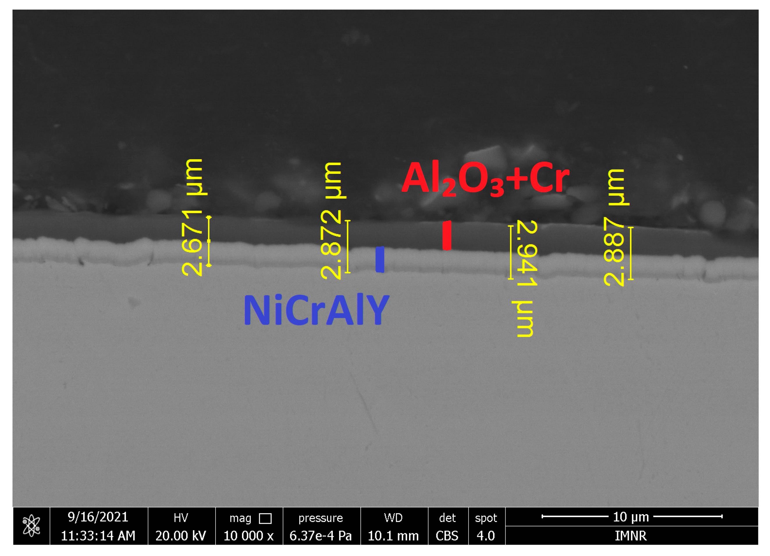
Figure 1. SEM cross-sectional image showing the thickness of the films deposited on the 316L steel sample.
Applsci 15 10572 g001
Figure 2. (a) Cross-section SEM image indicating the areas chosen for EDS investigation; (be) EDS analyses performed at different locations across the cross-section of the 316L steel sample coated with thin films: (b) area 1, (c) area 2, (d) area 3, (e) area 4.
Applsci 15 10572 g002
Figure 3. Steel specimens tested in liquid lead: (a) 316L, tested for 1000 h under oxygen-saturated conditions; (b) 316L, tested for 2000 h under oxygen-saturated conditions; (c) 316L, tested for 1000 h under low-oxygen conditions; (d) 316L + NiCrAlY/Al2O3 + Cr, tested for 1000 h under low-oxygen conditions; (e) 316L + NiCrAlY, tested for 1000 h under low-oxygen conditions.
Applsci 15 10572 g003
Figure 4. Cross-section of the 316L specimen tested for 1000 h in liquid lead at oxygen saturation. (a) magnification ×200, (b) magnification ×500.
Applsci 15 10572 g004
Figure 5. Cross-section of the 316L specimen tested for 2000 h in liquid lead at oxygen saturation: (a) magnification ×200, (b) magnification ×1500.
Applsci 15 10572 g005
Figure 6. Cross-section of the 316L specimen tested for 1000 h in liquid lead at low oxygen content. (a) magnification ×200, (b) magnification ×500.
Applsci 15 10572 g006
Figure 7. Cross-section of the 316L + NiCrAlY coated steel specimen tested for 1000 h in liquid lead at low oxygen content: (a) magnification ×100, (b) magnification ×1500.
Applsci 15 10572 g007
Figure 8. Cross-section of the 316L + NiCrAlY/Al2O3 + Cr coated steel specimen tested for 1000 h in liquid lead at low oxygen content, magnification ×2500.
Applsci 15 10572 g008
Figure 9. Microstructures of the 316L specimens: (a) control sample (bottom) and specimen tested for 1000 h in liquid lead at oxygen saturation (top); (b) specimen tested for 2000 h in liquid lead at oxygen saturation.
Applsci 15 10572 g009
Figure 10. Microstructures of the 316L specimens tested for 1000 h in liquid lead at low oxygen content: (a) magnification ×200, (b) magnification ×500.
Applsci 15 10572 g010
Figure 11. Microstructures of the 316L + NiCrAlY coated steel specimen tested for 1000 h in liquid lead at low oxygen content: (a) magnification ×200, (b) magnification ×250.
Applsci 15 10572 g011
Figure 12. Microstructures of the 316L + NiCrAlY/Al2O3 + Cr coated steel specimen tested for 1000 h in liquid lead at low oxygen content.
Applsci 15 10572 g012
Figure 13. (a) SEM-EDS analysis in cross-section of the 316L specimen tested for 2000 h in liquid lead at oxygen saturation, (b) line element.
Applsci 15 10572 g013
Figure 14. (a) SEM and (be)-EDS analysis in cross-section of the 316L specimen tested for 1000 h in liquid lead at oxygen saturation.
Applsci 15 10572 g014
Figure 15. (a) SEM and (be) EDS analysis in cross-section of the 316L specimen tested for 1000 h in liquid lead at low oxygen concentration.
Applsci 15 10572 g015
Figure 16. SEM-EDS analysis in cross-section of the 316L steel specimen coated with NiCrAlY and tested in liquid lead at low oxygen content for 1000 h: (a) multi-spot scan, (b) line scan, (c,d) EDS spectra of the NiCrAlY-coated specimen tested in lead.
Applsci 15 10572 g016
Figure 17. (a) SEM and (bd) EDS analysis in cross-section of the 316L specimen coated with NiCrAlY/Al2O3 + Cr and tested in liquid lead at low oxygen content for 1000 h.
Applsci 15 10572 g017aApplsci 15 10572 g017b
Table 1. Chemical composition of the 316L austenitic steel.
Elements %
FeCCrNiMoMnSiPS
Bal.0.0217.110.12.030.90.470.033<0.001
Table 2. Mechanical properties of steel 316L (20 °C).
Yield strengthRp0.2 = 306 MPa
Tensile strengthRm = 604 MPa
ElongationA5 = 59%
Hardness166 HBW
Table 3. Test conditions in stagnant liquid lead for each specimen.
MaterialCoating
(EB-PVD)
Oxygen Concentration
(wt.%)
Time
(h)
Temperature
(°C)
316L-~10−31000550
-~10−32000
-~10−81000
NiCrAlY
(~1 µm)
~10−81000
NiCrAlY + Al2O3 + Cr
(~3 µm)
~10−81000
Disclaimer/Publisher’s Note: The statements, opinions and data contained in all publications are solely those of the individual author(s) and contributor(s) and not of MDPI and/or the editor(s). MDPI and/or the editor(s) disclaim responsibility for any injury to people or property resulting from any ideas, methods, instructions or products referred to in the content.