Article

Research on Position Tracking Performance Optimization of Permanent Magnet Synchronous Motors Based on Improved Active Disturbance Rejection Control

College of Electrical and Information Engineering, Beihua University, Jilin 132013, China
*
Author to whom correspondence should be addressed.
Appl. Sci. 2025, 15(19), 10467; https://doi.org/10.3390/app151910467
Submission received: 25 August 2025 / Revised: 21 September 2025 / Accepted: 24 September 2025 / Published: 26 September 2025
(This article belongs to the Special Issue Power Electronics and Motor Control)

Abstract

This study tackles the challenges associated with permanent magnet synchronous motor (PMSM) position control under complex operating conditions—characterized by strong coupling, nonlinearity, and time-varying parameters—which often lead to slow response, low control accuracy, and weak disturbance rejection capability. A high-performance control system is developed based on an active disturbance rejection controller (ADRC), with three key improvements proposed. Firstly, a modified nonlinear function is designed to suppress chattering. Secondly, a delay compensation module is integrated to synchronize the input signals of the extended state observer (ESO). Finally, an automated parameter tuning method is introduced using the Newton-Raphson optimization algorithm. Comparative simulations are conducted to validate the effectiveness of the proposed system, demonstrating its advantages of rapid response, minimal overshoot, and enhanced disturbance rejection capability. For the proposed strategy, the maximum position tracking error is 0.1 rad, the adjustment time is 0.15 s, the dynamic speed drop is 0.025 rad, and the recovery time is 0.15 s—all comprehensive performance indicators outperform those of other control strategies. Additionally, automated parameter tuning eliminates the need for manual adjustments, reduces operational complexity, and improves tuning accuracy, thereby significantly advancing the position control performance of PMSMs.

1. Introduction

With the rapid development of modern industrial automation and precision control technology, permanent magnet synchronous motors have been widely applied in robotics, new energy vehicles, precision machining, and other fields due to their advantages such as high power density, high reliability, and high efficiency [1]. Position control, as a core component of PMSM systems, serves as the preferred choice for the executing mechanisms of CNC machine tools [2] and directly determines the motion accuracy and dynamic performance of equipment. In practical applications of high-end equipment, slow response speed, low control accuracy, and poor disturbance resistance can lead to material waste or even non-conforming products.
To address these issues, scholars domestically and internationally have attempted to use various advanced control strategies and methods. In [3], an improved sliding mode control strategy based on feedback exact linearization decoupling is proposed, which transforms nonlinear systems into linear ones to simplify controller design and improve system stability. However, this method requires high model accuracy, and model errors can degrade control performance. Another direction combines sliding mode control with other methods such as fuzzy control [4,5] to enhance robustness and accuracy, though such hybrid strategies also increase design complexity. In [6], fractional-order PID controllers are introduced, which offer flexible handling of complex nonlinear systems by adjusting fractional orders to reduce steady-state error and improve transient response. Regarding adaptive sliding mode control, Luan et al. enhanced system adaptability and stability through online adjustments of sliding surfaces and control laws [7]. However, these optimized methods require intricate algorithm design and parameter tuning, increasing implementation difficulty. References [8,9,10,11] propose super-twisting sliding mode control, which enhances the system’s robustness and convergence speed, but its parameter tuning is complex.
Other notable approaches include robust predictive speed control strategies to suppress cogging effects [12], adaptive sliding mode control based on periodic disturbance learning [13], and nonlinear active disturbance rejection control methods for systems with dead zones [14]. Paek et al. [15] developed a robust optimal ADRC parameter tuning method based on first-order plus dead time (FOPDT) model approximation, which reduces computational complexity through model simplification and employs intelligent optimization techniques. Nevertheless, the FOPDT (First-Order Plus Dead Time) approach may cause system oscillations when the dead time configuration is inaccurate; Reference [16] proposes a fractional-order control based on a load observer, yet its parameter tuning is complex. References [17,18,19] improve the system’s disturbance rejection capability by adopting a disturbance observer.
The theoretical foundation of ADRC, established by Han [20,21,22,23], includes nonlinear state error feedback control laws and extended state observers, providing essential principles for uncertainty estimation and compensation. Recent advancements have seen improved ADRC strategies specifically designed for PMSMs [24,25], demonstrating enhanced disturbance rejection performance. References [26,27] propose improved offline ADRC, which enhances the performance of active disturbance rejection controllers.
To address parameter tuning challenges, various optimization algorithms have been integrated with ADRC, including improved particle swarm optimization [28,29] and shark optimization algorithms [30]. These approaches reduce manual adjustment efforts and improve control precision. More recently, in [31], the Newton-Raphson-based optimizer (NRBO) is proposed, offering new possibilities for efficient parameter optimization in complex control systems.
Additional innovations include enhanced ESO [32] designs and parallel control structures [33] that further improve the robustness and response speed of PMSM control systems. Reference [34] proposes an extended state observer (ESO) based on a Kalman filter, which improves the system’s disturbance rejection capability. However, despite these improvements, most strategies only optimize partial performance indicators rather than providing comprehensive solutions.
Therefore, to address issues such as poor disturbance rejection capability, low control accuracy, high computational complexity, and inaccurate dead time configuration in existing PMSM position control systems, this paper leverages the advantages of ADRC in terms of disturbance rejection capability and control precision. To this end, an improved ADRC based on a modified nonlinear function is proposed to enhance disturbance rejection performance and response speed. Simultaneously, a delay compensation module is added to the input of the ESO to mitigate signal asynchronization. Furthermore, the NRBO is employed to simplify parameter tuning, eliminating manual parameter adjustment and reducing computational complexity. Comparative simulations conducted in Matlab/Simulink verify that this control strategy can effectively improve the position control performance of the PMSM system.
The main innovations of this paper are as follows:
(1)
A novel nonlinear function N fal with the characteristics of large-error small-gain and small-error large-gain is proposed to solve the chattering problem existing in the conventional nonlinear function fal ;
(2)
A time-delay compensation function is designed to address the asynchronization issue of the input signals (control quantity and system output quantity) of the extended state observer (ESO) in the traditional ADRC, thereby improving the performance of the ESO;
(3)
The Newton-Raphson algorithm is proposed for the self-tuning of ADRC parameters; a novel evaluation function is designed for position control to reduce overshoot; and simultaneously, the novel nonlinear function N fal and the time-delay compensation module are combined, making the controller performance superior to that of single improved strategies such as PSO-ADRC and shark optimization-ADRC.

2. Establishment of PMSM Mathematical Model

Due to the complex magnetic field relationship between the stator and rotor of the PMSM, to simplify the mathematical model, assuming that there is no magnetic circuit unsaturation, no eddy current and hysteresis loss, and the back electromotive force (back-EMF) in the windings is a sinusoidal wave, the voltage equation of the PMSM in the d q rotating coordinate system [9,16] can be derived as
u d = R s i d + d ψ d d t ω e L q i q u q = R s i q + d ψ q d t + ω e ( L d i d + ψ f )
u d and u q denotes the stator voltage, i d and i q are d q axis currents, ψ d and ψ q are the magnetic flux, L d and L q are d q axis inductors, respectively, R s is the stator resistance, ψ f corresponds to the permanent magnet flux linkage, and ω e denotes the electrical angular velocity.
Considering the equal d -axis and q -axis inductances in surface-mounted PMSM, the electromagnetic torque equation [16] is expressed as:
T e = 3 2 P n [ ψ f i q + ( L d L q ) i d i q ] = 3 2 P n ψ f i q
where T e represents the electromagnetic torque, 3 / 2 is the coefficient under the equal-amplitude transformation principle, and P n denotes the number of pole pairs.
The mechanical motion equation is derived as:
J d ω m d t = T e T L B ω m
where J signifies the moment of inertia, ω m indicates the mechanical angular velocity, ω m = p n ω e , T L represents the load torque, and B is the viscous friction coefficient.

3. Design on the Improved ADRC

Unlike traditional control theories, ADRC eliminates reliance on precise mathematical models. Instead, it achieves effective control of complex dynamic systems by actively estimating and compensating for total disturbances (including model uncertainties, parameter perturbations, and external interferences)—a feature that aligns with practical application requirements, as evidenced by its performance in challenging industrial scenarios such as the synchronous control of high-speed train lift wings [35]. By treating total disturbances as extended states via the ESO, ADRC dynamically estimates and compensates for these disturbances, simplifying the controlled plant into a readily manageable integrator cascade standard form. This estimation and compensation mechanism is particularly effective against periodic disturbances, as demonstrated in composite control strategies combining ADRC with repetitive control [36].

3.1. ADRC Theoretical Framework

ADRC comprises three core components:
Tracking Differentiator (TD)—Smooths reference signals and generates desired state trajectories.
ESO—Estimates system states and disturbances in real time, treating model uncertainties and external disturbances as “total disturbances” for dynamic compensation.
Nonlinear State Error Feedback Law (NLSEF)—Adjusts control inputs based on observed state errors to ensure fast and accurate trajectory tracking.
For the second-order ADRC adopted in this study, the mathematical models of its components are defined as follows:
T D : v 1 ( k + 1 ) = v 1 ( k ) + h v 2 ( k ) v 2 ( k + 1 ) = v 2 ( k ) + h fhan v 1 ( k ) v r e f , v 2 ( k ) , r , h 0
E S O : e = z 1 y z ˙ 1 = z 2 β 1 fal e , a , δ z ˙ 2 = z 3 β 2 fal e , a , δ + b u t z ˙ 3 = β 3 fal e , a , δ
N L S E F : e 1 = v 1 z 1 e 2 = v 2 z 2 u 0 = β 4 fal ( e 1 , a 1 , δ ) + β 5 fal ( e 2 , a 2 , δ ) u = ( u 0 z 3 ) b
where r and h 0 are parameters of the function (time-optimal control synthesis function), h represents a tunable parameter, β i ( i = 1 , , 5 ) denotes the observer gain coefficient requiring tuning, b is the control gain, and α and β are parameters of the function (nonlinear function). The controller structure is illustrated in Figure 1.

3.2. Nonlinear Function Optimization

The nonlinear functions in the ESO and NLSEF critically influence system performance. Recent research, such as the improved nonlinear backstepping ADRC for PMSM position control [37], highlights the ongoing efforts to enhance ADRC performance through nonlinear function optimization. In the ESO, the nonlinear function’s gain directly affects disturbance rejection capability, while in the NLSEF, it governs response speed and control accuracy. The most widely used nonlinear function is defined as:
fal e , a , δ = e a sign e , e δ e a δ 1 a , e < δ
where e is the error between the reference signal and x 1 , and α and δ are predefined parameters of the fal e , a , δ function.
A critical limitation of the conventional nonlinear function lies in its non-smoothness in transition regions, which induces chattering in ADRC. To address this issue, a novel nonlinear function is proposed that adheres to the core large-error small-gain, small-error large-gain principle. Compared to the original nonlinear function, the improved function exhibits higher gains in small-error regions and lower gains in large-error regions.
The proposed nonlinear function is formulated as:
Nfal ( e ) = ( α 1 ) δ α 3 e 3 ( α 1 ) δ α 2 e 2 sign ( e ) + δ α 1 e , | e | δ | e | α × sign ( e ) , | e | > δ
To ensure smooth operation, the proposed function must be continuous and differentiable. Proofs are provided as follows:
Continuity Proof:
e δ : ( α 1 ) δ α 3 δ 3 ( α 1 ) δ α 2 δ 2 1 + δ α 1 δ = δ α , e δ δ α 1 = δ α , e δ +
It can be seen from Equation (9) that when e is near δ , Nfal ( δ ) = Nfal ( δ + ) .
e δ : ( α 1 ) δ α 3 δ 3 ( α 1 ) δ α 2 δ 2 1 + δ α 1 δ = δ α , e δ + δ α 1 = δ α , e δ
It can be seen from Equation (9) that when e is near δ , Nfal ( δ ) = Nfal ( δ + ) . From the above, it can be seen that Nfal ( e ) is continuous near e = δ and e = δ .
Differentiability Proof:
When e δ , it can be obtained that the differentials of Nfal ( e ) near δ are, respectively, as follows:
d Nfal ( e ) d e | e δ = 3 ( α 1 ) δ α 3 e 2 2 ( α 1 ) δ α 2 e + δ α 1 = 3 ( α 1 ) δ α 1 2 ( α 1 ) δ α 1 + δ α 1 = α δ α 1
d Nfal ( e ) d e | e δ + = 3 d d e | e | α sign ( e ) = d e α d e = d δ α d δ = α δ α 1
When e δ , it can be obtained that the differentials of Nfal ( e ) near δ are respectively:
d Nfal ( e ) d e | e δ = 3 ( α 1 ) δ α 3 e 2 + 2 ( α 1 ) δ α 2 e + δ α 1 = 3 ( α 1 ) δ α 1 2 ( α 1 ) δ α 1 + δ α 1 = α δ α 1
d Nfal ( e ) d e | e δ + = d d e | e | α = α δ α 1
When e 0 , it can be obtained that the differentials of Nfal ( e ) near 0 are respectively:
d Nfal ( e ) d e | e 0 = 3 ( α 1 ) δ α 3 e 2 + 2 ( α 1 ) δ α 2 e + δ α 1 δ α 1
d Nfal ( e ) d e | e 0 + = 3 ( α 1 ) δ α 3 e 2 2 ( α 1 ) δ α 2 e + δ α 1 δ α 1
It can be seen from Equations (11)–(16) that Nfal ( e ) is differentiable near each δ domain it passes through, which ensures that the replacement of the traditional fal ( e ) function with the Nfal ( e ) function is feasible.
By empirically tuning the coefficients of the proposed and conventional functions, their gain characteristics are compared in Figure 2, and their curvature smoothness is illustrated in Figure 3.
The results demonstrate that the optimized nonlinear function exhibits enhanced smoothness, strict differentiability, and better alignment with the large-error small-gain, small-error large-gain principle. This refinement simultaneously mitigates ADRC chattering, improves ESO sensitivity to minor disturbances (enhancing disturbance rejection), and increases NLSEF responsiveness to small errors (accelerating tracking speed).

3.3. Delay Compensation Module for ESO Input Synchronization

For high-order systems such as PMSM position control, designing a full-order ADRC is theoretically feasible but practically challenging due to excessive parameter tuning complexity. To address this, this paper retains a second-order ADRC framework and introduces a delay compensation module before the ESO input stage to synchronize multi-source signals.
In the PMSM control architecture, the position control system employs a three-loop structure (current loop → speed loop → position loop), where the position loop constitutes a third-order system (Considering the existence of unmodeled higher-order perturbations). A full-order ADRC for such a system would require over 20 tunable parameters, significantly increasing computational demands. Instead, this paper proposes a modified ADRC (MADRC) with a second-order structure. To mitigate signal asynchronization caused by the third-order plant dynamics, a compensation module G c p is integrated into the control loop, as illustrated in Figure 4.
In this paper, a compensation module G c p is added before the ADRC output signal enters the ESO to synchronize the two input signals of the ESO as much as possible. However, in practical production, the detailed model and transfer function of the controlled system are unknown. To ensure that the compensation module G c p synchronizes the two input signals rather than amplifying errors, the compensation module G c p is derived by reducing the order of the high-order system. Assuming the high-order system is defined as:
G ( s ) = K T s + 1 n
where K is the static gain of the system, T is the time constant, and n is the system order.
The system order n is typically known, as it is determined during the design phase. The time constant T can be initially estimated using empirical values (e.g., thermal inertia time in thermodynamic systems) and then calibrated through step-response experiments.
The compensation module G c p is configured as:
G c p ( s ) = 1 T s + 1 n 1
Clearly, the G c p module reduces asynchronization between the two input signals, enabling the ESO to achieve higher-precision state estimation. In this study, the PMSM position control system is treated as a third-order system, requiring the compensation module to provide a second-order compensation.
The third-order controlled system is expressed as:
x 1 = x 2 x 2 = x 3 x 3 = f ( x 1 , x 2 , x 3 ) + b u + d ( t ) y = x 1
where f ( x 1 , x 2 , x 3 ) represents the internal dynamic model of the system, including unmodeled nonlinearities, coupling terms, or other complex dynamics; d ( t ) denotes the total disturbance; and b is the control gain. After incorporating G c p (a second-order delay module with n = 3 ), the input signal u is adjusted to u ^ = G c p ( u ) , governed by the dynamic equation:
G c p ( s ) = 1 ( 1 + τ s ) 2
where η 1 and η 2 are state variables of G c p , and τ is the delay compensation time constant.
The corresponding state-space representation is:
η 1 = η 2 η 2 = 2 τ η 2 1 τ 2 η 1 + 1 τ 2 u u ^ = η 1
The modified ESO is formulated as:
e = z 1 y z 1 = z 2 β 1 N fal ( e , α 1 , δ ) z 2 = z 3 β 2 N fal ( e , α 2 , δ ) + b u ^ z 3 = β 3 N fal ( e , α 3 , δ )
Defining the observation error as:
e 1 = z 1 x 1 e 2 = z 2 x 2 e 3 = z 3 f ( x 1 , x 2 , x 3 ) d ( t )
The error dynamic equation is derived as:
e 1 = e 2 β 1 N fal ( e 1 , α 1 , δ ) e 2 = e 3 β 2 N fal ( e 1 , α 1 , δ ) + b ( u ^ u ) e 3 = β 03 N fal ( e 1 , α 2 , δ ) f d ( t )
Since G c p has compensated for the delay of u assuming u ^ u ( t τ ) and steady-state conditions b ( u ^ u ) 0 , a Lyapunov function is constructed as:
V = 1 2 e 1 2 + 1 2 e 2 2 + 1 2 e 3 2
Its derivative is calculated as:
V = e 1 e 1 + e 2 e 2 + e 3 e 3 = e 1 e 2 β 1 N fal ( e 1 ) + e 2 e 3 β 2 N fal ( e 1 ) + e 3 β 3 N fal ( e 1 ) f ( x 1 , x 2 , x 3 ) d
During the verification of ESO stability, it is assumed that:
  • The total disturbance is zero;
  • The actual system dynamics are bounded (i.e., f ( x 1 , x 2 , x 3 ) does not grow infinitely due to state variations);
  • Disturbances are estimable and bounded values.
Therefore, the internal dynamics of the actual system can be considered to satisfy the Lipschitz condition. Under these assumptions, | f | L | e 1 | , leading to:
V e 1 β 1 Nfal ( e 1 ) e 2 β 2 Nfal ( e 1 ) e 3 β 3 Nfal ( e 1 ) + e 1 e 2 + e 2 e 3 + L | e 3 | | e 1 |
Since Nfal ( e ) is a nonlinear function positively correlated with e , it is abstracted here as f a l ( e ) = F e , where F represents the nonlinear gain (a constant positive value as established earlier).
Let k = F β , which typically allows for the estimation of β in the ESO via the bandwidth method.
β 1 = 3 ω o β 2 = 3 ω o 2 β 3 = ω o 3
Here, ω o denotes the ESO bandwidth, which generally ranges from tens to hundreds of r a d / s in motor control applications to ensure rapid disturbance suppression. Consequently, the quadratic term with coefficient β dominates overwhelmingly compared to cross terms. This yields the approximation:
V k 1 e 1 2 k 2 e 2 2 k 3 e 3 2
where k 1 , k 2 , k 3 > 0 , proving that V is positive definite and V is negative definite. Thus, the ESO with the G c p compensation module is demonstrated to be Lyapunov asymptotically stable under normal operating conditions.
The above is the stability proof of the ESO under ideal conditions; however, the total disturbance in practical systems is definitely non-zero, and the following is the analysis of ESO stability when the disturbance is non-zero. According to the bandwidth method mentioned above and the linearization of the nonlinear function, the upper bound of the Lyapunov derivative can be estimated, and its stable term can be processed as follows:
β 1 e 1 N f a l ( e 1 ) β 1 k e 1 2 ( k > 0 )
The cross terms can be handled by Young’s inequality as follows:
e 1 e 2   β 1 k 4 e 1 2 + 1 β 1 k e 2 2 e 2 e 3   ω o 2 e 2 2 + 1 2 ω o e 3 2 e 1 f a l ( e 1 )   β 1 2 e 1 2 + k 2 2 β 1 e 1 2
The disturbance term can be processed as follows:
e 3 ( d ( t ) + f ) β 3 2 e 2 2 + ( D + F ) 2 2 β 3
V ( β 1 k 4 + k 2 2 β 1 ) e 1 2 + ( β 2 k + 1 β 1 k + ω o 2 ) e 2 2 + ( β 3 2 + 1 2 ω o ) e 3 2 + ( D + F ) 2 2 β 3
where D represents the upper bound of the total disturbance variation rate, which is mathematically defined as   d ( t ) D ; F is the upper bound of the estimated variation rate of unmodeled dynamics, which is mathematically defined as   f F .
It can be obtained by substituting into the bandwidth method as
V ( 3 ω o k 4 + k 2 6 ω o ) e 1 2 + ( 3 ω o 2 k + 1 3 ω o k + ω o 2 ) e 2 2 + ( 3 ω o 3 2 + 1 2 ω o ) e 3 2 + ( D + F ) 2 6 ω o 3
The coefficients of e 1 2 , e 2 2 and e 3 2 are denoted as P 1 , P 2 and P 3 , respectively. When ω o > max ( 1 , 2 k 3 ) , it can be easily obtained that P 1 < 0 , P 2 < 0 and P 3 < 0 . There exists α = min ( P 1 , P 2 , P 3 ) > 0 such that
V α e 2 + ( D + F ) 2 2 ω o 3
Equation (35) is equivalent to the following formula
V 2 α V + ρ ( D + F ) 2
where ρ = 1 2 ω o 3 .
Since V > ρ ( D + F ) 2 2 α , it can be obtained that V < 0 ; this thus proves that the ESO with the G c p link added is Lyapunov asymptotically stable under normal conditions.

3.4. Design of Newton-Raphson-Based Optimizer

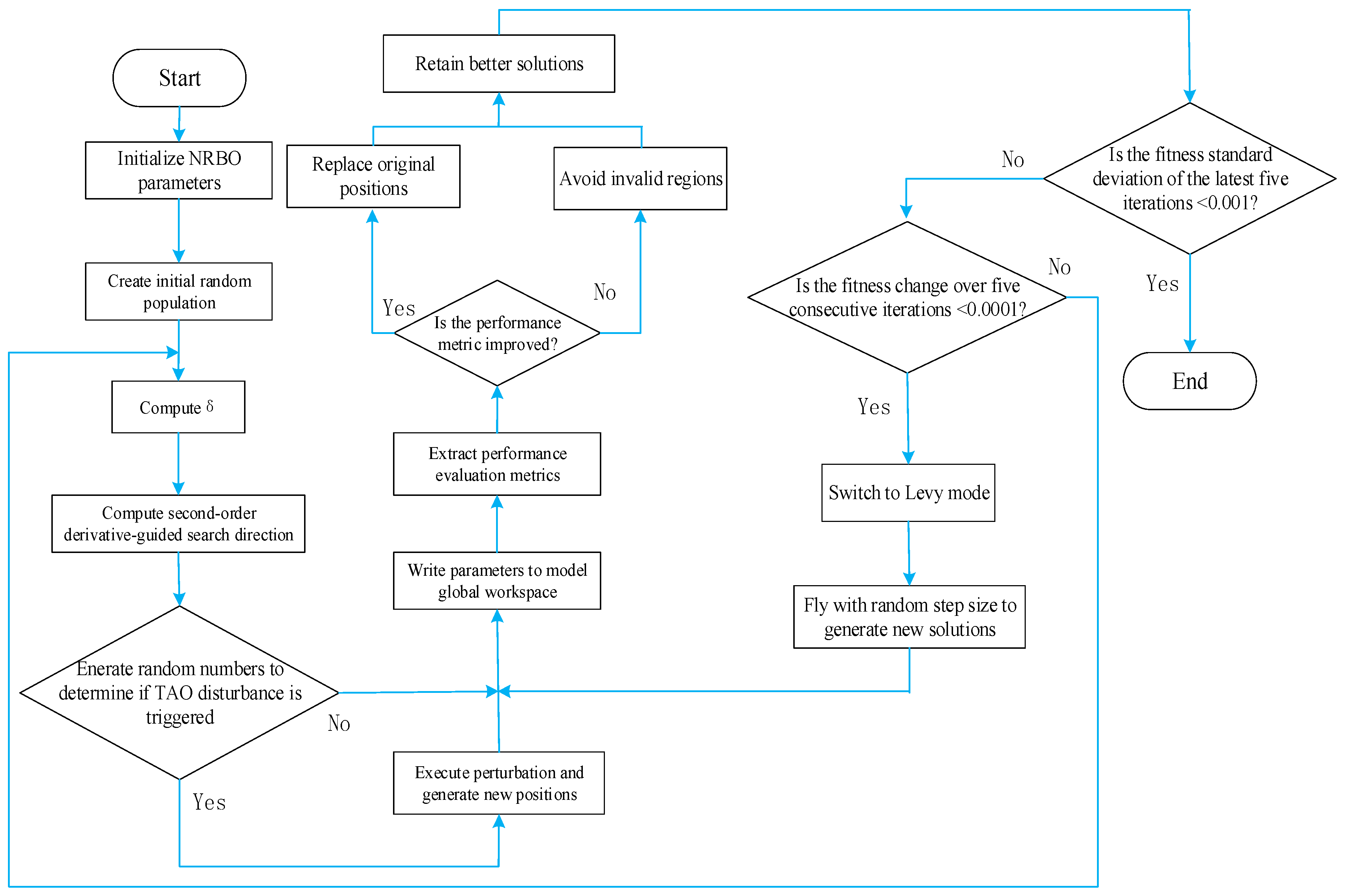
The NRBO is a novel metaheuristic optimization algorithm combining the Newton-Raphson method with swarm intelligence, specifically designed for continuous optimization problems. It simulates natural resource allocation mechanisms and incorporates two core strategies: the Newton-Raphson search rule (NRSR) and the trap avoidance operator (TAO), balancing global exploration and local exploitation. The algorithm flowchart is shown in Figure 5.
In NRBO, each candidate solution is abstracted as an “individual” in the population, represented by a position vector X i = x 1 i , x 2 i , , x D i , where D denotes the problem dimension (e.g., six tunable parameters in ADRC correspond to D = 6 ). During initialization, individual positions are randomly generated within the search space following a uniform distribution rule:
x j n = l b j + rand × ( u b j l b j )
where l b j   and u b j   are the lower and upper bounds of the j -th dimensional variable.
During iteration, the NRSR accelerates local convergence by leveraging second-order derivative information. Each individual updates its position based on the difference between the neighborhood’s best solution X b and worst solution X w :
Δ x = rand ( 1 , D ) × X b X n i t
where rand 1 , D generates a D -dimensional random perturbation to ensure search diversity. The Newton iteration formula generates new positions, while regularization corrects the Hessian matrix’s non-positive definiteness, enhancing numerical stability.
To avoid local optima, the TAO combines the best position X b and current vector position X n i t using random gains to produce higher-quality X T A O i t . A dynamic parameter δ adjusts perturbation intensity to balance diversity and convergence:
δ = 1 2 × i t Max _ i t 5
where i t is the current iteration count Max _ i t and is the maximum iterations. Through the automatic modulation of δ in the iterative process, the diversity and aggregation can be better balanced.
The expression for X T A O i t is defined as:
X T A O i t = X n i t + 1 + θ 1 × μ 1 × x b μ 2 × X n i t + θ 2 × δ × μ 1 × Mean ( X i t ) μ 2 × X n i t , μ 1 < 0.5 X T A O i t = x b + θ 1 × μ 1 × x b μ 2 × X n i t + θ 2 × δ × μ 1 × Mean ( X i t ) μ 2 × X n i t , μ 1 0.5
where θ 1 and θ 2 are random numbers within intervals ( 1 , 1 ) and ( 0.5 , 0.5 ) , respectively, providing stochastic perturbations, while μ 1 and μ 2 are random weights for balancing the optimal solution and population mean.
By efficiently utilizing second-order derivative information, NRBO significantly improves convergence speed and precision, particularly for high-dimensional nonlinear optimization. In this study, NRBO optimizes six ADRC parameters to achieve optimal control performance while reducing manual tuning efforts. To evaluate controller parameters, a modified ITAE performance index is adopted, tailored for position control applications (e.g., high-precision industrial cutting). Unlike traditional ITAE, this variant penalizes positive errors (overshoot) more severely than negative errors, as overshoot is often intolerable in practice, while negative errors can be corrected through reoperation. The performance index is formulated as:
2 0 T t e ( t ) d t , e ( t ) 0 0 T t e ( t ) d t , e ( t ) < 0
where T is the total operation time, and e ( t ) is the position tracking error. Smaller ITAE values indicate faster response, higher precision, and reduced overshoot, enabling NRBO to identify optimal ADRC parameters for specific working conditions. The optimized PMSM position control system structure is illustrated in Figure 6. The position reference θ and actual position θ are compared, and their error is fed into the NRBO_ADRC module for performance evaluation. The NRBO continuously searches for parameters minimizing the ITAE value, with the optimal set written to the workspace for real-time control.

4. Simulation Experiments and Result Analysis

To validate the effectiveness of the proposed MADRC and Newton-Raphson-based optimizer (NRBO) in enhancing PMSM position control performance, a simulation platform is established in MATLAB2023a/Simulink based on Figure 6. Six control strategies are compared:
(1)
ADRC: Conventional active disturbance rejection controller.
(2)
F_ADRC: ADRC with optimized nonlinear function.
(3)
MADRC: F_ADRC with delay compensation module.
(4)
NRBO-MADRC: MADRC with NRBO-based parameter auto-tuning.
(5)
PSO_PID: PID optimized by particle swarm optimization.
(6)
MSMC (modified sliding mode controller): The original exponential convergence law s . = ε sign ( s ) q s of the sliding mode controller has been modified to the following form s . = ε x 1 2 + x 2 2 tan h ( s ) q s x 1 α , thereby achieving better anti-interference performance and response speed.
In the above equation, Improving the parameters of the sliding mode controller x 1 and x 2 are the state variables of the PMSM: x 1 = θ θ x 2 = x 1 . = θ ˙ θ ˙ , Among them, θ represents the Reference the given position, while θ represents the actual position. Parameters for ADRC, F_ADRC, and MADRC are tuned via bandwidth methods (see Equation (25)), while NRBO-MADRC and PSO_PID parameters are algorithmically optimized. Comparative simulations under loaded conditions demonstrate the superiority of NRBO-MADRC.

4.1. Sinusoidal Signal Tracking Under Load

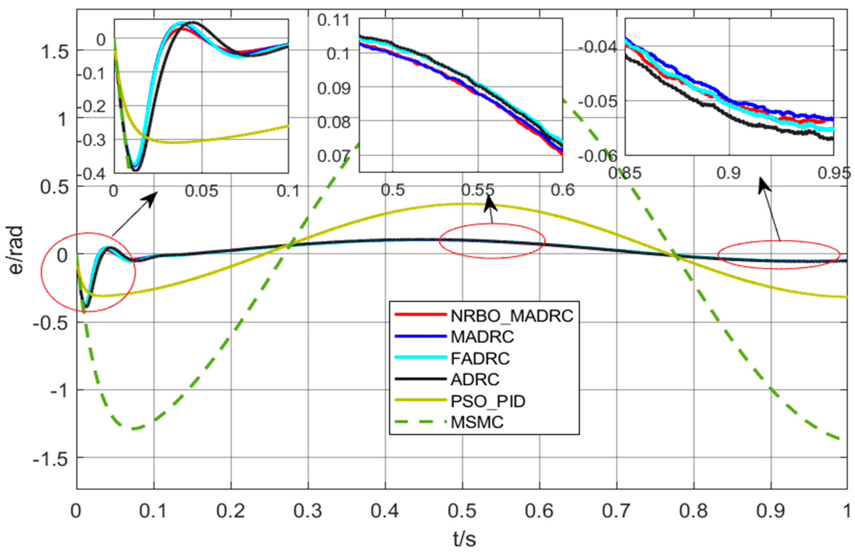
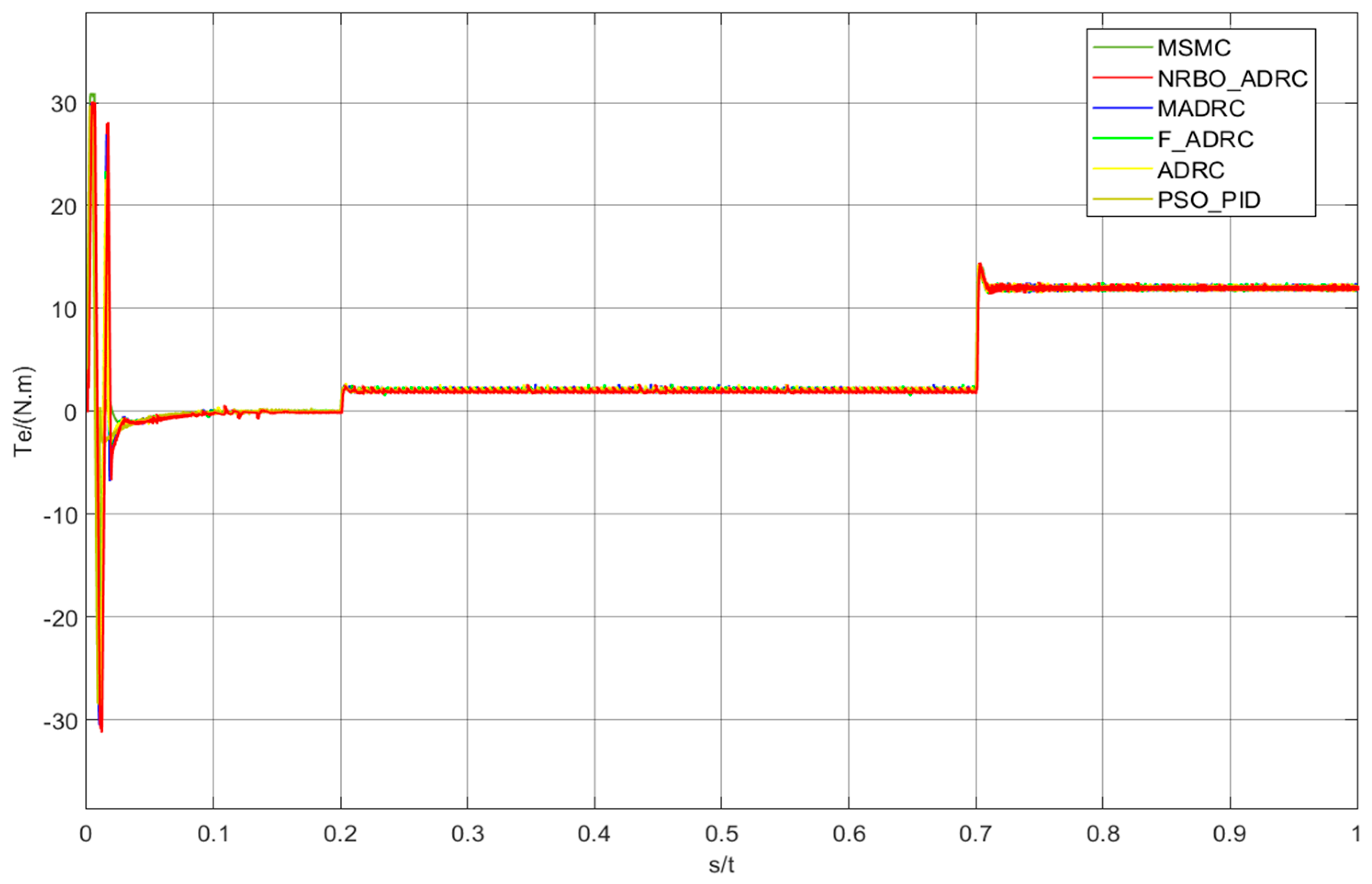
This experiment verifies the tracking performance for the given signal θ = 8 sin ( π t ) under step load disturbance. Simulation results are shown in Figure 7 and Figure 8, respectively.
According to the simulation results, the curve of MSMC is smoother, but both its response speed and tracking accuracy are poorer, PSO_PID exhibited faster startup and smaller torque ripple, but its overall error was significantly larger compared to other control methods. ADRC showed the most pronounced torque ripple and chattering, which should be attributed to the non-smooth nonlinear function. Overall, NRBO_MADRC outperformed other control methods. However, subtle differences were difficult to discern visually. Therefore, the total error was quantified by integrating the absolute difference between the position output and the reference value. The integrated absolute position errors for MSMC, PSO_PID, ADRC, F_ADRC, MADRC, and NRBO-MADRC were measured as 0.8711, 0.2167, 0.06022, 0.05823, 0.05728, and 0.05717, respectively. These data confirm the effectiveness of the designed position control system, with the NRBO_MADRC-based system demonstrating excellent tracking performance. Although the position error curve in Figure 7 exhibits positive values, these errors are mainly caused by phase errors. Due to the fact that the system output lags behind the reference, the output response is slower than the reference, which leads to positive position errors when the reference signal changes from large to small. Moreover, the overshoot in the initial stage can also be reduced or eliminated by adjusting the controller parameters.

4.2. Variable-Load Experiment Under Step Signal

This experiment verifies the tracking performance for the given step position signal θ = 4 ( t ) under variable load disturbance. A step signal was selected as the reference for analysis, with load changes applied at 0.2 s (light load) and 0.7 s (heavy load). The results are shown in Figure 9 and Figure 10.
According to the simulation results, under variable load conditions with a step signal, the torque and position of each control system are similar. However, by magnifying the position error graph, it can be observed that the settling time of PSO_PID is significantly longer than that of other controllers. This is due to the large penalty coefficient applied to the overshoot during PSO optimization to avoid overshooting. Additionally, its steady-state error is larger compared to other types of ADRC control systems. The steady-state error of MSMC is very small, but its anti-disturbance performance is still significantly inferior to that of ADRC and PSO-PID control, and the corresponding regulation time is also longer. Since ADRC inherently possesses strong disturbance rejection performance, the disturbance rejection capabilities of all control methods are similar when a light load is applied at 0.2 s. However, when a heavy load is applied at 0.7 s, NRBO_MADRC and MADRC are relatively less affected by the disturbance, demonstrating stronger disturbance rejection performance. This proves that the NRBO_MADRC-based position control system designed in this study exhibits excellent disturbance rejection performance. As can be seen from Figure 9, when the position reference is a step signal, there is a small overshoot in the initial stage; this overshoot can be reduced or eliminated by adjusting the controller parameters, thereby meeting the performance requirements in the position overshoot-free field.

4.3. No-Load Experiment Under Square Wave Signal

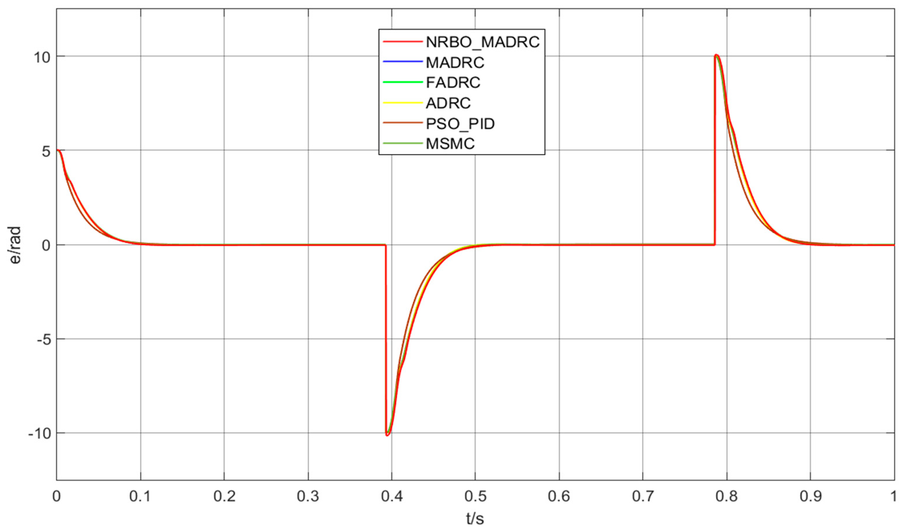
This experiment verifies the tracking performance for the given square wave signal θ = 5 sign ( sin ( 8 t π / 2 ) ) under no-load disturbance. The results are shown in Figure 11 and Figure 12, respectively.
According to the simulation results, under no-load conditions with a square wave signal, the control performance of each system is generally similar. By magnifying the position error graph, it can be observed that, similar to the step signal, the settling time of PSO_PID is significantly longer than that of other controllers, and its steady-state error is larger. Except for the notably larger position error of PSO_PID, the position errors under other control methods are close and difficult to accurately distinguish from the graph. Therefore, this study quantifies the total error by taking the absolute value of the difference between the position output and the given value and then integrating it. The integrated absolute position errors for MSMC, PSO_PID, ADRC, F_ADRC, MADRC, and NRBO-MADRC are measured as 0.7926, 0.7985, 0.795, 0.7946, 0.7933, and 0.7858, respectively. In the case of a loadless square wave, the performance of MSMC is excellent and is similar to that of the ADRC without parameter tuning. However, it is still significantly inferior to the MADRC with tuned parameters of NRBO. This demonstrates that the NRBO-MADRC-based position control system designed in this study exhibits excellent disturbance rejection performance. Positive position errors appear in Figure 11; the reason is that when the reference θ = 5 sign ( sin ( 8 t π / 2 ) ) is −5 at t = 0 , the system output is 0, thus resulting in a position error with an amplitude of 5.

4.4. Prototype Experiment

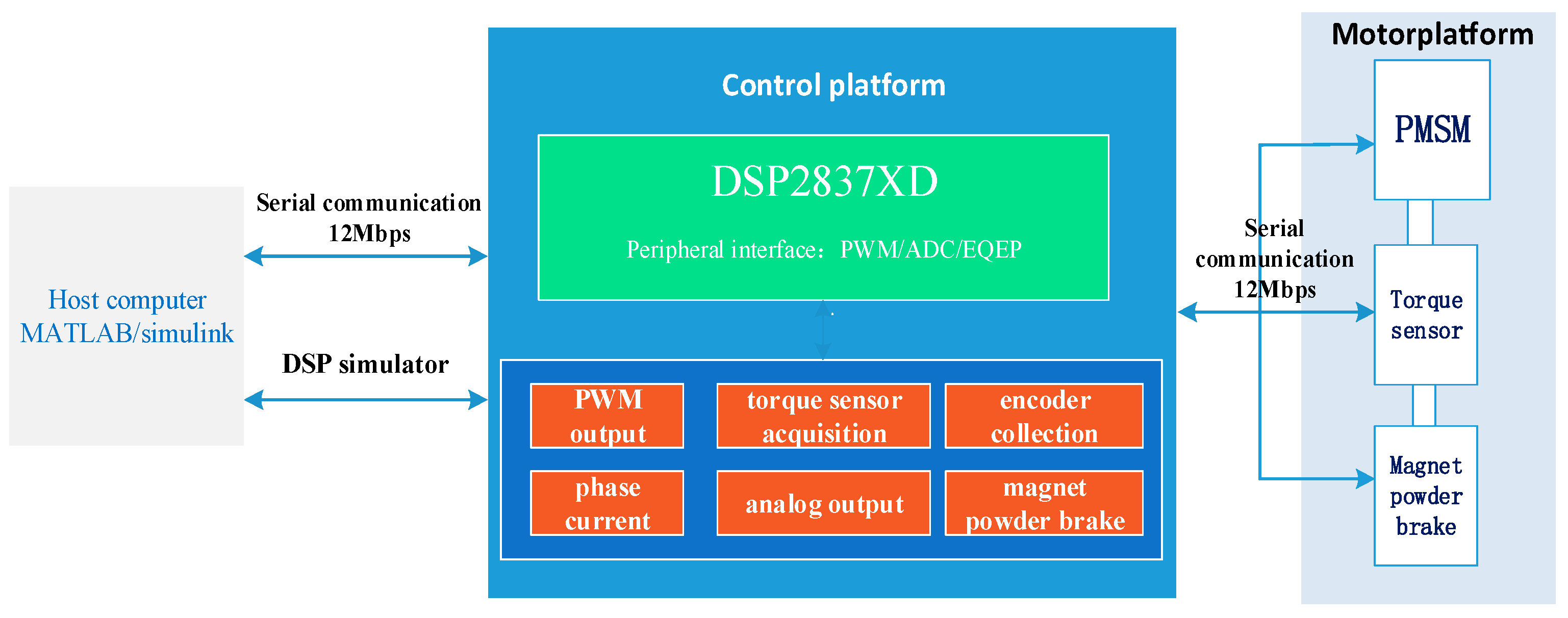
In order to verify the applicability of the control algorithm proposed in this paper, a PMSM control platform with DSP as the core is built. The system structure block diagram is shown in Figure 13, which is mainly divided into a host computer, a control platform, and a motor platform.
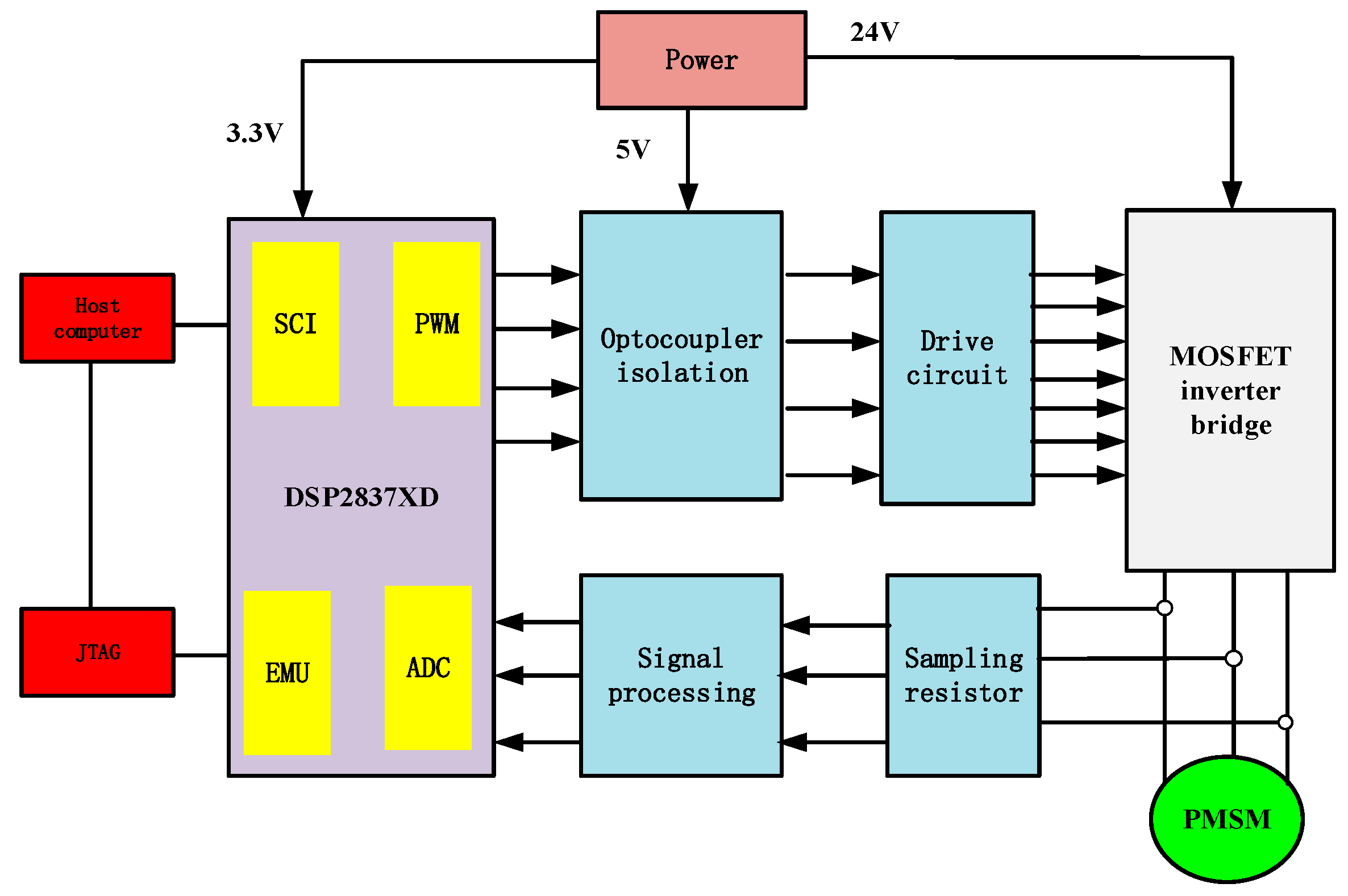
The control platform includes a MOSFET inverter bridge depicted in Figure 14, a gate drive, a sampling resistor, DSP2837XD, and so on. The motor platform mainly includes a servo motor, a torque sensor, and a magnetic powder brake.
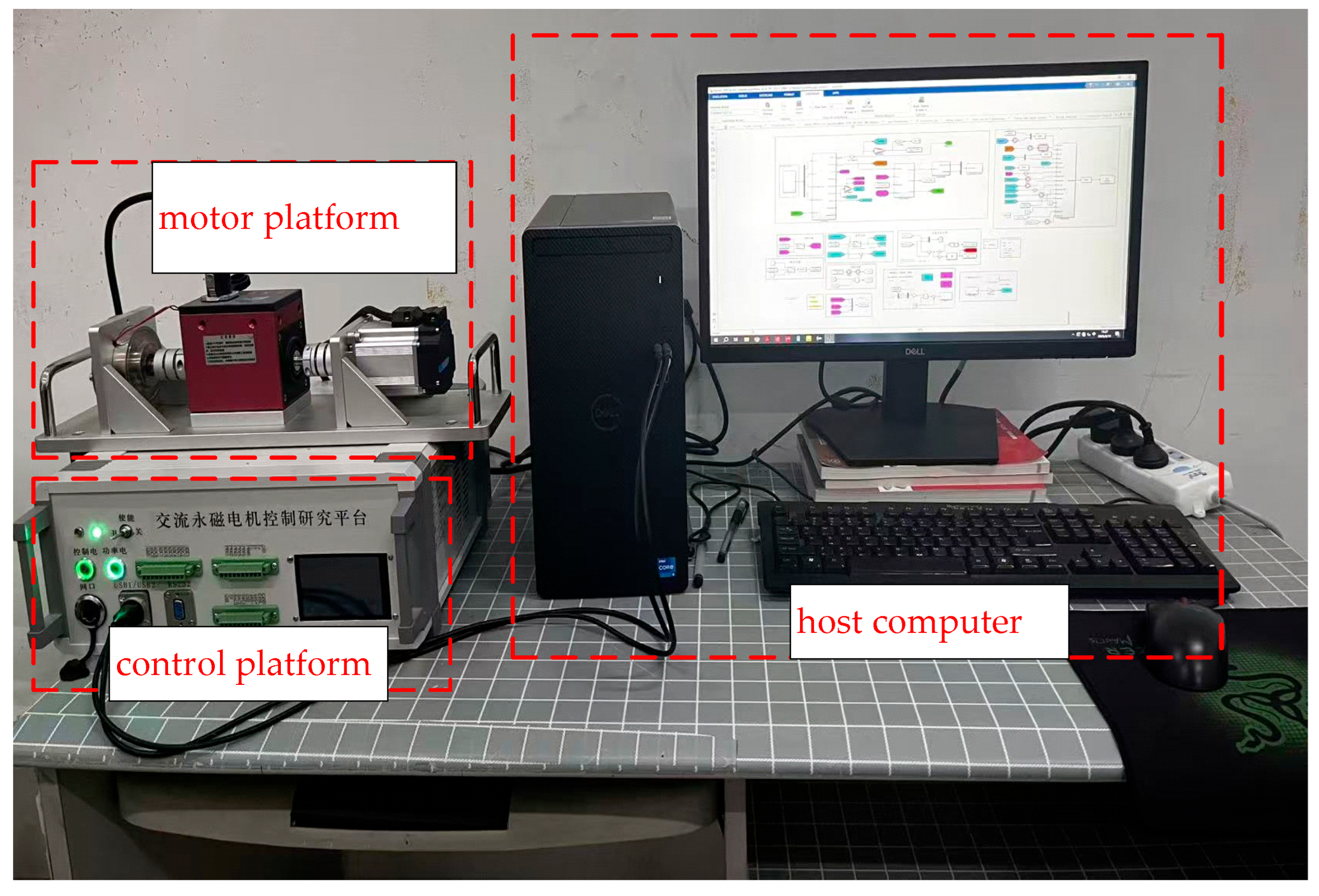
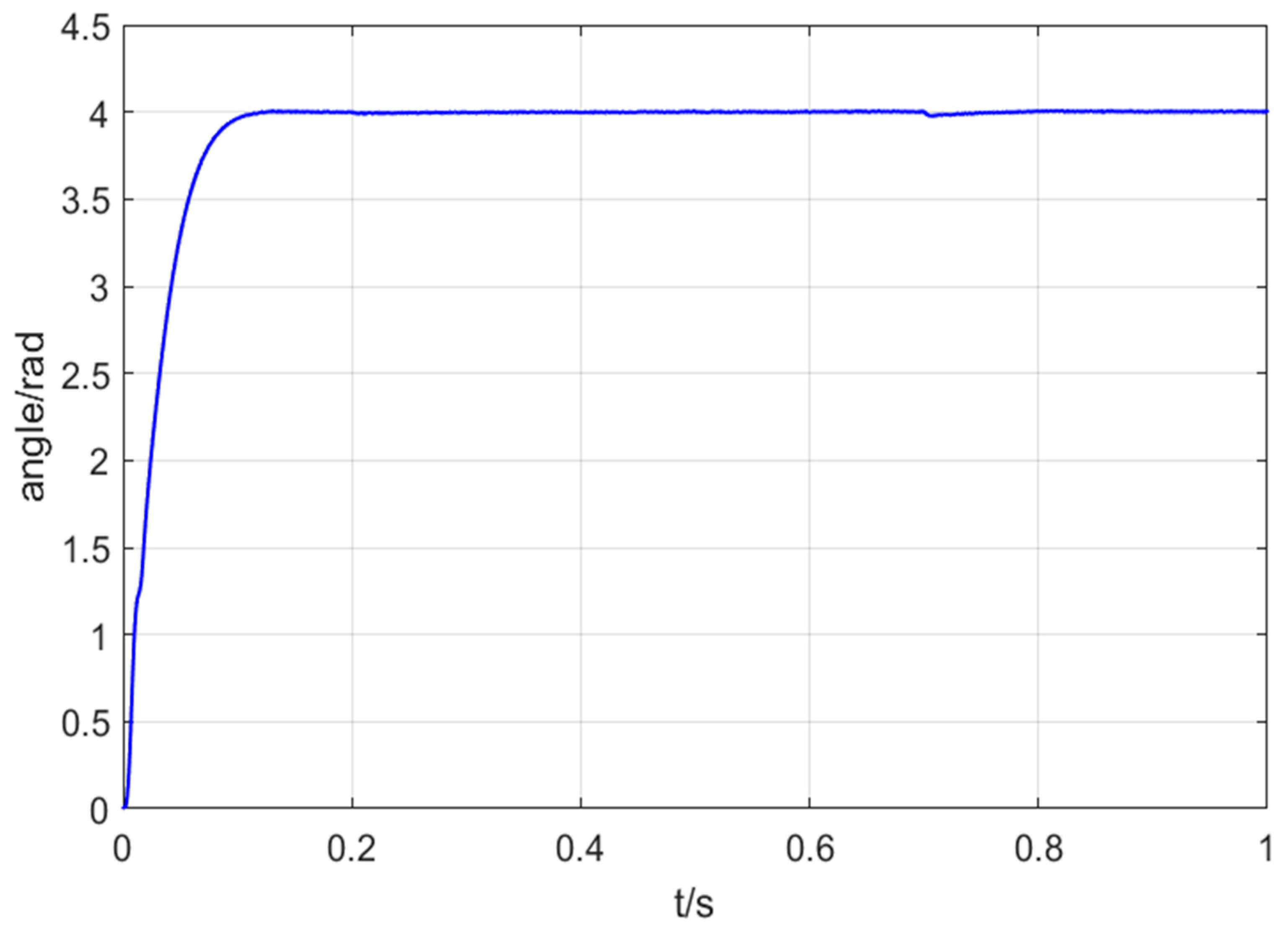
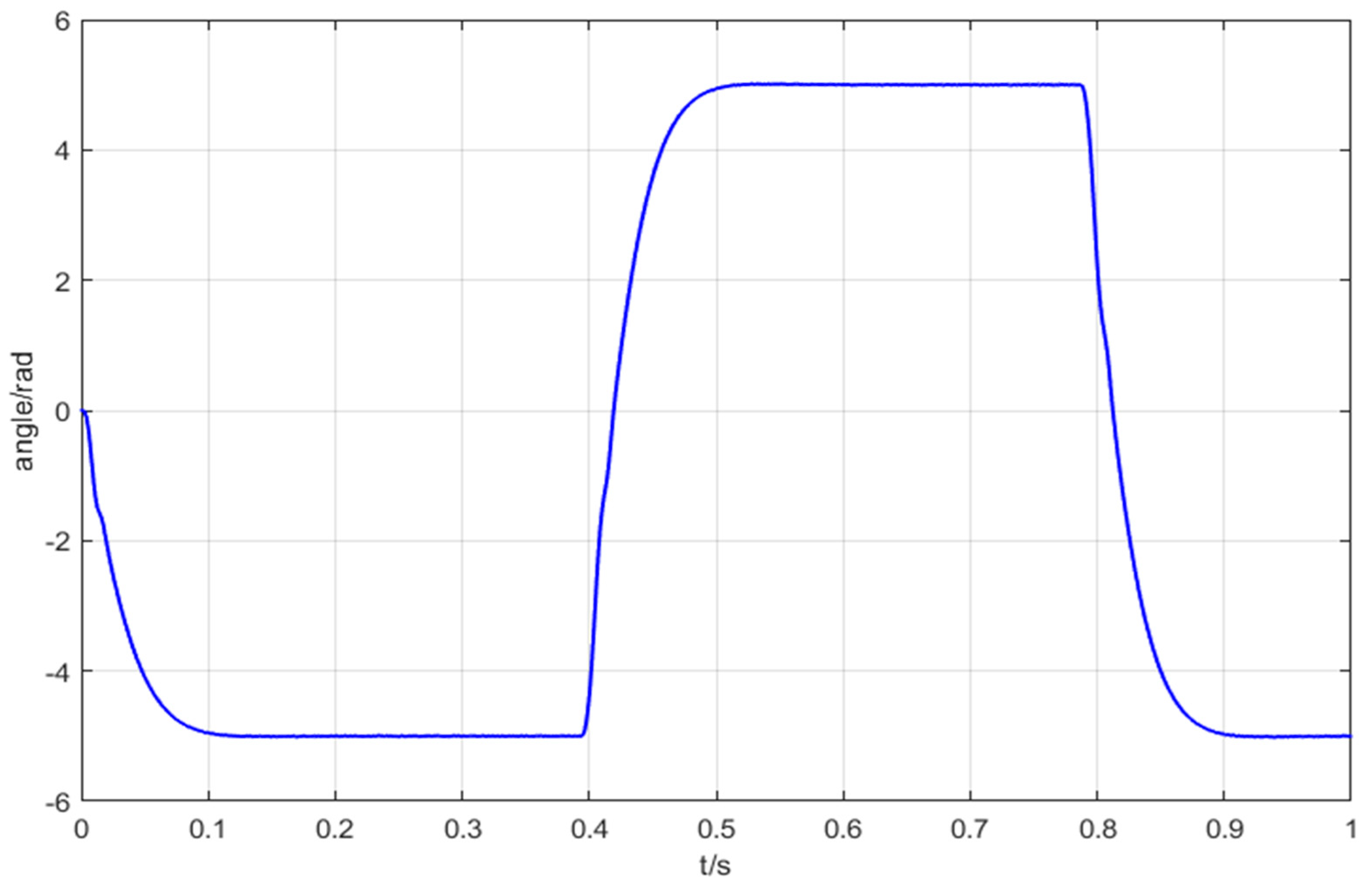
The experimental platform of the PMSM control system is shown in Figure 15. Since the position reference of the experimental device adopts a numerical method (instead of a potentiometer-based reference), experiments on step position reference and square wave position reference were conducted, respectively, using the control strategy proposed in this paper. Figure 16 presents the experimental curve of the step position reference tracking response, and Figure 17 presents the experimental curve of the square wave position reference tracking response.
As can be seen from the experimental results in Figure 16 and Figure 17, the tracking response time is t = 0.12 s , and the steady-state error is e s = 0 . The control strategy proposed in this paper can track the reference signal quickly, accurately and without overshoot, which meets the performance requirements of position control systems.

5. Conclusions

The control strategy studied in this paper is based on an integer-order model, while the actual system exhibits a fractional-order nature; thus, future research needs to focus on fractional-order models and control strategies for fractional-order systems. Additionally, in practical applications, it is also necessary to consider how to suppress noise disturbances. This paper designed a position control system for PMSMs. To further improve the precision, response speed, and disturbance rejection capability of PMSM position control, the nonlinear functions in the ESO and NLSEF of the ADRC were optimized; additionally, a compensation module was added before the output of the ADRC enters the ESO to synchronize the two input signals of the ESO (i.e., the control quantity and system output quantity). Moreover, a parameter self-tuning method for ADRC based on the NRBO was implemented. Through numerical simulations and comparison of the experimental results, the integral of error of the control strategy proposed in this paper is 94% of that of the traditional ADRC, the maximum error is 95% of that of the traditional ADRC, and the adjustment time is 86% of that of the traditional ADRC. The following conclusions are drawn:
(1)
The improved ADRC-based PMSM position control design can meet high-performance requirements under complex working conditions, thus achieving fast response, minimal overshoot, and strong disturbance rejection capability.
(2)
The ADRC parameter self-tuning based on the NRBO eliminates the need for manual parameter adjustment, reduces implementation complexity, improves tuning accuracy, and further enhances the overall control performance of the ADRC.
The control strategy proposed in this paper is based on an integer-order model, while the actual system exhibits fractional-order nature; thus, future research should focus on fractional-order models and control strategies applied to fractional-order systems. Additionally, in practical applications, consideration should also be given to how to suppress noise disturbances.

Author Contributions

Conceptualization, Y.X.; Methodology, Y.X. and Z.H.; Software, Z.H. and D.L.; Validation, Y.X. and D.L.; Writing—original draft, Y.X. and Z.H.; Writing—review and editing, D.L. All authors have read and agreed to the published version of the manuscript.

Funding

This work was supported by Science and Technology Research Project of the Education Department of Jilin Province (grants 2015148 and JJKH20240084KJ) and Jilin Provincial Department of Science and Technology (grant 20230204093YY).

Data Availability Statement

Data are contained within the article.

Conflicts of Interest

The authors declare no conflicts of interest.

References

  1. Yang, T.; Yang, M.; Wang, G. Sensorless full-speed domain control of permanent magnet synchronous motors based on pulse frequency injection and fuzzy super-spiral sliding mode observer. Power Tools 2024, 4, 6–13. [Google Scholar]
  2. Sun, Y.; Ming, Y.; Wang, B.; Cheng, Y.; Xu, D. Precise position control based on resonant controller and second-order sliding mode observer for PMSM-driven feed servosystem. IEEE. Trans. Transp. Electrif. 2022, 9, 196–209. [Google Scholar] [CrossRef]
  3. Ma, W.; Yu, H.; Li, W.; Meng, F.; Liu, X.; Yao, M. FMSS improved sliding mode control strategy based on feedback exact linearization decoupling. Electr. Power Eng. Technol. 2023, 42, 92–101. [Google Scholar]
  4. Zhang, R.; Wang, R.; Shi, P.; Ou, H.; Xu, Y.; Wang, S. New adaptive sliding mode and parameter identification control for permanent magnet synchronous motors. J. Electr. Power Syst. Autom. 2025, 1–10. [Google Scholar] [CrossRef]
  5. Song, H.; Wang, S. Sliding mode control of permanent magnet synchronous motor based on second-order low-pass filtering. Coal Mine Mach. 2013, 34, 88–89. [Google Scholar]
  6. Qureshi, I.; Sharma, V. Analysis of different control schemes of PMSM motor and also a comparison of FOPI and PI controller for sensorless MSVPWMM scheme. e-Prime—Advances in Electrical Engineering. Electron. Energy 2023, 6, 100359. [Google Scholar]
  7. Luan, M.; Ruan, J.; Zhang, Y.; Yan, H.; Wang, L. An improved adaptive finite-time super-twisting sliding mode observer for sensorless control of permanent magnet synchronous motors. Actuators 2024, 13, 395. [Google Scholar] [CrossRef]
  8. Sumantri, B.; Uchiyama, N.; Sano, S. Generalized super-twisting sliding mode control with a nonlinear sliding surface for robust and energy-efficient controller of a quad-rotor helicopter. Proc. Inst. Mech. Eng. Part C J. Mech. Eng. Sci. 2017, 231, 2042–2053. [Google Scholar] [CrossRef]
  9. Song, C.; Liu, D.; Ren, L.; Han, J.; Jin, Y.; Cheng, Y.; Li, X.; Zhang, H. Research on speed sensorless control strategy of permanent magnet synchronous motor based on fuzzy super-twisting sliding mode observer. Sci. Prog. 2024, 107, 368504241228106. [Google Scholar] [CrossRef]
  10. Dong, H.; Yang, X.; Gao, H.; Yu, X. Practical terminal sliding mode control and its applications in servo systems. IEEE Trans. Ind. Electron. 2023, 70, 752–761. [Google Scholar] [CrossRef]
  11. Fu, D.; Zhao, X. A novel robust adaptive nonsingular fast integral terminal sliding mode controller for permanent magnet linear synchronous motors. IEEE J. Emerg. Sel. Top. Power Electron. 2023, 11, 1672–1683. [Google Scholar] [CrossRef]
  12. Wang, Z.; Wen, C.; Zhu, C.; Zhang, Z.; Yu, K.; Cheng, M. Deadbeat Predictive Control for Position Servo Permanent Magnet Motor. Trans. China Electrotech. Soc. 2023, 38, 5176–5184. [Google Scholar]
  13. Zhang, K.; Wang, L. Adaptive sliding mode position control for permanent magnet linear motor based on periodic disturbance learning. J. Electr. Mach. Control. 2021, 25, 132–141. [Google Scholar]
  14. Zhou, D.; Wang, B.; Ai, B.; Zhang, W.; Gao, Y. Nonlinear active disturbance rejection control of hydraulic turbine regulating system considering dead zone. J. Hydroelectr. Eng. 2023, 42, 114–127. [Google Scholar]
  15. Paek, S.-Y.; Kong, Y.-S.; Pak, S.-H.; Kang, J.-S.; Yun, J.-N.; Kil, H.-I.; Hwang, C.-J. Robust optimal tuning of a reduced active disturbance rejection controller based on first-order plus dead time model approximation. Eng. Appl. Artif. Intell. 2024, 133, 108338. [Google Scholar] [CrossRef]
  16. Liu, D.; Han, J.; Chen, G.; Cheng, Y.; Song, C. Fuzzy self-tuning fractional order PD permanent magnet synchronous motor speed control based on torque compensation. Sci. Rep. 2025, 15, 2141. [Google Scholar] [CrossRef]
  17. Zhao, K.; Jia, N.; She, J.; Dai, W.; Zhou, R.; Liu, W.; Li, X. Robust model-free super-twisting sliding mode control method based on extended sliding mode disturbance observer for PMSM drive system. Control. Eng. Pract. 2023, 139, 105657. [Google Scholar] [CrossRef]
  18. Rabiee, H.; Ataei, M.; Ekramian, M. Continuous nonsingular terminal sliding mode control based on adaptive sliding mode disturbance observer for uncertain nonlinear systems. Automatics 2019, 109, 108515. [Google Scholar] [CrossRef]
  19. Jun, Y.; Chen, W.-H.; Li, S.; Guo, L.; Yang, Y. Disturbance/Uncertainty Estimation and Attenuation Techniques in PMSM Drives—A Survey. IEEE Trans. Ind. Electron. 2016, 64, 3273–3285. [Google Scholar]
  20. Han, J. Using Sign Function and Absolute Function to Construct Nonlinear Function. Control. Eng. China 2008, S2, 4–6. [Google Scholar]
  21. Han, J. Nonlinear State Error Feedback Control Law—NLSEF. Control. Decis. 1995, 03, 221–225. [Google Scholar]
  22. Han, J. The “Extended State Observer” of a Class of Uncertain Systems. Control. Decis. 1995, 1, 85–88. [Google Scholar]
  23. Han, J.; Zhang, R. Error analysis of second-order expansion state observer. Syst. Sci. Math. 1999, 4, 465–471. [Google Scholar]
  24. Zhang, J.; Yang, Z.; Qi, G.; Liu, G. Improved Active Disturbance Rejection Control of Permanent Magnet Synchronous Motor. Power Electron. 2024, 58, 30–33. [Google Scholar]
  25. Fang, S.; Fan, J. A Composite Control Strategy of Permanent Magnet Synchronous Motor Based on Active Disturbance Rejection. Electr. Mach. Control. Appl. 2023, 50, 62–69. [Google Scholar]
  26. Du, B.; Wu, S.; Han, S.; Cui, S. Application of Linear Active Disturbance Rejection Controller for Sensorless Control of Internal Permanent-Magnet Synchronous Motor. IEEE Trans. Ind. Electron. 2016, 63, 3019–3027. [Google Scholar] [CrossRef]
  27. Qu, L.; Qiao, W.; Qu, L. An Enhanced Linear Active Disturbance Rejection Rotor Position Sensorless Control for Permanent Magnet Synchronous Motors. IEEE Trans. Power Electron. 2020, 35, 6175–6184. [Google Scholar] [CrossRef]
  28. Cai, G.; Zhou, X.; Liu, X. Auto Disturbance Rejection Tracking Control of Electro-hydraulic Position Servo System Optimized by Improved PSO Algorithm. Mech. Sci. Technol. Aerosp. Eng. 2021, 40, 1904–1912. [Google Scholar]
  29. Li, L. ADRC controller optimization design based on improved PSO algorithm for attitude control of helicopter. Inf. Commun. 2019, 4, 44–48. [Google Scholar]
  30. Wang, L.; Xu, C.; Ju, Y.; Liu, G. Nonlinear auto disturbance rejection control via the improved shark smell optimization for permanent magnet synchronous motor. Chin. J. Sci. Instrum. 2023, 44, 303–312. [Google Scholar]
  31. Sowmya, R.; Premkumar, M.; Jangir, P. Newton-Raphson-based optimizer: A new population-based metaheuristic algo-rithm for continuous optimization problems. Eng. Appl. Artif. Intell. 2024, 128, 107532. [Google Scholar] [CrossRef]
  32. Sun, H.; Madonski, R.; Li, S.; Zhang, Y.; Xue, W. Composite Control Design for Systems With Uncertainties and Noise Using Combined Extended State Observer and Kalman Filter. IEEE Trans. Ind. Electron. 2021, 69, 4119–4128. [Google Scholar] [CrossRef]
  33. Niu, Z. Enhanced ADRC Position Servo System Based on Fourth-Order ESO. Master’s Thesis, Jiangsu University, Zhenjiang, China, 2023. [Google Scholar]
  34. Shen, W.; Ran, Q.; Zhao, S. Vector Control of Permanent Magnet Synchronous Motor Based on Auto Disturbance Rejection and Improved ESO. Modul. Mach. Tool Autom. Manuf. Tech. 2023, 9, 77–81. [Google Scholar]
  35. Cheng, S.; Liu, X.; Wang, C.; Zhou, R.; Xiang, C. Synchronous Control of High-Speed Train Lift Wing Angle of Attack Drive System Based on Active Disturbance Rejection. Electr. Mach. Control. Appl. 2023, 50, 1–7. [Google Scholar]
  36. Liu, X.; Chai, Q. Research on the Vector Control Strategy of PMSM Based on ADRC + Advanced Repeat Control. Power Electron. 2020, 54, 1–5. [Google Scholar]
  37. He, D.; Lin, H.; Liu, L.; Chen, J.; Zeng, Z.; Wang, P. Improved Nonlinear Backstepping Active Disturbance Rejection Position Control for Permanent Magnet Synchronous Motor. Modul. Mach. Tool Autom. Manuf. Tech. 2023, 7, 73–78. [Google Scholar]
Figure 1. Structure diagram of second-order ADRC.
Applsci 15 10467 g001
Figure 2. Gain comparison of nonlinear functions.
Applsci 15 10467 g002
Figure 3. Comparison of nonlinear functions curves.
Applsci 15 10467 g003
Figure 4. Schematic of MADRC for high-order systems.
Applsci 15 10467 g004
Figure 5. Flowchart of Newton-Raphson-based optimizer.
Applsci 15 10467 g005
Figure 6. Overall structure of the PMSM position control system.
Applsci 15 10467 g006
Figure 7. Position tracking error under sinusoidal input.
Applsci 15 10467 g007
Figure 8. Torque output under sinusoidal input.
Applsci 15 10467 g008
Figure 9. Position error under step signal.
Applsci 15 10467 g009
Figure 10. Torque output under step signal.
Applsci 15 10467 g010
Figure 11. Position error under square wave signal.
Applsci 15 10467 g011
Figure 12. Torque output under square wave signal.
Applsci 15 10467 g012
Figure 13. System structure diagram.
Applsci 15 10467 g013
Figure 14. Control platform structure diagram.
Applsci 15 10467 g014
Figure 15. Experimental platform of the PMSM control system.
Applsci 15 10467 g015
Figure 16. Step position tracking response curve.
Applsci 15 10467 g016
Figure 17. Square wave position tracking response curve.
Applsci 15 10467 g017
Disclaimer/Publisher’s Note: The statements, opinions and data contained in all publications are solely those of the individual author(s) and contributor(s) and not of MDPI and/or the editor(s). MDPI and/or the editor(s) disclaim responsibility for any injury to people or property resulting from any ideas, methods, instructions or products referred to in the content.