Article

GPU-Driven Acceleration of Wavelet-Based Autofocus for Practical Applications in Digital Imaging

Human-Centric Manufacturing Technology, KITECH, Ansan 15588, Republic of Korea
*
Author to whom correspondence should be addressed.
Appl. Sci. 2025, 15(19), 10455; https://doi.org/10.3390/app151910455
Submission received: 10 August 2025 / Revised: 15 September 2025 / Accepted: 22 September 2025 / Published: 26 September 2025
(This article belongs to the Special Issue Data Structures for Graphics Processing Units (GPUs))

Abstract

A parallel implementation of wavelet-based autofocus (WBA) was presented to accelerate recursive operations and reduce computational costs. WBA evaluates digital focus indices (DFIs) using first- or second-order moments of the wavelet coefficients in high-frequency subbands. WBA is generally accurate and reliable; however, its computational cost is high owing to biorthogonal decomposition. Thus, this study parallelized the Daubechies-6 wavelet and norms of the high-frequency subbands for the DFI. The kernels of the DFI computation were constructed using open sources for driving multicore processors (MCPs) and general processing units (GPUs). The standard C++, OpenCV, OpenMP, OpenCL, and CUDA open-source platforms were selected to construct the DFI kernels, considering hardware compatibility. The experiment was conducted using the MCP, peripheral GPUs, and CPU-resident GPUs on desktops for advanced users and compact devices for industrial applications. The results demonstrated that the GPUs provided sufficient performance to achieve WBA even when using budget GPUs, indicating that the GPUs are advantageous for practical applications of WBA. This study also implies that although budget GPUs are left unused, they can potentially be great resources for wavelet-based processing.

1. Introduction

Discrete wavelet transformation (DWT) has contributed to opening new horizons in computer vision and image processing. DWT applications have widened to include denoising [1], enhancement [2], compression [3], recognition [4], and depth maps [5]. DWT can enhance the signal quality and edges in an image by separating high-frequency subbands; thus, wavelet-based autofocus (WBA) has been developed based on these characteristics. In previous studies, wavelets were applied to enhance edges before focusing. Widjaja proposed autocorrelation-based autofocus after denoising backlight images using a wavelet and experimentally improved the focal sensitivity [6]. However, in this study, the focus was determined using autocorrelation, and a wavelet was used as an auxiliary method for image quality. An intuitive formulation of WBA was proposed by computing the high-frequency subbands. The L1 norm of a the bidirectional high-frequency subband (HH) was introduced as a focus measure and exhibited more reliable performance than the discrete cosine transform [7]. Similarly, Acharya proposed a focus measure from the absolute average of unidirectional high-frequency subbands (LH and HL) [8].
Wavelet-based focus measures commonly used in current studies originated from focus measures for unsupervised image segmentation (UIS) [9]. UIS is a method for categorizing image pixels into the nearest classes without the intervention of human-generated labels [10,11]. An image comprises objects with different focuses because of the three dimensional shapes on the object’s surface and the limited depth-of-focus in the optical components [12]. Thus, an image can be separated into its respective focal regions by classifying the wavelet coefficients [13]. The focus of a scene is determined by the dominant high-frequency components in an image; thus, subband separation using wavelets have been applied to UIS in numerous studies. Wavelet-based UIS is advantageous for detecting an object of interest and separating the foreground from the background [14]. Thus, wavelet-based UIS has commonly been discussed in the classification of biological tissues [15], internal organs [16], topology analysis [17], and galaxy behavior [18].
Whereas UIS refers to the wavelet coefficients in local images, practical autofocus monitors a focus measure that is evaluated from the wavelet coefficients of the entire image. Kautsky proposed a focus measure using the ratio of wavelet norms between high- and low-frequency subbands. The focus measure was monotonic and reliable for the variable blurring of target images in photography and astronomical imaging [19]. Yang derived a focus measure from the first- and second-order moments of the wavelet transform [20]. It is currently used as a digital focus index (DFI) based on wavelets, and this formulation has been adopted in numerous studies on WBA. The moment-based method presented a significant increase in focus performance in the experiment and is suitable for high-resolution computer vision. The combinations of the absolute and squared norms of the wavelet subbands were explored by Zong [21]. He experimented with a microassembly method for microfluidic chip packaging and demonstrated that WBA enhanced high-frequency information. The norms of the wavelet energy were proposed as a focus measure by Xie. The focus measure was obtained from the squared ratio of the sums of the subbands [22]. Makkapati reported that the WBA is smooth, undulating, and accurate when red blood cells are inspected by microscopy [23]. Akiyama explored autofocus using a Daubechies wavelet, and the focus measure was accurate in applications involving an electric ground vehicle [24]. Advanced wavelet transforms were applied to autofocus and provided high sensitivity and accuracy for true focus [25,26]. The enhanced discrete wavelet transform for autofocus offers stable performance against noise, illumination variation, and feature orientations [27]. Several studies have investigated various wavelet basis functions, including customized wavelet functions for autofocus [28,29]. Genetic algorithms have been utilized alongside the Daubechies 7 wavelet transform to increase the accuracy and sensitivity [30]. The non-subsampled shearlet wave transform improved noise immunity and accuracy in autofocus [31]. As various DFIs are available in practical autofocus, comparative studies on DFIs have become popular with the aim of selecting a prime DFI for various objects and scenes [32,33,34]. In a recent study, WBA was applied to verify autofocus based on artificial intelligence [35].
A wavelet-based DFI (WDFI) is generally robust because it intensifies the details of focused regions based on the statistical coefficients [36]. However, the computation cost for the WDFI is high when decomposing an image into subbands of different frequencies [37]. Because super-resolution image sensors are employed in mobile devices and industrial machine vision [38,39], the computational cost of the WDFI must be overcome because of its superior characteristics. In summary, the WDFI is smooth, accurate, and reliable; however, its computational cost is an obstructive factor for developing practical applications.
High performance processors, such as multicore processors (MCPs) and general processing units (GPUs), have become popular in recent desktops, mobile devices, and consumer electronics; thus, the circumstances for parallel processing have been well constructed. The resolution of current imaging devices has sharply increased; thus, establishing a countermeasure to the computational cost of WBA is crucial. Parallel processing is effective for accelerating gradient- and histogram-based DFIs [40,41]. The parallel implementation of 2D wavelets has been presented in many studies, with several proposing techniques to improve the processing speed of the DWT [42,43,44]. DWT acceleration is a key issue in data compression and image coding for real-time applications [45,46]. Acceleration of 2D DWT for denoising has also been achieved using peripheral GPUs [47]. However, the WDFI involves DWT without downscaling and includes the summation of subbands. Therefore, conventional parallel DWT implementations should be adapted and optimized specifically for WDFI.
Therefore, this study proposes a parallel implementation of WDFIs using MCPs and GPUs. The proposed method combines the conventional parallel implementation of a 2D wavelet with the moments of the wavelet coefficients. The parallel implementation was verified by observing the frame rate of the WDFIs and the image sizes. The sample images were produced according to the image sensor resolution. The WDFI kernels were developed using open-source platforms. We applied outdated and CPU-resident GPUs to test the WDFI kernels in a practical environment.
The remainder of this paper is organized as follows: In Section 2, we review the conventional parallel implementation of the wavelet transform and present WDFI computation by combining the parallel methods. In Section 3, we present the results of experiments using practical computing platforms. In Section 4, we discuss the performance of the proposed implementation. Finally, Section 5 presents the conclusions of this study and the acceleration of the WDFI for practical applications.

2. Materials and Methods

A parallel WDFI can be implemented using conventional parallel DWT and a parallel reduction in the mathematical moment. Thus, we review the conventional parallel DWT and parallel reduction processes. Different strategies for MCPs and GPUs have been established to parallelize WDFIs.

2.1. Parallelizing 2D Wavelets

In previous studies, WDFIs selectively used high-frequency subbands, such as LH, HL, and HH, obtained from the 2D DWT [48]. The filter bank algorithm (FBA) is a fast approximation of the DWT from signal decomposition by convoluting the low- and high-pass filters [42]. The FBA for 2D DWT can be acquired from biorthogonal decomposition to separate subbands from an image [49]. Biorthogonal decomposition can be expressed with convolutions in the horizontal and vertical directions, as follows: [50].
W ( x , y ) = I ( x , y ) F = k = N / 2 N / 2 I ( x k , y ) F ( k ) W ( x , y ) = I ( x , y ) F T = k = N / 2 N / 2 I ( x , y k ) F ( k )
where W denotes the wavelet matrix, I denotes the original image, F denotes the wavelet filter, and N denotes the filter size. The Daubechies wavelet is a generalized formulation of the Haar wavelet, which convolutes image pixels with an N-th-order wavelet base [51]. In this study, Daubechies 6 (DB6) was applied to the wavelet base without downsampling, similar to previous studies on WDFIs [48]. Biorthogonal decomposition begins from the horizontal convolution of the low and high DB6 coefficients as follows:
W L ( x , y ) W H ( x , y ) = I ( x , y ) D 6 L I ( x , y ) D 6 H
where D6 denotes the wavelet base of DB6 and H/L indicates the convolution of low/high coefficients. The subbands of the original image can then be separated using a vertical convolution of the DB6 coefficients.
W L L ( x , y ) W L H ( x , y ) W H L ( x , y ) W H H ( x , y ) = W L ( x , y ) D 6 L T W L ( x , y ) D 6 H T W H ( x , y ) D 6 L T W H ( x , y ) D 6 H T
Thus, the generalized formulation of the subbands using DB6 can be written as follows:
W i ( x , y ) = I ( x , y ) D 6 i W i j ( x , y ) = W i D 6 j T
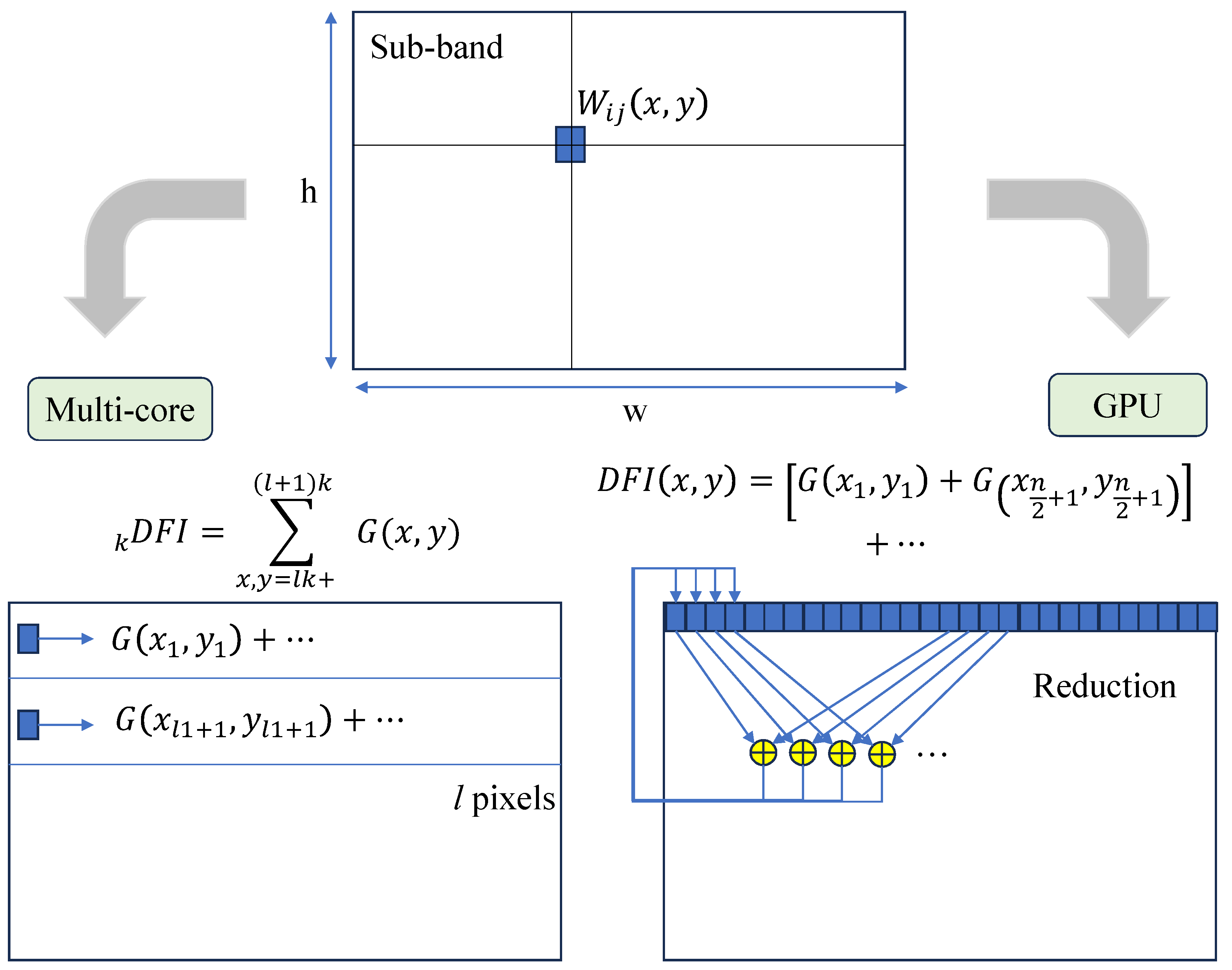
Biorthogonal decomposition is achieved using pixel-based operations and recursive convolutions of DB6, which are the targets of parallelization. By default, a personal computer (PC) is equipped with an MCP and GPU for parallel devices. Data treatment differs in the MCP and GPU; thus, the parallelization strategies are shown in Figure 1. The blue blocks in the figure indicate the pixel data during processing. The MCP comprises few cores with high computational performance; thus, the MCP-based parallel kernel partitions an image into subimages and allocates the biorthogonal decomposition of the subimage into each core [52].
Two-dimensional DWT is conventionally performed on all pixels in an image. Each CPU then sequentially performs a convolution on the pixel data in the allocated subimage. After completing the horizontal decomposition by convolution on all pixels in the subimage, vertical decomposition is performed. The following equation shows the parallel horizontal decomposition of the subimage with a linear transform of the image coordinates:
W i k = z = k l + 1 ( k + 1 ) l I ( x z , y z ) D 6 i W i = k = 1 n W i k
where l denotes the pixel bandwidth for each CPU, and z denotes a linear position in the pixel array in the original image.
W i j k ( x , y ) = z = k l + 1 ( k + 1 ) l W i ( x z , y z ) D 6 j T W i j = k = 1 n W i j k
Parallelization for GPU processing is different from that for the MCP because of data transfer and allocation. Before GPU processing, all pixel data should be transferred to the GPU memory. Subsequently, a thread block grouped by hundreds of arithmetic logic units (ALUs) transforms the thread coordinates into an image and simultaneously synchronizes the horizontal convolution. After completing the convolution in all threads, the thread block moves the processing area according to thread-bandwidth-like scanning. Thus, the thread blocks are linearly transformed into image coordinates using the bandwidth, as follows.
z Z , ( x z , y z ) Z 2 , z = a x z + b y z + c W i k = z = k m + 1 ( k + 1 ) m I ( x z , y z ) D 6 i W i = k = 1 n W i k
where z denotes the thread number, n denotes the number of thread blocks, and m denotes the thread bandwidth. Vertical decomposition is also performed based on horizontal decomposition.
z Z , ( x z , y z ) Z 2 , z = a x z + b y z + c W i j k = z = k m + 1 ( k + 1 ) m W i ( x z , y z ) D 6 j T W i j = k = 1 n W i j k
These wavelet subbands acquired from the parallel processing were applied to calculate the WDFIs, such as the wavelet sum and wavelet variance.

2.2. Wavelet Sum

The wavelet sum is the absolute sum of the wavelet coefficients in high-frequency subbands, such as LH, HL, and HH [7,8]. Yang advanced intuitive studies by deriving the wavelet sum from the first moments of the wavelet coefficients [20]. Zong demonstrated that the Haar wavelet sum was effective for autofocus using experimental approaches and that the squared sums of selective subbands can improve focusing performance [21]. Akiyama applied Daubechies wavelet sum to an electric ground vehicle for high-accuracy filtering [24]. Herrmann introduced Cohen–Daubechies–Feauveau 9/7 coefficients to the wavelet sum in a comparative study on DFI performance [33], which can be defined as the sum of the L1 norms of high-frequency subbands and is expressed as the W1 DFI as follows:
W 1 = y h x w | W L H ( x , y ) | + | W H L ( x , y ) | + | W H H ( x , y ) | = y h x w G ( x , y )
The global sum of G(x,y) is equal to the local sum of the subimages, as described in Equation (5). Thus, each core or ALU simultaneously computes the local sum of G(x,y) for the allocated pixels. For the local sum, the MCP sequentially adds the L1 norms of the high-frequency subbands. In this step, masking operations provided by open sources can be considered before summarizing the results for the pixels of interest in the mask image [53]. Unlike the sequential operations of the MCP, parallel reduction is employed to obtain the sum of a large array of wavelet coefficients [54]. The first reduction performed the addition of two elements to G(x,y) simultaneously [41]. The results of the first reduction are stored in the lower addressed elements, which halve the data array. This addition is performed simultaneously by the ALUs.
W 1 1 ( x , y ) = G ( x , y ) W k + 1 1 ( x z , y z ) = W k 1 ( x z , y z ) W k 1 ( x z + Δ x , y z + Δ y )
The second reduction adds only two elements after the first reduction. The second reduction is iterated by adding two elements and halving the array until the array size reached a single bandwidth. Finally, global sum of the wavelet coefficients is placed at the head of the array. The relationship between the image and the ALU coordinates can be described using the following equation:
z Z , ( x z , y z ) Z 2 , z = a x z + b y z + c a Δ x + b Δ y = Δ z Δ z = m / 2 , m / 4 , , 1 )
Figure 2 explains the parallel sum of the L1 norms of the wavelet coefficients in the subbands using the MCP and GPU. The W1 DFI is the global sum calculated from the local sums after parallel processing.

2.3. Wavelet Variance

The wavelet variance is derived from the second moment of the wavelet coefficients. The W2 WDFI is calculated from the L2 norms of high-frequency subbands [20]. The W2 DFI has been widely used in comparative studies on autofocus [33,48,55].
W 2 = 1 h w y h x w { W L H ( x , y ) μ ¯ L H } 2 + { W H L ( x , y ) μ ¯ H L } 2 + { W H H ( x , y ) μ ¯ H H } 2
where μ ¯ denotes the average of the wavelet coefficients. The simplified formulation in the following equation is advantageous for parallel processing because the sum and squared sum of the wavelet coefficients can be obtained simultaneously.
W 2 = 1 h w y h x w W L H 2 ( x , y ) + W H L 2 ( x , y ) + W H H 2 ( x , y ) ( μ ¯ L H 2 + μ ¯ H L 2 + μ ¯ H H 2 )
The average of wavelet coefficients can be obtained from summing each subband W using parallel processing as follows:
μ ¯ L H , μ ¯ H L , μ ¯ H H = 1 h w y h x w W L H , 1 h w y h x w W H L , 1 h w y h x w W H H
The parallel implementation in Equations (11) and (9) can be reused by redefining G(x,y). The operations necessary for the W2 DFI are the square sum of the high-frequency subbands and those of the respective subbands. When computing the W2 DFI, each parallel thread simultaneously evaluates four wavelet matrices using high-frequency subbands as follows:
( G 1 , G 2 , G 3 , G 4 ) = ( W L H 2 + W H L 2 + W H H 2 , W L H , W H L , W H H )
Thus, the W2 DFI has four points for parallel processing and can be obtained from inputting the parallel processing results into Equations (14) and (13). The W3 DFI is the variance of the absolute wavelet coefficients and is useful for autofocus. While W2 calculates simple averages, μ for the W3 DFI is the average of absolute wavelet coefficients [48]. The variance of absolute values indicates the distribution of high-frequency amplitudes; thus, the W3 DFI can represent a large distribution at a focal position owing to image enhancement.
W 3 = 1 h w y h x w | W L H ( x , y ) | 2 + | W H L ( x , y ) | 2 + | W H H ( x , y ) | 2 ( μ L H 2 + μ H L 2 + μ H H 2 )
The W3 DFI has four points for parallelization and can be easily implemented by applying absolute operations to the subbands.
( G 1 , G 2 , G 3 , G 4 ) = ( | W L H | 2 + | W H L | 2 + | W H H | 2 , | W L H | , | W H L | , | W H H | )

2.4. Versatile Wavelets

The proposed parallel implementation can be extended to other formulations of the WDFI by replacing G(x,y). The weighted sum of the wavelet coefficients in the subbands has been proposed as a focus measure in previous studies [29,35,56]. The various forms of the weighted sum from the subbands can be applied to our parallel kernel as follows:
G = α W L H + β W H L + γ W H H G = α W L H 2 + β W H L 2 + γ W H H 2 G = α | W H L | + β | W L H | 2
The ratios between wavelet coefficients in different subbands were used as the focus measures. The numerator and denominator used to calculate the ratio are applicable to our kernel with minor modifications as follows [19,33].
G | W H H | , | W L L | G | W L H | 2 + | W H L | 2 + | W H H | 2 , | W L L |

2.5. Experiments

The wavelet sum and variance were implemented in parallel kernels, which employed Equations (9) and (17) using open sources. A sequential processing application program interface (API) and OpenCV code were developed to verify the parallel kernels. OpenMP and Threading Building Blocks (TBB) were employed for MCP-based processing, whereas CUDA and OpenCL were used for GPU-based processing. The parallel kernels for the WDFI were developed based on standard C++, and the image data were handled using the cv::Mat class in OpenCV. Table 1 compares the OpenCV codes and API developed in this study. The OpenCV wavelet can be obtained by combining the commands of cv::filter2D() with DB6 coefficients. Biorothognal decomposition was implemented by applying cv::filter2D() in the horizontal and vertical directions. The W1 DFI was obtained by summing the L1 norms of the subbands using the cv::norm(). Absolute wavelet coefficients for the W3 DFI were calculated using cv::abs(), and cv::meanStdDev() was used to obtain the variance. Sequential processing APIs were implemented to compare the performance of the parallel implementations. The developed APIs directly accessed the image data and performed the WDFI computations. The WDFI kernels were packaged into API library of C++ type. The WDFI APIs were developed in an Ubuntu environment, which is favorable for cross-platform compatibility.
The APIs were tested on four computing platforms, such as desktop PCs, commercial devices, and an industrial process controller (IPC) for machine vision. Computing platforms for the tests were determined based on practical applications. The processors in desktop PCs were for advanced users, and the specifications of the others were lower owing to the reliability of commercial and industrial conditions. The RTX2070 and RTX4090 are peripheral GPUs installed on a PCIe and provide higher performance. Although the RTX2070 is an outdated GPU, it was used to represent practical peripheral devices. Parallel kernels for the RTX GPUs were developed using CUDA provided by NVIDIA. Peripheral GPUs were installed on desktops, and CPU-resident GPUs were employed in the commercial devices. CPU-resident GPUs were integrated into CPUs and exhibited lower performance. Their development tool was OpenCL, which is less convenient than CUDA. Therefore, GPU kernels were developed from CUDA and converted into OpenCL. The APIs were developed in Ubuntu to support various operating systems in the future. The intermediate computations of the APIs were based on 64-bit double precision, except for Intel Graphics Intel UHD Graphics 770. Intel UHD Graphics 770 only supports FP32; thus, a 32-bit float was used for the internal computations. The hardware specifications are summarized in Table 2.
The test images were organized using the gray standard Lena [57], according to a previous study [41]. Smoothed images of the standard Lena were generated using different smoothing levels to test the focus accuracy of the WDFI. The defocus effect was achieved by increasing the smoothing level, which was varied by adjusting the size of the averaging filter from 0 to 50. The size of the test images was expanded using image tiles of the standard Lena. Focus accuracy was further verified using sequential images acquired by moving along the focal axis at equal intervals. The target device consisted of a PCB circuit and two EPROM components (EP910JC35 and Z86E3012KSE).
Image tiles were synthesized by arranging multiple Lena tiles into a grid. The sizes of the test images were determined by the resolution of the industrial cameras, which ranged from 512 × 512 to 7920 × 6004 pixels. The grayscales of the test images were varied to 100 levels, and the processing time of the WDFI was measured after 100 repetitions at each grayscale. OpenCV supports multiple pixel-bit depth from 8- to to 64-bit; thus, the effect of pixel-bit depth was also observed in the experiment.

3. Results

3.1. Focus Evaluation

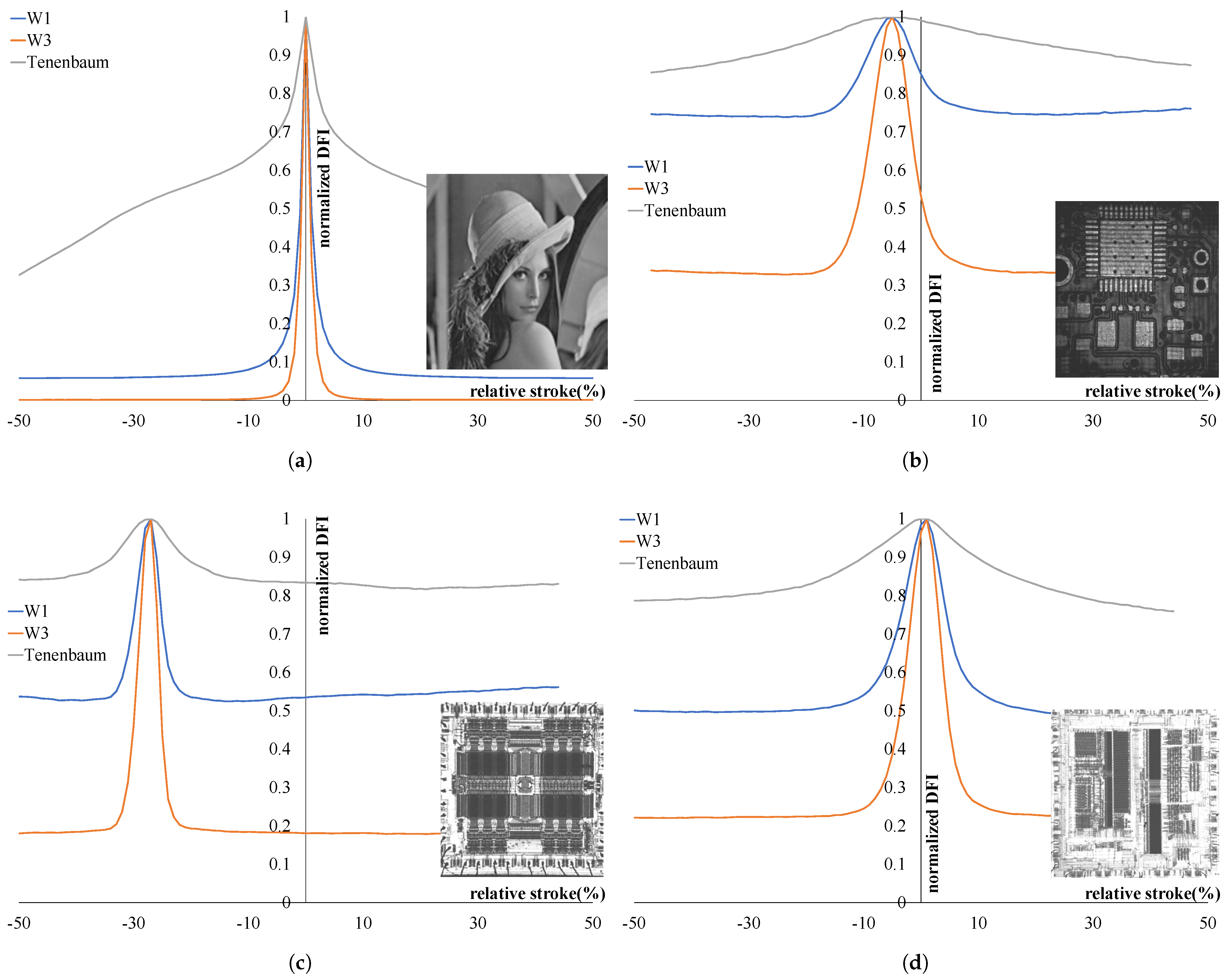
The focus accuracy of the WDFI was evaluated for real autofocus using smoothing images of the gray standard Lena. Figure 3a shows the variations in the WDFIs according to the smoothing levels. The smoothing level is on the horizontal axis, and the distance from the original point symbolizes a focal point. The normalized values of the W1 and W3 DFIs are plotted on the vertical axis. The curves of the WDFIs were generally continuous, except at the original point. The WDFIs sharply increased around the focal point and formed sharp maxima, similar to the spike at the original point. This implies that WDFIs have high sensitivity at the focal point. The W1 DFI formed an offset from the horizontal axis as the defocus level increased; however, the W3 DFI converged to zero. In contrast to the Tenenbaum gradient, focus was determined at the same positions as those identified by WBA. The W1 and W3 produced sharper responses near the focal position than the Tenenbaum gradient, indicating that the sensitivity of WBA was higher than that of gradient-based AF. Figure 3b–d show the responses of the WDFI and the Tenenbaum gradient using real-focusing image sequences. The vertical axes represent the normalized index, while the horizontal axes indicate the relative stroke of focus movement. In most cases, focus was determined at the same positions, with a maximum positional error of 1% across the full stroke range. Among the tested DFIs, W3 exhibited the highest sensitivity near focal positions, whereas the Tenenbaum gradient was less responsive. These results demonstrate that the developed kernel is applicable to autofocus in practical machine vision systems.

3.2. Wavelet Sum

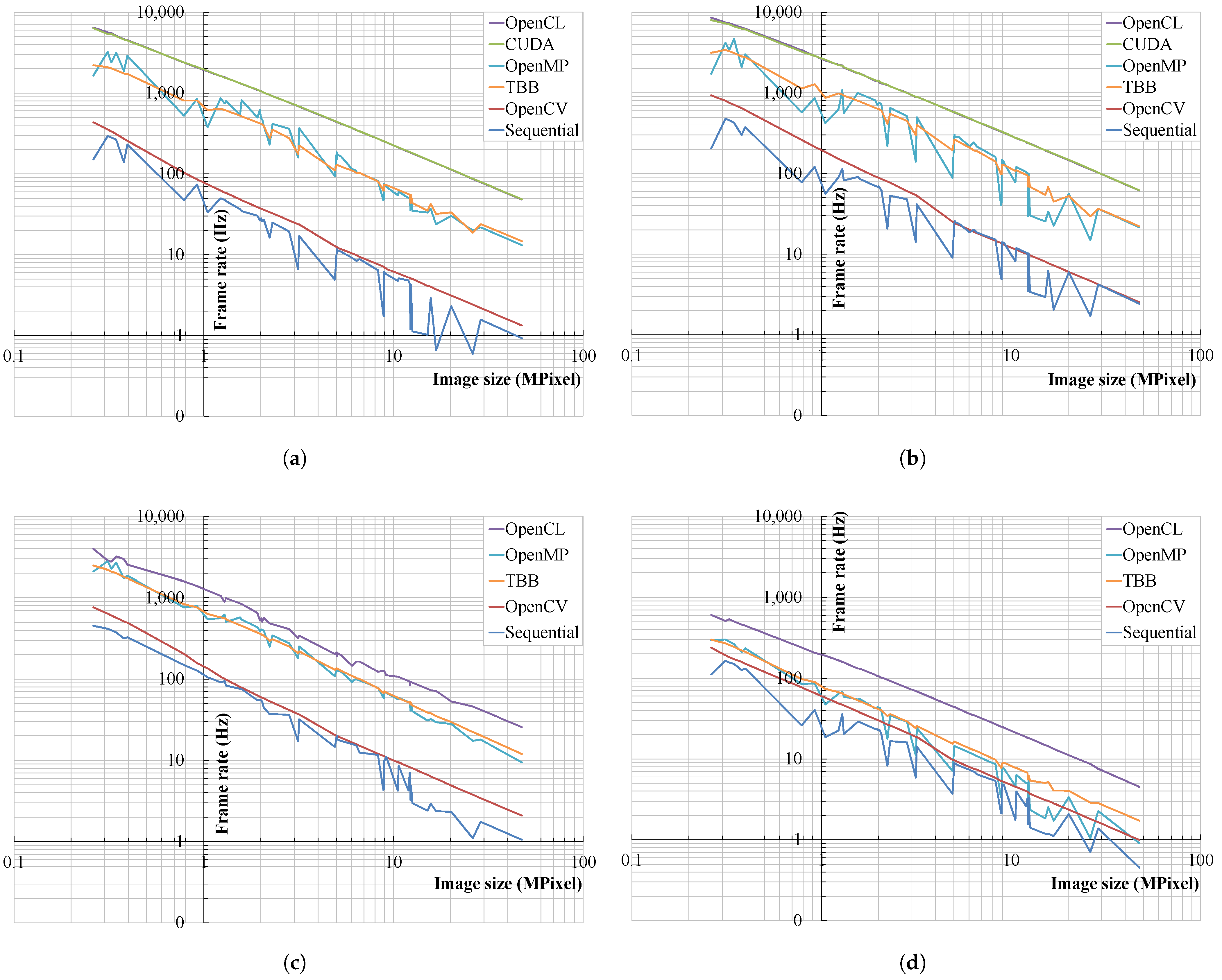
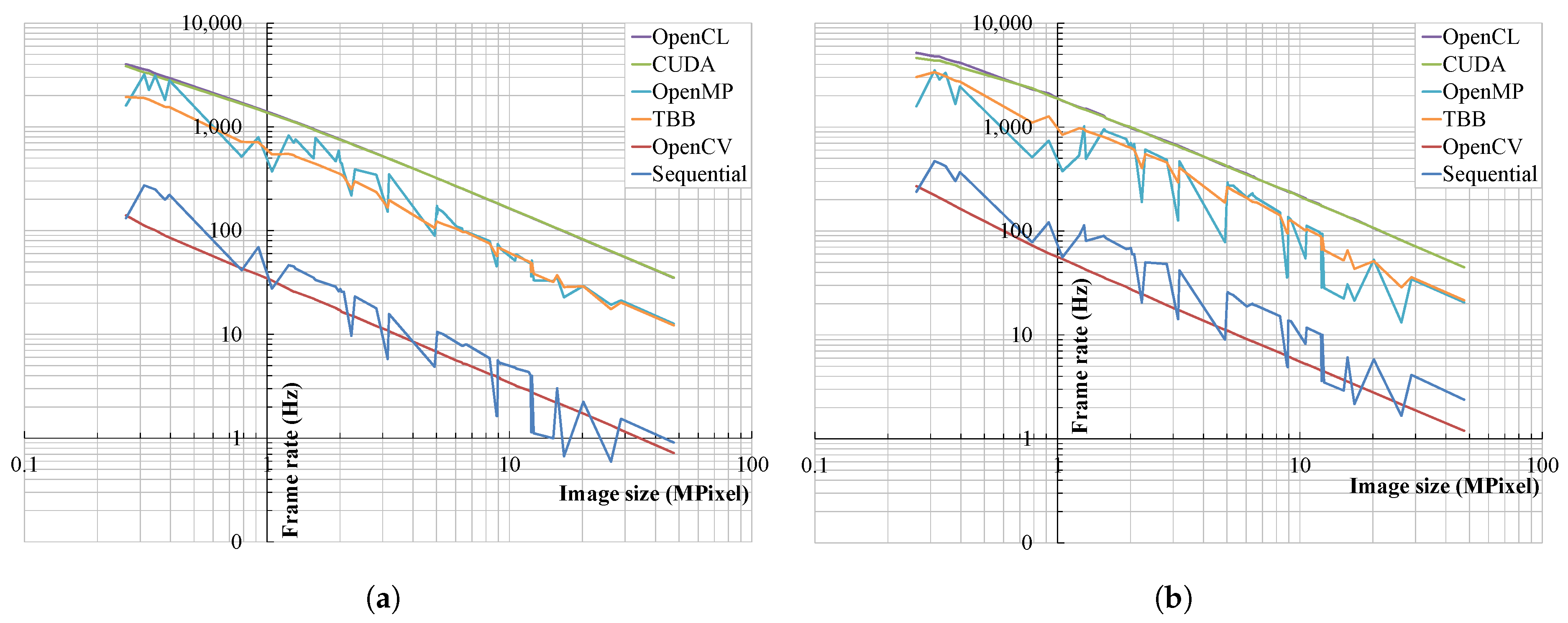
The frame rate is the number of processed images per second; thus, the processing speed was shown using the frame rate in this study. The frame rate unit is Hz or fps. The frame rate variation of the W1 DFI for 8-bit images is shown in Figure 4. The horizontal and vertical axes indicate the frame rate (Hz) and image size, respectively. In general, the frame rates showed a linear decrease in the log scale according to the image size. The curves in Figure 4 can be classified into three groups: GPU, MCP, and non-parallel. The GPU group was the result of CUDA and OpenCL. The frame rates of the GPU group were superior to those of other groups. The frame rates of CUDA and OpenCL using peripheral GPUs almost coincide, as shown in Figure 4a,b, respectively. The MCP group using OpenMP and TBB showed lower frame rates than those of the GPU group but provided higher frame rates than those of the non-parallel group. The variations in frame rates using CPU-resident GPUs can be observed in Figure 4c,d. CPU-resident GPUs are incompatible with CUDA; thus, only the OpenCL performance is presented in this study. The frame rates of the GPU group were also higher than those of other groups, although the frame rates were lower than those of the peripheral GPUs. Thus, the CPU-resident GPU was also effective in computing the W1 DFI. The frame rate curves of sequential and OpenMP fluctuated significantly and formed sharp edges, whereas those of the GPU, TBB, and OpenCV were smooth. Sharp edges on the curves were observed when image sizes were divisible by powers of two between 2048 and 8192. These anomalies may be attributed to memory page alignment, cache memory behavior, and thread scheduling.
The frame rates for the 45 MPixel image using peripheral GPUs were 48.4 and 61.9 Hz, respectively; thus, the peripheral GPUs are suitable for real-time focusing. The frame rates for the 10 MPixel image using the CPU-resident GPUs were 107.1 and 21.2 Hz; therefore, the CPU-resident GPUs can be used for practical autofocus. The UHD Graphics 770 GPU (Intel Corp., Santa Clara, CA, USA) provides only FP32 for floating-point operations; thus, the frame rates were higher, but the floating-point error was larger than that of FP64. The IPC has limited resources for industrial applications; however, the GPU achieved 21.2 Hz for the 10 MPixel image, whereas the MCP and OpenCV provided 4.6 and 4.5 Hz, respectively.
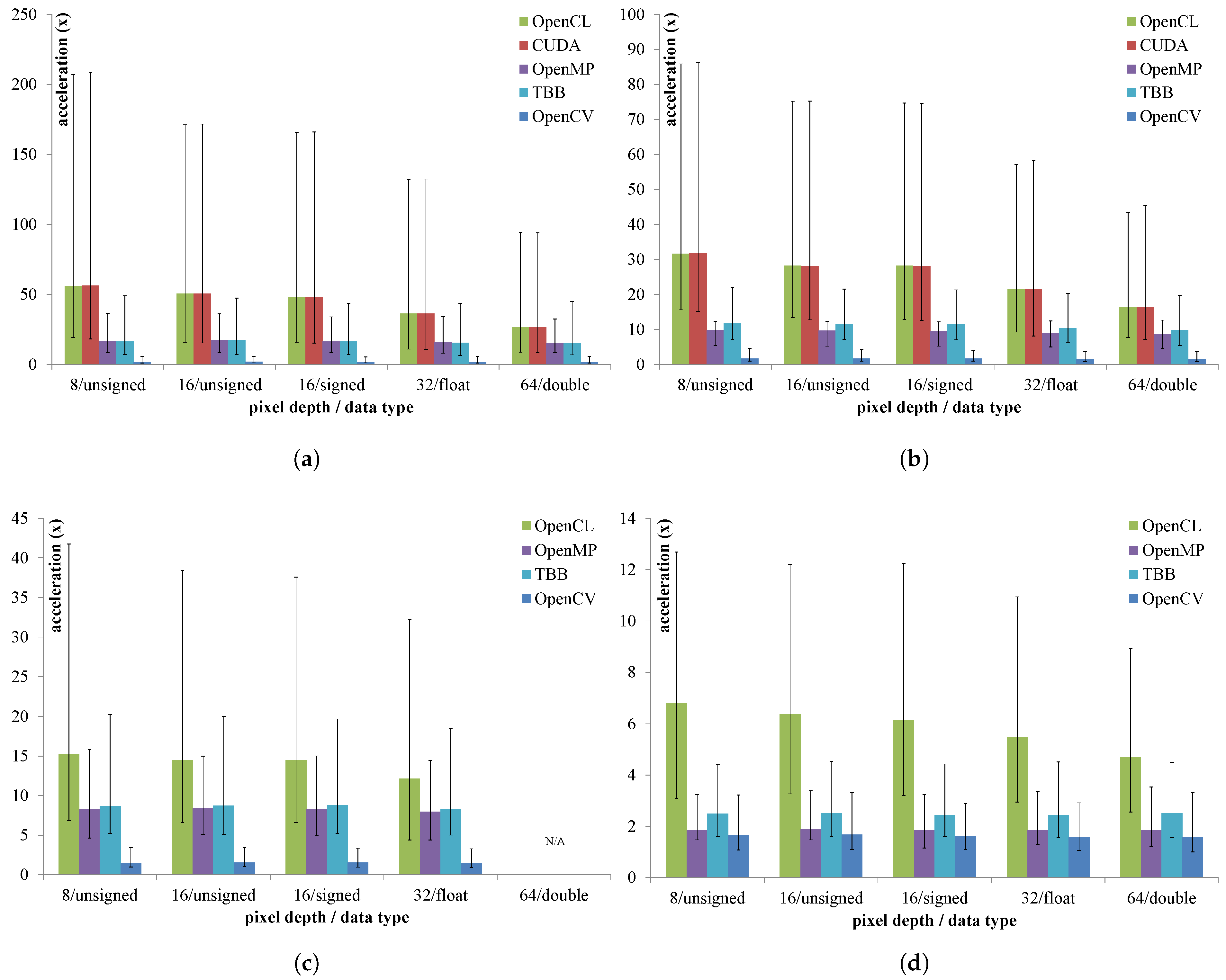
Figure 5 illustrates the computational acceleration achieved through parallel processing in comparison to sequential processing. Acceleration is defined as the ratio of frame rates between the open-source implementation and the sequential baseline. The thin lines represent the band between maximum and minimum acceleration values, while the bars indicate the average acceleration. As shown in Figure 5a,b, the frame rates of the peripheral GPUs using CUDA and OpenCL are almost the same. This indicates that the OpenCL API is sufficiently optimized; thus, it is reliable for CPU-resident and non-CUDA GPUs. This also implies that OpenCL performance can represent GPU performance for comparison with other GPUs. In the case of the MCP, the TBB frame rates were slightly higher than those of OpenMP. The acceleration using the peripheral GPUs was higher than that of the MCP, and the best case was 208.6× for an 8-bit pixel-bit depth when using the RTX2070 (NVIDIA, Santa Clara, CA, USA). The highest average acceleration was 56.3× using the same device. CPU-resident GPUs are usually budget GPUs; however, they are also effective for the computational acceleration of the W1 DFI, as shown in Figure 5c,d. The absolute values of the acceleration were lower than those of the peripheral GPUs; however, the budget GPUs were still superior to the MCP. The FP32 GPU in the mini PC achieved 15.2× and 41.7× for the cases of maximum average and best accelerations, respectively. The GPU in the IPC for machine vision achieved 6.7× and 12.6× acceleration for the same cases. Thus, the GPUs generally accelerate the W1 DFI more than the MCP and can decrease the computational cost. Thus, the GPU is the most effective device for accelerating the computation of the W1 DFI, followed by MCPs. OpenCV was slightly effective in accelerating the W1 DFI, but the performance improvement was minute compared with those of the parallel devices.

3.3. Wavelet Variance

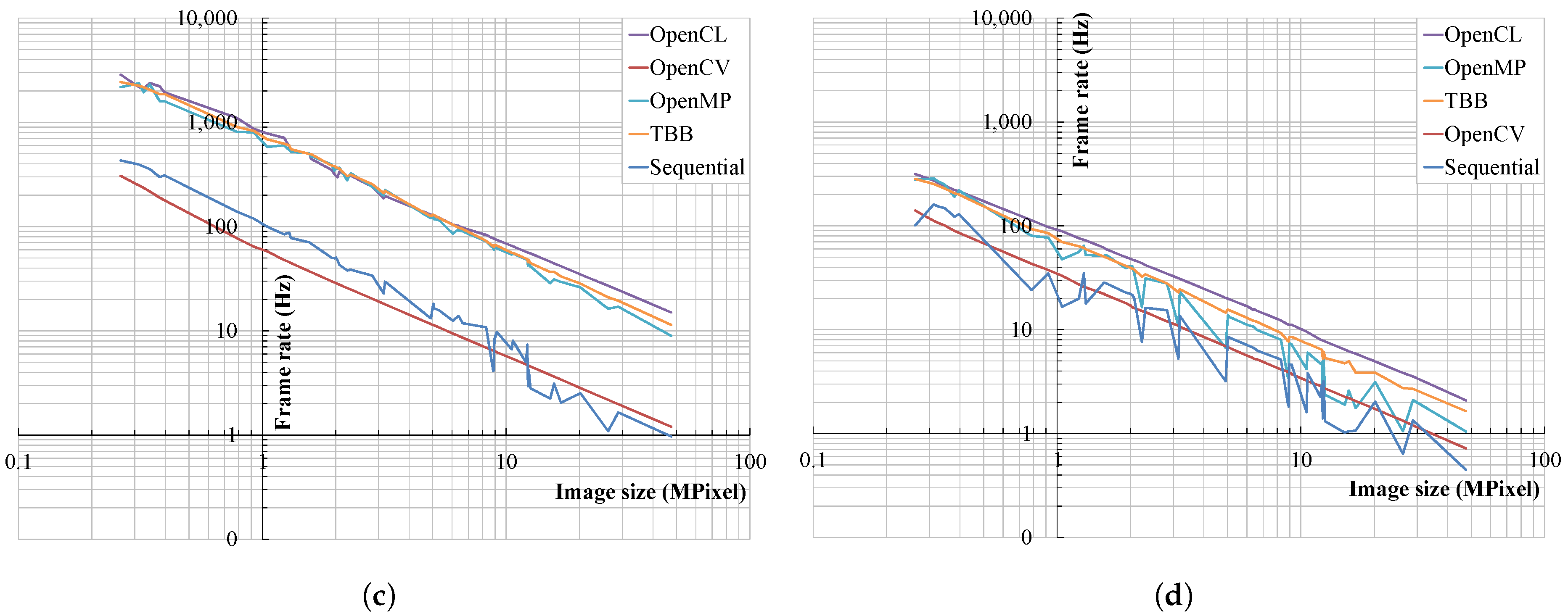
The frame rate variation of the W3 DFI for 16-bit images is shown in Figure 6. Several industrial cameras acquired 10 to 14 bit images and stored them in the 16-bit tiff format. The overall trends of the W3 DFI were almost the same as those of the W1 DFI described in the previous section. The results in Figure 6 show a linear decrease in the log scale and form smooth curves in CUDA, OpenCL, TBB, and OpenCV. The GPU, MCP, and non-parallel groups were also observed, and the GPU group presented the highest frame rates. The frame rates of the GPU group almost coincide, as shown in Figure 4a,b. The frame rates achieved by the MCP group were similar to those achieved by the GPU group. The variations in frame rates using CPU-resident GPUs is displayed in Figure 6c,d. The frame rates of the GPU group were generally the highest, but the gaps between the GPU and MCP groups were reduced compared with the W1 DFI. As shown in Figure 6c,d, the frame rates of the GPUs were slightly higher than those of the MCP; however, the difference was small. The frame rate curves of the GPU, TBB, and OpenCV were smooth like the cases in wavelet sum.
The frame rates for the 45 MPixel image using peripheral GPUs were 35.0 and 44.7 Hz. The frame rates for the 10 MPixel images using CPU-resident GPUs were 15.0 and 9.5 Hz. The GPU in the IPC can assist the W3 DFI computation and improve the computational efficiency by interlinking open sources.
Figure 7 compares the acceleration of parallel processing with that of conventional sequential processing. The frame rates of the peripheral GPUs using CUDA and OpenCL in Figure 7a,b exhibit the same trends as those in Figure 5a,b. The maximum accelerations of the GPUs are approximately equal. Acceleration using CPU-resident GPUs was also effective, as shown in Figure 5c,d. However, the frame rate differences between the GPU and MCP were reduced. In the case of MCPs, OpenMP was slightly better than TBB on desktop1, but TBB was better on the other hardware platforms.
The acceleration when using the peripheral GPUs was generally higher than that when using the MCP; however, the difference was reduced, particularly when using the CPU-resident GPUs. The best case was 170.9× for a 16-bit pixel-bit depth when using the RTX2070. The highest average acceleration was 48.1× using the same device. Figure 7c,d shows the acceleration when using CPU-resident GPUs. The GPUs were generally effective and superior to the MCP in this case, but the improvement was minimal. The accelerations of the GPU in the mini PC were 10.5× and 26.8× for the maximum average and best cases, respectively. The GPU in the IPC achieved accelerations of 3.3× and 6.6× for the same cases. Thus, GPUs are more effective for the W3 DFI compared with the MCP and can also reduce the computational cost. In the case of MCP processing, TBB was better than OpenMP but not desktop1.

4. Discussion

The frame rate curves of the WDFIs during autofocus, as shown in Figure 3, are generally continuous, monotonic, and smooth. The peak was placed exactly at the focal point, and the bandwidth of the peak was narrow. Thus, WDFIs are sensitive to focal points and provide accurate and reliable autofocus. These WDFI characteristics have also been observed in the comparative studies of various DFIs [58].
From the results in Figure 4 and Figure 6, GPUs had excellent effects on decreasing the computational cost of WDFIs. It is impressive that CPU-resident GPUs were also effective for computational acceleration, although they are budget-intensive and not used extensively in practice. Peripheral GPUs are used by advanced users; thus, they are effective for acceleration. The RTX2070 was released in 2018 and is outdated; however, the results show that it is still useful for the accelerating the WDFI. The frame rate variations of the GPUs in Figure 4 and Figure 6 are smooth and continuous; thus, the acceleration performance is stable and reliable. GPUs of the HD series are included in several Intel CPUs but are not used in practice. In addition, the commercial GPUs in this study usually aim at integer-based processing but are not optimized for 64-bit. In commercial GPUs, 64-bit double-precision computation is inefficient compared with 32-bit conventional computation [59]. However, the results demonstrated that GPUs were still superior to the CPU in 64-bit processing, although the frame rates of 64-bit double-precision computations dropped sharply compared with those of lower-bit computations.
When the pixel-bit depth increased, a decrease in acceleration was observed when using the GPUs. The difference in the frame rates between the MCPs and GPUs was reduced, as shown in Figure 5 and Figure 7. The average and maximum accelerations using the GPUs commonly decreased according to the pixel-bit depth; however, the acceleration using the MCP did not vary significantly. The pixel-bit depth is related to the amount of data transferred to the GPUs. GPUs have a typical data transfer problem, known as a bottleneck [60]. Thus, the amount of data transferred increases according to the pixel-bit depth, which increases the computational cost of using a GPU.
In most cases shown in Figure 5 and Figure 7, CUDA executed on peripheral GPUs demonstrates slightly better performance than OpenCL as CUDA is generally more optimized for NVIDIA hardware. However, in our experiments, the kernels were executed on Ubuntu Linux, where the performance advantage of CUDA may be diminished due to system-level factors such as driver behavior and runtime overhead.
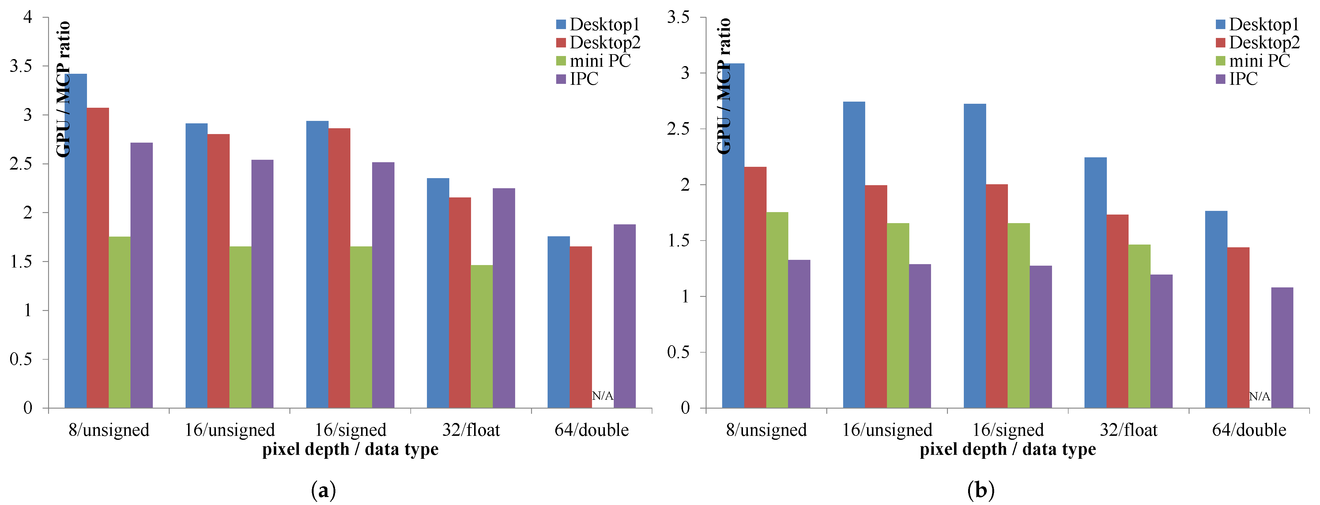
Considering the compatibility of open-source libraries, OpenCL, TBB, OpenMP, and OpenCV are commonly available on various computational platforms. CUDA is applicable only to NVIDIA GPUs; however, the frame rates obtained using OpenCL were almost the same as those obtained using CUDA. OpenCL was operated on a gfx1036 GPU (AMD, Santa Clara, CA, USA) included in the AMD CPU of desktop2 in additional tests. OpenCL was compatible with the NVIDIA, Intel, and AMD platforms; thus, OpenCL performance can be used to compare those of different GPU platforms. Furthermore, TBB and OpenMP are available on most commercial CPUs, and the curves of the frame rates using TBB are smooth and fluctuate less. Thus, OpenCL and TBB performance can be used as criteria to compare the performance of different computational platforms. Figure 8 shows the acceleration ratio of average acceleration between the GPU and MCP.
The acceleration ratios in the results were higher than 1.0, implying that the GPU was advantageous for the WBA. The peripheral GPUs had higher ratios because they were designed for advanced users and powerful arithmetic operations. CPU-resident GPUs are usually left unused; thus, they are economical to use because installation expenses are unnecessary. Therefore, the choice of GPUs to replace high-end GPUs is widened for wavelet-based computations. Processing and hardware costs can be reduced by CPU-resident GPUs. The IPC is designed for industrial applications, and its hardware specifications are limited; however, the CPU-resident GPU is effective in improving the computational performance. This implies that the IPC is mainly used for machine vision; therefore, its performance can be maximized using CPU-resident GPUs. Most studies on computational acceleration use high-end peripheral GPUs. However, the results imply that the unused GPU can be a great resource for the acceleration of wavelet-based methods.
The frame rates were compared with those reported in previous studies. Pertuz presented 18.1 and 9.8 Hz for W1 and W3 DFIs using quad core Pentium IV [55]. The image size was 640 × 480, and the HD Graphics 520 GPU (Intel Corp., Santa Clara, CA, USA) in the IPC results in 510.5 and 268.8 Hz using a similar size. Another study showed 9.8 Hz for the W1 DFI using a 2088 × 1550 image [61], and the GPU of the IPC achieved 68.4 Hz using a similar size. The performance ratio can be estimated using the results of the gradient-based method, to which the wavelet-based method belongs. Valdiviezo-N and Castillo-Secilla experimented with the Tenengrad DFI using 1200 × 1600 and 2560 × 1940 images on a 24 core Xeon workstation and Jetson TX1 embedded board, and the ratios were approximately 1.6 and 14.6, respectively, [40,62]. The WDFI is much more complex than the Tenengrad DFI, and our results were 2.5 and 4.0 using the IPC and desktop2, respectively. The GPUs in previous studies also tended to be superior to the MCP for the WDFIs. Parallel implementations of the wavelet sum and variations are applicable for accelerating image processing in addition to the autofocus. The wavelet sum in image processing has been discussed in studies on denoising [63], reconstruction [64], and demosaiking [65]. Wavelet sum has also been explored for multivariable signal processing [66] and data mining [67]. Thus, the parallel implementation of WDFIs lowers the computational cost of autofocus and will be helpful in various research areas. In the future, our parallel implementation will be expanded to include MacOS and other mobile platforms.

5. Conclusions

A parallel method in WBA was implemented to accelerate the mathematical processing and increase the computational efficiency. A parallel implementation of wavelet sum and variance using DB6 was presented for conventional MCP and GPU processing. The WBA includes DB6 convolution, biorthogonal decomposition, and summing of high-frequency subbands. MCP processing was used to perform wavelet computation on the subimage, and the DFI was evaluated by integrating the results of the subimages. GPU processing proceeded with wavelet computation on a pixel array similar to the scanning image, and the DFI was obtained via parallel reduction. The WDFI kernels were implemented using open sources such as standard C++, OpenCV, OpenMP, OpenCL, and CUDA. The results demonstrated that both the GPUs and MCP were effective in accelerating the WDFI computation; however, the performance of the GPU was superior to that of the MCP. It is impressive that the CPU-resident GPUs also effectively accelerated the WDFI. Considering that the CPU-resident and budget GPUs are neglected in numerous PCs, CPU-resident GPUs are excellent resources for wavelet processing. In the IPC for industrial machine vision, which had limited resources, the CPU-resident GPU was effective in decreasing the computational cost of the WDFI. Therefore, we verified that a GPU is an essential device for the WDFI and will be useful to wavelet-based computation.
The key contribution of this study is the finding that CPU-resident GPUs can effectively accelerate the WDFI. These GPUs are often underutilized in standard desktop environments, but they can serve as valuable computational resources for WBA. This suggests that the proposed implementation is applicable not only in engineering but also in office desktops used for documentation, finance, and other service-oriented domains. In future work, we plan to present parallel implementations of additional WBA methods and expand into cross-platform development. This includes exploring WBA applications for mobile devices running Android and iOS. As mobile devices continue to evolve with higher resolutions and an increasing number of image sensors, the need for acceleration of AF will become even more crucial.

Author Contributions

Conceptualization, H.K.; methodology, H.K.; software, H.K.; validation, D.-Y.L. and D.C.; formal analysis, D.C.; investigation, D.-Y.L.; resources, D.-Y.L.; data curation, H.K.; writing—original draft preparation, H.K.; writing—review and editing, D.-W.L.; visualization, D.C.; supervision, D.-W.L.; project administration, D.-W.L.; funding acquisition, D.-W.L. All authors have read and agreed to the published version of the manuscript.

Funding

This research was funded by the MSCT and KOCCA grant number RS-2024-00439361.

Institutional Review Board Statement

Not applicable.

Informed Consent Statement

Not applicable.

Data Availability Statement

Data are contained within the article.

Conflicts of Interest

The authors declare no conflicts of interest.

Abbreviations

The following abbreviations are used in this manuscript:
ALUArithmetic Unit
APIApplication Program Interface
DB6Daubechies 6
DFIDigital Focus Index
DWTDiscrete Wavelet Transformation
FBAFilter Bank Algorithm
GPUGeneral Processing Unit
IPCIndustrial Process Controller
MCPMulticore Processor
PCPersonal Computer
UISUnsupervised Image Segmentation
WBAWavelet-Based Autofocus
WDFIWavelet-Based Digital Focus Index

References

  1. Jang, J.; Lee, S.; Hwang, S.; Lee, J. A Study on Denoising Autoencoder Noise Selection for Improving the Fault Diagnosis Rate of Vibration Time Series Data. Appl. Sci. 2025, 15, 6523. [Google Scholar] [CrossRef]
  2. Arunachalaperumal, C.; Dhilipkumar, S. An Efficient Image Quality Enhancement using Wavelet Transform. Mat. Today Proc. 2020, 24, 2004–2010. [Google Scholar] [CrossRef]
  3. Kumar, G.S.; Rani, M.L.P. Image Compression Using Discrete Wavelet Transform and Convolution Neural Networks. J. Electr. Eng. Technol. 2024, 19, 3713–3721. [Google Scholar] [CrossRef]
  4. Jiang, X.; Ma, K.; Wu, J.; Li, Z. Bridge Damage Identification Based on Variational Modal Decomposition and Continuous Wavelet Transform Method. Appl. Sci. 2025, 15, 6682. [Google Scholar] [CrossRef]
  5. Ramamonjisoa, M.; Firman, M.; Watson, J.; Lepetit, V.; Turmukhambetov, D. Single Image Depth Prediction with Wavelet Decomposition. In Proceedings of the IEEE/CVF Conference on Computer Vision and Pattern Recognition, Nashville, TN, USA, 20–25 June 2021; pp. 11084–11093. [Google Scholar]
  6. Widjaja, J.; Jutamulia, S. Use of wavelet analysis for improving autofocusing capability. Opt. Commun. 1998, 151, 12–14. [Google Scholar] [CrossRef]
  7. Um, G.; Hur, N.; Kim, H.; Cho, J.; Lee, J. Control Parameter Extraction using Wavelet Transform for Auto-Focus Control of Stereo Camera. J. Brod. Eng. 2000, 5, 239–246. [Google Scholar]
  8. Acharya, T.; Metz, W. Auto-Focusing Algorithm Using Discrete Wavelet Transform. U.S. Patent 6151415A, 21 November 2000. [Google Scholar]
  9. Yang, G.; Nelson, B.J. Micromanipulation Contact Transition Control by Selective Focusing and Microforce Control. In Proceedings of the IEEE International Conference on Robotics and Automation, Taipei, Taiwan, 14–19 September 2003; pp. 3200–3206. [Google Scholar]
  10. Nguyen, K.; Do, K.; Vu, T.; Than, K. Unsupervised image segmentation with robust virtual class contrast. Pattern Recognit. Lett. 2023, 173, 10–16. [Google Scholar] [CrossRef]
  11. Niu, D.; Wang, X.; Han, X.; Lian, L.; Herzig, R.; Darrell, T. Unsupervised Universal Image Segmentation. In Proceedings of the IEEE/CVF Conference on Computer Vision and Pattern Recognitio, Seattle, WA, USA, 16–22 June 2024; pp. 22744–22754. [Google Scholar]
  12. Forster, B.; Van De Ville, D.; Berent, J.; Sage, D.; Unser, M. Extended depth-of-focus for multi-channel microscopy images: A complex wavelet approach. In Proceedings of the IEEE International Symposium on Biomedical Imaging: Nano to Macro, Arlington, VA, USA, 18 April 2004; pp. 660–663. [Google Scholar]
  13. Tsai, D.; Wang, H. Segmenting focused objects in complex visual images. Pattern Recognit. Lett. 1998, 19, 929–940. [Google Scholar] [CrossRef]
  14. Wang, J.Z.; Li, J.; Gray, R.M.; Wiederhold, G. Unsupervised multiresolution segmentation for images with low depth of field. IEEE Trans. Pattern Anal. Mach. Intell. 2001, 23, 85–90. [Google Scholar] [CrossRef]
  15. Zhou, Y.; Huang, J.; Wang, C.; Song, L.; Yang, G. XNet: Wavelet-Based Low and High Frequency Fusion Networks for Fully- and Semi-Supervised Semantic Segmentation of Biomedical Images. In Proceedings of the IEEE/CVF International Conference on Computer Vision, Paris, France, 1–6 October 2023; pp. 21028–21039. [Google Scholar]
  16. Qian, X.; Lu, W.; Zhang, Y. Adaptive wavelet-VNet for single-sample test time adaptation in medical image segmentation. Med. Phys. 2024, 51, 8865–8881. [Google Scholar] [CrossRef]
  17. Wang, Z. Unsupervised Wavelet-Feature Correlation Ratio Markov Clustering Algorithm for Remotely Sensed Images. Appl. Sci. 2024, 14, 767. [Google Scholar] [CrossRef]
  18. Mertens, F.; Lobanov, A. Wavelet-based decomposition and analysis of structural patterns in astronomical images. Astron. Astrophys. 2015, 574, A67. [Google Scholar] [CrossRef]
  19. Kautsky, J.; Flusser, J.; Zitová, B.; Šimberová, S. A new wavelet-based measure of image focus. Pattern Recognit. Lett. 2002, 23, 1785–1794. [Google Scholar] [CrossRef]
  20. Yang, G.; Nelson, B.J. Wavelet-based autofocusing and unsupervised segmentation of microscopic images. In Proceedings of the IEEE/RSJ International Conference on Intelligent Robots and Systems, Las Vegas, NV, USA, 27–31 October 2003; pp. 2143–2148. [Google Scholar]
  21. Zong, G.; Sun, M.; Bi, S.; Dong, D. Research on Wavelet Based Autofocus Evaluation in Micro-vision. Chin. J. Aeronaut. 2006, 19, 239–246. [Google Scholar] [CrossRef]
  22. Xie, H.; Rong, W.; Sun, L. Construction and evaluation of a wavelet-based focus measure for microscopy imaging. Microsc. Res. Tech. 2007, 70, 987–995. [Google Scholar] [CrossRef]
  23. Makkapati, V.V. Improved wavelet-based microscope autofocusing for blood smears by using segmentation. In Proceedings of the IEEE International Conference on Automation Science and Engineering, Bangalore, India, 22–25 August 2009; pp. 208–211. [Google Scholar]
  24. Akiyama, A.; Kobayashi, N.; Mutoh, E.; Kumagai, H.; Yamada, H.; Ishii, H. Infrared image guidance for ground vehicle based on fast wavelet image focusing and tracking. SPIE Opt. Eng. Appl. 2009, 7429, 742906. [Google Scholar]
  25. Wang, Z.; He, X.; Wu, X. An autofocusing technology for core image system based on lifting wavelet transform. J. Sichuan Univ. Nat. Sci. Ed. 2008, 45, 838–841. [Google Scholar]
  26. Fan, Z.; Chen, S.; Hu, H.; Chang, H.; Fu, Q. Autofocus algorithm based on Wavelet Packet Transform for infrared microscopy. In Proceedings of the IEEE International Congress on Image and Signal Processing, Yantai, China, 16–18 October 2010; pp. 2510–2514. [Google Scholar]
  27. Mendapara, P.; Baradarani, A.; Wu, Q.M.J. An efficient depth map estimation technique using complex wavelets. In Proceedings of the IEEE International Conference on Multimedia and Expo, Singapore, 19–23 July 2010; pp. 1409–1414. [Google Scholar]
  28. Śliwiński, P. Autofocusing with the help of orthogonal series transforms. Int. J. Electron. Telecommun. 2010, 56, 33–42. [Google Scholar] [CrossRef]
  29. Abele, R.; Fronte, D.; Liardet, P.Y.; Boi, J.M.; Damoiseaux, J.L.; Merad, D. Autofocus in infrared microscopy. In Proceedings of the IEEE International Conference on Emerging Technologies and Factory Automation, Turin, Italy, 4–7 September 2018; pp. 631–637. [Google Scholar]
  30. Yin, A.; Chen, B.; Zhang, Y. Focusing evaluation method based on wavelet transform and adaptive genetic algorithm. Opt. Eng. 2012, 51, 023201. [Google Scholar] [CrossRef]
  31. Wu, X.; Zhou, H.; Yu, H.; Hu, R.; Zhang, G.; Hu, J.; He, T. A Method for Medical Microscopic Images’ Sharpness Evaluation Based on NSST and Variance by Combining Time and Frequency Domains. Sensors 2022, 22, 7607. [Google Scholar] [CrossRef]
  32. Surh, J.; Jeon, H.; Park, Y.; Im, S.; Ha, H.; Kweon, I.S. Noise Robust Depth from Focus Using a Ring Difference Filter. In Proceedings of the IEEE Conference on Computer Vision and Pattern Recognition, Honolulu, HI, USA, 21–26 July 2017; pp. 2444–2453. [Google Scholar]
  33. Herrmann, C.; Bowen, R.S.; Wadhwa, N.; Garg, R.; He, Q.; Barron, J.T.; Zabih, R. Learning to Autofocus. In Proceedings of the IEEE/CVF Conference on Computer Vision and Pattern Recognition, Seattle, WA, USA, 13–19 June 2020; pp. 2227–2236. [Google Scholar]
  34. Piao, W.; Han, Y.; Hu, L.; Wang, C. Quantitative Evaluation of Focus Measure Operators in Optical Microscopy. Sensors 2025, 25, 3144. [Google Scholar] [CrossRef] [PubMed]
  35. Wang, Y.; Wu, C.; Gao, Y.; Liu, H. Deep Learning-Based Dynamic Region of Interest Autofocus Method for Grayscale Image. Sensors 2024, 24, 4336. [Google Scholar] [CrossRef]
  36. Chen, T.; Li, H. Segmenting focused objects based on the Amplitude Decomposition Model. Pattern Recognit. Lett. 2012, 33, 1536–1542. [Google Scholar] [CrossRef]
  37. Liu, S.; Liu, M.; Yang, Z. An image auto-focusing algorithm for industrial image measurement. EURASIP J. Adv. Signal Process. 2016, 2016, 70. [Google Scholar] [CrossRef]
  38. Ahn, S.; Lee, S.; Kang, M.G. Lightweight Super-Resolution for Real-World Burst Images Captured by Handheld Camera Sensors Based on Partial Differential Equations. IEEE Sens. J. 2025, 25, 25241–25251. [Google Scholar] [CrossRef]
  39. Kim, H.; Kim, Y.H.; Moon, S.; Kim, H.; Yoo, B.; Park, J.; Kim, S.; Koo, J.M.; Seo, S.; Shin, H.J.; et al. A 0.64 µm 4-Photodiode 1.28 µm 50Mpixel CMOS Image Sensor with 0.98e- Temporal Noise and 20Ke- Full-Well Capacity Employing Quarter-Ring Source-Follower. In Proceedings of the IEEE International Solid-State Circuits Conference, San Francisco, CA, USA, 19–23 February 2023; pp. 1–3. [Google Scholar]
  40. Castillo-Secilla, J.M.; Saval-Calvo, M.; Medina-Valdès, L.; Cuenca-Asensi, S.; Martínez-Álvarez, A.; Sánchez, C.; Cristóbal, G. Autofocus method for automated microscopy using embedded GPUs. Biomed. Opt. Express 2017, 8, 1731–1740. [Google Scholar] [CrossRef]
  41. Kim, H.; Lee, D.; Choi, D.; Kang, J.; Lee, D. Parallel Implementations of Digital Focus Indices Based on Minimax Search Using Multi-Core Processors. KSII Trans. Internet Inf. Syst. 2023, 17, 542–558. [Google Scholar] [CrossRef]
  42. Tenllado, C.; Setoain, J.; Prieto, M.; Piñuel, L.; Tirado, F. Parallel Implementation of the 2D Discrete Wavelet Transform on Graphics Processing Units: Filter Bank versus Lifting. IEEE Trans. Parallel Distrib. Syst. 2008, 19, 299–310. [Google Scholar] [CrossRef]
  43. Rodriguez-Martinez, E.; Benavides-Alvarez, C.; Aviles-Cruz, C.; Lopez-Saca, F.; Ferreyra-Ramirez, A. Improved Parallel Implementation of 1D Discrete Wavelet Transform Using CPU-GPU. Electronics 2023, 12, 3400. [Google Scholar] [CrossRef]
  44. Puchala, D.; Stokfiszewski, K. Highly Effective GPU Realization of Discrete Wavelet Transform for Big-Data Problems. In Proceedings of the International Conference on Computational Science, Krakow, Poland, 16–18 June 2021; pp. 213–227. [Google Scholar]
  45. Kolomenskiy, D.; Onishi, R.; Uehara, H. WaveRange: Wavelet-based data compression for three-dimensional numerical simulations on regular grids. J. Vis. 2022, 25, 543–573. [Google Scholar] [CrossRef]
  46. de Cea-Dominguez, C.; Moure, J.C.; Bartrina-Rapesta, J.; Aulí-Llinàs, F. GPU Architecture for Wavelet-Based Video Coding Acceleration. Adv. Parallel Comput. 2020, 36, 83–92. [Google Scholar]
  47. Wu, H.; Wang, X.; Zhao, X.; Qiao, X.; Wang, X.J.; Qiu, X.J.; Fu, Z.; Xiong, C. Parallel Acceleration Algorithm for Wavelet Denoising of UAVAGS Data Based on CUDA. Nucl. Eng. Technol. 2025, 57, 103811. [Google Scholar] [CrossRef]
  48. Sun, Y.; Duthaler, S.; Nelson, B.J. Autofocusing in computer microscopy: Selecting the optimal focus algorithm. Microsc. Res. Tech. 2004, 65, 139–149. [Google Scholar] [CrossRef] [PubMed]
  49. Shahbahrami, A. Algorithms and architectures for 2D discrete wavelet transform. J. Supercomput. 2012, 62, 1045–1064. [Google Scholar] [CrossRef]
  50. Zhang, D.; Liu, Y.; Zhao, Y.; Liang, J.; Sun, B.; Chu, S. Algorithm Research on Detail and Contrast Enhancement of High Dynamic Infrared Images. Appl. Sci. 2023, 13, 12649. [Google Scholar] [CrossRef]
  51. Lindfield, G.; Penny, J. Chapter 8—Analyzing Data Using Discrete Transforms. In Numerical Methods Using MATLAB, 4th ed.; Academic Press: London, UK, 2019; pp. 383–431. [Google Scholar]
  52. Chaver, D.; Tenllado, C.; Piñuel, L.; Prieto, M.; Tirado, F. Wavelet Transform for Large Scale Image Processing on Modern Microprocessors. Lect. Notes Comput. Sci. 2003, 2565, 549–562. [Google Scholar]
  53. Kim, H.; Song, J.; Seo, J.; Ko, C.; Seo, G.; Han, S.K. Digitalized Thermal Inspection Method of the Low-Frequency Stimulation Pads for Preventing Low-Temperature Burn in Sensitive Skin. Bioengineering 2025, 12, 560. [Google Scholar] [CrossRef] [PubMed]
  54. Jradi, W.A.R.; do Nascimento, H.A.D.; Martins, W.S. A GPU-Based Parallel Reduction Implementation. Commun. Comput. Inf. Sci. 2020, 1171, 168–182. [Google Scholar]
  55. Pertuz, S.; Puig, D.; Garcia, M.A. Analysis of focus measure operators for shape-from-focus. Pattern Recognit. 2013, 46, 1415–1432. [Google Scholar] [CrossRef]
  56. Ingwersen, C.K.; Danielak, A.H.; Eiríksson, E.R.; Nielsen, A.A.; Pedersen, D.B. Computer vision for focus calibration of photo-polymerization systems. In Proceedings of the ASPE and euspen Summer Topical Meeting, Berkeley, CA, USA, 22–25 July 2018; pp. 89–91. [Google Scholar]
  57. Hutchinson, J. Culture, Communication, and an Information Age Madonna. IEEE Prof. Commun. Soc. Newsl. 2001, 45, 1–6. [Google Scholar]
  58. Zhang, H.; Yao, J. Automatic Focusing Method of Microscopes Based on Image Processing. Math. Probl. Eng. 2021, 2021, 8243072. [Google Scholar] [CrossRef]
  59. Mao, Z.; Li, X.; Hu, S.; Gopalakrishnan, G.; Li, A. A GPU accelerated mixed-precision Smoothed Particle Hydrodynamics framework with cell-based relative coordinates. Eng. Anal. Bound. Elem. 2024, 161, 113–125. [Google Scholar] [CrossRef]
  60. Luis, C.; Garcia-Feal, O.; Nord, G.; Piton, G.; Legoût, C. Implementation of a GPU-enhanced multiclass soil erosion model based on the 2D shallow water equations in the software Iber. Environ. Model. Softw. 2024, 179, 106098. [Google Scholar] [CrossRef]
  61. Cabazos-Marín, A.R.; Álvarez-Borrego, J. Automatic focus and fusion image algorithm using nonlinear correlation: Image quality evaluation. Optik 2018, 164, 224–242. [Google Scholar] [CrossRef]
  62. Valdiviezo-N, J.C.; Hernandez-Lopez, F.J.; Toxqui-Quitl, C. Parallel implementations to accelerate the autofocus process in microscopy applications. J. Med. Imaging 2020, 7, 014001. [Google Scholar]
  63. Lun, D.P.K.; Hsung, T. Image denoising using wavelet transform modulus sum. In Proceedings of the IEEE International Conference on Signal Processing, Beijing, China, 12–16 October 1998; pp. 1112–1116. [Google Scholar]
  64. Hur, Y.; Zheng, F. Coset Sum: An Alternative to the Tensor Product in Wavelet Construction. IEEE Trans. Inf. Theory 2013, 59, 3554–3571. [Google Scholar] [CrossRef]
  65. Jeong, B.; Eom, I. Demosaicking Using Weighted Sum in Wavelet domain. In Proceedings of the IEEK Conference, Yongpyong, Republic of Korea, 18–20 June 2008; pp. 821–822. [Google Scholar]
  66. Ahalpara, D.P.; Verma, A.; Parikh, J.C.; Panigrahi, P.K. Characterizing and modelling cyclic behaviour in non-stationary time series through multi-resolution analysis. Pramana J. Phys. 2008, 71, 459–485. [Google Scholar] [CrossRef]
  67. Lemire, D. Wavelet-based relative prefix sum methods for range sum queries in data cubes. In Proceedings of the Conference of the Centre for Advanced Studies on Collaborative Research, Toronto, ON, Canada, 30 September–3 October 2002. [Google Scholar]
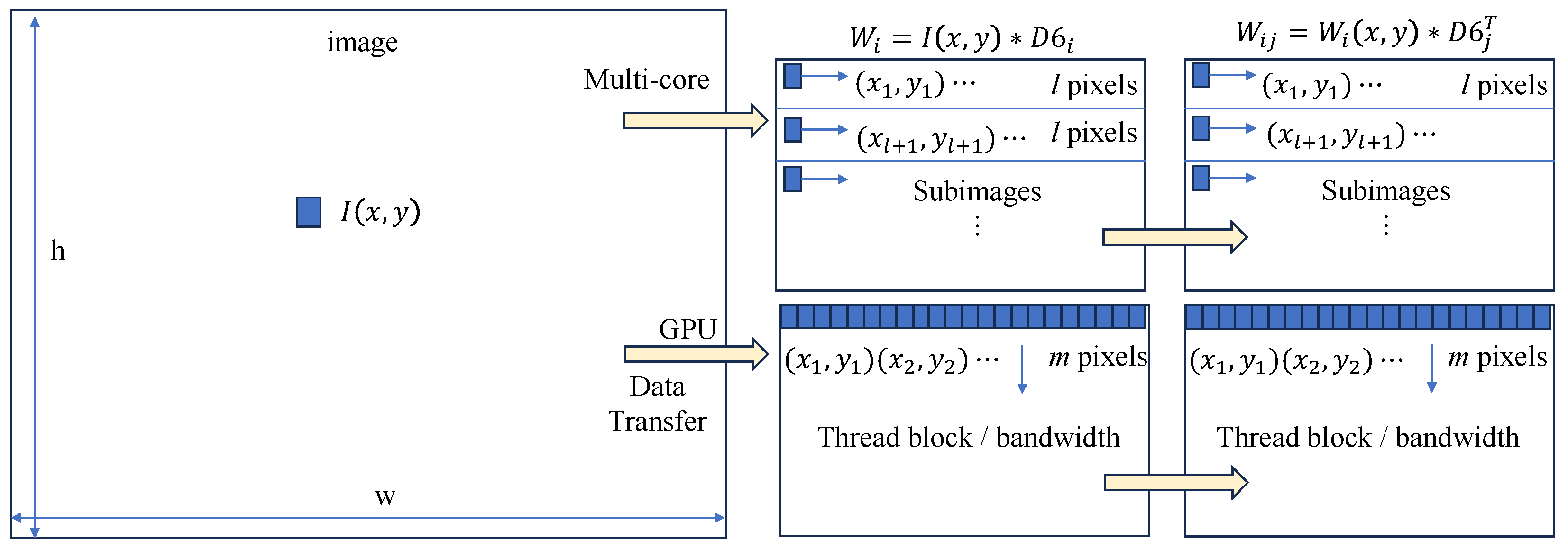
Figure 1. Parallelization strategies of 2D DWT for MCP and GPU.
Applsci 15 10455 g001
Figure 2. Parallel architecture for L1 norm of wavelet coefficients in subbands using MCP and GPU.
Applsci 15 10455 g002
Figure 3. Variation of normalized WDFIs with smoothing level for (a) Lenna image, (b) PCB, (c) EP910JC35, and (d) Z86E3012KSE.
Applsci 15 10455 g003
Figure 4. Frame rate variation of W1 DFI for 8-bit full-size images using (a) desktop1, (b) desktop2, (c) mini PC, and (d) IPC.
Applsci 15 10455 g004
Figure 5. Minimum, maximum, and average acceleration of W1 DFI for 8-bit full-size images using (a) desktop1, (b) desktop2, (c) mini PC, and (d) IPC.
Applsci 15 10455 g005
Figure 6. Frame rate variation of W3 DFI for 16-bit full-size images using (a) desktop1, (b) desktop2, (c) mini PC, and (d) IPC.
Applsci 15 10455 g006aApplsci 15 10455 g006b
Figure 7. Minimum, maximum, and average acceleration of W3 DFI for 16-bit full-size images using (a) desktop1, (b) desktop2, (c) mini PC, and (d) IPC.
Applsci 15 10455 g007
Figure 8. Acceleration ratio of (a) W1 and (b) W3 DFIs between GPU and MCP according to hardware.
Applsci 15 10455 g008
Table 1. API functions implemented for WDFIs supporting open-source platforms.
WDFIOpenCVAPI
W1cv::Mat Src, L, H, LH, HL, HH;
Src = cv::imread(FileName);
cv::filter2D(Src, L, CV_64F, DB6L);
cv::filter2D(Src, H, CV_64F, DB6H);
cv::filter2D(L, LH, CV_64F, DB6HT);
cv::filter2D(H, HL, CV_64F, DB6LT);
cv::filter2D(H, HH, CV_64F, DB6HT);
double lh = cv::norm(LH,cv::NORM_L1);
double hl = cv::norm(HL,cv::NORM_L1);
double hh = cv::norm(HH,cv::NORM_L1);
W1 = lh + hl + hh;
cv::Mat Src =
    cv::imread(FileName);
W1 = IndexWavelet1(Src);
W1 = ompWavelet1(Src);
W1 = tbbWavelet1(Src);
W1 = cuWavelet1(Src);
W1 = clWavelet1(Src);
W3cv::Mat Src, L, H, LH, HL, HH;
Src = cv::imread(FileName);
cv::filter2D(Src, L, CV_64F, DB6L);
cv::filter2D(Src, H, CV_64F, DB6H);
cv::filter2D(L, LH, CV_64F, DB6HT);
cv::filter2D(H, HL, CV_64F, DB6LT);
cv::filter2D(H, HH, CV_64F, DB6HT);
cv::Mat aLH = cv::abs(LH);
cv::Scalar mLH,sLH;
cv::meanStdDev(aLH, mLH, sLH);

W3 = sLH × sLH + sHL × sHL + sHH × sHH;
cv::Mat Src =
     cv::imread(FileName);
W3 = IndexWavelet3(Src);
W3 = ompWavelet3(Src);
W3 = tbbWavelet3(Src);
W3 = cuWavelet3(Src);
W3 = clWavelet3(Src);
Table 2. Specification of hardware for testing parallel implementations.
GPU GradeAdvanced-UserBudget
Hardware Desktop1 Desktop2 Mini PC IPC
PC VendorCustomCoolzenASRockCrevis
CPURyzen 3950XRyzen 7900Xi9-12900Ki7-6600U
CPU cores1612162
CPU VendorAMD (Santa Clara, CA, USA)AMDIntel (Santa Clara, CA, USA)Intel
RAM64 GB64 GB64 GB4 GB
GPURTX2070RTX4090UHD 770HD 520
GPU VendorNVIDIA (Santa Clara, CA, USA)NVIDIAIntelIntel
InterfacePCIePCIeCPU-residentCPU-resident
OSUbuntu 20.04Ubuntu 24.04Ubuntu 24.04Ubuntu 22.04
MCP ToolsOpenMP 1, TBB (Santa Clara, CA, USA)OpenMP, TBBOpenMP, TBBOpenMP, TBB
GPU ToolsCUDA (Santa Clara, CA, USA), OpenCL 2CUDA, OpenCLOpenCLOpenCL
PrecisionFP64FP64FP32FP64
Applicationsoffice desktopsoftware developmentcommercial kioskindustrial machine vision
1 OpenMP ARB, Beaverton, OR, USA. 2 OpenCL implementations are provided by GPU vendors through their device drivers.
Disclaimer/Publisher’s Note: The statements, opinions and data contained in all publications are solely those of the individual author(s) and contributor(s) and not of MDPI and/or the editor(s). MDPI and/or the editor(s) disclaim responsibility for any injury to people or property resulting from any ideas, methods, instructions or products referred to in the content.