Article

Efficiency Comparison and Optimal Voyage Strategy of CPP Combination and Fixed Modes Based on Ship Operational Data

by
Ji-Woong Lee
,
Quang Dao Vuong
,
Eun-Seok Jeong
,
Jung-Ho Noh
and
Jae-Ung Lee
*
Division of Marine System Engineering, National Korea Maritime and Ocean University, Busan 49112, Republic of Korea
*
Author to whom correspondence should be addressed.
Appl. Sci. 2025, 15(19), 10435; https://doi.org/10.3390/app151910435
Submission received: 24 August 2025 / Revised: 22 September 2025 / Accepted: 22 September 2025 / Published: 26 September 2025
(This article belongs to the Section Marine Science and Engineering)

Abstract

This study examines the efficiency trade-offs of Controllable Pitch Propeller (CPP) systems by comparing Combination and Fixed operation modes using real ship operational data. The analysis focuses on mechanical efficiency (ηmech), propulsive efficiency expressed through the normalized Relative Propulsive Efficiency Index (RPEInorm), and fuel consumption. Combination mode consistently maintained higher ηmech across all load conditions, with pronounced advantages at low load and low speed (<50% load, <12 knots), where both propulsive efficiency and fuel economy improved. In contrast, Fixed mode outperformed Combination mode at high load and high speed, exceeding approximately 50% load and 12 knots, as propeller performance approached its optimal operating point despite some sacrifice in engine efficiency. To integrate these effects, a proxy overall efficiency index (ηoverall,proxy = ηmech × RPEInorm) was introduced, revealing a crossover point at 0.525 load where the efficiency dominance shifted between modes. These findings demonstrate that neither mode is universally superior, but rather their advantages depend on operating conditions. The results provide practical insights for adaptive operational strategies, enabling real-time switching between modes to optimize fuel consumption and overall propulsion performance while supporting compliance with environmental regulations.

1. Introduction

1.1. Background

The International Maritime Organization (IMO) strengthened its regulatory measures on greenhouse gas (GHG) reduction and energy efficiency in international shipping at the 83rd session of the Marine Environment Protection Committee (MEPC 83) held in April 2025. Key outcomes included the adoption of a GHG fuel intensity management framework, the introduction of a differentiated emission trading scheme, and the mandatory real-time reporting of fuel consumption and emissions [1]. From 2028 onwards, ships will be required to comply with direct measures such as monitoring actual emissions and energy intensity by fuel type and purchasing emission allowances in cases of non-compliance with GHG reduction targets. Furthermore, existing energy efficiency frameworks, including the Energy Efficiency Existing Ship Index (EEXI), the Carbon Intensity Indicator (CII), and the Ship Energy Efficiency Management Plan (SEEMP), are expected to be further reinforced.
In response to the tightening of international regulations, enhancing fuel efficiency and optimizing propulsive performance have become essential tasks for ships, both to reduce operating costs and to ensure compliance with environmental requirements. The Controllable Pitch Propeller (CPP), which has been widely applied in modern vessels, is an advanced propulsion system that allows continuous adjustment of blade angle to adapt to diverse operating conditions such as speed, load, and maneuvering demands. The core of the CPP lies in its blade angle adjustment mechanism, which regulates the distance traveled by the propeller through the water per revolution, thereby optimizing propulsion efficiency and maneuverability. Unlike a Fixed Pitch Propeller (FPP), a CPP enables continuous speed control without the limitation of minimum engine RPM, and in emergency stop situations, it can switch immediately from ahead to astern, reducing the stopping distance to nearly half compared with an FPP. Depending on the operational strategy, CPP systems are generally categorized into two modes: the Combination mode and the Fixed mode, each characterized by distinct control philosophies and optimization strategies [2,3,4].
The Combination Mode is a control strategy that simultaneously adjusts both engine speed (RPM) and propeller pitch to achieve holistic optimization of the engine–propeller system. In this mode, the control system continuously searches for the optimal operating point in real time according to load variations, thereby ensuring that the engine operates within its most efficient range. The Automatic Load Control (ALC) algorithm maintains the target load level based on engine power output and fuel consumption characteristics, while the programmed control secures rational engine operation according to a pre-defined optimum RPM–pitch map. This multivariable control strategy demonstrates superior performance particularly under conditions of low-speed cruising, where fuel efficiency must be maximized, or in operating environments with frequent load fluctuations [5,6].
In contrast, the Fixed Mode is characterized by a simplified control structure in which engine speed is kept constant while propeller pitch alone is adjusted to regulate thrust. Owing to its simplicity, this mode ensures stable and predictable propulsion performance, with the Automatic Speed Control (ASC) algorithm accurately maintaining the target ship speed. Moreover, when a torque-based control strategy is applied, propulsion losses can be minimized even under external disturbances such as waves. Thanks to this stability and predictability, the Fixed Mode is widely adopted as a practical operational solution in situations requiring consistent propulsive power, such as high-speed cruising or long-distance voyages [7].

1.2. Research Necessity and Hypothesis

Recent studies have primarily focused on individual technological aspects of CPPs, such as engine–propeller matching optimization, multi-objective optimization-based control strategies, and fuel consumption minimization algorithms [8,9,10]. However, comprehensive comparative investigations of efficiency characteristics across different operating modes based on full-scale ship data remain limited.
Accordingly, this study proposes the following hypothesis: the Combination Mode consistently demonstrates higher transmission and propulsive efficiency across a wide range of load conditions, whereas the Fixed Mode provides relative advantages in terms of speed and fuel efficiency at higher load levels. Therefore, by conducting a comparative analysis of mechanical efficiency, propulsive efficiency, and fuel consumption characteristics of CPP under the two operational modes using training ship operational data, this study aims to provide scientific evidence for effective operational optimization and practical decision-making criteria in the context of the latest IMO regulations.

2. Literature Study

2.1. Comparative Studies on CPP Operating Modes

Research on the performance characteristics of Controllable Pitch Propellers (CPPs) under different operating modes has been primarily conducted through experimental approaches and numerical analyses. Deniz et al. investigated the influence of propeller pitch on propulsion performance using the Self-Propulsion Estimation (SPE) method, and further analyzed propulsive efficiency characteristics with reference to the Wageningen B-series propeller database. Their findings revealed that a higher propeller pitch does not necessarily lead to improved propulsion efficiency, and that the maximum propeller efficiency varies depending on the ship’s advance speed [11].
Moon et al. conducted a comparative analysis of the performance and exhaust gas characteristics of CPP operating modes using a training ship equipped with a two-stroke diesel engine at Pukyung National University. Through full-scale sea trials under both the Combination Mode and the Constant Mode, it was observed that both engines exhibited superior performance in the Combination Mode, whereas the Constant Mode generally resulted in lower NOx emissions [12].
Borba explained that around 50% load, Fixed Pitch Propellers can only adjust RPM or ship speed to control load, while Controllable Pitch Propellers can also change blade pitch. This makes CPP more flexible in handling load changes at mid-range operation [13].
Experimental and modeling studies further show that regular and adverse seas (propeller emergence, head-sea added resistance) materially affect propulsive demand and controllability, underscoring the need to assess CPP strategies under waves and currents [14,15,16].

2.2. Studies on Propulsion System Matching Optimization

Optimization of ship–engine–propeller matching is a critical factor that directly influences the overall efficiency of the propulsion system. Wang et al. employed a hybrid PSO–GA algorithm to optimize the matching between ship engines and propellers, and developed a free-surface propeller efficiency optimization model with propeller diameter, angular velocity, pitch ratio, and disk ratio as variables [17].
Tran et al. proposed a novel approach to address the engine–propeller–hull matching problem under real operating conditions. Their quantitative analysis revealed that, after five years of operation, a total power loss of 21.5% occurred, which was attributed to changes in propeller characteristics (6.5%), engine performance degradation (6.3%), and engine–propeller mismatching (8.7%) [18].

2.3. Propeller Design and Performance Optimization

Wang et al. developed a marine propeller parameterization model based on Non-Uniform Rational B-Splines (NURBS) for propeller optimization. By utilizing eight parameters and five categories of spanwise parameter distributions, they constructed a model to define hydrofoil and blade geometry. This model was combined with a Gene Expression Programming (GEP)-based hydrodynamic performance evaluation model and the NSGA-II algorithm, resulting in propellers with higher efficiency than the reference propeller [17].
Gao et al. introduced a novel combinator surface concept for the efficiency optimization of ships equipped with mechanical propulsion systems. Their methodology proved effective in identifying optimal matching points between engines and propellers under diverse operating conditions [9].

2.4. Propulsive and Transmission Efficiency of Shafting Systems

Propulsion system performance is critically influenced by the shafting arrangement and its components. Halilbeşe experimentally demonstrated that the application of composite drive shafts reduces torsional vibrations and improves transmission efficiency by an average of 2.3% [19]. Olsen proposed the concept of Energy Coefficients to quantify losses occurring in each component of the propeller–shaft–gearbox system, thereby providing systematic guidelines for shafting design optimization [20]. Shi et al. further decomposed the energy conversion process into engine efficiency (ηe), shaft and gearbox transmission efficiency (ηs·ηgb), propeller efficiency (ηo·ηr), and hull efficiency (ηh). Their study reported a 1.5–3% reduction in overall propulsion efficiency during operation compared with design values, attributing the loss to transmission efficiency deterioration under off-design conditions [21]. This research offers practical insights into identifying the causes of efficiency degradation, guiding maintenance intervals, and supporting material selection strategies.

2.5. Studies on Operating Mode Selection Strategies and Optimization

Research on operating mode switching and integrated control strategies has gained increasing attention as a means to enhance the practical applicability of CPP systems. In studies on power management and optimization of marine hybrid propulsion systems, approaches have been proposed that consider not only mode switching but also the entire power flow simultaneously. Fan et al. optimized mode-switching policies for hybrid vessels equipped with multiple power sources (diesel, electric, and battery) under various operational scenarios and demonstrated through full-scale operation simulations that fuel consumption could be reduced by up to 7%. This study highlights the necessity of integrated control across multiple propulsion sources, including CPP mode switching [10].
Gao et al. introduced a novel combinator surface concept for ship propulsion efficiency optimization, in which multivariate parameters such as RPM, pitch, and ship speed are modeled on a single surface to enable real-time identification of the optimal operating point. When applied in conjunction with a CFD-based performance prediction model, this integrated control framework achieved, on average, 5.5% higher overall propulsion efficiency compared to conventional Fixed and Combination Modes [9].
These studies underscore that operating mode selection strategies are a core challenge in CPP systems and provide strong support for the development of real-time mode-switching algorithms utilizing the ηoverall,proxy indicator proposed in this study.
Recent research trends have expanded in scope to encompass complex dynamic simulations, full-scale measurement data, customized optimization of hull–engine–propeller systems, and even integrated optimization that simultaneously considers fuel consumption, environmental impacts, and economic performance. In particular, advanced studies have been reported from a systems-integration perspective, including dynamic optimization of the entire ship powertrain, customized propulsion control, and fuel–emission coupled control strategies.
While most previous studies have focused on either efficiency characteristics of specific operating modes or on individual control algorithms, the distinctiveness of this study lies in its integrated analysis of crossover phenomena in terms of mechanical efficiency, propulsive efficiency, and fuel consumption, based on actual training ship operational data. By utilizing measured data from real operating conditions rather than relying solely on simulations, this study empirically identifies the trade-off structure of efficiency between operating modes and thereby provides a practical foundation for establishing effective operational strategies.

2.6. Literature Synthesis and Study Positioning

Table 1 summarizes representative CPP studies by theme: operation optimization, engine–propeller–hull matching, adaptive pitch control, design for total energy use, combinator (RPM–pitch–speed) operating maps, pitch–speed effects, and resistance variability due to fouling and waves. While this literature advances control and design perspectives, few works provide full-scale, side-by-side assessments of Combination versus Fixed modes or normalize propulsive performance to enable cross-mode comparison under real operating conditions. Addressing this gap, the present study uses full-scale data from the training ship HANNARA, introduces a normalized RPEI and a proxy overall efficiency metric to integrate engine and propeller effects, and quantifies a mode crossover around 0.5–0.525 load to inform adaptive mode-switching for voyage efficiency.

3. Methodology

3.1. Methodology Structure

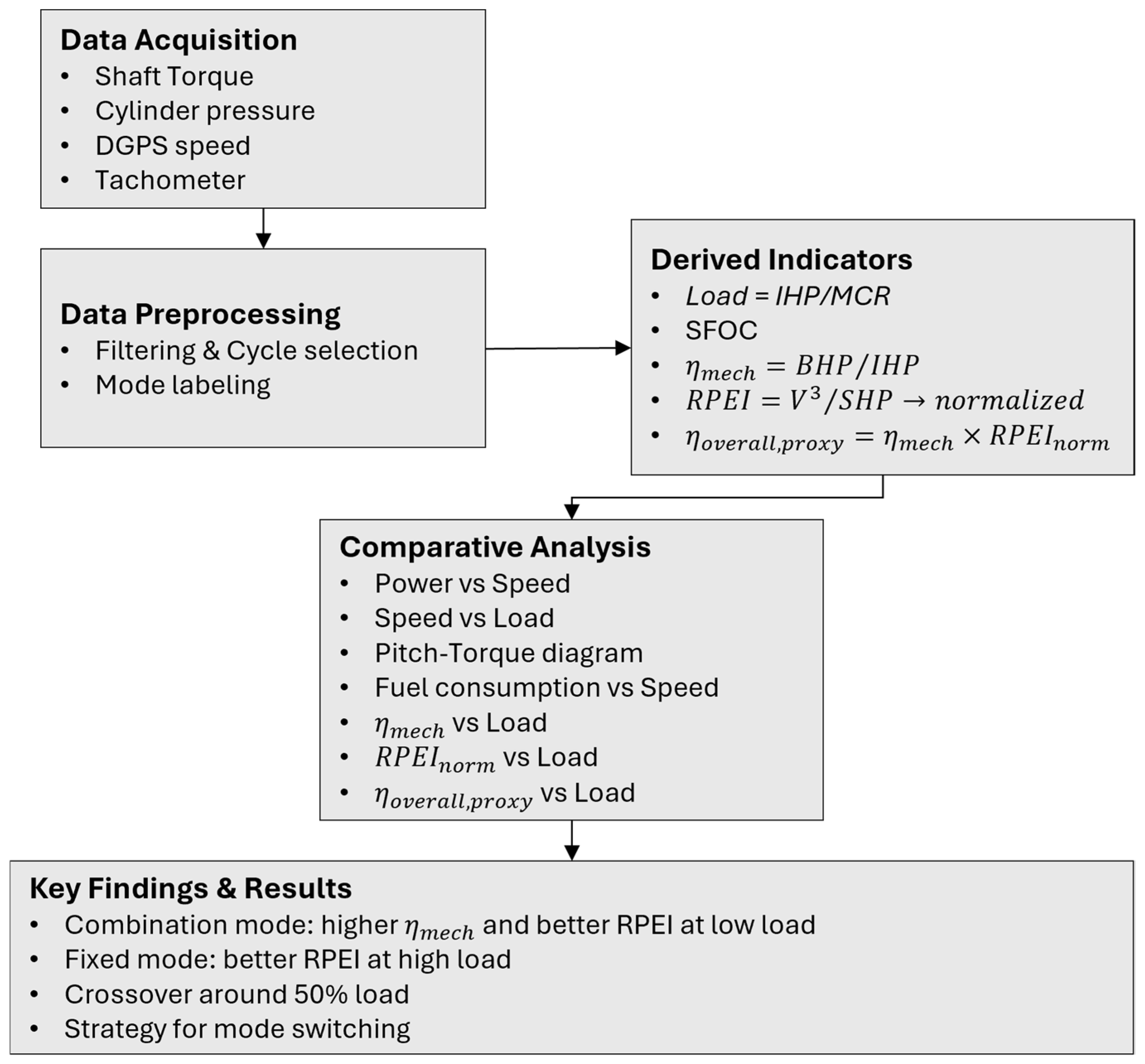
Figure 1 presents the overall research methodology adopted in this study. The process begins with full-scale data acquisition, followed by preprocessing for synchronization and mode labeling. Performance indicators such as load, SFOC, mechanical efficiency, RPEI, and the proxy overall efficiency are then derived. Comparative analyses are conducted across multiple variables, leading to key findings on the efficiency of trade-offs and crossover characteristics between Combination and Fixed modes.

3.2. Data and Methodology

This study investigates the propulsion system with a two-stroke diesel main engine installed on HANNARA training ship of the National Korea Maritime and Ocean University (KMOU). The principal specifications of the system are provided in Table 2.
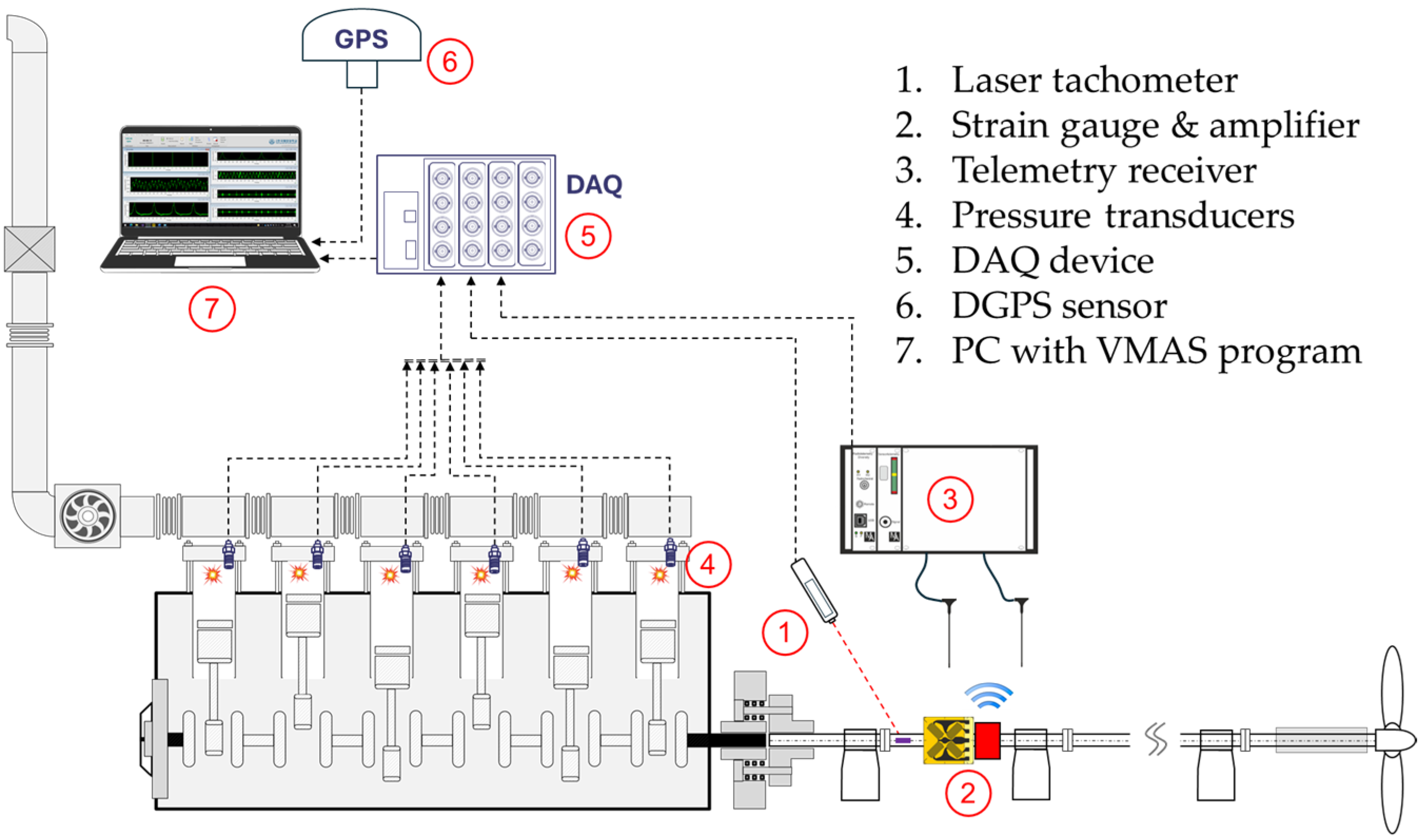
For the purpose of torque and effective power measurements on the intermediate shaft, a full-bridge strain gauge (model CEA-06-250US-350, Micro-Measurements, Wendell, NC, USA) was mounted on the shaft surface. Signal transmission from the strain gauge was achieved using a telemetry system supplied by MANNER Sensortelemetrie(Spaichingen, Germany), consisting of a rotating sensor signal amplifier (model SV_8a) coupled with a stationary receiver unit (model AW_42TE_Fu). The accuracy error is less than 0.02 % / . When the uncertainty from strain gauge installation is included, the combined uncertainty is less than 0.36% for a 10 °C temperature variation. To ensure measurement accuracy, the strain gauge system was calibrated using a shunt resistor just before measurements, with the engine in a stopped condition. Cylinder pressure signals were obtained from the main engine’s PMI Controller, which is equipped with an ABB PFPL203 combustion pressure transducer (Zürich, Switzerland) on each cylinder. The transducer calibrated measurement range extends from 0 to 250 bar, with combined measurement errors (including sensitivity drift, linearity deviation, and hysteresis) below ± 0.5 % .
Ship speed was measured using a DGPS sensor (model JLR-4341, JRC, Tokyo, Japan) installed on the navigation deck. Shaft rotational speed was determined with a laser tachometer (model A2103/LSR/001, Compact Instruments, Lancashire, UK) in conjunction with a reflective tape indicating the top dead center of cylinder No. 1. All measurement signals were synchronously acquired using a data acquisition system (NI-9174 Chassis with NI-9222 modules, National Instruments, Austin, TX, USA), digitized, and processed with VMAS (Vibration Monitoring and Analysis System) program developed by KMOU. Figure 2 describes the schematic diagram of measurement system. To ensure accurate and reliable detection of all relevant vibration phenomena, a sampling rate of 8192 samples per second was applied.
Using the measured in-cylinder pressure traces, the indicated power (IHP) was computed by evaluating the indicated mean effective pressure (IMEP) for each cylinder, cycle-averaging, and summing across cylinders. Because the propulsion train is a direct-coupled, brake power (BHP) was treated as effectively equal to the shaft horsepower (SHP) obtained from the strain-gauge-derived torque and tachometer RPM, with any minor transmission losses considered negligible within the sensors’ uncertainty.
Cycle-by-cycle measurements were acquired on the training ship under two CPP modes (Combination and Fixed). The dataset analyzed totals 11,378 engine cycles (≈4.10 × 10⁶ crank-angle samples at 360 points per cycle). Operating regimes were classified as LS-LL (<12 kn & <50% load), HS-HL (≥12 kn & ≥50%)

3.3. Performance Indicators

In this study, six performance indicators shown in Table 3 were established to quantitatively evaluate the operational characteristics of CPP modes. First, the load ratio was defined as the ratio of IHP to the Maximum Continuous Rating (MCR), representing the relative operating condition of the engine. Fuel efficiency was assessed using the Specific Fuel Consumption (SFC), which was estimated based on the reference value of 173.4 g/kWh (at 100% load, Tier II condition) provided in the engine manual, and its variation with load ratio. Accordingly, Fuel Consumption (FC) was calculated by multiplying IHP with the corresponding load-dependent SFC and converting the value into tons per hour.
For efficiency analysis, the mechanical efficiency (ηmech) was defined as the ratio of SHP to IHP, thereby reflecting the actual output efficiency accounting for internal engine losses. Since direct measurement of propulsive efficiency is challenging, a Relative Propulsive Efficiency Index (RPEI) was introduced. Based on the assumption that effective propulsive power is proportional to the cube of ship speed (V3) under identical hull form, draft, and sea conditions, RPEI was defined as V3/SHP, and normalized (RPEInorm) to a median value of one for mode-to-mode comparison. Finally, the proxy overall efficiency (ηoverall,proxy) was defined as the product of ηmech and RPEInorm, and employed as an integrated performance index that simultaneously reflects both engine and propeller efficiencies.

4. Results

4.1. Power vs. Ship Speed

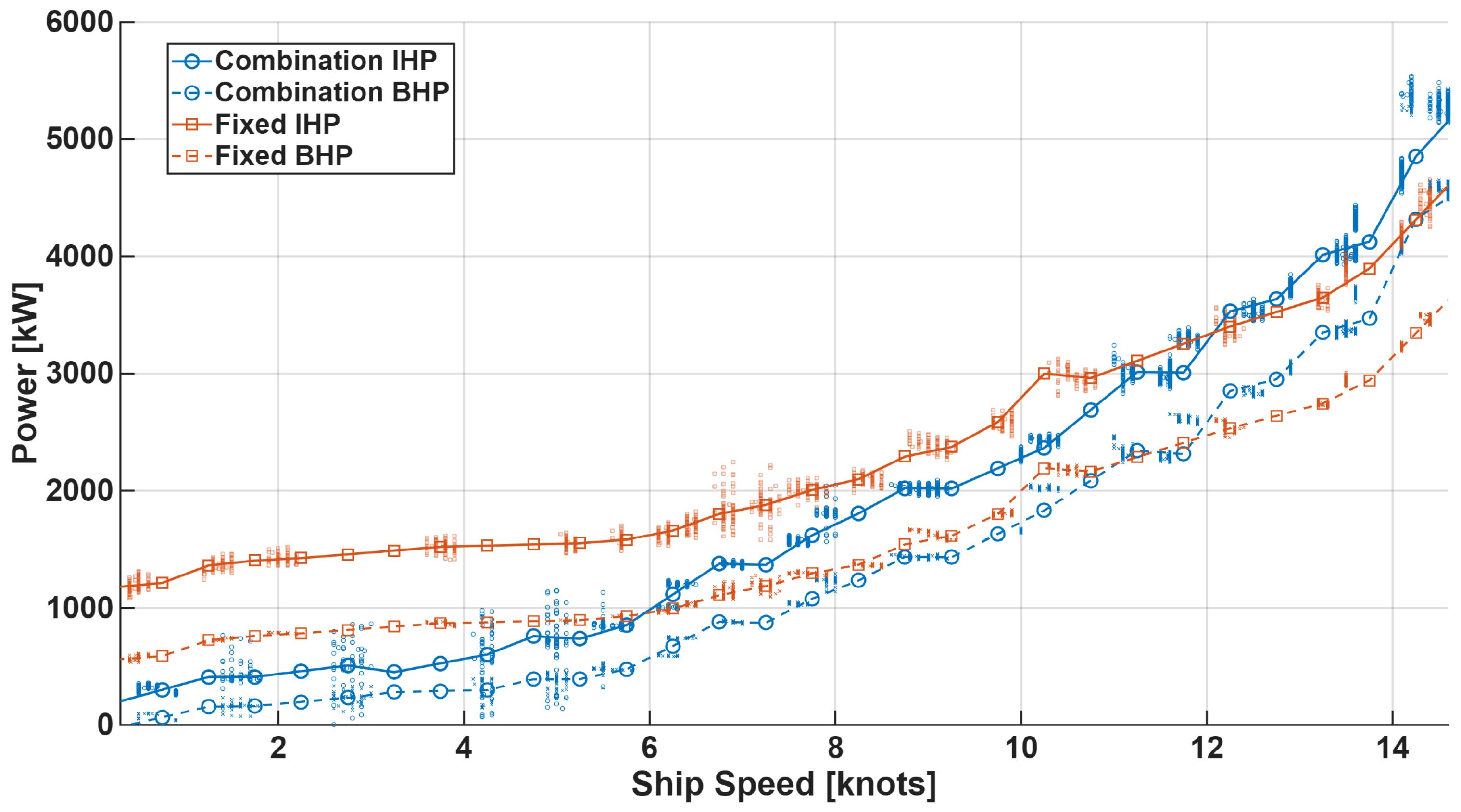
In this study, the IHP and BHP under each operating mode were compared as functions of ship speed. Figure 3 presents the averaged values, illustrating how power varies with ship speed.
Both IHP and BHP in the Combination and Fixed modes exhibited similar increasing trends across the entire speed range. However, in many cases at the same ship speed, the Fixed mode required higher power (IHP and BHP) than the Combination mode. Notably, in the low-speed region below 12 knots, the power demand of the Fixed mode consistently exceeded that of the Combination mode, whereas above 12 knots this relationship was reversed, with the Combination mode showing higher power demand.
These results suggest that in low-speed and low-load conditions, the Combination mode achieves relatively higher efficiency with reduced power loss, while the Fixed mode requires more power to maintain the same speed. In contrast, in the high-speed region (above 12 knots), the characteristics of the propulsion system and the behavior of the propeller efficiency curve lead to a crossover point where the relative advantage between the two operating modes is reversed.

4.2. Ship Speed vs. Load

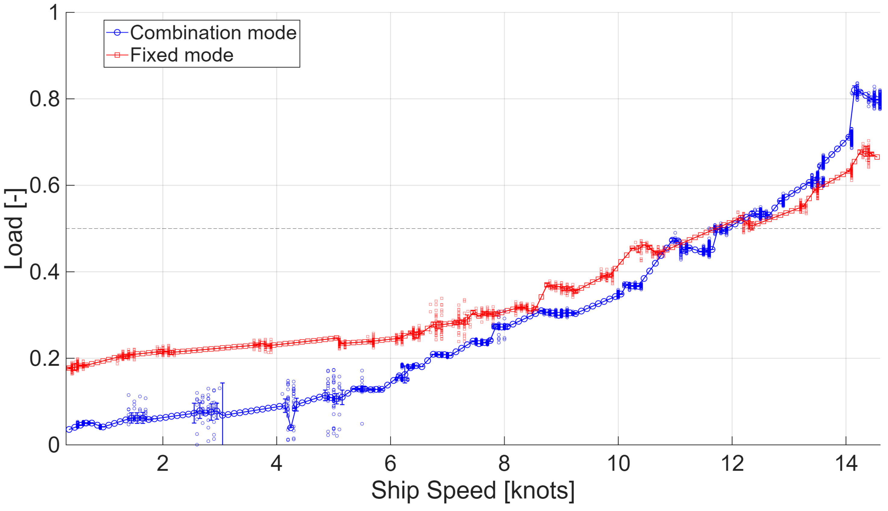
Figure 4 illustrates the relationship between ship speed and engine load under the two operating modes. The analysis revealed a distinct cross-over point between the two modes at approximately 12 knots and 50% load. Below 12 knots, the Combination mode required consistently lower load ratios than the Fixed mode to maintain the same ship speed, indicating an advantage in reducing fuel consumption. For example, at 6 knots, the Combination mode required a load ratio of about 0.15, whereas the Fixed mode demanded approximately 0.25.
In the range of 11–12 knots, the load demands of the two modes converged, forming a cross-over point. Beyond this point (approximately 50% load), as operating conditions shifted toward higher speed and higher load, the Fixed mode exhibited lower load ratios and consequently gained an advantage in terms of fuel efficiency.
This cross-over phenomenon indicates that the Combination mode is more favorable for minimizing fuel consumption in low-speed and low-load conditions, whereas the Fixed mode becomes more economical under high-speed and high-load conditions. Therefore, switching operating modes around 11–12 knots and 50% load could optimize fuel consumption across the entire operating envelope.

4.3. Pitch–Torque Relationship

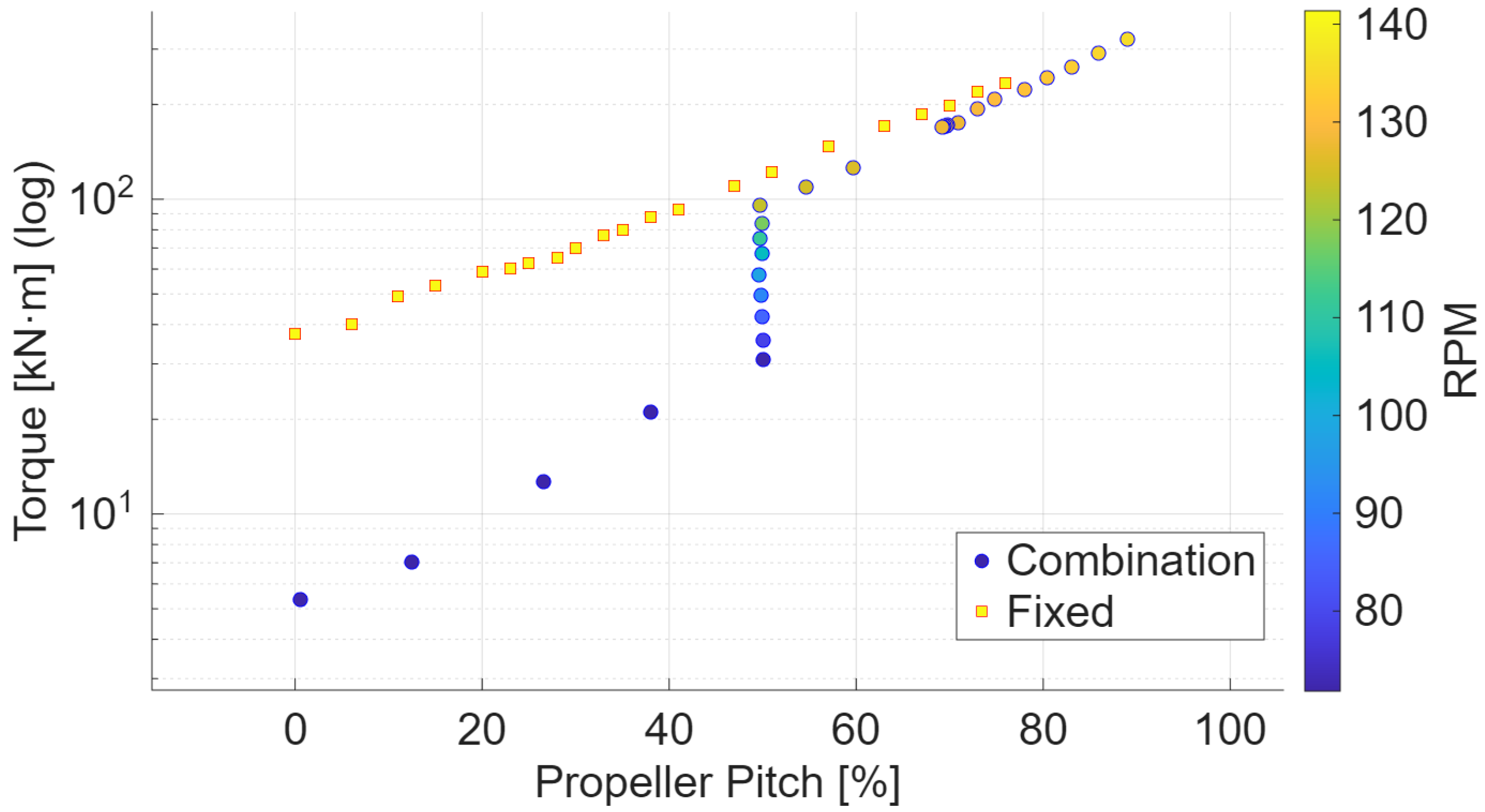
Figure 5 presents the relationship between propeller pitch and torque on a logarithmic scale, clearly highlighting the fundamental differences in control characteristics between the two operating modes. The color scale indicates engine RPM, and the analysis confirmed that torque follows a proportional relationship with pitch.
In the Fixed mode, torque was consistently proportional to pitch across the entire range, forming a stable and predictable linear trend. The data distribution was demonstrated the basic principle that torque can be linearly controlled through pitch variation while maintaining a constant engine speed of approximately 140 RPM.
In contrast, the Combination mode exhibited substantial data dispersion in the low-pitch region (20–50%), with a particularly vertical distribution of torque values observed near 50% pitch. This indicates an operating characteristic in which torque is regulated by increasing engine RPM while keeping pitch constant. Specifically, at 50% pitch, torque ranged widely from about 20 kN∙m to 100 kN∙m—more than a fivefold variation—demonstrating the mechanism of adjusting torque and propulsive force by varying engine RPM at a fixed pitch setting. At higher pitch levels (above 50%), the Combination mode converged toward the stable relationship observed in the Fixed mode.
These contrasting control methods distinguish the two modes: the Fixed mode employs a simple and predictable torque control strategy based on constant RPM and pitch variation, whereas the Combination mode allows more flexible control by combining adjustments in both RPM and pitch. The nearly linear trend observed in logarithmic scaling is consistent with the theoretical proportionality law of torque to pitch derived from propeller theory [18]. This near-proportional pitch–torque trend accords with established propeller open-water characteristics: increasing blade pitch at a given operating condition shifts the operating point toward higher torque/power demand, as documented in standard propeller maps and CPP practice [25]. The clearer linearity in Fixed mode reflects constant-RPM CPP operation, whereas the wider spread in Combination mode arises from simultaneous changes in RPM and pitch along the combinator schedule, a control behavior reported in CPP literature [26].
From a practical perspective, the Fixed mode offers predictability and stability, making precise torque management straightforward, while the Combination mode provides superior adaptability to varying operating conditions through its flexible control range. These characteristics help explain the efficiency differences analyzed earlier, illustrating that the multi-variable control of the Combination mode provides opportunities for optimization while simultaneously increasing control complexity.

4.4. Relationship Between Ship Speed and Fuel Consumption

To quantify the relationship between ship speed and FC across operating modes, fuel consumption was estimated using the IMO guideline–based SFOC–load correlation. The training ship is equipped with a HYUNDAI–MAN B&W 6S40ME-B9.5-LP SCR two-stroke diesel engine (rated power: 6618 kW at 146 rpm). A baseline SFOC of 173.4 g/kWh at 100% load was adopted and the load-dependent variation was modeled by Equation (1) in accordance with the IMO method [27,28]. Because the onboard fuel-flow meter signal could not be time-synchronized with the engine/shaft logs, the resulting FC is interpreted for relative comparisons across modes.
S F O C l o a d = S F O C b a s e l i n e × 0.455 × l o a d 2 0.71 × l o a d + 1.28
Here, SFOCload denotes the specific fuel oil consumption (g/kWh) at a given load, while load represents the relative engine load (0–1).
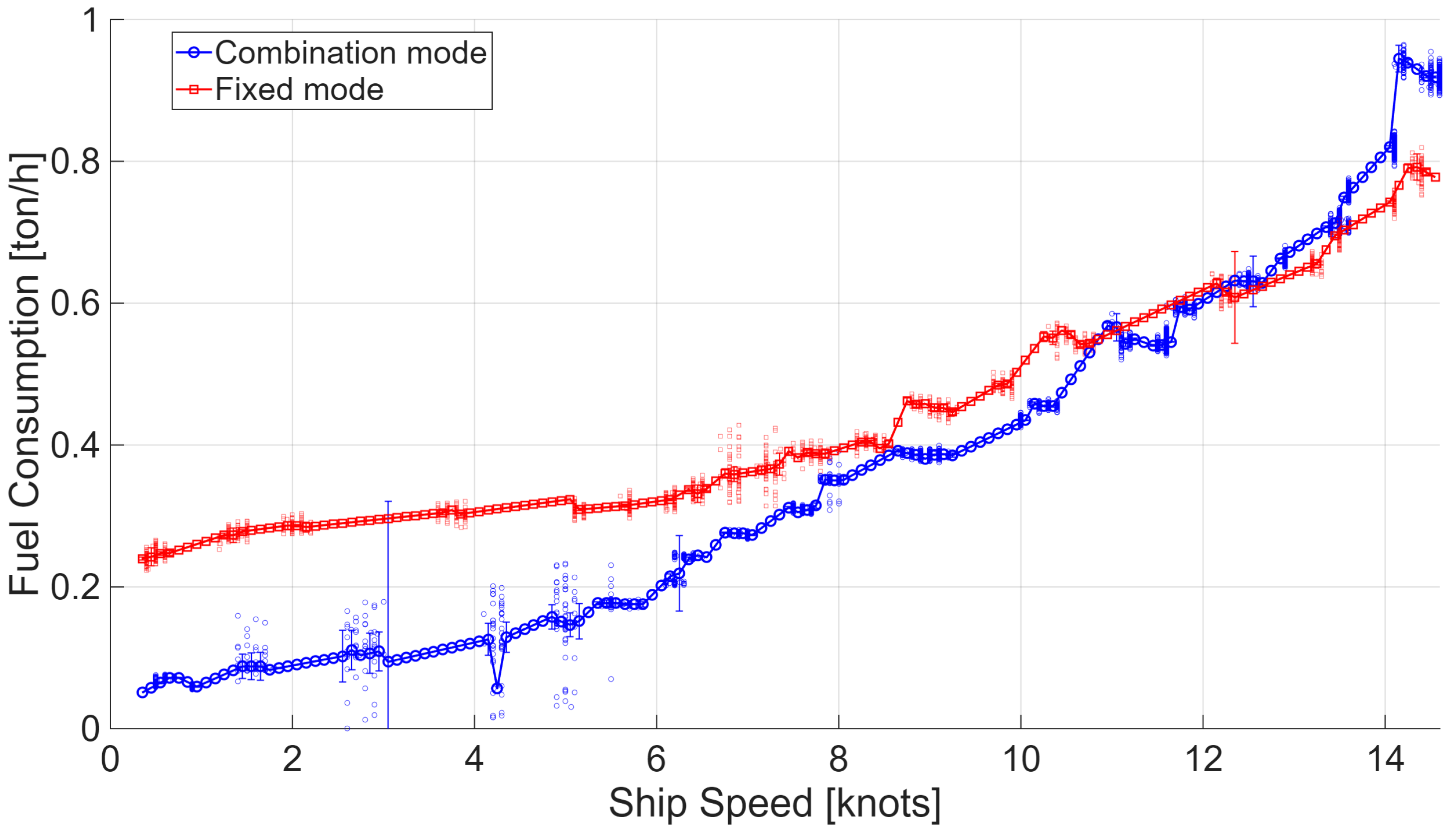
Figure 6 illustrates the relationship between ship speed and fuel consumption, where the previously identified cross-over phenomenon is again observed. For interpretability, Figure 4 reports bin means with 95% confidence intervals, CI (bin width = 0.10 kn); per-bin sample sizes were computed (nonzero bins: Combination median 24, range 1–1723; Fixed median 20, range 1–88), and bins with n < 5 were omitted from CI calculation. In the low-speed range (0–6 knots), the Combination mode achieved superior fuel-saving performance, with consumption levels of approximately 0.05–0.2 ton/h, compared with 0.25–0.3 ton/h in the Fixed mode. This indicates that under low-load and low-speed conditions, the optimized engine–propeller matching of the Combination mode contributes significantly to improved fuel efficiency.
In the medium-speed range (6–11 knots), the difference in fuel consumption between the two modes gradually diminished, converging to nearly identical values around 11 knots, where a clear cross-over point was observed.
In the high-speed range (12–15 knots), the relationship was reversed. The Combination mode exhibited a sharp increase in fuel consumption due to its control strategy prioritizing higher speed through greater engine output and RPM, whereas the Fixed mode demonstrated a relatively moderate rate of increase as pitch variation was the primary control mechanism.
Overall, the Combination mode provided an average fuel-saving effect of about 54% in low-load and low-speed operations, demonstrating superior fuel efficiency. In the intermediate load and speed range, the difference between the two modes was marginal, allowing for flexible mode selection based on combined consideration of mechanical and propulsive efficiencies. At high load and high speed, however, the Combination mode’s focus on speed maintenance led to steep increases in fuel consumption, while the Fixed mode secured better economy through its relatively moderate growth in consumption. Based on these results, the Fixed mode is considered more economical for long-distance, high-speed voyages, whereas the Combination mode is more suitable for low-speed cruising and port entry/exit operations where fuel savings are critical. In the 4–5 knot region, the Combination mode curve shows a temporary decrease in fuel consumption, followed by a recovery toward the general trend. This anomaly is more likely associated with transient operating conditions or limited measurements at very low speeds, rather than a true reduction in steady-state fuel consumption. Therefore, this local fluctuation should be interpreted with caution.

4.5. Mechanical Efficiency vs. Load

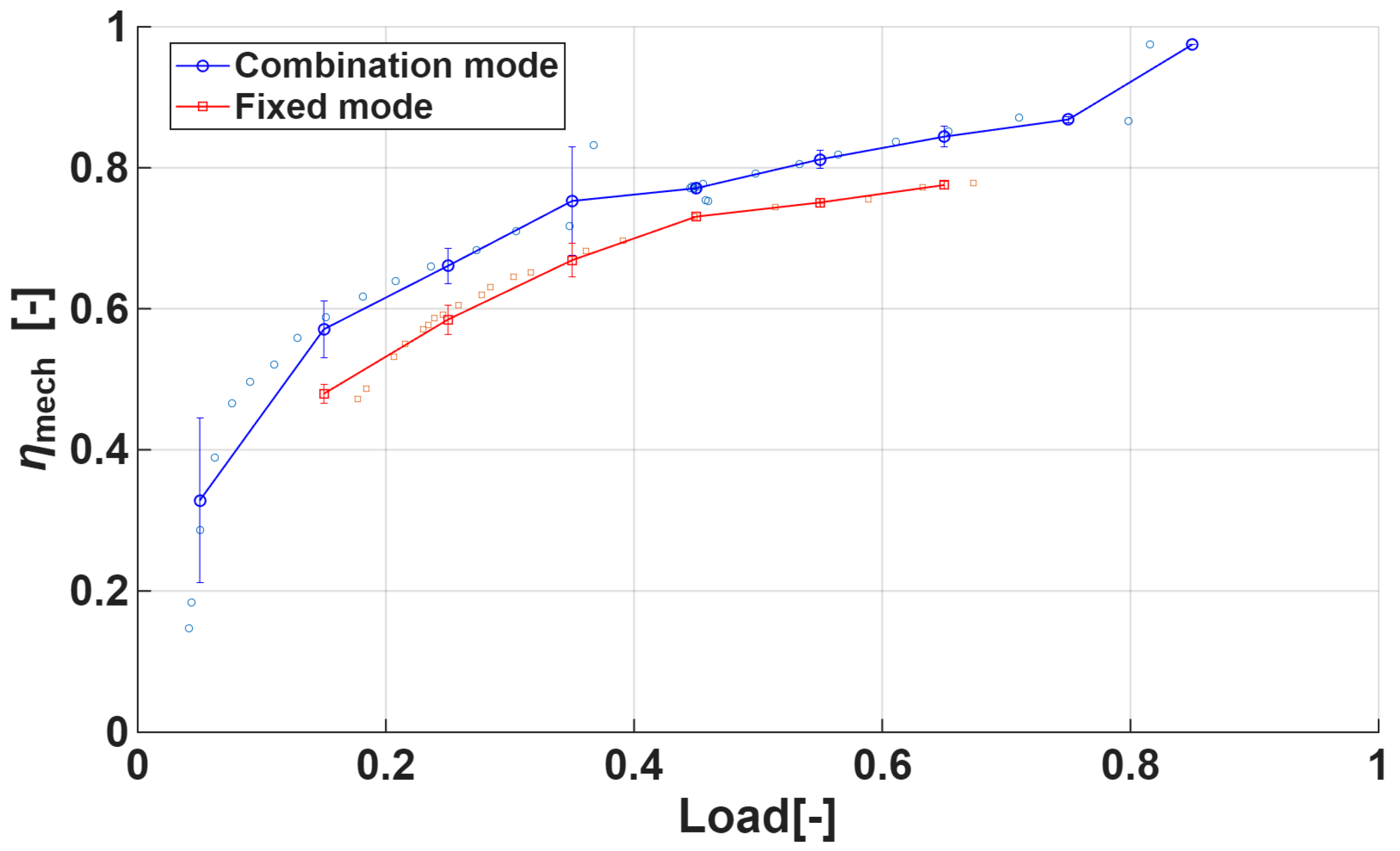
The comparison of engine mechanical efficiency (ηmech) across load ratios revealed that the Combination mode consistently achieved higher efficiency than the Fixed mode over the entire load range, as shown in Figure 7. On average, the Combination mode exceeded the Fixed mode by about 7–15 percentage points, with the performance gap gradually narrowing at higher loads. Nevertheless, across all operating conditions, the Combination mode demonstrated superior mechanical efficiency.
These findings suggest that the Combination mode is effective in minimizing mechanical losses and enabling the engine to operate closer to its optimal operating points by adjusting both RPM and propeller pitch simultaneously. In contrast, the Fixed mode, with its constant RPM constraint, shows limited adaptability to load variations, resulting in overall lower mechanical efficiency.

4.6. Analysis of the Relative Propulsive Efficiency Index (RPEI)

For a given ship, when hull form, draft, and sea conditions are assumed to remain constant, the effective horsepower (EHP) is approximately proportional to the cube of the ship speed, as expressed below [29]:
E H P   k V 3
where k is a proportional constant that can be cancelled out when the same resistance conditions are assumed across different operating modes. Accordingly, the propulsive efficiency can be expressed as Equation (3) [29]:
η p = η h u l l × η p r o p e l l e r × η s h a f t = E H P T H P × T H P D H P × D H P S H P = E H P S H P k V 3 S H P
Since k is identical under the assumption of equal resistance conditions between operating modes, propulsive efficiency is thus proportional to the cube of ship speed and inversely proportional to shaft power:
η p V 3 S H P
Because direct calculation of propulsive efficiency from operational data is difficult, this study introduces the Relative Propulsive Efficiency Index (RPEI), newly defined as:
R P E I =   V 3 S H P
For comparability across datasets, the RPEI was normalized by the overall median value, ensuring that the median equals unity:
R P E I n o r m = R P E I m e d i a n ( R P E I )
Here, the median (RPEI) denotes the cycle-weighted median evaluated on the pooled dataset (Combination and Fixed), using the number of cycles per record as weights to preserve comparability across modes.
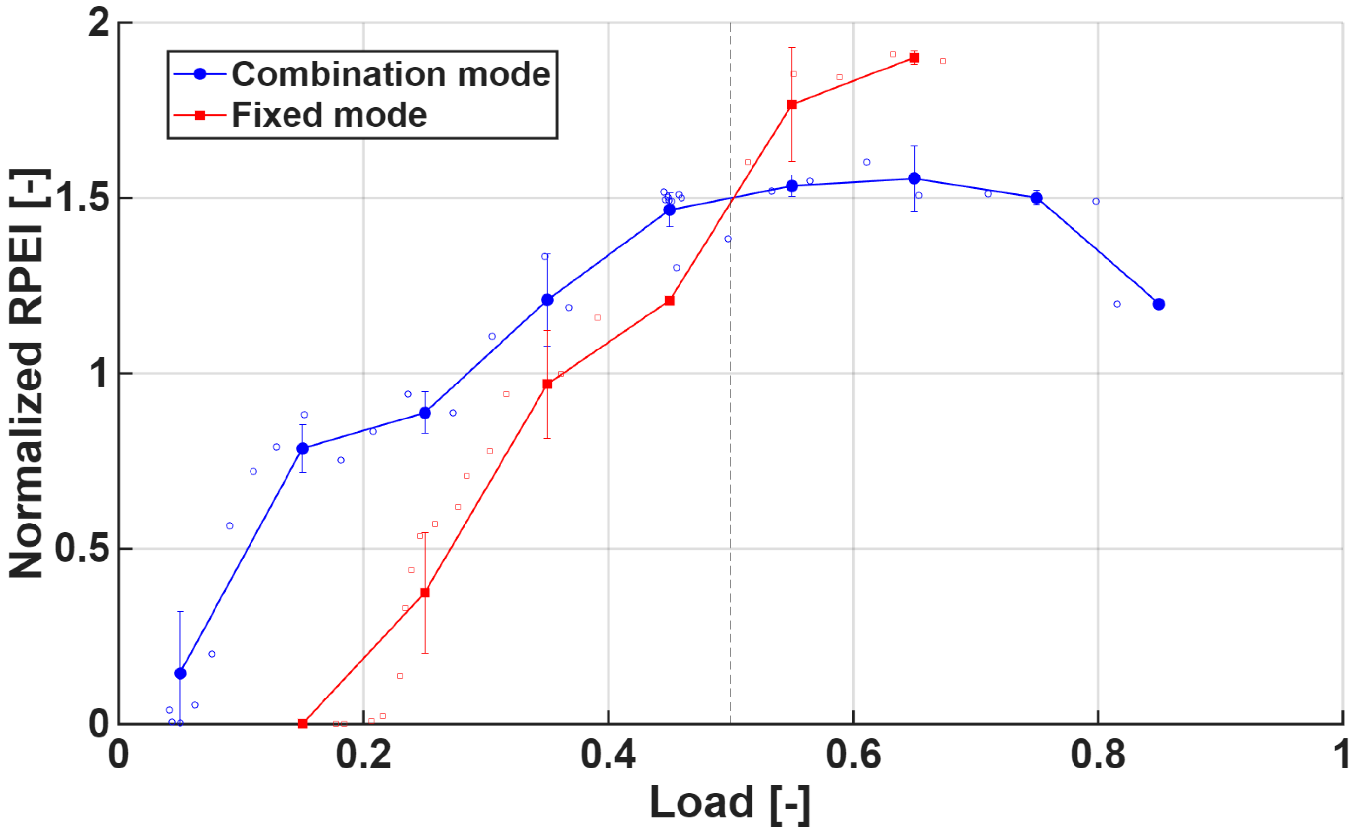
Figure 8 shows that the two operation modes exhibit distinct trends in RPEInorm as a function of load. Figure 8 displays all raw observations together with bin means and 95% CI (bin width = 0.10). A clear crossover point occurs at approximately 0.5 load, where both modes reach an RPEInorm of about 1.5. Prior to this point, the Combination mode demonstrates a relatively gradual increase in RPEInorm, rising from 0.1 to 1.5, whereas the Fixed mode shows a much steeper increase, quickly catching up to the Combination mode. Beyond the crossover, the two modes diverge again: the Combination mode maintains its RPEInorm near 1.5 and then gradually declines, while the Fixed mode continues to increase, exceeding 1.5 and reaching its peak performance at higher loads.
Therefore, the load ratio of 0.5 can be identified as a turning point: the Combination mode is more economical in low-load conditions, whereas the Fixed mode demonstrates superior propulsive efficiency under high-load conditions. It should be noted, however, that the data density around the 0.48–0.52 load range is relatively sparse, with only a few observations anchoring the crossover region. As such, the exact value of the turning point should be interpreted with caution and regarded as an indicative range rather than a precise threshold.
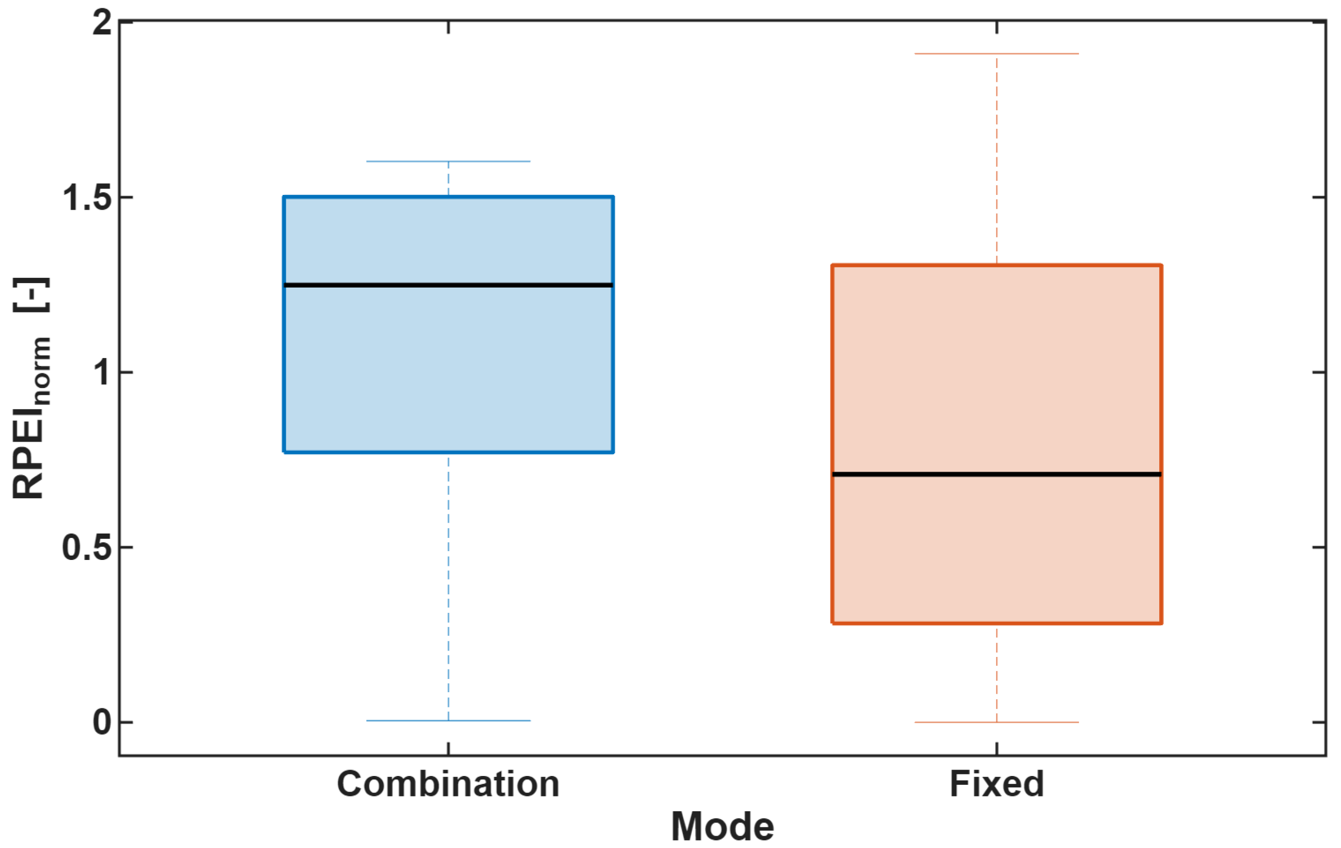
The box plot of Figure 9 illustrates the distribution of RPEInorm under the Combination and Fixed modes. The median value of the Combination mode was approximately 1.25, significantly higher than that of the Fixed mode (about 0.75). This indicates that half of the observations in the Combination mode exceeded 1.25, suggesting superior overall propulsive efficiency compared with the Fixed mode.
In terms of the interquartile range (IQR), the Combination mode exhibited a narrower and more stable spread (0.8–1.5), whereas the Fixed mode showed a wider variability (0.4–1.3). This demonstrates that under similar load conditions, efficiency variations were larger in the Fixed mode than in the Combination mode.
The whiskers also highlight distinct characteristics between the two modes. While the Combination mode had a minimum value close to zero, its maximum extended to about 1.6, reflecting low efficiency under very low load but stable high efficiency at medium to high loads. By contrast, the Fixed mode also had a minimum near zero but extended to a maximum of around 1.9, indicating the potential for achieving higher efficiency at high loads, albeit with greater variability.
In terms of symmetry and variability, the Combination mode displayed relatively balanced quartile distributions and few outliers, reflecting stable operational efficiency. The Fixed mode, however, exhibited an asymmetric distribution with a longer lower-quartile span and multiple outliers, indicating greater efficiency fluctuations with changing operating conditions.
Overall, the Combination mode provides consistently higher and more stable efficiency across the full load range, making it more suitable for low- to mid-load operations where fuel economy is critical. The Fixed mode, on the other hand, can achieve peak efficiency values up to 1.9 but frequently exhibits lower efficiency and larger variability at low loads, suggesting that it is more appropriate for operations under sufficiently high load conditions.

4.7. Overall Efficiency Proxy

By combining mechanical efficiency with the normalized propulsive efficiency, a proxy indicator was defined to approximate the relative overall efficiency of the propulsion system under actual operating conditions, as shown in Equation (7):
η o v e r a l l , p r o x y =   η m e c h   ×   R P E I n o r m
The RPEI introduced in this study serves as a physical indicator for relative comparison of propulsive performance between operating modes when direct thrust measurement is not feasible, using only ship speed and shaft power data. By normalizing RPEI to a median value of unity, differences between modes can be intuitively interpreted as deviations above or below the central reference. When combined with ηmech, the proxy overall efficiency reflects both engine-side losses and propeller performance, providing a comprehensive measure of propulsion efficiency across a wide range of operating conditions. This composite is interpreted as a first-order separable index; it aggregates engine-side efficiency (ηmech) with a propulsive proxy (RPEInorm) without asserting independence beyond the observed range. Figure 9 displays all raw observations (faint) together with bin means and 95% confidence intervals (bin width = 0.10); bins with n < 5 were omitted. Accordingly, the mid-load crossover is presented as an indicative range rather than a single point.
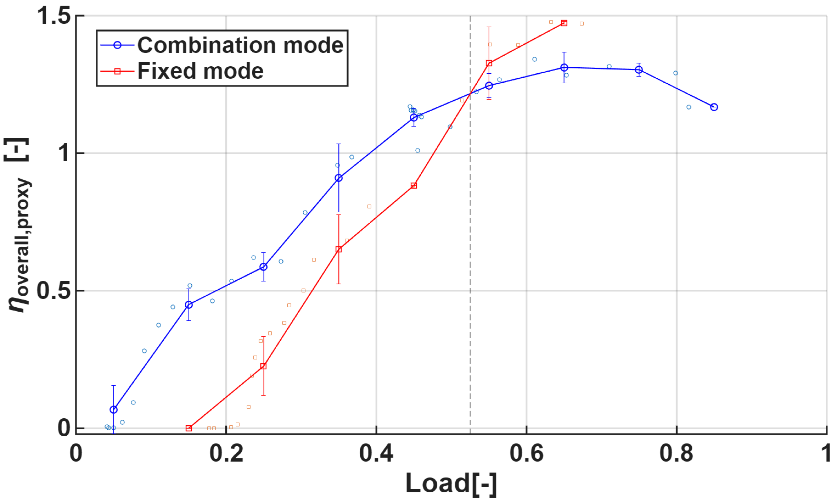
The graph in Figure 10 reveals a critical cross-over point at a load ratio of 0.525, which carries significant implications for ship propulsion system design and operational optimization. Below this threshold, the Combination mode demonstrates clear superiority. In this region, its overall proxy efficiency rises steeply from about 0.05 to 1.25, while the Fixed mode begins near zero and increases only gradually. This indicates that engine–propeller matching is more effectively optimized in the low-load range under the Combination mode.
The advantage of the Combination mode at low loads arises from its ability to adjust both engine RPM and propeller pitch simultaneously. This dual adjustment enables the engine to maintain an optimal RPM–torque balance while the propeller is set to an appropriate pitch angle, collectively achieving high mechanical and propulsive efficiency.
The cross-over point at a load ratio of 0.525 represents a critical threshold where the efficiency characteristics of the two operating modes fundamentally shift. At this point, both modes converge to an overall efficiency of approximately 1.25, reflecting a balance between their distinct optimization mechanisms. The convergence near this threshold highlights the interplay of trade-offs: in the Combination mode, mechanical efficiency remains high but its slope begins to decline, whereas in the Fixed mode, mechanical efficiency remains relatively lower but the RPEI slope rises sharply, offsetting the difference.
Beyond the 0.525 load ratio, the Fixed mode surpasses the Combination mode and sustains higher efficiency. The Fixed mode continues to rise, reaching a peak of about 1.5, while the Combination mode attains a maximum of around 1.3 before declining beyond a load ratio of 0.8. Consistent with these conventions, the crossover near ~0.5 load should be interpreted as an indicative range due to limited samples.
This reversal phenomenon is attributed to the propeller optimization effect in the high-load region. In the fixed mode, the engine speed remains constant, and as the load increases, the propeller pitch also increases, allowing the propeller to operate closer to its optimum operating condition, thereby maximizing propulsive efficiency under high-load conditions. In contrast, the combination mode is primarily focused on engine optimization, which leads to a gradual decline in propeller–engine matching efficiency in the high-load range.

5. Discussion and Conclusions

This study compared and analyzed the combination mode and fixed mode of CPP using actual ship operating data, focusing on mechanical efficiency (ηmech), propulsive efficiency (RPEInorm), and fuel consumption. The findings shed light on the dual optimization challenge in marine propulsion system design.
First, the combination mode consistently maintained higher ηmech across all load ranges by following an “engine-prioritized optimization” strategy. Particularly under low-load and low-speed conditions (ship speed < 12 knots, load < 50%), it achieved superior RPEInorm and reduced fuel consumption. This demonstrates that combination mode can enhance both economic and environmental performance in coastal navigation, port entry/exit, and low-speed cruising, where simultaneous adjustment of engine RPM and propeller pitch minimizes internal engine losses and secures favorable speed-to-power ratios.
Second, the fixed mode, following a “propeller-prioritized optimization” strategy, outperformed the combination mode in high-load and high-speed conditions. By keeping engine RPM constant and adjusting only the pitch, the fixed mode secured better RPEInorm and fuel efficiency once the load exceeded ~50% (corresponding to ~12 knots). Beyond this crossover point, the system gains more from optimizing propeller performance, even if engine efficiency is partially sacrificed. Thus, fixed mode proves more advantageous for long-distance voyages or sustained high-speed cruising. At high loads, the Fixed mode appears to operate closer to a favorable region of the propeller’s open-water characteristics; however, without open-water curves or direct thrust measurements we cannot quantify the optimal advance or thrust coefficients. We therefore treat this as indicative and plan to obtain thrust data to derive these coefficients at the crossover.
Although the analysis is based on a two-stroke diesel paired with a four-bladed CPP, the qualitative pattern—combination favored at low-speed/low-load and fixed favored at high-speed/high-load—is expected to hold for other CPP-equipped ships, while the critical speed point (crossover) is parameter-dependent. Variations in CPP geometry and control law (e.g., pitch-to-diameter ratio, expanded area ratio, blade number) and in ship condition (e.g., draft/displacement and cargo capacity) can shift the operating point and thereby shift the crossover without overturning the overall trend.
Third, the efficiency patterns of the two modes highlight the trade-off between engine and propeller optimization in propulsion system design. Combination mode ensures consistently higher mechanical efficiency but sacrifices propeller efficiency at high loads, whereas fixed mode maximizes propeller performance in heavy-load conditions at the expense of engine efficiency. This finding underscores that no single efficiency indicator is sufficient to determine the optimal design point; rather, operating profiles must guide a context-dependent optimization strategy.
Fourth, the proposed proxy overall efficiency (ηoverall,proxy), defined as the product of ηmech and RPEInorm, offers a useful integrated metric for evaluating propulsion performance. This indicator can support real-time optimization and control algorithms, enabling adaptive switching between modes based on operating conditions. Using 50% load and 12 knots as a reference point, operators could dynamically choose between combination and fixed mode to maximize overall voyage efficiency. The formulation of the RPEI in this study assumes constant hull form, draft, and sea conditions, applying the conventional relation EHP∝V3 that is widely used in efficiency analyses and preliminary power prediction methods [9,21]. In practice, however, propulsion power typically scales with V3∼4 [29], and factors such as biofouling, hull roughness, trim or draft variation, and added resistance in waves are known to increase effective resistance and required power [22,23,24]. These nonlinear effects are especially pronounced at low speeds, where viscous and wave-making components may deviate from ideal scaling. Although hull-cleaning records and sea-state logs were unavailable in the present dataset, future work should integrate such auxiliary information to conduct sensitivity analyses, thereby strengthening the robustness and real-time applicability of the RPEI.
Furthermore, we acknowledge that the proxy overall efficiency index (ηoverall,proxy) has not been directly validated against thrust-based propulsion efficiency due to the absence of propeller thrust measurements in the present dataset. While this indicator is useful as a relative measure when only engine and shaft data are available, the lack of empirical validation remains a limitation.
Finally, several limitations and directions for future research are noted. Incorporating draft, sea state, and thrust measurements will allow a more precise evaluation of true propulsive efficiency. since this analysis was limited to a single vessel and CPP system, broader studies across diverse ship types and propeller designs are necessary. To validate the applicability of the proposed real-time mode-switching strategy, follow-up studies should include simulation-based verification and full-scale sea trials.
Quantitative assessment of the crossover’s sensitivity to draft/displacement and cargo capacity—and its dependence on CPP specifications—remains a key next step for external validation across different ship types and propeller designs.
In conclusion, this study emphasizes the importance of mission- and profile-specific optimization in marine propulsion system design. By quantifying the trade-off between combination and fixed mode, it provides practical insights for enhancing both fuel economy and compliance with environmental regulations. Furthermore, the findings lay a foundation for the development of intelligent control and automation technologies for future propulsion systems. Building on these results, we now outline the principal limitations of the present work and the corresponding directions for future research.
This study adopts the constant-resistance assumption in the RPEI formulation and lacks direct thrust and open-water propeller data, so propeller operating coefficients could not be quantified. The mid-load transition (~0.5–0.525 load) is supported by relatively few observations and should be interpreted as an indicative range. The analysis is limited to a single vessel and CPP configuration. Future work will incorporate thrust sensing and open-water/CFD characterization to benchmark the proxy metric, collect denser measurements around the transition, log fouling, draft/trim, sea state and wave-added resistance for corrections, extend the analysis to multiple ship types and CPP designs, and validate a closed-loop mode-switching controller in sea trials with fuel and emissions tracking.
Author Contributions

Conceptualization, J.-W.L. and J.-U.L.; methodology, J.-W.L. and Q.D.V.; software, Q.D.V.; validation, J.-W.L., E.-S.J., J.-H.N. and J.-U.L.; formal analysis, J.-W.L. and Q.D.V.; investigation, J.-W.L., E.-S.J. and J.-H.N.; resources, J.-U.L.; data curation, E.-S.J. and J.-H.N.; writing—original draft preparation, J.-W.L.; writing—review and editing, J.-U.L., E.-S.J. and J.-H.N.; visualization, Q.D.V.; supervision, J.-U.L.; project administration, J.-U.L.; funding acquisition, J.-U.L. All authors have read and agreed to the published version of the manuscript.

Funding

This research was supported by Korea Institute of Marine Science & Technology Promotion (KIMST) funded by the Ministry of Oceans and Fisheries, grant number (RS-2022-KS221680).

Institutional Review Board Statement

Not applicable.

Informed Consent Statement

Not applicable.

Data Availability Statement

The original contributions presented in this study are included in the article. Further inquiries can be directed to the corresponding author.

Acknowledgments

During the preparation of this manuscript, the authors used ChatGPT (GPT-5) to improve clarity and readability of the text. The authors have reviewed and edited all generated content and take full responsibility for the final version of the manuscript.

Conflicts of Interest

The authors declare no conflicts of interest.

Abbreviations

The following abbreviations are used in this manuscript:
CPPControllable Pitch Propeller
RPEIRelative Propulsive Efficiency Index
IMOInternational Maritime Organization
MEPCMarine Environment Protection Committee
EEXIEnergy Efficiency Existing Ship Index
CIICarbon Intensity Indicator
GHGGreen House Gas
SEEMPShip Energy Efficiency Management Plan
FPPFixed Pitch Propeller
ALCAutomatic Load Control
ASCAutomatic Speed Control
SPESelf-Propulsion Estimation
LSLow Speed
LLLow Load
HSHigh Speed
HLHigh Load
NURBSNon-Uniform Rational B-Splines
GEPGene Expression Programming
IHPIndicated Horse Power
MCRMaximum Continuous Rating
SFCSpecific Fuel Consumption
FCFuel Consumption
SHPShaft Horse Power
BHPBrake Horse Power
SFOCspecific fuel oil consumption
EHPEffective Horse Power
THPThrust Horse Power
DHPDelivery Horse Power

Nomenclature

V Ship speed(knots)
η p Propulsive efficiency
η h u l l Hull efficiency
η p r o p e l l e r Propeller efficiency
η s h a f t Delivery efficiency
η o v e r a l l , p r o x y Proxy overall efficiency index
η m e c h Mechanical efficiency
RPEInormNormalized Relative Propulsive Efficiency Index

References

  1. Regulatory Affairs IMO Marine Environment Protection Committee (MEPC 83)-Summary Report; Lloyd’s Register: London, UK, 2025.
  2. Tian, W.; Lang, X.; Zhang, C.; Yan, S.; Li, B.; Zang, S. Optimization of Controllable-Pitch Propeller Operations for Yangtze River Sailing Ships. J. Mar. Sci. Eng. 2024, 12, 1579. [Google Scholar] [CrossRef]
  3. Ogar, O.B.; Nitonye, S.; John-Hope, I. Design Analysis and Optimal Matching of a Controllable Pitch Propeller to the Hull and Diesel Engine of a CODOG System. J. Power Energy Eng. 2018, 06, 53–74. [Google Scholar] [CrossRef]
  4. Propeller, K. A Smart Way of Using a Controllable Pitch Propeller. Kamome Propeller Co., Ltd.: Yokohama, Japan, 2019. [Google Scholar]
  5. Geertsma, R.; Negenborn, R.R.; Visser, K.; Hopman, J. Design and Control of Hybrid Power and Propulsion Systems for Smart Ships: A Review of Developments. Appl. Energy 2017, 194, 30–54. [Google Scholar] [CrossRef]
  6. Planakis, N.; Papalambrou, G.; Kyrtatos, N. Ship Energy Management System Development and Experimental Evaluation Utilizing Marine Loading Cycles Based on Machine Learning Techniques. Appl. Energy 2022, 307, 118085. [Google Scholar] [CrossRef]
  7. Geertsma, R.; Visser, K.; Negenborn, R. Adaptive Pitch Control for Ships with Diesel Mechanical and Hybrid Propulsion. Appl. Energy 2018, 228, 2490–2509. [Google Scholar] [CrossRef]
  8. Gypa, I.; Jansson, M.; Gustafsson, R.; Werner, S.; Bensow, R. Controllable-Pitch Propeller Design Process for a Wind-Powered Car-Carrier Optimising for Total Energy Consumption. Ocean Eng. 2023, 269, 113426. [Google Scholar] [CrossRef]
  9. Gao, F.; Bloch, F.; Brodtkorb, A.H. Novel Combinator Surface Concept for Efficiency Optimization of Ship Propulsion System. Ocean Eng. 2023, 280, 114489. [Google Scholar] [CrossRef]
  10. Gao, F.; Brodtkorb, A.H.; Zadeh, M.; Mo, S.M. Power Management and Optimization of Marine Hybrid Propulsion Systems: A Combinator Surface Methodology. Ocean Eng. 2024, 309, 118354. [Google Scholar] [CrossRef]
  11. Ozturk, D.; Delen, C.; Belhenniche, S.E.; Kinaci, O.K. Effect of Propeller Pitch on Ship Propulsion. Trans. Marit. Sci. 2022, 11, 133–155. [Google Scholar] [CrossRef]
  12. Moon, J.-S.; Je, M.-A.; Hwang, S.-C. A Study on Performance and Exhaust Emission Characteristics According to the Controllable Pitch Propeller Operation of Two-Stroke Diesel Engine in Sailing Condition. J. Adv. Mar. Eng. Technol. 2024, 48, 384–391. [Google Scholar] [CrossRef]
  13. Marcelo Borba Understanding Load Calculation in Thrusters: Fixed Pitch (FPT) and Controllable Pitch Propellers (CPP)—Part 2. LinkedIn 2025. Available online: https://www.linkedin.com/pulse/understanding-load-calculation-thrusters-fixed-pitch-fpt-borba-8dnlf/ (accessed on 1 September 2025).
  14. Ma, S.; Ding, Y.; Liu, G.; Sui, C.; Xiang, L. Predicting Propeller Emergence Severity in Adverse Sea Conditions: An Integrated Approach Using Stacked Machine Learning Models. Ocean Eng. 2024, 303, 117811. [Google Scholar] [CrossRef]
  15. Ortolani, F.; Santic, I.; Dubbioso, G. On the Performance of Marine Propeller in Regular Waves, Part I: Single Blade Loads in Moderate Sea States. Ocean Eng. 2024, 309, 118290. [Google Scholar] [CrossRef]
  16. Woeste, J.T.; O’Reilly, C.M.; Gouveia, R.K.; Young, Y.L. Propeller–Hull Interactions and Added Power in Head Seas. Ocean Eng. 2022, 247, 110630. [Google Scholar] [CrossRef]
  17. Wang, H.; Zheng, L.; Chen, S. Marine Propeller Optimization Based on a Novel Parametric Model. Math. Probl. Eng. 2022, 2022, 5612793. [Google Scholar] [CrossRef]
  18. Tran, T.G.; Kim, H.C. A Study on the Matching Problem of Engine, Propeller, and Ship Hull under Actual Service Conditions. Int. J. Nav. Archit. Ocean Eng. 2023, 15, 100538. [Google Scholar] [CrossRef]
  19. Halilbeşe, A.N. Investigating the Torsional Vibration Behaviour of Composite Drive Shafts in Marine Propulsion Shaft Systems. J. Nav. Archit. Mar. Technol. 2025, 43–51. [Google Scholar] [CrossRef]
  20. Olsen, A.S. Energy Coefficients for a Propeller Series. Ocean Eng. 2004, 31, 401–416. [Google Scholar] [CrossRef]
  21. Shi, W.; Stapersma, D.; Grimmelius, H. Analysis of Energy Conversion in Ship Propulsion System in Off-Design Operation Conditions. WIT Trans. Ecol. Environ. 2009, 121. [Google Scholar]
  22. Schultz, M.P. Effects of Coating Roughness and Biofouling on Ship Resistance and Powering. Biofouling 2007, 23, 331–341. [Google Scholar] [CrossRef]
  23. Song, S.; Demirel, Y.K.; Muscat-Fenech, C.D.M.; Tezdogan, T.; Atlar, M. Fouling Effect on the Resistance of Different Ship Types. Ocean Eng. 2020, 216, 107736. [Google Scholar] [CrossRef]
  24. Liu, S.; Papanikolaou, A. Fast Approach to the Estimation of the Added Resistance of Ships in Head Waves. Ocean Eng. 2016, 112, 211–225. [Google Scholar] [CrossRef]
  25. Chapter 5—Powering. In The Maritime Engineering Reference Book; Molland, A.F., Ed.; Butterworth-Heinemann: Oxford, UK, 2008; pp. 181–343. ISBN 978-0-7506-8987-8. [Google Scholar]
  26. Geertsma, R.D.; Negenborn, R.R.; Visser, K.; Loonstijn, M.A.; Hopman, J.J. Pitch Control for Ships with Diesel Mechanical and Hybrid Propulsion: Modelling, Validation and Performance Quantification. Appl. Energy 2017, 206, 1609–1631. [Google Scholar] [CrossRef]
  27. International Maritime Organization. Fourth IMO Greenhouse Gas Study (2020); International Maritime Organization: London, UK, 2020. [Google Scholar]
  28. Lee, J.-U.; Lee, W.-J.; Jeong, E.-S.; Noh, J.-H.; Kim, J.-S.; Lee, J.-W. Algorithm for Monitoring Emissions Based on Actual Speed of Ships Participating in the Korean Vessel Speed Reduction Program. Energies 2022, 15, 9555. [Google Scholar] [CrossRef]
  29. MAN Energy Solutions. Basic Pricciples of Ship Propulsion; MAN Energy Solutions: Bavaria, Germany.
Figure 1. Overall structure of the research methodology.
Applsci 15 10435 g001
Figure 2. Schematic diagram of measurement system.
Applsci 15 10435 g002
Figure 3. Indicated and brake power versus ship speed under Combination and Fixed CPP operating modes.
Applsci 15 10435 g003
Figure 4. Relationship Between Ship Speed and Propulsive Load for Combination and Fixed Modes.
Applsci 15 10435 g004
Figure 5. Propeller Pitch Versus Torque on a Logarithmic Scale for Combination and Fixed Modes, Colored by RPM.
Applsci 15 10435 g005
Figure 6. Relationship Between Ship Speed and Fuel Consumption for Combination and Fixed Modes.
Applsci 15 10435 g006
Figure 7. Mechanical efficiency as a function of engine load in Combination and Fixed CPP modes.
Applsci 15 10435 g007
Figure 8. Normalized RPEI as a function of engine load in Combination and Fixed modes.
Applsci 15 10435 g008
Figure 9. Box plot comparison of RPEInorm between Combination and Fixed CPP operation modes.
Applsci 15 10435 g009
Figure 10. Proxy overall efficiency (ηoverall,proxy) versus load under Combination and Fixed CPP operating modes.
Applsci 15 10435 g010
Table 1. Comparison of related studies and this study’s novelty and scope.
StudyScope/MethodKey FindingsRelevance to This Study
Tian et al. (2024) JMSE [2]Yangtze River vessels; CPP operation optimization (pitch–RPM scheduling).Shows that coordinated pitch/RPM optimization can improve energy efficiency under riverine conditions.Aligns with this study’s focus on operation-dependent efficiency and mode selection logic.
Ogar et al. (2018) JPEE [3]CODOG system; design analysis and optimal matching of CPP to hull and diesel engine.Presents procedure to match propeller, engine curves and hull resistance for optimal performance.Supports analysis of engine–propeller interaction underlying Combination vs. Fixed comparisons.
Geertsma et al. (2018) Applied Energy [7]Adaptive pitch control for diesel-mechanical/hybrid propulsion.Demonstrates fuel and emission reductions via adaptive pitch strategies across operating speeds.Corroborates efficiency gains achievable by active pitch control strategies.
Gypa et al. (2023) Ocean Engineering [8]CPP design process for a wind-assisted car carrier; total energy optimization.CPP structures design decisions around total energy consumption objectives.Links design-stage choices to operation-stage efficiency indicators used here.
Gao et al. (2023) Ocean Engineering [9]‘Combinator surface’ concept: selecting optimal RPM-pitch-speed operating points.Extends classic combinator curves to a surface for efficiency optimization across regimes.Conceptually consistent with crossover analysis (~0.5–0.525 load) and mode switching.
Öztürk et al. (2022) Trans. Marit. Sci. [11]Effect of propeller pitch on ship propulsion using model/ship data.Optimal pitch depends on speed; increasing pitch is not universally beneficial.Supports pitch-dependence of efficiency trends seen in this dataset.
Schultz, M.P. (2007) Biofouling [22]Coating roughness & biofouling effects on resistance and powering.Reports notable power penalties; even light slim can increase frictional resistance noticeably.Frame resistance variability affecting RPEI and proxy efficiency interpretation.
Song et al. (2020) Ocean Engineering [23]Fouling effect on resistance across different ship types (experimental/numerical).Resistance increase varies with ship type and fouling condition.Supports discussion on hull-condition sensitivity of propulsive indicators.
Liu & Papanikolaou (2016) Ocean Engineering [24]Fast estimation of added resistance in head waves (semi-empirical).Provides engineering formulas to quantify wave-induced resistance additions.Motivates adding sea-state effects in future sensitivity analyses of RPEI/proxy metric.
This studyFull-scale operational data; CPP Combination vs. Fixed comparison.Identifies crossover at 0.5–0.525 load; introduces η o v e r a l l , p r o x y Provides empirical, integrated assessment and strategy for adaptive mode switching.
Table 2. Specifications of propulsion system.
ParameterDescriptionParameterDescription
Main engine typeHYUNDAI-MAN B&W 6S40ME-B9.5-LP SCRPropeller shaft part 1330 mm × 1494 mm
(Inner Dia. 115 mm)
Max. continuous output (Full pitch)6618 kWPropeller shaft part 2380 mm × 3290 mm
(Inner Dia. 115 mm)
Max. continuous output (Zero pitch)726.4 kWPropeller shaft part 3398 mm × 1876 mm
(Inner Dia. 115 mm)
Revolution146 rpmNo. 1 Intermediate shaftΦ330 mm × 11,000 mm
Cylinder bore400 mmNo. 2 Intermediate shaftΦ330 mm × 11,000 mm
Stroke1770 mmNo. 3 Intermediate shaftΦ330 mm × 9781 mm
Number of cylinders6Number of propeller blades4 ea
Pmax185 barPropeller mass8346 kg
Mean indicated pressure21.38 barPropeller diameter4.0 m
Table 3. Definitions and applications of performance indicators for evaluating CPP operating modes.
IndicatorDefinitionMeaningApplication
LoadIHP/MCRRelative engine load levelClassification of operating conditions
SFCg/kWh (baseline:173.4)Fuel efficiency per unit powerBasis for fuel consumption analysis
FC(SFC × IHP) (ton/h)Fuel consumption per hourEvaluation of operational economy
ηmechSHP/IHPMechanical efficiency Comparison of engine performance
RPEInorm(V3/SHP), normalizedRelative propulsive efficiency indexComparison of propulsive performance by mode
ηoverall,proxyηmech × RPEInormIntegrated efficiency index combining engine and propellerAssessment of overall propulsion efficiency
Disclaimer/Publisher’s Note: The statements, opinions and data contained in all publications are solely those of the individual author(s) and contributor(s) and not of MDPI and/or the editor(s). MDPI and/or the editor(s) disclaim responsibility for any injury to people or property resulting from any ideas, methods, instructions or products referred to in the content.