Article

Modelling Magnetisation and Transport AC Loss of HTS Tapes near Ferromagnetic Materials Using an Integral Equation Method

1
Research Centre for Electric Vehicles and Department of Electrical and Electronic Engineering, The Hong Kong Polytechnic University, Hung Hom, Kowloon, Hong Kong SAR, China
2
Institute for Technical Physics (ITEP), Karlsruhe Institute of Technology (KIT), 76131 Karlsruhe, Germany
*
Authors to whom correspondence should be addressed.
Appl. Sci. 2025, 15(19), 10411; https://doi.org/10.3390/app151910411
Submission received: 26 August 2025 / Revised: 19 September 2025 / Accepted: 22 September 2025 / Published: 25 September 2025
(This article belongs to the Special Issue Applied Superconductivity: Material, Design, and Application)

Abstract

The integral equation formulation of Maxwell’s equations proposed by Brandt provides an alternative to the H and T-A formulations for modelling high-temperature superconducting (HTS) tapes. A modified version of Brandt’s method in the literature models ferromagnetic domains near the tapes by considering the ferromagnetic domains as equivalent surface current. This paper extends this method by including the effect of external magnetic field acting on the ferromagnetic and HTS domains. The proposed method is used on a benchmark problem, which considers an HTS tape with a ferromagnetic substrate under an external time-varying magnetic field. The results agree closely (error in average ac loss less than 3%) with the widely-used T-A formulation implemented in COMSOL down to 2 mT. In addition, the proposed method is also applied to HTS tapes carrying transport ac current in a slot of a machine’s stator iron core, and HTS tapes in a stator iron slot in a machine under working conditions. It is found that ac loss calculated by the proposed method increases as the discretization size of the ferromagnetic material’s boundary decreases, and overshoots the value calculated by the T-A formulation in COMSOL when using very fine discretization.

1. Introduction

High-temperature superconducting (HTS) tapes and bulks can be used in a variety of power applications [1], such as high-field magnets [2], NMR magnets [3], electrical machines [4], fusion magnets [5], particle accelerators [6], fault current limiters [7], electric power cables [8], and energy storage [9]. Whilst superconductors transport dc current without loss, they dissipate ac loss when they are placed under a time-varying magnetic field or when they carry an ac current. Accurate and fast modelling of ac loss is important when designing superconducting systems to ensure sufficient cooling is provided to prevent quenching, and to assess the efficiency of the system. This paper considers, in particular, the hysteresis loss (which we will simply refer to as ‘loss’) in superconductors.
To model loss in superconductors, the finite element method (FEM) is frequently used in order to model complicated geometries and interaction between superconductors and other components. Different formulations of Maxwell’s equations have been used, but the H [10,11,12] and T-A [13,14,15] formulations have become widespread and can be conveniently implemented in the commercial software COMSOL Multiphysics. On the other hand, Brandt [16] provided an alternative that modelled the dynamics of a superconductor via time-integration of a relatively simple integral equation, and current density J was the variable being solved for. Brandt’s method does not mesh the air surrounding the superconductor. Brandt’s method and its modified versions have been investigated by various authors, many of whom considered superconductors in vacuum and not near any ferromagnetic material [17,18,19,20,21,22,23,24,25,26,27,28,29,30,31,32,33,34,35,36,37,38]. Otten and Grilli [30] provided detailed derivation of the method for a thin strip, a rectangular wire and a cylindrical bulk. Musso et al. [32] used Brandt’s method on both superconducting and non-superconducting layers in a composite tape to evaluate the total loss. Lai and Gu [33] developed Brandt’s method for multiple superconducting tapes, and the method was reported to be at least 4.4 times faster than the H and T-A formulations implemented in COMSOL in the examples in the paper. The paper named the method the J model since the method solved for current density J in an ordinary differential equation. Kang and Wang [35] developed a homogenised version of the J model and modelled multiple HTS tapes as a homogenised anisotropic bulk. Further, a 3D version of J model was also developed to model a conductor on round core (CORC) cable in [34]. Brandt’s method is also extended to model, in 2D, tapes that are connected in parallel [37]. Brandt’s method has been used to model a Roebel cable [31], tapes in radial [36] and linear [38] electrical machines, and magnetisation of an HTS bulk [29].
However, in many applications, superconductors are located near ferromagnetic materials, e.g., in electrical machines/proposed magnetic gears with iron core [39,40,41,42,43]. Thus, there is a need to develop Brandt’s method so that iron can be modelled as well. Some authors have extended Brandt’s method to model ferromagnetic materials near superconductors. Recently, Zhu et al. [44] coupled the J model with the magnetic equivalent circuit (MEC) to model HTS tapes near ferromagnetic materials: the MEC calculated the magnetic field experienced in the tapes’ area, which was fed into the J model, whilst the J model calculated the current distribution in the tapes and fed this into the MEC model. Statra et al. [45] modelled iron (of constant relative permeability μ r ) directly in a modified Brandt method by considering it as an equivalent surface current. The same authors [46] further developed the model by considering interface current density in discretized elements in the ferromagnetic domain in order to model variation of μ r ( H ) with magnetic flux intensity H.
This paper’s main contribution is to extend the work by Statra et al. [45] by considering the effect of external magnetic field on HTS tapes and iron, thus allowing magnetisation loss to be calculated. We apply the method to Benchmark #2 on https://htsmodelling.com/ [47], which considers an HTS tape (consisting of an HTS layer and a rectangular ferromagnetic substrate) subject to a time-varying external magnetic field. Then, we apply the method to HTS tapes carrying a transport ac current in a slot in a machine’s stator iron core. Finally, we consider HTS tapes in a stator iron slot in a machine under working conditions of the machine, with other stator coils carrying ac current and with the rotor (which has permanent magnets (PMs) on it) rotating. Statra et al. [45] also considered an example of a stack of superconducting tapes near a rectangular block of ferromagnetic part, but this paper further considers the example of HTS tapes in the stator of an electrical machine.
The focus of the paper is to check whether the modified Brandt method can give results that agree with COMSOL (version 6.2 used in this paper), rather than a comparison in time taken by the Brandt method and COMSOL. This is because for fair comparison between the two methods, both COMSOL settings and the Matlab code implementing the modified Brandt method should be optimised, and yet the optimisation of code and the larger number of settings in COMSOL is beyond the scope of this paper. Brandt’s method has the advantage that it can potentially be implemented in non-proprietary software, thus providing an alternative to COMSOL. Whilst this paper uses Matlab and its built-in ordinary differential equation solver ode15s, the method presented in this paper can be coded in other languages, and alternative solvers have been used for the Brandt method in the language Julia [30]. In terms of time taken for computation, it has been reported in the literature [48,49] that, for small problems (like those presented in this paper), the time taken by a variation of the Brandt method (and by extension the original Brandt method) is less than that by FEM in COMSOL. However, as the number of elements n in the superconductor domain increases, the time taken by the modified Brandt method increases as n to the power of x where the exponent x is larger for the modified Brandt method than FEM, meaning that for a large number of elements, FEM would be faster than the modified Brandt method.
This rest of this paper is organised as follows. Section 2 introduces the problem set-up that this paper aims to solve. Section 3 details the modified Brandt method that considers the effect of external magnetic field. Section 4 shows the results of Benchmark #2 and the cases of HTS tapes in a stator slot of a machine. We conclude in Section 5.

2. Problem Set-Up

This paper considers the situation of multiple superconducting tapes in air carrying a transport current into the page whilst being subject to an externally applied, in-plane magnetic flux density B a ( x , y , t ) that is time-varying and spatially non-uniform. The tapes are located near a ferromagnetic material, which is subject to an externally applied, in-plane magnetic flux density B 0 ( t ) that is time-varying and spatially uniform. The general geometry modelled is illustrated in Figure 1, but specific geometries modelled in this paper are described in Figure 2 and Figure 3a.
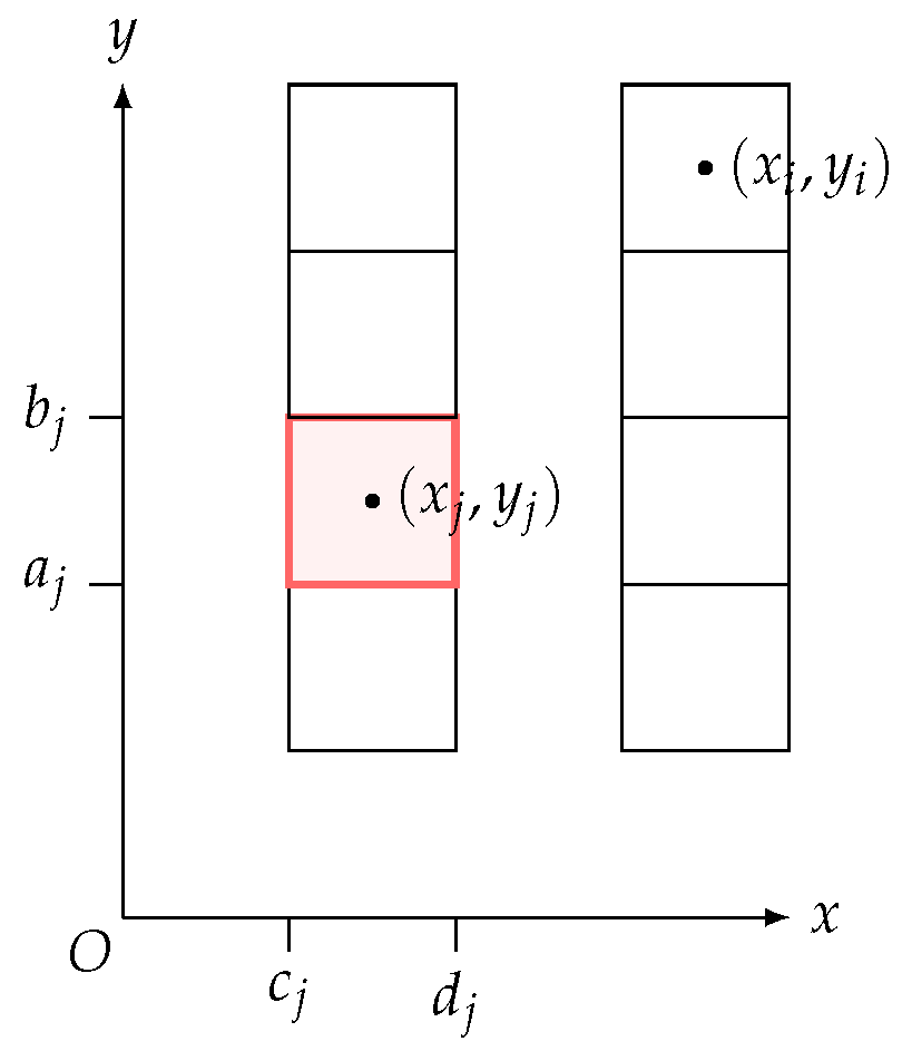
The geometry is 2D on the x-y plane. Let the superconducting domain be S, and the iron domain’s boundary be Γ . The iron domain may have more than one closed boundary (e.g., an annulus, which has an inner and outer circumference), and in such cases all boundaries are included in Γ . The iron domain has a constant relative permeability μ r . The domain S is discretized into N e elements Δ S i , i = 1 , 2 , N e . The centre of each element Δ S i is r i = ( x i , y i ) . The superconducting layer in each tape is discretized into a single layer of 2D elements, with each element having a thickness equal to the thickness of the superconducting layer, as shown in Figure 4. Γ is discretized into n f elements Δ Γ i , i = 1 , 2 , n f . The centre of each element Δ Γ i is also denoted r i (whether r i refers to a point on Γ or on S will be clear based on context). On each element Δ Γ i on contour Γ , the surface current density is assumed to be uniform and is denoted k ( r i ) .
The superconductor domain is subject to an externally applied magnetic flux density B a ( x , y , t ) = B a , x x ^ + B a , y y ^ . On the other hand, the iron domain is subject to an externally applied magnetic flux density B 0 ( t ) = μ 0 H 0 ( t ) where the externally applied magnetic field strength H 0 ( t ) = H 0 , x x ^ + H 0 , y y ^ . Under some circumstances, B a and B 0 are the same, e.g., in Section 4.1, but there are situations where they are different, e.g., in Section 4.3.

3. Formulation

The formulation presented in this section follows that in [45], except with the addition of terms involving H 0 and B a .

3.1. Representation of Iron Domain as Surface Current Density

In the iron domain, the magnetic flux density B = μ 0 μ r H = μ 0 ( H + M ) , where M is the magnetisation and H is the magnetic field strength. Eliminating H , we obtain the following:
M = μ r 1 μ 0 μ r B .
The iron domain is equivalent to a domain with a bound volume current density J b = × M and a bound surface current density k = M × n [50], where n is the outward unit vector normal to the surface. Since we consider iron to be a linear material with M H , × M × H = 0 according to Ampere’s law if we neglect the eddy current density in iron [45]. Thus, the iron domain is represented as a domain with zero J b and a bound surface current density:
k = M × n = μ r 1 μ 0 μ r B × n ,
where B = B ( r Γ ) is the magnetic flux density at a position on the contour just inside the iron. Let B ( r Γ + ) and B ( r Γ ) denote the magnetic flux density at a position on the contour just outside and inside the iron domain, respectively.

3.2. Equations for Superconducting Domain S

From Ampere’s law, J = × H , and using B = μ 0 H in S and × A = B , under Coulomb gauge ( · A = 0 ), we obtain the following:
μ 0 J = 2 A .
The magnetic vector potential A at a point in the superconductor is due to A J produced by the current in S and Γ , and the background field A a (where B a = × A a ):
A = A J + A a .
Substituting into (3) and noting 2 A a = 0 , even for a spatially non-uniform background field [36], we obtain the following:
2 A J = μ 0 J .
Due to the 2D geometry, we obtain the following:
A , J , k , E = { A ( x , y , t ) , J ( x , y , t ) , k ( x , y , t ) , E ( x , y , t ) } z ^ ,
where E is the electric field intensity. Thus, (5) becomes:
2 A J = μ 0 J .
The Green function solution to this Poisson equation in infinite volume (area for 2D geometry) takes into account all current sources (in S and on Γ ):
A J ( r ) = μ 0 Γ k ( r ) Q ( r , r ) d r + μ 0 S J ( r ) Q ( r , r ) d 2 r ,
where Q is the Green function for 2D (with negative sign due to negative sign in (7)):
Q ( r , r ) = 1 2 π ln | r r | .
For r S , the magnetic flux density B = × A J + B a , and the x and y components are as follows:
B x ( r ) = A J y + B a , x ( r ) = μ 0 Γ k ( r ) Q y ( r , r ) d r + μ 0 S J ( r ) Q y ( r , r ) d 2 r + B a , x ( r )
B y ( r ) = A J x + B a , y ( r ) = μ 0 Γ k ( r ) Q x ( r , r ) d r μ 0 S J ( r ) Q x ( r , r ) d 2 r + B a , y ( r )

3.3. Expression for k

At the interface between two material space, ( H 1 H 2 ) × n 12 = k , where k is the surface current density at the interface, n 12 is the unit vector normal to surface directed from region 1 to region 2, and H 1 and H 2 are H in region 1 and 2, respectively. Thus, at the interface between iron and air, we obtain the following:
( B ( r Γ + ) B ( r Γ ) ) × n = μ 0 k ,
where r Γ + and r Γ are points near Γ in air and iron regions, respectively, and n points from iron to air. Substituting B ( r Γ ) × n = μ 0 μ r / ( μ r 1 ) k from (2), and rearranging, we obtain the following:
B ( r Γ + ) × n = μ 0 μ r 1 k .
From reference in [45], consider a point r on Γ with outward normal unit vector n ( r ) (pointing away from iron), as follows:
n × B ( r Γ ± ) = ± μ 0 2 k ( r ) + C ,
where C = C z are the common terms that come from the contributions to B at evaluation point r on Γ other than the k ( r ) at evaluation point on Γ ; ± ( μ 0 / 2 ) k ( r ) is the contribution due to k at evaluation point on the boundary. Note that (14) satisfies (12). The common terms are as follows:
C = n × B x B y 0 = n x B y n y B x z ^ ,
where B x and B y are the components of magnetic flux density at the evaluation point r Γ due to currents other than k ( r ) at the evaluation point on Γ :
B x ( r ) μ 0 = Γ ( r r ) k ( r ) Q y d r + S J ( r ) Q y d 2 r + H 0 , x
B y ( r ) μ 0 = Γ ( r r ) k ( r ) Q x d r S J ( r ) Q x d 2 r + H 0 , y .
By equating the expressions for B ( r Γ + ) × n in (13) and (14) and rearranging, we obtain the following:
k = 2 μ r 1 μ 0 μ r + 1 n x B y n y B x z ^ .
In our 2D geometry, at a discretized point r i on Γ , we obtain the following:
k ( r i ) = 2 ( μ r 1 ) μ r + 1 [ j = 1 ( j i ) n f n x ( r i ) Δ Γ j Q x ( r i , r ) d r + n y ( r i ) Δ Γ j Q y ( r i , r ) d r k ( r j ) + j = 1 N n x ( r i ) Δ S j Q x ( r i , r ) d 2 r + n y ( r i ) Δ S j Q y ( r i , r ) d 2 r J ( r j ) n x ( r i ) H 0 , y + n y ( r i ) H 0 , x ] .
Collecting Equation (19) for all r i , i = 1 , 2 , , n f on Γ , we obtain the following:
k = M F F = k _ + M F S = J _ + M F = H 0 I = + M F F = k _ = M F S = J _ + M F = H 0 k _ = I = + M F F = 1 M F S = J _ + M F = H 0 ,
where J _ is a N e   × 1 vector with elements [ J ̲ ] i = J ( r i ) ; k _ is a n f   × 1 vector with elements [ k ̲ ] i = k ( Γ i ) ; H 0 = [ H 0 , x , H 0 , y ] ; I = is a n f × n f identity matrix; M F F = is a n f × n f matrix, M F S = is a n f × N matrix, and M F = is a n f × 2 matrix with the following elements:
M F F = i j = 2 ( μ r 1 ) μ r + 1 n x ( r i ) Δ Γ j ( i j ) Q x ( r i , r ) d r + n y ( r i ) Δ Γ j ( i j ) Q y ( r i , r ) d r
M F S = i j = 2 ( μ r 1 ) μ r + 1 n x ( r i ) Δ S j Q x ( r i , r ) d 2 r + n y ( r i ) Δ S j Q y ( r i , r ) d 2 r
M F = i , 1 = n y ( r i ) 2 ( μ r 1 ) μ r + 1
M F = i , 2 = n x ( r i ) 2 ( μ r 1 ) μ r + 1 .  
Note that as with our previous article [36], underlines denote vectors that consist of scalar quantities evaluated at different positions/turns; whilst double underlines denote matrices. Bold quantities are vectors whose components corresponds to components in different spatial directions. All quantities are real in this paper.

3.4. Further Discretization

Similar to how k is evaluated at discretized points on Γ in (19), from (8)–(11), A, B x and B y can be evaluated at discretized locations in S as follows:
A ( r i ) = μ 0 j = 1 n f k ( r j ) Δ Γ j Q ( r i , r ) d r + μ 0 j = 1 N J ( r j ) Δ S j Q ( r i , r ) d 2 r + A a ( r i )
B x ( r i ) = μ 0 j = 1 n f k ( r j ) Δ Γ j Q y ( r i , r ) d r + μ 0 j = 1 N e J ( r j ) Δ S j Q y ( r i , r ) d 2 r + B a , x ( r i )
B y ( r i ) = μ 0 j = 1 n f k ( r j ) Δ Γ j Q x ( r i , r ) d r μ 0 j = 1 N e J ( r j ) Δ S j Q x ( r i , r ) d 2 r + B a , y ( r i ) .
Collecting equations for r i , i = 1 , , N e in S, we obtain the following:
A _ = L S F = k _ + L S S = J _ + A a _
B x _ = M B x S F = k _ + M B x S S = J _ + B a , y _
B y _ = M B y S F = k _ + M B y S S = J _ + B a , y _ ,
where A _ , B x _ , B y _ , A a _ , B x , a _ , and B y , a _ are N e   × 1 vectors with elements A ̲ i = A ( r i ) , B x ̲ i = B x ( r i ) , B y ̲ i = B y ( r i ) , A a ̲ i = A a ( r i ) , B a , x ̲ i = B a , x ( r i ) , and B a , y ̲ i = B a , y ( r i ) , respectively.
The matrices have the following elements:
L S F = i j = μ 0 Δ Γ j Q ( r i , r ) d r
L S S = i j = μ 0 Δ S j Q ( r i , r ) d 2 r
M B x S F = i j = μ 0 Δ Γ j Q y ( r i , r ) d r
M B x S S = i j = μ 0 Δ S j Q y ( r i , r ) d 2 r
M B y S F = i j = μ 0 Δ Γ j Q x ( r i , r ) d r
M B y S S = i j = μ 0 Δ S j Q x ( r i , r ) d 2 r .
The closed forms for the line and area integrals in (21), (22), (31)–(36) are given in Appendix A for the general case when Δ Γ i and boundaries of Δ S i are not necessarily parallel to the x or y axes (reference [45] only provided closed forms for the case when Δ Γ j and boundaries of Δ S i are parallel to the x or y axes). Note r i Γ in (21)–(24), and r i S in (31)–(36).

3.5. Overall Ordinary Differential Equation

Recalling the definition of the electric scalar potential in time-varying field E + A t = ϕ and collecting equations for all r i S , we obtain the following:
t A _ + E _ + ϕ z _ = 0 ,
where A _ , E _ , ϕ z _ are N e × 1 vectors with elements [ A ̲ ] i = A ( r i ) , [ E ̲ ] i = E ( r i ) , [ ϕ z ̲ ] i = ϕ ( r i ) z . As mentioned in [30], ϕ ( r i ) z = ϕ ( Ω j ) z for all points r i in HTS layer area Ω j of tape j. Similar to [30], the ϕ ( Ω j ) z for HTS layer j can be governed by the following feedback control to force transport current through the HTS layer to be the value set:
ϕ z ̲ = γ S = ( J _ J S _ ) ,
where S = is N e × N e matrix with elements S = i j = area of element Δ S j if Δ S j   and Δ S i are in the same HTS layer and = 0 otherwise. J S _ is N e × 1 vector with the following elements:
J S _ i = set transport current for HTS layer that Δ S i belongs to HTS layer thickness × HTS layer width .
Substitute (38) and (28) into (37) as follows:
t L S F = k _ + L S S = J _ + A a _ + E _ + γ S = ( J _ J S _ ) = 0 .
Substitute (20) as follows:
K F e = J _ ˙ = E _ A a _ ˙ L S F = I = + M F F = 1 M F = H ˙ 0 γ S = ( J _ J S _ ) ,
where K F e = = L S F = I = + M F F = 1 M F S = + L S S = and is time independent and is equal to L S S = if μ r = 1 . The ordinary differential Equation (40) is implemented by Matlab ode15s.
E _ consists of E ( r i ) in each element, where E ( r i ) is a function of J ( r i ) according to the non-linear E J power law as follows:
E = E c | J J c | n J | J | ,
where J c is the critical current density and is taken as a constant in simulations in the rest of this paper. However, J c can also be dependent on components of B parallel and perpendicular to the tape.

4. Results

4.1. Benchmark #2

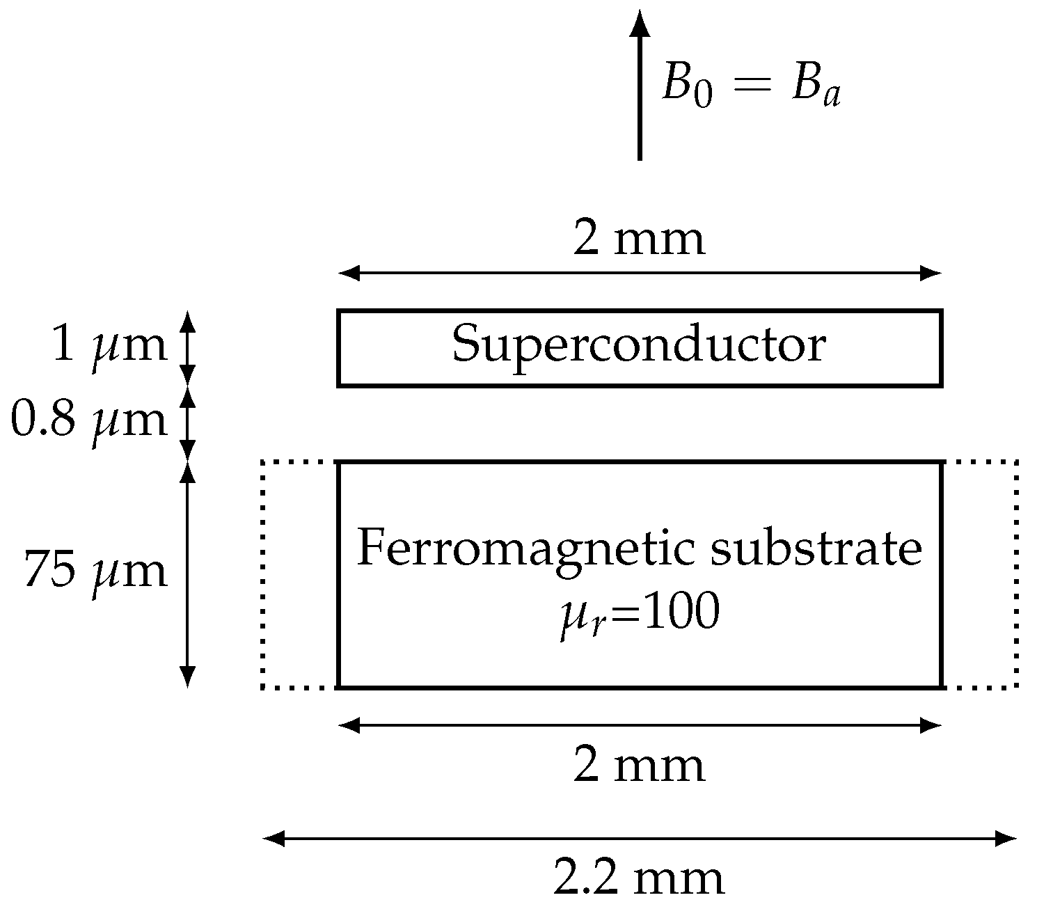
The modified Brandt method in Section 3 is applied to the Benchmark #2 problem in [47]. The problem considers an HTS tape with a magnetic substrate subject to a time-varying external field. The external magnetic field is at 50 Hz and has an amplitude of B ext , 0 ; it is directed perpendicularly to the tape’s face and is assumed to vary sinusoidally in this paper. The HTS layer is 2 mm wide and has critical current 50 A; the magnetic substrate, which is of constant μ r = 100 , is either 2 mm or 2.2 mm wide. The problem is illustrated in Figure 2.
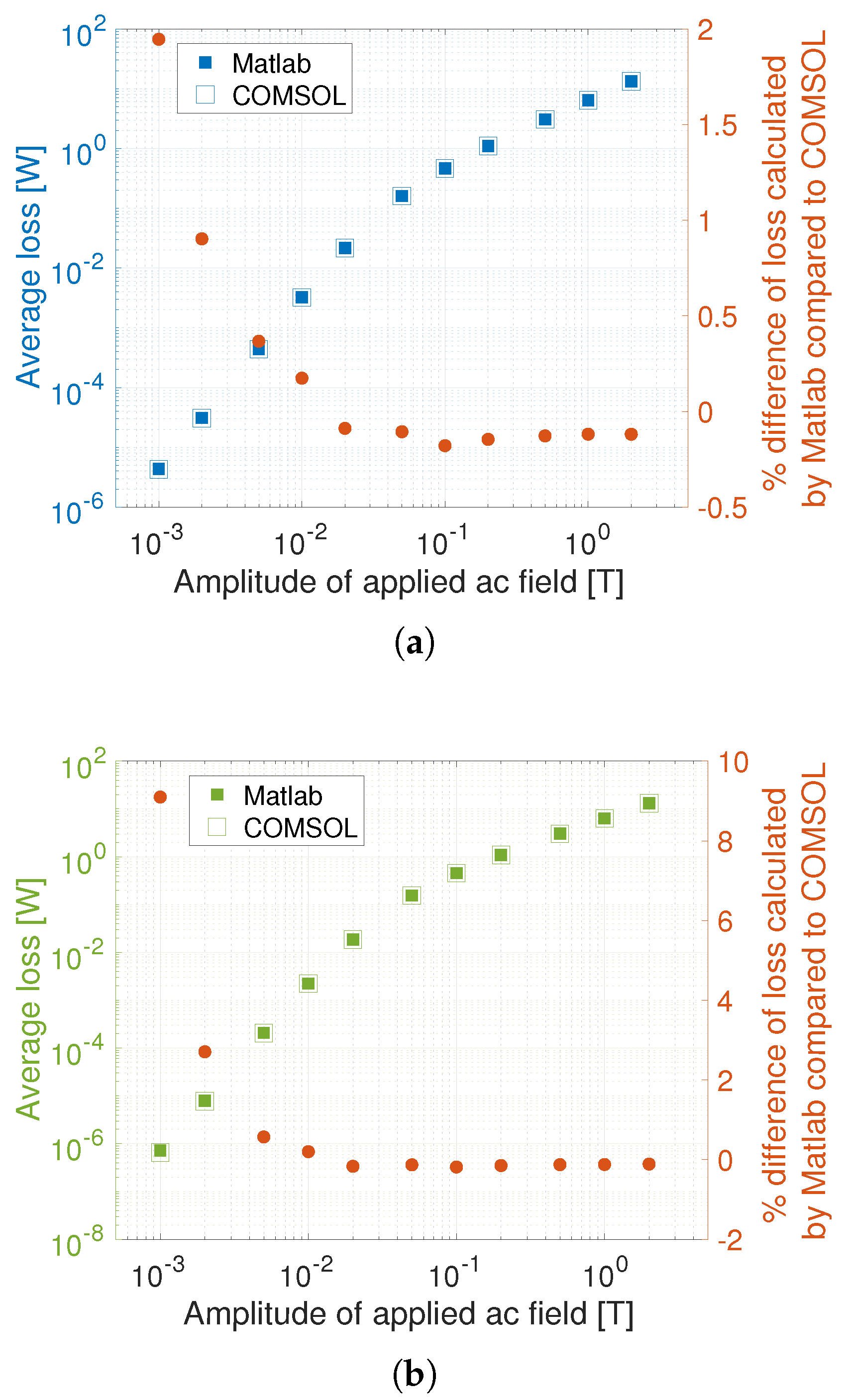
The tape is simulated via the T-A formulation in COMSOL as well as the modified Brandt method in Matlab. The external magnetic field has y-component B a , y = μ 0 H 0 , y = B ext , 0 sin ( 2 π f t ) , where f = 50 Hz. The amplitude B ext , 0 is varied from 1 mT to 2 T. For small amplitudes of 10 mT or less, a finer mesh is used for the tape with more than 1000 elements (mesh is slightly different between 2 mm and 2.2 mm substrate), otherwise the tape is discretized into 120 evenly distributed elements. In the modified Brandt method, the external magnetic field for the iron domain and HTS domain are the same, i.e., B a , y = μ 0 H 0 , y .
The average loss (in the second half of the simulated cycle) with substrate width of 2 mm and 2.2 mm is shown in Figure 5a and Figure 5b, respectively. It can be seen that there is good agreement between the T-A formulation and the modified Brandt method. The modified Brandt method for Benchmark #2 is not affected much by the element size of the iron boundary in general, except for small external magnetic field amplitudes in the mT range, as shown in Table 1.
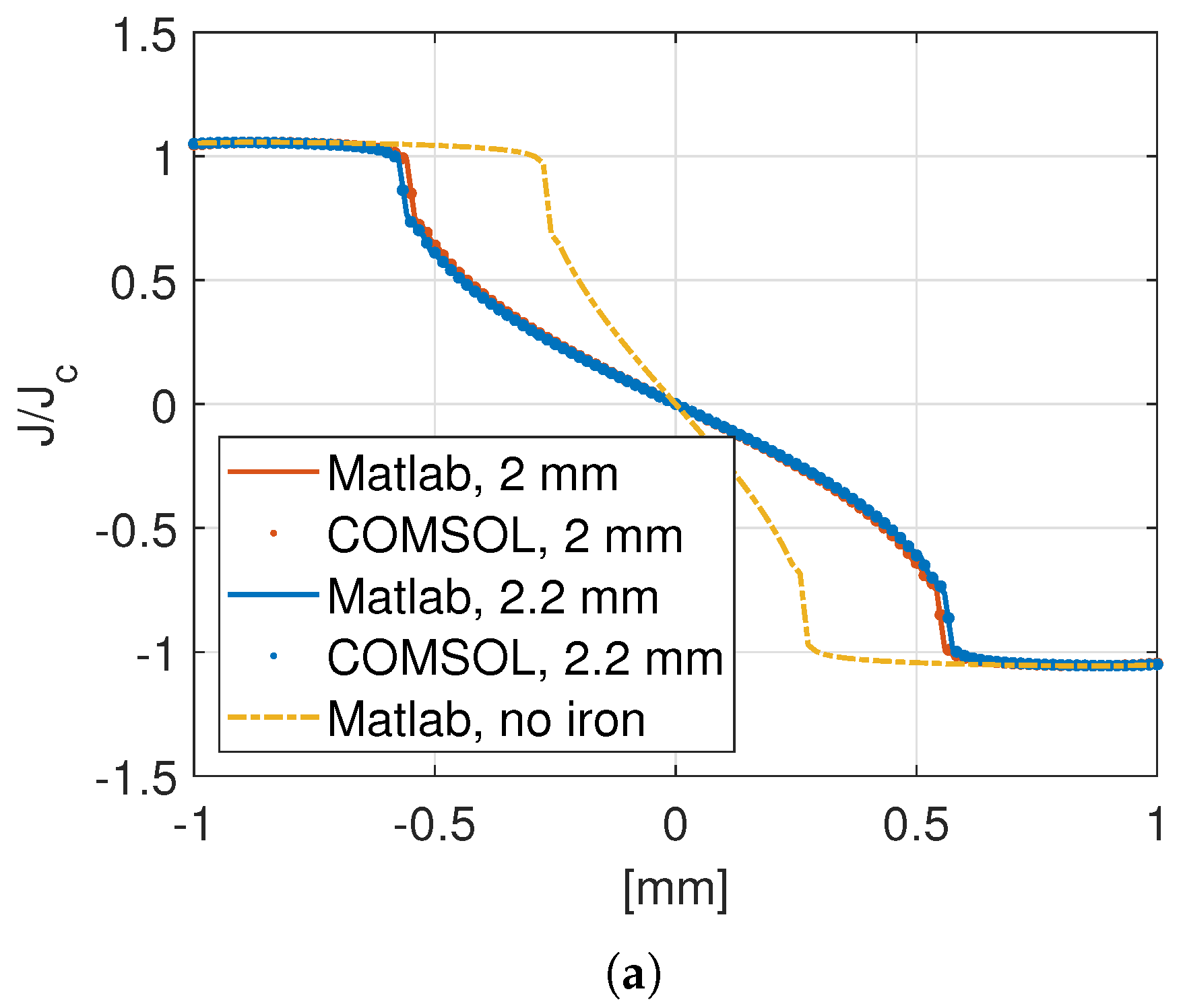
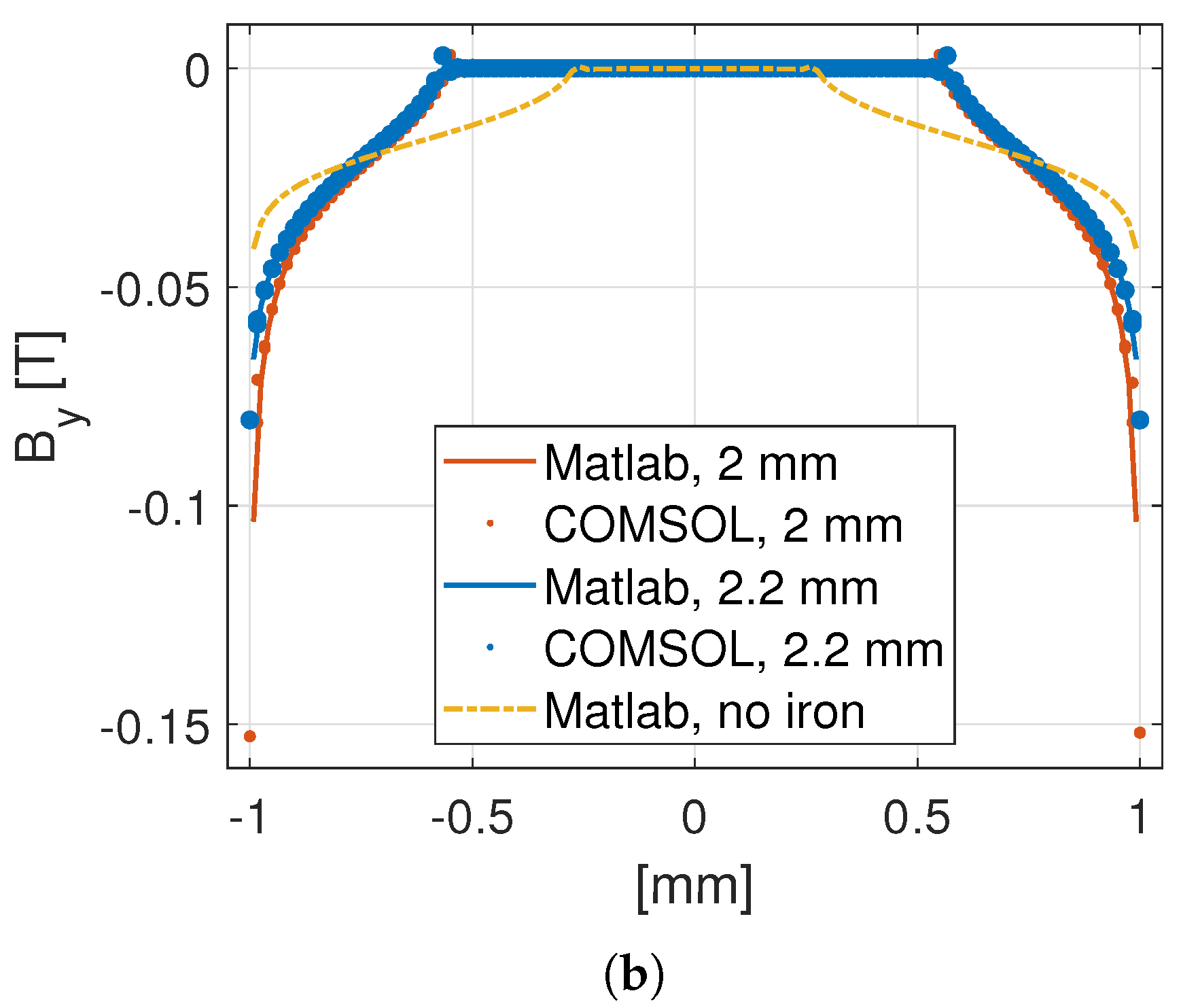
The instantaneous values of J / J c and B y across the width of the tapes with 2 mm and 2.2 mm substrate when the external magnetic field is B a , y = 20 mT during the sinusoidal cycle of amplitude B ext , 0 = 20 mT are shown in Figure 6a and Figure 6b, respectively. Good agreements can be seen between the values calculated in Matlab and COMSOL.

4.2. Tapes near Stator Iron

The second example considers HTS tapes in a stator slot of an electrical machine. The stator iron is the same as that in the SUTOR machine [51,52]. Two coil sides (labelled as coil sides 6 and 7, respectively) located in the same slot are modelled as two stacks of HTS tapes, and each stack has six tapes. The SUTOR machine in [51] has 52 tapes per coil side but, for verification of the modified Brandt method, here we model only 6 tapes. However, the 2390 ampere-turns of each coil side is the same between this paper and [51]. As noted in the introduction, the time taken by the modified Brandt method suffers more from the increase in the number of elements than FEM. Thus, homogenisation [35] can be considered when modelling a large number of tapes to reduce the number of elements. The transport current in each tape turn in the two coil sides are, respectively, as follows:
I s e t , 6 = I 0 cos 2 π f t 2 π 3 r ( 10 f t )
I s e t , 7 = I 0 cos ( 2 π f t ) r ( 10 f t )
r ( x ) = 1 + e 5 ( x 1.8 ) 1 ,
where I 0 = 398 A, f = 44 Hz, and r ( x ) is a ramp function to allow zero initial conditions.
The critical current of each tape is chosen as 500 A and is assumed to be constant (independent of magnetic field). The stator iron is modelled to have constant μ r = 5000 . Each tape is discretized into 100 elements linearly distributed along the width of the tape. In COMSOL simulations, the HTS tape turns are modelled as 1D lines via the T-A formulation.
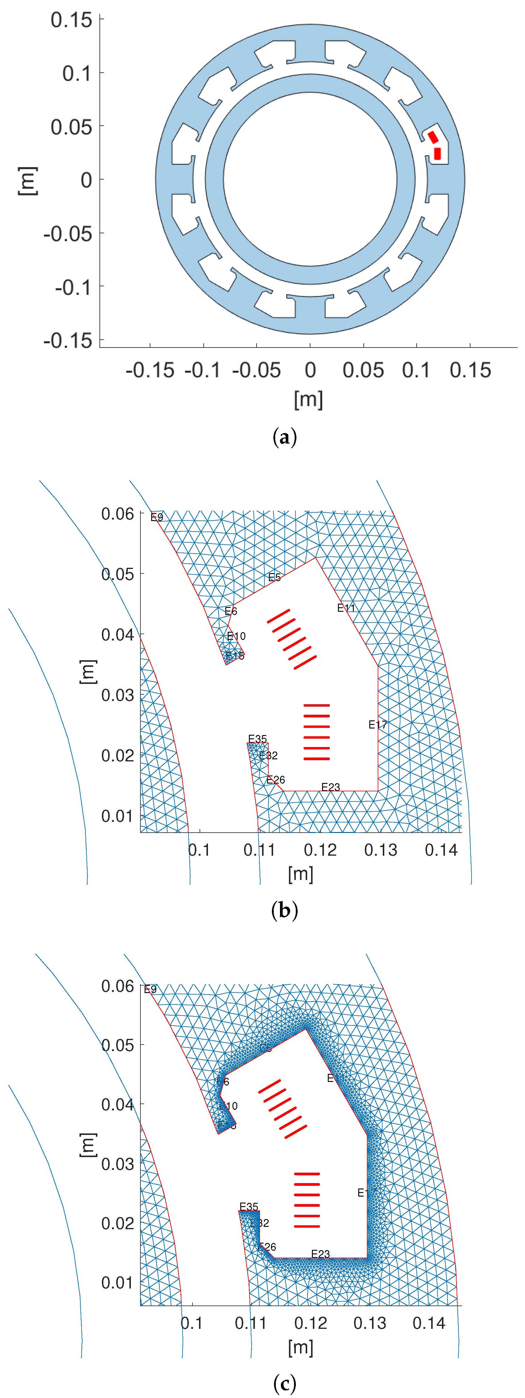
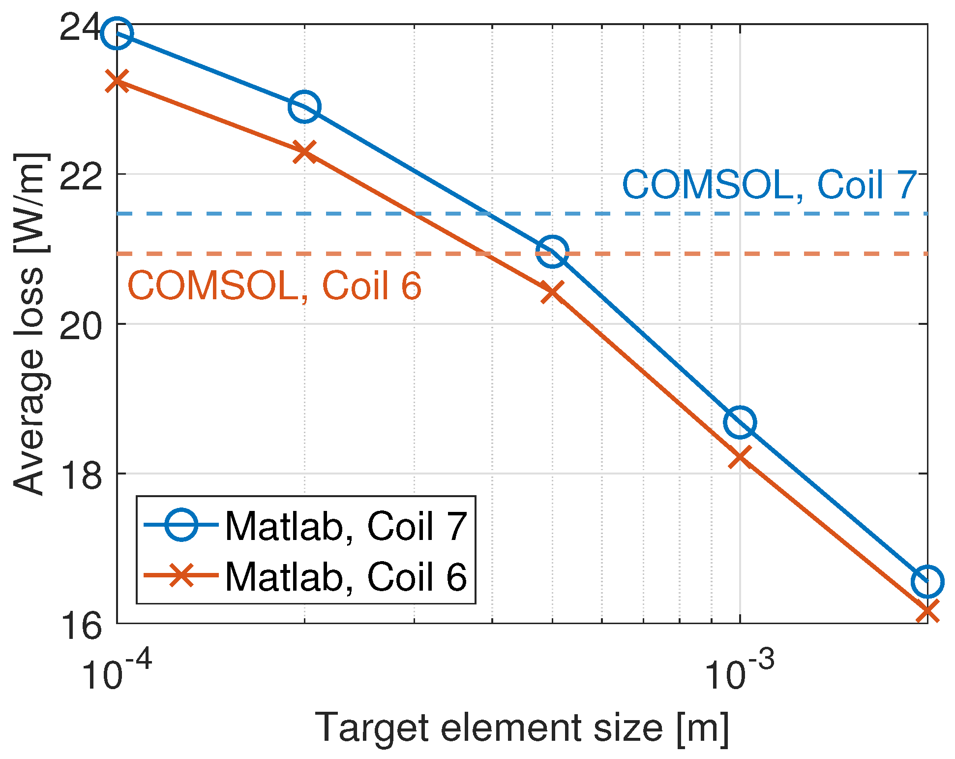
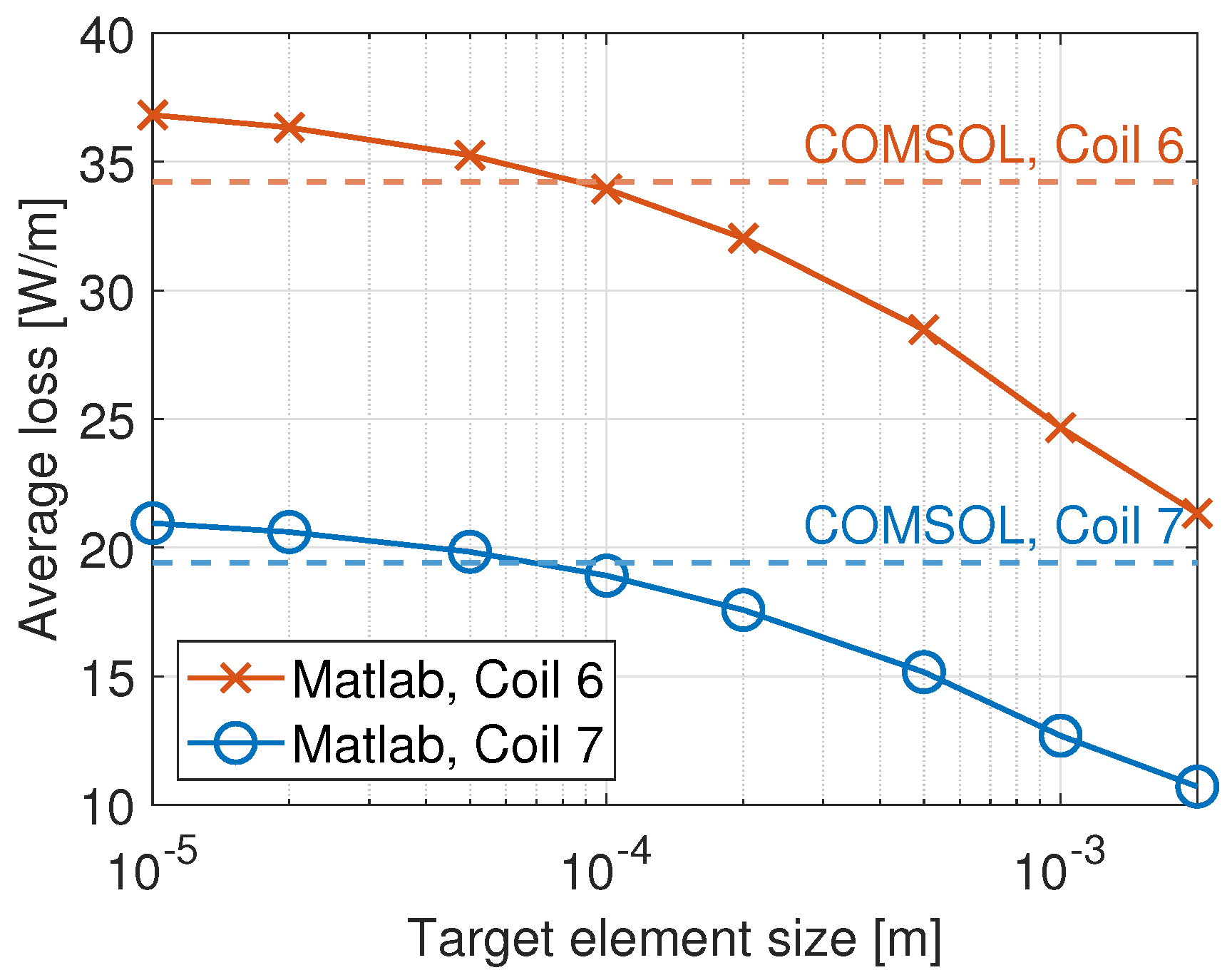
Figure 3a shows the geometry modelled in the modified Brandt method, except that the rotor iron is not modelled. Figure 3b,c show the adjustment of the size of the boundary elements. It is found that the ac loss calculated by the modified Brandt method depends heavily on the fineness of the discretization of the section of the iron boundary closest to the tapes. As the target size of the section of the iron boundary near the tapes is adjusted in Matlab, the average ac loss (averaged over the second half of first period simulated) is shown in Figure 7. It can be seen that, at coarse discretization, the modified Brandt method gives ac loss results that are below the COMSOL value; when the discretization is too fine, the ac loss result of the modified Brandt method overshoots the value of COMSOL. Thus, it seems that the modified Brandt method that considers iron as an equivalent surface current density suffers from the problem of the high sensitivity of the fineness of the discretization of the iron boundary. In contrast, COMSOL simulations are not affected by iron mesh density, as shown in Table 2. The average ac loss in the two coil sides remain similar despite a significant increase in mesh density.
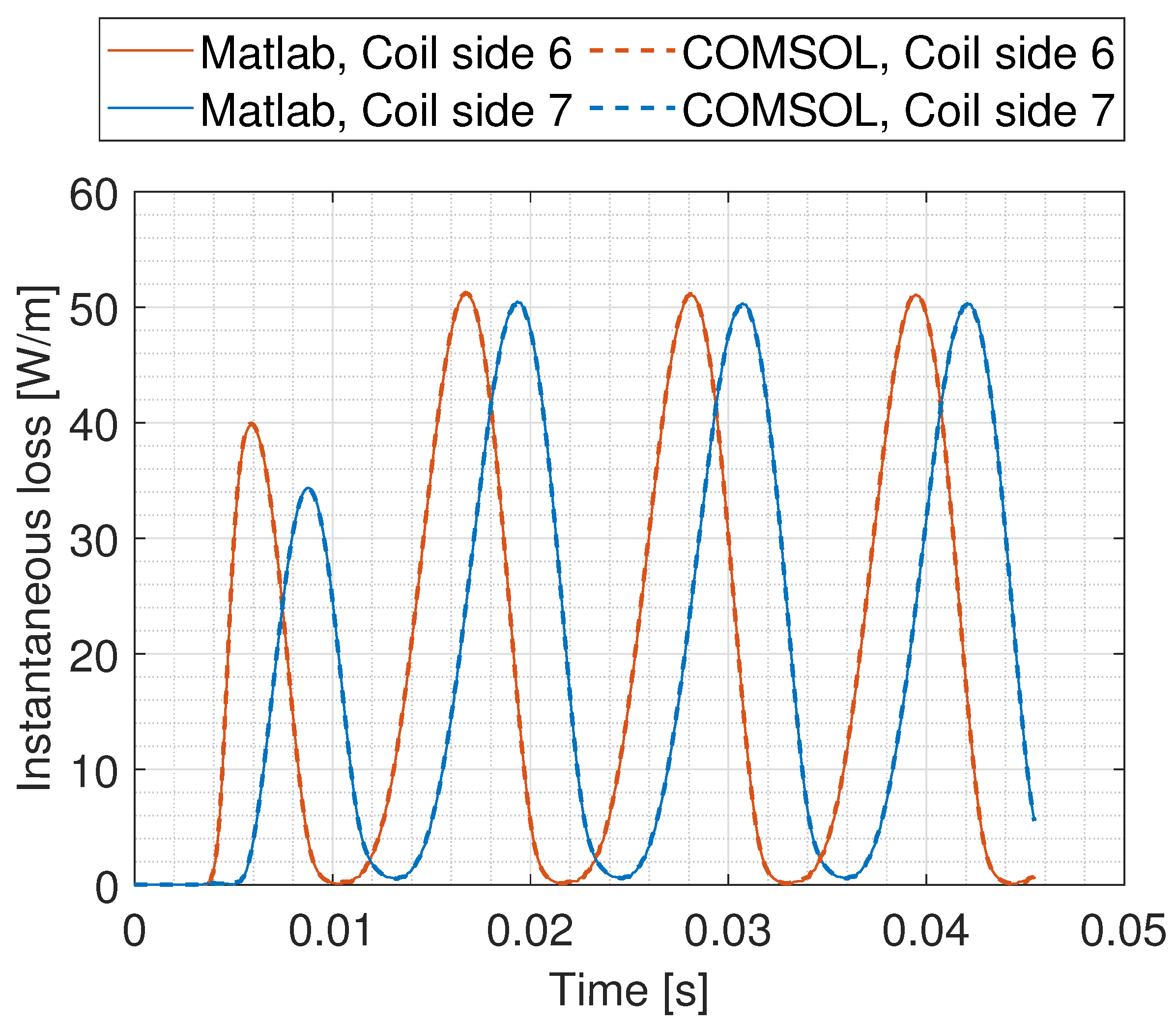
The instantaneous loss of the two coil sides calculated by the COMSOL model and the modified Brandt method model (with target element size 4 × 10 4 m) in Matlab are shown in Figure 8. For this particular mesh size, there is good agreement between the modified Brandt method in Matlab and the T-A formulation in COMSOL.

4.3. Machine Environment

4.3.1. COMSOL Reference Model

The third example extends the second example by trying to simulate the loss of the HTS tapes in a full machine environment. In the COMSOL model (the reference with which the modified Brandt method will be compared), the SUTOR machine [51,52] is simulated, except that, instead of simulating 52 tapes in each coil side, only 6 tapes are present in each coil side, but with increased transport current to keep the total ampere-turns per coil side the same. There are PMs on the rotating rotor. In the stator, there are iron and armature coils. For the armature coils, all but two coil sides are represented by areas through which spatially uniform current densities flow (the current densities differ between areas); two coil sides (labelled as coil sides 6 and 7, respectively) are modelled as two stacks of HTS tapes, as in Section 4.2. The HTS tapes are simulated via the T-A formulation.

4.3.2. Modified Brandt Method Model with Stator and Rotor Iron

The modified Brandt method’s geometry is the same as in Section 4.2 except that now there is rotor iron as well, as shown in Figure 3a. To take into account the magnetic field produced by the rotor PMs and other stator coil sides (both of which are not shown in Figure 3a) not modelled explicitly in the modified Brandt method, the HTS tapes are subject to an external magnetic field B a . The calculation of B a is explained as follows.
Since the iron is modelled to have a constant μ r , the principle of superposition applies and the magnetic field in the tapes’ area (which we call field (1)) is the sum of magnetic fields generated by other coil sides and PMs, which is then modified by presence of iron (which we call field (2)), and the magnetic field generated by current distribution in tapes, with the field modified by presence of iron (which we call field (3)). In other words, we expect the following:
( 1 ) = ( 2 ) + ( 3 ) .
Thus, B a is field (2) and is calculated in a COMSOL model that is the same as the full machine reference model but without the HTS tapes. The A ˙ at locations around the HTS tapes at different time points are exported and used for interpolation to find A a ˙ in (40) at the HTS tape elements’ positions at any given time in the modified Brandt method. Field (3) is different from that calculated in Section 4.2 because the presence of external field B a would affect the current distribution.
The average ac loss calculated by the modified Brandt method in Matlab with different mesh densities in the iron boundary near the tapes is shown in Figure 9. The loss calculated by the COMSOL reference model is also shown in the same figure. Again, the ac loss calculated by the modified Brandt method depends heavily on the mesh density.
The instantaneous loss of the two coil sides calculated by the COMSOL model and the modified Brandt method model (with target element size 8 × 10 5 m) in Matlab are shown in Figure 10. For this particular mesh size, there is good agreement between the modified Brandt method in Matlab and the T-A formulation in COMSOL.

4.3.3. Modified Brandt Method Model Without Iron

An alternative way to take into account iron is presented in this section. A modified Brandt method assumes that the tapes are in air (with no iron modelled in the geometry of this modified Brandt method), but an alternative background field A a is used, as follows. The magnetic field in the tapes’ area (which we call field (1)) in the full machine can be approximated as follows:
( 1 ) ( 1 u ) ( 4 ) + ( 5 ) ,
where ( 1 u ) is the field generated in a full machine but with uniform surface current density in the tapes, as calculated in COMSOL (tapes are modelled as surface current in the COMSOL model); ( 4 ) is the field generated by tapes in air with uniform surface current density, calculated in COMSOL; ( 5 ) is the field generated by tapes in air carrying the prescribed current under background field ( 1 u ) ( 4 ) , and the current distribution is not uniform but calculated by the modified Brandt method in Matlab. In other words, the effect of iron on the fields generated by the HTS tapes, the other coil sides, and PMs, are taken into account in ( 1 u ) , assuming uniform current distribution in tapes. However, ( 1 u ) alone cannot be the external field input into the modified Brandt method model (which models tapes in air only) because the tapes with current generate their own self-field. Thus, the external field in the modified Brandt method model must subtract the self-field ( 4 ) generated by the tapes. A similar method is proposed in reference [52], in which the Minimum Electro-Magnetic Entropy Production (MEMEP) method is used instead of the modified Brandt method, and that the background field is ( 1 u ) alone.
Therefore, now the modified Brandt method model in Matlab models tapes in air only, with external field ( 1 u ) ( 4 ) ( A a ˙ specifically is needed in the modified Brandt method) coming from two COMSOl models: ( 1 u ) is from a full machine model but with uniform surface current density in the tapes, and (4) is from a model with tapes in air carrying the same uniform surface current density.
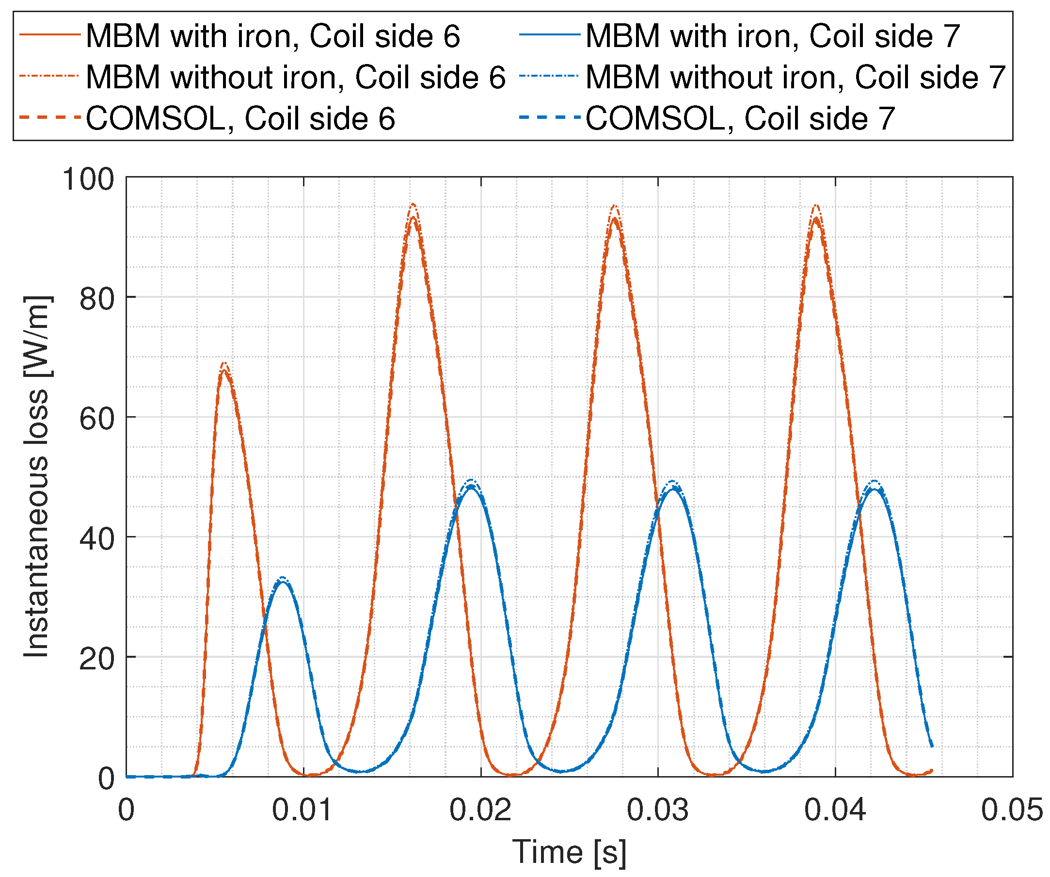
The instantaneous ac loss calculated by the COMSOL reference model (Section 4.3.1), the modified Brandt method model with iron (Section 4.3.2) with the target mesh density of the iron boundary surrounding the tapes being 0.08 mm, and the modified Brandt method model without iron (Section 4.3.3), are shown in Figure 10. The average ac loss in the second period simulated in Coil 6 calculated by the three models are 34.3643, 35.2744, and 34.2131 W/m, respectively; the losses in Coil 7 calculated by the three models are 19.2133, 19.8650, and 19.4099 W/m, respectively. Thus, the results suggest that the modified Brandt method model without iron (Section 4.3.3) can be a reasonably accurate alternative to the T-A formulation and the modified Brandt method model with iron (Section 4.3.2).

5. Conclusions

This paper has extended the modified Brandt method proposed by Statra et al. [45] (with iron being considered an equivalent surface current) to include the effect of an external magnetic field. When applied to the Benchmark #2 problem, the proposed modified Brandt method produces average ac loss results that agree closely (error less than 3%) with the widely-used T-A formulation implemented in COMSOL down to 2 mT.
There is mixed success when using the proposed modified Brandt method on HTS tapes (1) in a stator iron core and (2) in an iron-cored machine. On the one hand, at the appropriate fineness of the discretization of the iron boundary, the ac loss calculated by the modified Brandt method matches well with that calculated by the T-A formulation in COMSOL. On the other hand, when the discretization is too coarse (element size of iron boundary too big), the modified Brandt method gives ac loss results that are below the value calculated by COMSOL; when the discretization is too fine (element size of iron boundary too small), the ac loss result of the modified Brandt method overshoots the value calculated by COMSOL, thus one cannot assume using a fine discretization from the start will guarantee good results. The cause of the overshoot can be investigated in the future.

Author Contributions

Conceptualization, C.C.T.C.; methodology, C.C.T.C. and F.G.; software, C.C.T.C.; validation, C.C.T.C. and F.G.; resources, F.G. and K.T.C.; writing—original draft preparation, C.C.T.C.; writing—review and editing, F.G., K.T.C.; visualization, C.C.T.C.; supervision, F.G., K.T.C.; project administration, F.G.; funding acquisition, K.T.C. All authors have read and agreed to the published version of the manuscript.

Funding

This work was supported in part by the Hong Kong Research Grants Council under Project No. 17204021, and The Hong Kong Polytechnic University under Project Nos. P0048560 and P0046563, Hong Kong Special Administrative Region, China.

Institutional Review Board Statement

Not applicable.

Informed Consent Statement

Not applicable.

Data Availability Statement

The original contributions presented in this study are included in the article. Further inquiries can be directed to the corresponding authors.

Acknowledgments

The authors gratefully acknowledge discussion with Hocine Menana on the modified Brandt method for modelling HTS tapes near ferromagnetic material.

Conflicts of Interest

The authors declare no conflicts of interest.

Abbreviations

The following abbreviations are used in this manuscript:
FEMfinite element method
HTShigh-temperature superconducting
MECmagnetic equivalent circuit
PMpermanent magnet

Appendix A. Closed Forms for Line and Area Integrals in Matrices

The closed form for the line and area integrals in (21), (22), (31)–(36) are given as follows.
Consider Δ Γ j to be a straight line connecting points a = ( x 1 , y 1 ) and b = ( x 2 , y 2 ) . Let v be defined as follows:
v = v x v y : = b a | b a | .
Then, coordinates on Δ Γ j are described as r = a + p v where p [ 0 , P ] where P is the length of line Δ Γ j . Recall that the Green function (with minus sign) given by(9) is as follows:
Q = 1 2 π ln | r r | = 1 4 π ln ( x x ) 2 + ( y y ) 2 .

Appendix A.1. Line Integrals

The first line integral to be evaluated is as follows:
I 1 : = Δ Γ j Q ( r i , r ) d r = 0 P 1 4 π ln ( x i x 1 p v x ) 2 + ( y i y 1 p v y ) 2 d p = [ 1 4 π p ln c ( a p ) 2 + d ( b p ) 2 1 4 π a c + b d c + d ln c ( a p ) 2 + d ( b p ) 2 + 1 2 π c d ( a b ) c + d tan 1 ( c + d ) p ( a c + b d ) c d ( a b ) 1 4 π 2 p 2 a c + b d c + d ] p = 0 P ,
where a = x i x 1 v x ,   b = y i y 1 v y ,   c = v x 2 ,   d = v y 2 , for the general case v x 0 ,   v y 0 .
If v y = 0 , the line integral I 1 is as follows:
I 1 = 1 4 π 1 v x 2 u ( ln | u | 1 ) u = x i x 1 x i x 2 , y i = y 1 1 4 π 1 v x [ u ln ( u 2 + ( y i y 1 ) 2 ) 2 u   + 2 ( y i y 1 ) tan 1 u y i y 1 ] u = x i x 1 x i x 2 , y i y 1 .
If v x = 0 , the line integral I 1 is as follows:
I 1 = 1 4 π 1 v y 2 u ( ln | u | 1 ) u = y i y 1 y i y 2 , x i = x 1 1 4 π 1 v y [ u ln ( u 2 + ( x i x 1 ) 2 ) 2 u   + 2 ( x i x 1 ) tan 1 u y i y 1 ] u = y i y 1 y i y 2 , x i x 1 .
The second line integral to be evaluated is as follows:
I 3 : = Δ Γ j Q y ( r i , r ) d r = 1 4 π Δ Γ j 2 ( x i x ) ( x x ) 2 + ( y i y ) 2 d p = 1 4 π ( c + d ) [ c ln p 2 2 ( a c + b d ) c + d p + a 2 c + b 2 d c + d 2 d tan 1 ( c + d ) p ( a c + b d ) c d ( a b ) ] 0 P ,
for the general case v x 0 , v y 0 . Definitions of a , b , c , d are the same as for I 1 .
If v y = 0 , the line integral I 3 is as follows:
I 3 = 1 4 π 1 v x ln ( u 2 + ( y i y 1 ) 2 ) u = x i x 1 x i x 2 .
If v x = 0 , the line integral I 3 is as follows:
I 3 = 0 , x i = x 1 1 2 π 1 v y tan 1 u x i x 1 u = y i y 1 y i y 2 , x i x 1 .
Similarly, the third line integral to be evaluated is as follows:
I 4 : = Δ Γ j Q y ( r i , r ) d r = 1 4 π Δ Γ j 2 ( y i y ) ( x x ) 2 + ( y i y ) 2 d p = 1 4 π ( c + d ) [ c ln p 2 2 ( a c + b d ) c + d p + a 2 c + b 2 d c + d 2 d tan 1 ( c + d ) p ( a c + b d ) c d ( a b ) ] 0 P ,
where b = x i x 1 v x ,   a = y i y 1 v y ,   d = v x 2 ,   c = v y 2 , for the general case v x 0 , v y 0 .
If v x = 0 , the line integral I 4 is as follows:
I 4 = 1 4 π 1 v y ln ( u 2 + ( x i x 1 ) 2 ) u = y i y 1 y i y 2 .
If v y = 0 , the line integral I 4 is as follows:
I 4 = 0 , y i = y 1 1 2 π 1 v x tan 1 u y i y 1 u = x i x 1 x i x 2 , y i y 1 .

Appendix A.2. Area Integrals

For the next three area integrals over area Δ S j , Δ S j is considered a rectangle with sides parallel to the x or y axes covering a j < x < b j ,   c j < y < d j , with centre ( p j , q j ) , which is then rotated about the origin by angle θ to reach the final position with centre ( x j , y j ) . Let R = cos θ sin θ sin θ cos θ , then [ p j , q j ] T = R 1 [ x j , y j ] T , and the substitution [ p , q ] T = R 1 [ x , y ] T will be used below in evaluating the integrals. For the source point ( x i , y i ) , there is [ p i , q i ] T = R 1 [ x i , y i ] T .
The first area integral to be evaluated is as follows:
I 2 : = Δ S j Q ( r i , r ) d 2 r = Δ S j 1 4 π ln ( x i x ) 2 + ( y i y ) 2 d x d y = c j d j a j b j 1 4 π ln ( x i p cos θ + q sin θ ) 2 + ( y i p sin θ q cos θ ) 2 d p d q = c j d j a j b j 1 4 π ln ( p i p ) 2 + ( q i q ) 2 d p d q = 1 4 π u v ln ( u 2 + v 2 ) 3 + u 2 tan 1 v u + v 2 tan 1 u v u 1 u 2 v 1 v 2 ,
where u 1 = p i a j ,   u 2 = p i b j ,   v 1 = q i c j ,   v 2 = q i d j , where a j = p j d 2 2 ,   b j = p j + d 2 2 ,   c j = q j d 1 2 ,   d j = q j + d 1 2 , where d 1 = d j c j and d 2 = b j a j are the width and length of the rectangle Δ S j .
The second area integral to be evaluated is as follows:
I 5 : = Δ S j Q x ( r i , r ) d 2 r = 1 4 π Δ S j 2 ( x i x ) ( x x ) 2 + ( y i y ) 2 d x d y = 1 4 π c j d j a j b j 2 ( x i p cos θ + q sin θ ) ( p i p ) 2 + ( q i q ) 2 d p d q = cos θ 4 π I 51 + sin θ 4 π I 52 ,
where I 51 and I 52 are as follows:
I 51 = v 1 v 2 u 1 u 2 2 u u 2 + v 2 d u d v = v ln ( u 2 + v 2 ) + 2 u tan 1 v u u 1 u 2 v 1 v 2
I 52 = v 1 v 2 u 1 u 2 2 v u 2 + v 2 d u d v = u ln ( u 2 + v 2 ) + 2 v tan 1 u v u 1 u 2 v 1 v 2 ,
where u 1 ,   u 2 ,   v 1 ,   v 2 ,   a j ,   b j ,   c j ,   d j ,   d 1 ,   d 2 have the same meaning as for I 4 .
Similarly, the third area integral to be evaluated is as follows:
I 6 : = Δ S j Q y ( r i , r ) d 2 r = sin θ 4 π I 51 cos θ 4 π I 52 .

References

  1. Coombs, T.A.; Wang, Q.; Shah, A.; Hu, J.; Hao, L.; Patel, I.; Wei, H.; Wu, Y.; Coombs, T.; Wang, W. High-temperature superconductors and their large-scale applications. Nat. Rev. Electr. Eng. 2024, 1, 788–801. [Google Scholar] [CrossRef]
  2. Paidpilli, M.; Selvamanickam, V. Development of RE-Ba-Cu-O superconductors in the U.S. for ultra-high field magnets. Supercond. Sci. Technol. 2022, 35, 043001. [Google Scholar] [CrossRef]
  3. Yanagisawa, Y.; Hamada, M.; Hashi, K.; Maeda, H. Review of recent developments in ultra-high field (UHF) NMR magnets in the Asia region. Supercond. Sci. Technol. 2022, 35, 044006. [Google Scholar] [CrossRef]
  4. Chow, C.C.T.; Ainslie, M.D.; Chau, K.T. High temperature superconducting rotating electrical machines: An overview. Energy Rep. 2023, 9, 1124–1156. [Google Scholar] [CrossRef]
  5. Mitchell, N.; Zheng, J.; Vorpahl, C.; Corato, V.; Sanabria, C.; Segal, M.; Sorbom, B.; Slade, R.; Brittles, G.; Bateman, R.; et al. Superconductors for fusion: A roadmap. Supercond. Sci. Technol. 2021, 34, 103001. [Google Scholar] [CrossRef]
  6. Ferracin, P.; Ambrosio, G.; Arbelaez, D.; Brouwer, L.; Barzi, E.; Cooley, L.; Garcia Fajardo, L.; Gupta, R.; Juchno, M.; Kashikhin, V.; et al. Towards 20 T hybrid accelerator dipole magnets. IEEE Trans. Appl. Supercond. 2022, 32, 4000906. [Google Scholar] [CrossRef]
  7. Zhang, G.; Wang, H.; Qiu, Q.; Zhang, Z.; Xiao, L.; Lin, L. Recent progress of superconducting fault current limiter in China. Supercond. Sci. Technol. 2020, 34, 013001. [Google Scholar] [CrossRef]
  8. Yazdani-Asrami, M.; Seyyedbarzegar, S.; Sadeghi, A.; de Sousa, W.T.B.; Kottonau, D. High temperature superconducting cables and their performance against short circuit faults: Current development, challenges, solutions, and future trends. Supercond. Sci. Technol. 2022, 35, 083002. [Google Scholar] [CrossRef]
  9. Diyun, W.; Chau, K.T.; Chunhua, L.; Shuang, G.; Fuhua, L. Transient stability analysis of SMES for smart grid with vehicle-to-grid operation. IEEE Trans. Appl. Supercond. 2012, 22, 5701105. [Google Scholar] [CrossRef]
  10. Kajikawa, K.; Hayashi, T.; Yoshida, R.; Iwakuma, M.; Funaki, K. Numerical evaluation of ac losses in HTS wires with 2D FEM formulated by self magnetic field. IEEE Trans. Appl. Supercond. 2003, 13, 3630–3633. [Google Scholar] [CrossRef]
  11. Pecher, R.; McCulloch, M.; Chapman, S.J.; Prigozhin, L.; Elliott, C.M. 3D-modelling of bulk type-II superconductors using unconstrained H-formulation. Inst. Phys. Conf. Ser. 2003, 181, 1418. [Google Scholar]
  12. Shen, B.; Grilli, F.; Coombs, T. Review of the ac loss computation for HTS using H formulation. Supercond. Sci. Technol. 2020, 33, 033002. [Google Scholar] [CrossRef]
  13. Liang, F.; Venuturumilli, S.; Zhang, H.; Zhang, M.; Kvitkovic, J.; Pamidi, S.; Wang, Y.; Yuan, W. A finite element model for simulating second generation high temperature superconducting coils/stacks with large number of turns. J. Appl. Phys. 2017, 122, 043903. [Google Scholar] [CrossRef]
  14. Zhang, H.; Zhang, M.; Yuan, W. An efficient 3D finite element method model based on the T–A formulation for superconducting coated conductors. Supercond. Sci. Technol. 2017, 30, 024005. [Google Scholar] [CrossRef]
  15. Huber, F.; Song, W.; Zhang, M.; Grilli, F. The T-A formulation: An efficient approach to model the macroscopic electromagnetic behaviour of HTS coated conductor applications. Supercond. Sci. Technol. 2022, 35, 043003. [Google Scholar] [CrossRef]
  16. Brandt, E.H. Superconductors of finite thickness in a perpendicular magnetic field: Strips and slabs. Phys. Rev. B 1996, 54, 4246–4264. [Google Scholar] [CrossRef]
  17. Rhyner, J. Calculation of AC losses in HTSC wires with arbitrary current voltage characteristics. Phys. C 1998, 310, 42–47. [Google Scholar] [CrossRef]
  18. Yang, Y.; Martinez, E.; Beduz, C. Numerical modeling of the critical state and calculation of ac losses and current profiles in multi-filamentary Bi-2223 tapes. Inst. Phys. Conf. Ser. 1999, 167, 855–858. [Google Scholar]
  19. Klinčok, B.; Gömöry, F.; Pardo, E. The voltage signal on a superconducting wire in ac transport. Supercond. Sci. Technol. 2005, 18, 694–700. [Google Scholar] [CrossRef]
  20. Vojenčiak, M.; Šouc, J.; Ceballos, J.M.; Klinčok, B.; Gömöry, F.; Pardo, E.; Grilli, F. Losses in Bi-2223/Ag tape at simultaneous action of ac transport and ac magnetic field shifted in phase. J. Phys. Conf. Ser. 2006, 43, 63–66. [Google Scholar] [CrossRef]
  21. Klinčok, B.; Gömöry, F. Influence of gaps in monolayer superconducting cable on ac losses. J. Phys. Conf. Ser. 2006, 43, 897–900. [Google Scholar] [CrossRef]
  22. Yazawa, T.; Rabbers, J.J.; ten Haken, B.; ten Kate, H.H.J.; Maeda, H. AC loss analysis on high-temperature superconductors with finite thickness and arbitrary magnetic field dependent voltage–current relation. J. Appl. Phys. 1998, 84, 5652–5656. [Google Scholar] [CrossRef]
  23. Nguyen, D.N.; Sastry, P.V.P.S.S.; Knoll, D.C.; Zhang, G.; Schwartz, J. Experimental and numerical studies of the effect of phase difference between transport current and perpendicular applied magnetic field on total ac loss in Ag-sheathed (Bi,Pb)2Sr2Ca2Cu3Ox tape. J. Appl. Phys. 2005, 98, 073902. [Google Scholar] [CrossRef]
  24. Nguyen, D.N.; Sastry, P.V.P.S.S.; Schwartz, J. Numerical calculations of the total ac loss of Cu-stabilized YBa2Cu3O7-δ coated conductor with a ferromagnetic substrate. J. Appl. Phys. 2007, 101, 053905. [Google Scholar] [CrossRef]
  25. Zhong, J.; Zou, S.; Lai, L.; Chen, P.; Deng, S. Fast evaluation of the critical current of high-temperature superconducting coils based on the integral method. J. Appl. Phys. 2022, 132, 163901. [Google Scholar] [CrossRef]
  26. Lucchini, F.; Torchio, R.; Morandi, A.; Dughiero, F. A Fast Integral Equation J-φ Formulation for Superconducting Structures. IEEE Trans. Appl. Supercond. 2024, 34, 5901808. [Google Scholar] [CrossRef]
  27. Zhang, H.; Kang, X.; Song, P.; Guan, M.; Qu, T.; Wang, X. An advanced computational approach for evaluating screening-current-induced strain in REBCO HTS coils considering electromagnetic-mechanical coupling. IEEE Trans. Appl. Supercond. 2024, 34, 4601105. [Google Scholar] [CrossRef]
  28. Kang, X.; Zhang, H.; Tong, Y.; Wang, X. Bidirectionally coupled electromagnetic modeling of inductive behavior and screening currents in HTS no-insulation coils. Supercond. Sci. Technol. 2025, 38, 075019. [Google Scholar] [CrossRef]
  29. Elbaa, M.; Berger, K.; Douine, B.; Halit, M.; Ailam, E.H.; Bentridi, S.E. Analytical modeling of an inductor in a magnetic circuit for pulsed field magnetization of HTS bulks. IEEE Trans. Appl. Supercond. 2018, 28, 8201306. [Google Scholar] [CrossRef]
  30. Otten, S.; Grilli, F. Simple and fast method for computing induced currents in superconductors using freely available solvers for ordinary differential equations. IEEE Trans. Appl. Supercond. 2019, 29, 8202008. [Google Scholar] [CrossRef]
  31. Otten, S.; Kario, A.; Demenčik, E.; Nast, R.; Grilli, F. Anisotropic monoblock model for computing ac loss in partially coupled Roebel cables. Supercond. Sci. Technol. 2020, 33, 094013. [Google Scholar] [CrossRef]
  32. Musso, A.; Breschi, M.; Ribani, P.L.; Grilli, F. Analysis of ac loss contributions from different layers of HTS tapes using the A–V formulation model. IEEE Trans. Appl. Supercond. 2021, 31, 5900411. [Google Scholar] [CrossRef]
  33. Lai, L.; Gu, C. AC loss calculation in REBCO coils or stacks by solving the equation of motion for current using an integration approach. Supercond. Sci. Technol. 2021, 34, 015003. [Google Scholar] [CrossRef]
  34. Lai, L.; Gu, C. J model for studying ac magnetization loss in 3D cable structures. Supercond. Sci. Technol. 2022, 35, 045008. [Google Scholar] [CrossRef]
  35. Kang, X.; Wang, X. A homogenised anisotropic J-model for accelerating computations of screening current profile in large-scale HTS magnets. Supercond. Sci. Technol. 2023, 36, 035011. [Google Scholar] [CrossRef]
  36. Chow, C.C.T.; Grilli, F.; Chau, K.T. Numerical modelling of HTS tapes under arbitrary external field and transport current via integral method: Review and application to electrical machines. Supercond. Sci. Technol. 2023, 36, 115027. [Google Scholar] [CrossRef]
  37. Chow, C.C.T.; Zhang, M.; Chau, K.T.; Grilli, F. Modeling HTS coils with different coupling scenarios via integral method. IEEE Trans. Appl. Supercond. 2024, 34, 4606809. [Google Scholar] [CrossRef]
  38. Gottardi, E.; Krop, D.C.J.; Lomonova, E.A. A hybrid model for studying ac losses in HTS tapes of a linear machine. J. Phys. Conf. Ser. 2025, 3054, 012011. [Google Scholar] [CrossRef]
  39. Kalsi, S. Influence of magnetic iron teeth in motors employing superconductors for field excitation and ac stator windings. IEEE Trans. Appl. Supercond. 2021, 31, 5201607. [Google Scholar] [CrossRef]
  40. Patel, A.; Climente-Alarcon, V.; Baskys, A.; Glowacki, B.A.; Reis, T. Design considerations for fully superconducting synchronous motors aimed at future electric aircraft. In Proceedings of the 2018 IEEE International Conference on Electrical Systems for Aircraft, Railway, Ship Propulsion and Road Vehicles & International Transportation Electrification Conference (ESARS-ITEC), Nottingham, UK, 7–9 November 2018. [Google Scholar] [CrossRef]
  41. Lee, C.H.T.; Chau, K.T.; Liu, C.; Ching, T.W.; Chen, M. A new magnetless flux-reversal HTS machine for direct-drive application. IEEE Trans. Appl. Supercond. 2015, 25, 5203105. [Google Scholar] [CrossRef]
  42. Wang, Y.; Sun, J.; Zou, Z.; Wang, Z.; Chau, K.T. Design and analysis of a HTS flux-switching machine for wind energy conversion. IEEE Trans. Appl. Supercond. 2013, 23, 5000904. [Google Scholar] [CrossRef]
  43. Jian, L.; Chau, K.T.; Li, W.; Li, J. A novel coaxial magnetic gear using bulk HTS for industrial applications. IEEE Trans. Appl. Supercond. 2010, 20, 981–984. [Google Scholar] [CrossRef]
  44. Zhu, H.; Ma, J.; Feng, B.; Zhang, Z.; Mellor, P. J-Φ coupled model based on integral methods and magnetic networks for superconductor. Supercond. Sci. Technol. 2025, 38, 055017. [Google Scholar] [CrossRef]
  45. Statra, Y.; Menana, H.; Douine, B. Semianalytical modeling of ac Losses in HTS stacks near ferromagnetic parts. IEEE Trans. Appl. Supercond. 2021, 31, 5900306. [Google Scholar] [CrossRef]
  46. Statra, Y.; Menana, H.; Douine, B. Integral modeling of ac losses in HTS tapes with magnetic substrates. IEEE Trans. Appl. Supercond. 2022, 32, 5900407. [Google Scholar] [CrossRef]
  47. Benchmark #2. Available online: https://htsmodelling.com/benchmark-2 (accessed on 22 August 2025).
  48. Sirois, F.; Roy, F. Computation of 2-D current distribution in superconductors of arbitrary shapes using a new semi-analytical method. IEEE Trans. Appl. Supercond. 2007, 17, 3836–3845. [Google Scholar] [CrossRef]
  49. Sirois, F.; Roy, F.; Dutoit, B. Assessment of the computational performances of the semi-analytical method (SAM) for computing 2-D current distributions in superconductors. IEEE Trans. Appl. Supercond. 2009, 19, 3600–3604. [Google Scholar] [CrossRef]
  50. Sadiku, M.N.O. Elements of Electromagnetics, 6th ed.; Oxford University Press: Oxford, UK, 2015; pp. 358–359. [Google Scholar]
  51. Benkel, T.; Lao, M.; Liu, Y.; Pardo, E.; Wolfstadter, S.; Reis, T.; Grilli, F. T-A-formulation to model electrical machines with HTS coated conductor coils. IEEE Trans. Appl. Supercond. 2020, 30, 5205807. [Google Scholar] [CrossRef]
  52. Pardo, E.; Grilli, F.; Liu, Y.; Wolftadler, S.; Reis, T. AC loss modeling in superconducting coils and motors with parallel tapes as conductor. IEEE Trans. Appl. Supercond. 2019, 29, 5202505. [Google Scholar] [CrossRef]
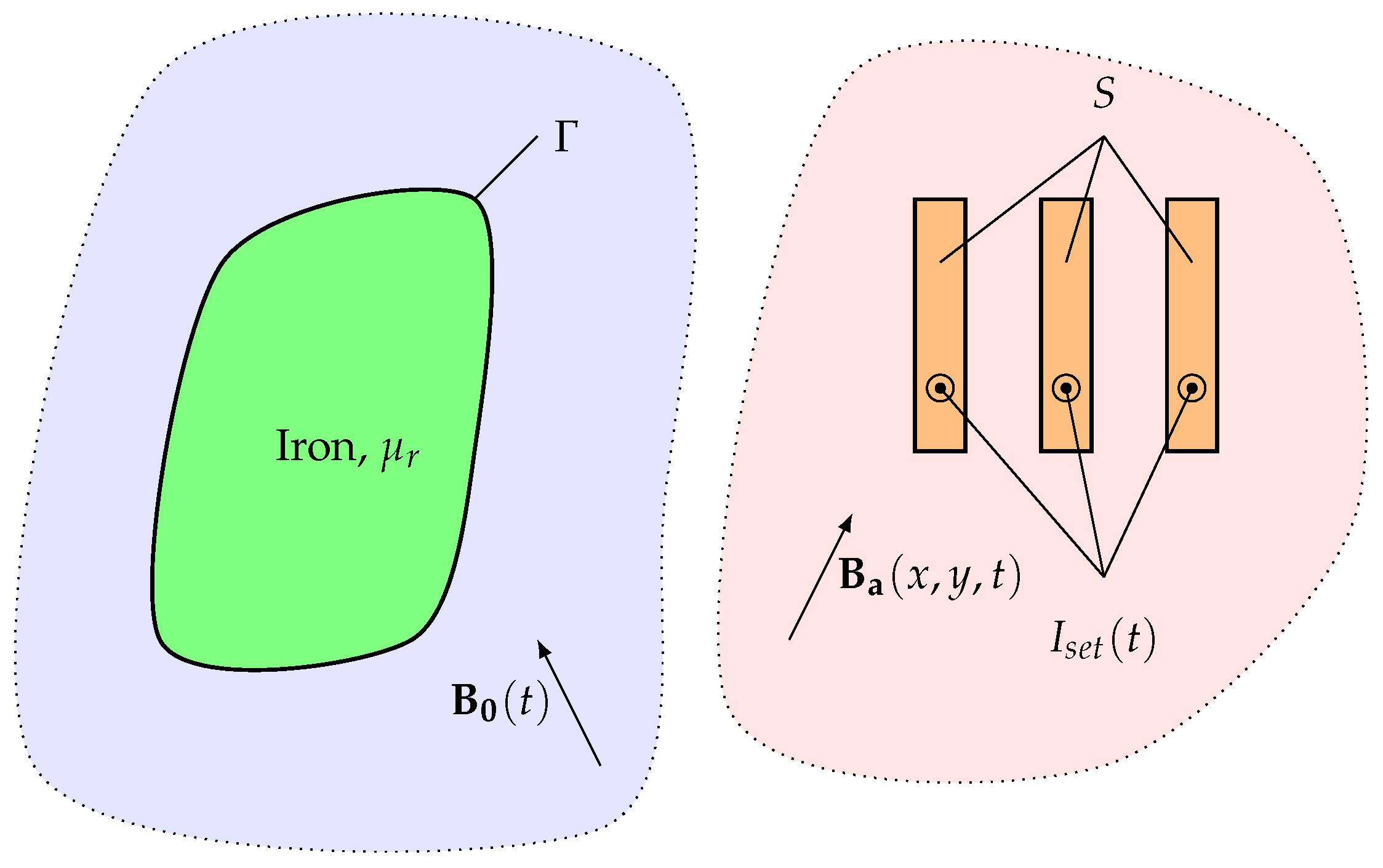
Figure 1. Model setup. Under some circumstances, B a and B 0 are the same, but there are situations where they are different.
Applsci 15 10411 g001
Figure 2. Benchmark #2’s geometry.
Applsci 15 10411 g002
Figure 3. (a) The geometry modelled in the modified Brandt method in Matlab. HTS tapes are shown in red in (a). In Section 4.2, there is no rotor iron. The size of elements Δ Γ i on the edges near the tapes when the target element size is (b) 0.002 m and (c) 0.0002 m. Whilst the face of the iron is also meshed in Matlab, only the elements on the edges are used in the modified Brandt method. The edges whose elements’ target size is adjusted are edges E15, E10, E6, E5, E11, E17, E23, E26, E32, E35. These edges are considered to be the edges of the iron boundary closest to the tapes.
Applsci 15 10411 g003
Figure 4. Each HTS layer is discretized into a single layer of 2D elements (two layers shown in figure). The red box shows the area Δ S j of element j, and the area of element j is integrated over in, e.g., (25), to calculate properties of element i with centre ( x i , y i ) . Figure reproduced from [36] under CC-BY 4.0.
Applsci 15 10411 g004
Figure 5. Average loss due to external magnetic field of different amplitudes as calculated by the modified Brandt method in Matlab and T-A formulation in COMSOL for HTS tape with magnetic substrates with widths of (a) 2 mm and (b) 2.2 mm. The circular dark orange points represent the percentage difference of loss calculated by Matlab compared to COMSOL, and the corresponding axis is the right axis on each graph.
Applsci 15 10411 g005
Figure 6. The instantaneous values of (a) J / J c and (b) B y across the width of the tape when the external magnetic field is B a , y = 20 mT during the sinusoidal cycle of amplitude 20 mT. The results are shown for calculations performed via the modified Brandt method in Matlab and T-A formulation in COMSOL, for both the geometries with 2 mm and 2.2 mm ferromagnetic substrates. For reference, the results for the case when there is no iron substrate are also shown.
Applsci 15 10411 g006aApplsci 15 10411 g006b
Figure 7. Average ac loss (averaged over the second half of the cycle simulated) for tapes near a stator iron calculated in Matlab when different target element sizes are used for the edges of the iron boundary closest to the tapes. The average ac loss calculated by COMSOL are also shown as horizontal lines.
Applsci 15 10411 g007
Figure 8. Instantaneous loss of the two coil sides carrying transport ac in a stator slot calculated in COMSOL and the modified Brandt method in Matlab.
Applsci 15 10411 g008
Figure 9. Average ac loss (averaged over the second half of the cycle simulated) for tapes in a machine environment calculated in Matlab when different target element sizes are used for the edges of the iron boundary closest to the tapes. The average ac loss calculated by COMSOL are also shown as horizontal lines.
Applsci 15 10411 g009
Figure 10. Instantaneous loss of the two coil sides in a machine environment calculated by the COMSOL reference model (Section 4.3.1), the modified Brandt method (MBM) model with iron (Section 4.3.2) with the target mesh density of the iron boundary surrounding the tapes being 0.08 mm, and the modified Brandt method model without iron (Section 4.3.3).
Applsci 15 10411 g010
Table 1. Average ac loss [W/m] in tape in Benchmark #2 calculated by the modified Brandt method for different substrate mesh densities and external magnetic field amplitudes.
2 mm Substrate2.2 mm Substrate
Target Element Size [m]0.002 T0.02 T0.2 T2 T0.002 T0.02 T0.2 T2 T
2.00 × 10 4 n/a0.0216731.105713.3625n/a0.0184291.091713.2740
1.00 × 10 4 n/a0.0216851.103913.3579n/a0.0182871.090513.2693
5.00 × 10 5 n/a0.0218421.101713.3298n/a0.0190041.089813.2478
2.00 × 10 5 2.96 × 10 5 0.0215801.097613.28831.50 × 10 5 0.0188641.086613.2149
1.00 × 10 5 3.07 × 10 5 0.0215391.096713.27847.14 × 10 6 0.0185981.085413.2064
5.00 × 10 6 3.10 × 10 5 0.0215151.096213.27378.35 × 10 6 0.0186451.085113.2026
2.00 × 10 6 3.13 × 10 5 0.0215111.096113.27207.89 × 10 6 0.0186211.085013.2011
1.00 × 10 6 3.14 × 10 5 0.0215071.096013.27147.88 × 10 6 0.0186181.084913.2006
5.00 × 10 7 1.32 × 10 6 n/an/an/a4.66 × 10 6 n/an/an/a
2.00 × 10 7 9.13 × 10 7 n/an/an/a1.25 × 10 6 n/an/an/a
1.00 × 10 7 8.27 × 10 7 n/an/an/a1.04 × 10 6 n/an/an/a
Table 2. Effect of iron mesh density on COMSOL simulations.
NormalDense
Max element size on edges 1 [mm]0.60.3
Number of edge elements on edges close to tapes 1164328
Number of triangles in stator iron15,77826,057
Average loss 2 coil side 6 [W/m]20.91420.918
Average loss 2 coil side 7 [W/m]21.45221.456
1 E15, E10, E6, E5, E11, E17, E23, E26, E32, E35 shown in Figure 3a. 2 Averaged over the second period simulated.
Disclaimer/Publisher’s Note: The statements, opinions and data contained in all publications are solely those of the individual author(s) and contributor(s) and not of MDPI and/or the editor(s). MDPI and/or the editor(s) disclaim responsibility for any injury to people or property resulting from any ideas, methods, instructions or products referred to in the content.