Abstract
Scaffolds are temporary structures that workers usually use during building or repair work. These structures can be built in different shapes and types depending on the type of joints to which the beams and columns of the scaffolds are connected. Due to their temporary nature, they are very sensitive to vibration under dynamic or static actions, and this causes many accidents and unstable behaviours in them. This unstable behaviour has different reasons, including bracing conditions and slenderness of the columns, stiffness of joints and anchors, imperfections in the construction, damage and corrosion due to climate change, etc. This article aims to reanalyse the mechanical properties of scaffold joints and anchors and obtain some critical factors in the overall stability of the mentioned structures, including load-bearing capacity, initial stiffness, energy absorption, and ductility. To this aim, some recent research on scaffolds has been summarised and discussed, and then the failure mode and mechanical behaviour of the scaffolds in different types of scaffold joints and anchors have been estimated and considered from previous studies. Moreover, some mechanical properties, including ductility, initial stiffness, and energy absorption, have been estimated and developed based on the force-displacement curves of previous studies. The results highlight the crucial importance of the mechanical properties and behaviour of anchors and joints in estimating the behaviour and stability of scaffolds. The results also revealed that determining the mechanical characteristics of the mentioned elements can have a significant influence on the optimisation and design of scaffolds more accurately and predictably. Moreover, determining the mechanical properties of the anchors and joints can enhance our insights and understanding of how the mentioned parameters can improve the behaviour, stability, and safety of the scaffold structures.
1. Introduction and Problem Statement
Scaffolds are temporary structures that are installed during building construction, and workers use them to repair or build parts of the building. These structures play a crucial role in making it easy and possible for workers to have access to the heights of buildings. This matter is made possible by the work platforms, vertical and horizontal elements, and anchors that connect the scaffolds to the buildings.
As they are temporary and workers work at heights, the safety of the people around them and the workers is important and significant [1]. Moreover, the stability of these structures can significantly affect the quality of the work that is being done on them. Especially in the case of reinforcing or repairing the crucial structural elements of the building. In other words, the use of scaffold structures is not limited to the repair or maintenance of the non-structural elements of buildings and minor maintenance, including painting or the façade of the building. Such structures can also be used in repairing or reinforcing the steel beams, concrete elements, etc. In such situations, the quality and stability of the scaffold structures can significantly and directly affect the quality of the structural elements of the buildings.
These structures are made of different joints, connections, materials, and geometric properties, which result in different types of scaffolds [2]. However, joints and anchors are one of the most important parts of these structures, and any imperfections or improper design or execution make the entire scaffold structure unstable and dangerous [1]. On the other hand, these parts of scaffolds are very weak because the connections are built temporarily, and this can make them loose [3,4]. One of the most important reasons for their weakness is poor design and execution supervision [5]. Therefore, these structures are sensitive to vibration because the stiffness of the properties of the material and the joints is uncertain [6,7]. Therefore, obtaining the mechanical properties of anchors and joints can have a significant influence on designing and predicting the behaviour of the scaffolds accurately.
There are some regulations regarding the design and execution of scaffoldings in Eurocode [8]. Although there are some regulations in Eurocode to protect the workers and people around them during work on the mentioned structures [3], these structures have some weaknesses, including high vibration under low displacement [6], and many accidents have occurred while using them [9]. This can be a result of temporary connections and joints. Another reason is related to the geometric properties of the scaffolds, which involve a long ratio of span over cross-section dimensions and large distances between vertical elements. The mentioned reasons cause unstable behaviour in the scaffolds.
Although various European Standards such as EN 12811-1 [8], EN 12810-1 [10], and other parts of the Eurocode provide general design and performance requirements for scaffolding systems, falsework, couplers, and temporary structures, they do not offer detailed mechanical parameters for joints and anchors. These codes focus primarily on safety, geometry, corrosion protection, and load classification, but they do not specify numerical values for stiffness, energy absorption, ductility, or comparative performance under different loading conditions [11].
For instance, EN 12811-1 outlines performance requirements for temporary works equipment but lacks specific criteria for energy dissipation or mechanical deformation characteristics of joints under cyclic or dynamic loading. Similarly, EN 74-1 [12] and EN 74-2 [13], which address coupler and baseplate characteristics, mention general mechanical behaviour but do not quantify parameters such as initial stiffness or failure energy [11].
Given this regulatory gap, scaffold designers and engineers are left without precise input values for simulation and risk assessment. Therefore, a comparative analytical review of existing empirical data on scaffold joints and anchors—as performed in this study—is both timely and necessary. By extracting and re-analysing force-displacement curves from experimental studies, this research provides quantitative insight into mechanical properties such as energy absorption, load-bearing capacity, and stiffness.
These findings contribute not only to design optimisation and performance prediction but also to code development efforts by suggesting benchmarks for evaluating scaffold joint performance, thus filling an important gap in current engineering standards.
2. Literature Review and State-of-the-Art
To solve the mentioned problems of the scaffold systems and improve their stability, a lot of research has been done on different types of scaffolds. In a recent paper, Ramezantitkanloo et al. [11] reviewed different types of anchors and joints, scaffold stability, safety protection, imperfections and inaccuracies, and some recent methods to monitor their behaviour.
In order to reinforce the scaffolds, some methods have been presented during recent years. One solution is to install bracings and anchors in them [14,15]. Another approach has been proposed by Ilcik et al., in which the stiffness of joints has been optimised [7]. It was observed that the results of numerical modelling were more consistent with the experimental tests, and also the force in the newly updated anchor transferred more effectively between the scaffold and the façade, and this caused more stable behaviour in the anchor and scaffold structure [7].
Façade and ringlock scaffolding is very popular in Poland, and many studies have been done to improve its behaviour. Façade scaffoldings, which are installed along with the façade of the building, are usually used to paint or repair some parts of the façade of the building. Ringlock scaffolds are another type of modular scaffold system that includes base collars, vertical ringlock elements, diagonal braces, ringlock ledgers, ransoms, base jackets, brackets, truss ledgers, head jacks, scaffold planks, stairs, etc. This type of scaffold can be made in different geometries and elements. One type of ringlock scaffolding is made of a wedge connected to a ledger and inserted into the rosette element, and these elements are connected to the vertical element. A sample of a ringlock joint is shown in Figure 1 [16].
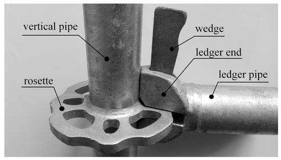
Figure 1.
A sample of a ringlock joint [16].
In another article by Kim et al., a new method has been suggested to improve the safety certification standards of mobile scaffolds [17]. In this type of scaffolding, the load-bearing capacity of the structure depends mainly on the assembly of some elements, including outriggers, caster wheels, horizontal and main frames, handrails, and braces to each other. This study has been done in Korea according to the standards. In their regulations, the load-bearing capacity of the scaffolds has been considered based on the load capacity of the elements separately. Therefore, there are many uncertainties in determining the load-bearing capacity of the mobile scaffold based on the strength of each element separately. In the study mentioned, structure-level criteria have been presented to observe the risk of overturning, the horizontal stiffness, and the load-bearing capacity of the structure. In this study the ultimate buckling capacity of the mobile scaffold frames has also been determined by applying the vertical loads to the vertical elements in four models, including mainframe, one-storey, two-storey, and three-storey frames. In the mentioned models, in addition to applying the vertical loads, side sway has been restricted. The deformation of the models has been shown in Figure 2 [17].
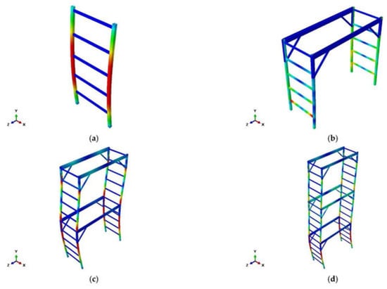
Figure 2.
Deformation of the models (a) mainframe, (b) one-storey mobile scaffold, (c) two-storey mobile scaffold, and (d) three-storey mobile scaffold [17].
In a paper presented by Pienko et al., the behaviour of the ringlock joint under different loads, including normal, bending, torsion, and shear forces, has been experimentally evaluated [16]. In this paper, normal, bending moment, torque, and shear forces were considered in the joints. The displacement was applied to the tests increasingly until the damaged or shattered model did not increase anymore, and the load-bearing capacity and stiffness of the joints were determined. The results also showed that stiffness during loading is less than during unloading [16].
In another study by Błazik-Borowa et al., the behaviour of the foundation of scaffoldings and stress in the elements under improper foundation construction has been numerically evaluated [1]. To consider the influence of uneven subsidence in the foundations, the stiffness in 50% of the supports has been considered variable. This matter caused an additional bending moment and normal stress in the support of the frame elements. However, the bracing and anchors of the scaffolds are negatively affected [1].
In a study by Pienko et al., the ringlock joints of the scaffolds have been experimentally evaluated [16]. In this research, the influences of horizontal and vertical shear force, normal force, moment force, and torque on the performance of scaffold joints have been used to calculate the load capacity of the connections. In this research, the stiffness of the joints has also been determined using four different approaches. In the experimental models, five models were tested, and the stress-strain curve of the joints was determined. In these models, the joint elements have been made of different materials. Experimental tests have been done to determine the areas of the joints that are under more stress. Since in scaffold design codes, there is no exact information about the design of the joints of these structures, the mentioned research has investigated the behaviour of the joints under shear, normal, and moment forces. The normal displacement control loading was applied to the standpipe or ledger and increased in each cycle until the models were damaged. The joint rosette element was damaged under normal force. Meanwhile, the weld connection between the rosette and the vertical pipe remained undamaged. The horizontal plane shear force was also applied to the joints. Joint stiffness was also observed during unloading and loading [16].
One weakness of scaffolding systems is the looseness of the scaffolding joints. Therefore, these parts of the scaffolds need reinforcement. Some solutions that have been presented so far are the use of braces and anchors in scaffolds. However, many scaffold structures still collapse, usually due to poor design and insufficient site supervision. When a thermal insulation layer has been used in the scaffold facade, the anchors cannot be fastened strongly. This will decrease the stability of the scaffolds. To solve this problem, long screws can be used in the anchors. However, this element is weak and can deform under wind forces; as a result, the surrounding insulation layer can also be damaged. To solve the above problems, a new type of façade anchor called a lever anchor is used. This anchor has been analysed experimentally and numerically, and the stiffness of these anchors was increased by adding some elements as braces, as shown in Figure 3. The results showed that displacement was restricted and decreased, stiffness increased, and stability improved. Another advantage of this system is the minimum displacement of the threaded bar, which prevents the insulation layer from being damaged. To make the numerical results consistent with the experimental results, in this research, the torsional stiffness was optimised [7].
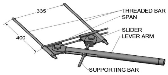
Figure 3.
Lever anchor [7].
In another paper, inner knee braces, planks, and anchor rods were used in scaffold systems to determine the load capacity of these systems under eccentric and concentric loads [18]. The results revealed that the use of anchor rods has increased the critical load of these structures by 1.5 times. This parameter also increased four times when plank and anchor rods were used in the scaffolds. It was also observed that the critical loads of scaffolds that have anchor rods in each storey are two times higher than those of scaffolds that have anchor rods in every two storeys. Therefore, the lateral stability of the scaffolds improved by using anchor rods. In this paper, small balls have been located at the bottom of the columns to make the scaffold system move. It was observed that when the load is subjected to the top of the scaffold, this part acts as a hinged support. This item was not found in other research and can be developed in our research. Because the basement of the columns had an important influence on the stability of the scaffolds and lateral displacement. Using the knee brace increased stiffness and improved buckling mode.
In another research done by Chandrangsu et al., some geometric imperfections of cuplock falsework include out-of-plumb eccentric load and frame [4]. Different joint configurations were evaluated to determine joint stiffness under bending moment and load in different directions. The vertical bending stiffness was observed to be greater than the horizontal one, and the stiffness of four-way connections was greater than that of other connections, including two-way and three-way connections. Stiffness and moment rotation of the sample about the z-axis are shown in Figure 4 [4].
Figure 4.
Moment-rotation of the sample [4].
In other research, the moment capacity of three different scaffold connections, including swivel, sleeves, and right-angled couplers, has been determined experimentally and theoretically. It was observed that the capacity to loosen the connection is affected by losses under cyclic loading. Also, this factor is high in all of the above connections, and, as a result, the stiffness of the connections is reduced. In the sleeve connection, the stiffness and maximum moment capacity of the coupler were affected by the axial load [19].
The load-bearing capacity of concrete anchors has been evaluated by Saleem et al. [20,21]. These systems can be used in temporary structures as support systems. In this paper, the pull load capacity of concrete anchors has been evaluated considering the rebound value of the Schmidt hammer. The concrete anchor is made of a concrete cylinder located in a structure that includes a support rod, a reaction rod, and an anchor that connects to the base plates (Figure 5) [20]. As a result, some effective factors in the load capacity of these elements are anchor diameter, embedment length, anchor alignment, and concrete strength. The results also showed that a wrong alignment of the anchors by more than 5% can decrease the load-bearing capacity. Furthermore, it was observed that the placement and compaction of concrete significantly affect the rebound value. Samples with poor concrete compaction have a lower rebound value and vice versa [20]. Schmidt hammers can be used to determine the compressive strength and hardness of the element by impacting the rock surface or concrete [22].
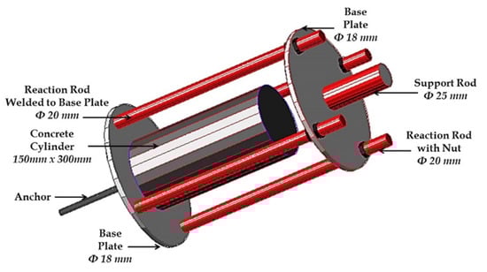
Figure 5.
3D schematic of the anchor cage [20].
In the investigation, the moment rotation capacity of the joint in cuplock and disc lock tubular scaffolds was evaluated in different configurations, including joint type, corrosion, height, and properties of the standing tube. The experimental results showed that in the cuplock joints of scaffolds, the initial stiffness and moment-rotation capacity are 2.9 and 1.8 times higher than those of the disc lock joints. The results also showed that initial stiffness and moment rotation capacity can be reduced by 50% as a result of corrosion [23]. After the moment capacity of the disc lock joint scaffold was exceeded, some plastic deformation and a hole occurred in the joint area, as shown in Figure 6 [23].

Figure 6.
Joint deformation of disc lock model: (a) plastic deformation; (b) pit on the element [23].
A numerical study on the rotational stiffness of the disc lock scaffold joint was performed using nonlinear finite element methods to determine the load-bearing capacity of the joint [24]. To this aim, different loading modes and geometric properties and configurations of the connection were also considered, including one-way, two-way, three-way, and four-way disc lock connections. Different loading conditions were also subjected to the scaffold element, as shown in Figure 7, in such a way that the models were loaded upward and downward [24]. The results showed that while the rotation angle of the models increased, the rotational stiffness first increased and then decreased due to the nonlinearity of the materials. It was also observed that the rotational stiffness of the models that the load was applied to is larger than that of downward, which is mainly due to the geometric properties of the joint [24].
Figure 7.
Loading setup of the models [24].
Another study of one type of joint, called loosely joined structures, has been done to determine the dynamic behaviour of the joints [25]. These joints have non-linear lateral behaviour under bending. The results showed that the periodic, quasiperiodic and chaotic response depends on the value of the joint damping [25]. Another study was conducted by Wang et al. on scaffold design using the reliability-based limit state design method [26]. Firstly, in this research, the finite element method has been used to determine the effective parameters of the ultimate load-bearing capacity of scaffolds. Then, a system reliability assessment was developed to estimate new design criteria of scaffolds based on the probable method of FORM [26].
Since the connections and joints of the temporary member structures (TMS) are the weakest part of these structures, a study of the joint stiffness and geometric imperfections of the plug-pin scaffolds has been performed by Liun et al. [27]. Multipoint displacement measurements of small joints are difficult; therefore, to increase the accuracy of the measurement, the vision-based measurement system has been used. Some factors, including semi-rigidity between bracing, upright rods, and horizontal bars, and compression and tension of the horizontal bar joint, have been evaluated to obtain the failure and load-bearing capacity of the models. The models were analysed under different load conditions, and the results showed that the geometric imperfections of the ATM systems with plug-pin joints are greater than those of the cuplock joints [27].
Błazik-Borowa et al. have researched the evaluation of the effects of incorrect foundation of façade scaffolds on element stress [1]. In this research, the heterogeneity of the ground was considered, and the behaviour of the scaffolds was evaluated in different conditions of the ground and the foundation, including mudsills and concrete. On the other hand, the influence of incorrect anchors and different boundary conditions of the foundation and anchors was also investigated [1].
Jia et al. [28] have evaluated the load capacity of tubular fastener scaffolds and truss-reinforced mortise and tenon scaffolds. In this paper, the behaviour of the mentioned joints has been experimentally analysed in different bracing conditions. The results showed that the top bracing of the fastener scaffolds resulted in a higher load-bearing capacity, and the joint displacement of the mortise and tenon scaffolds was less than that of the fastener scaffolds. The mortise-tenon and fastener joints are shown in Figure 8 [28].
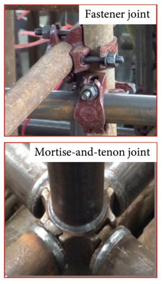
Figure 8.
Mortise-and-tenon and fastener joints [28].
The behaviour of the ledger-stand joints has been studied in the aluminium modular scaffolds in a study by Blazik-Borowa et al., in which two types of joints, including flexible and rigid joints, were evaluated [29]. To monitor the behaviour of cuplock scaffold joints and detect their looseness, a study was performed by Zhang et al., in which three shear piezoelectric transducers (PZTs) and three stress PZTs were installed on the cross and vertical bars of the mentioned joint (Figure 9) [30]. Then the signal energy between the PZTs and joints was analysed using the wavelet packet analysis method. The results showed that shear PZTs are better for monitoring the joints than stress PZTs. The results also proposed a sensor looseness index matrix (SLIM), and it was observed that when the looseness of the joint increases, the mentioned index also increases [30].
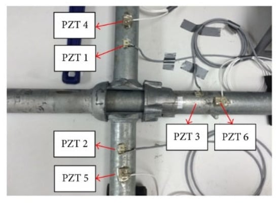
Figure 9.
Cuplock joint and PZT sensors [30].
Some recent studies have focused on the tensile, compressive, and bidirectional bending forces of the plug-pin joints of scaffold structures under various low temperatures, material properties, and geometric dimensions [31,32,33]. In another study, plug-pin scaffold joints made of stainless steel sorbite were evaluated under different loading types and dimensions [34]. In other research, the behaviour of the scaffold structure under the removal of the braces has been investigated [35]. Another study investigated steel falsework structures under various load eccentricities, bracing arrangements, and joint stiffness [36]. The effects of anchors and braces on the behaviour of facade scaffolds under dynamic loads were also examined in another study [37]. Influences of wind load on temporary structures have also been investigated in other research [38,39]. The structure of the socket-type scaffold and its joints have been evaluated experimentally and numerically, and the material properties of the pipe elements, joint stiffness, and bracing configurations have been evaluated [40]. In addition to investigating the mechanical properties of the scaffolds and their elements experimentally and numerically, some new techniques have also been developed to monitor and predict their behaviours and performance based on artificial intelligence techniques, including deep learning, sensor fusion, etc [41,42,43]. Another paper evaluated the static behaviour of façade scaffold structures under geometric imperfections in different configurations and dimensions [44].
3. Research Gaps, Aims of the Study, and Novelty of the Research
As mentioned above, although there are many studies on joints of scaffolds, a lot of studies are still required to be done on other types of joints. In addition, very little work was found on the anchors of the scaffolds. On the other hand, the influence of joints and anchors on the permeability and stability of scaffold structures is significantly important. It was found that one of the reasons for the unpredictable behaviour of the mentioned structures is the stiffness and mechanical properties of the elements of these structures. Among the previous studies, the lack of considering the influences and estimating the mechanical properties, including energy absorption and stiffness of anchors, on the stability and mechanical properties and behaviour of the scaffold structures is significantly important.
In other words, there is very little research on the influences of the mechanical properties of anchors (stiffness, energy absorption, etc.) on the mechanical behaviour (load-bearing capacity, maximum displacement) and stability of the scaffold structures. Moreover, there is very little research on evaluating the behaviour of anchors of the mentioned structures. Since one of the main sources of unpredictable behaviour of the scaffolds can be related to the mechanical properties, especially the stiffness of the anchors and joints, determining the mentioned properties of the mentioned elements in the scaffold structures can make a significant improvement in predicting the behaviour of the scaffoldings more accurately. As a result, the stability and safety of the mentioned structures could be improved significantly.
Therefore, in this research, the mechanical properties of joints and anchors have been extracted, including initial stiffness, energy absorption, ductility, load-bearing capacity, and maximum displacement based on the mechanical behaviour and force-displacement curve of previous studies. Taking into account the mentioned factors for the joints and anchors of the mentioned structures could make the mentioned structures more accurate and improve the safety, and stability and optimise the costs of design, execution, and construction of the mentioned structures. This study emphasises and highlights the effects and importance of the mechanical properties of anchors and joints on the stability and mechanical behaviour of the scaffold structures. Determining the mechanical properties of the anchors and joints provides a more comprehensive view of the effective factors on improving the behaviour, performance, and stability of the scaffold systems and expands our insights into designing the scaffold structures and their elements in a more accurate and predictable way.
The primary aim of this research is to systematically extract and analyse the mechanical properties of scaffold joints and anchors—including initial stiffness, energy absorption, ductility, load-bearing capacity, and maximum displacement—based on existing experimental and numerical studies. By quantifying these parameters, the study seeks to highlight their influence on the global behaviour and stability of scaffolding systems. Furthermore, the study aims to provide practical insights for optimising the design, execution, and safety of temporary scaffold structures used in both conventional and structural maintenance operations.
Although various European Standards such as EN 12811-1, EN 12810-1, and other parts of the Eurocode provide general design and performance requirements for scaffolding systems, couplers, and temporary structures, they do not offer detailed mechanical parameters for joints and anchors. These codes primarily focus on safety, geometry, and load classification but lack specific numerical values for key parameters such as stiffness, energy absorption, or ductility. This regulatory gap leaves scaffold designers and engineers without precise input data for simulations and safety assessments. Therefore, a major aim of this research is to emphasise this gap by compiling and reanalysing empirical mechanical data, thus enhancing the practical and normative foundation for design decision-making in scaffolding systems.
While many existing studies have focused on specific scaffold types or isolated joint behaviours, this research offers a novel synthesis by quantitatively comparing various types of joints and anchors through standardised mechanical performance metrics. Unlike previous works that mainly provided qualitative assessments or lacked consistent parameters, this study aggregates and standardises data from multiple sources to derive comparative values for energy absorption, stiffness, and ductility. In addition, the study uniquely emphasises the structural importance of scaffold anchors—which are often overlooked—and their role in supporting critical repair activities on structural elements. By indicating this gap, the study contributes a unified reference framework that can guide future experimental, numerical, and design efforts in the scaffolding field.
Furthermore, this research uniquely addresses a critical shortcoming in current engineering standards. Despite the presence of normative frameworks such as EN 74 and EN 12811, these standards fail to provide precise mechanical input parameters for joints and anchors under different loading scenarios. By emphasising this standardisation gap through the analysis of empirical force-displacement data, the study contributes not only to scientific knowledge but also lays the groundwork for enhancing and refining existing codes. This alignment between academic research and practical code development represents a key innovation of the study.
4. Methods
Anchors and joints can have a significant influence on the stability and behaviour of scaffold structures. On the other hand, estimating the mechanical properties and stiffness of the above elements has been one of the most important challenges because of their temporary nature. Therefore, to accurately predict and calculate the behaviour of scaffolds and improve their safety, it is crucial to determine the mechanical characteristics of anchors and joints.
In the current research, data from the results of recent studies have been obtained on the joints and anchors of scaffold structures. Data on mechanical characteristics include force-displacement curves and maximum load and displacement of the mentioned elements. The force-displacement curves presented in this study are redrawn from previously published works. Original sources are cited in each caption.
Some important factors, including initial stiffness, energy absorption, and ductility, have been determined based on the force-displacement curves of the models numerically. To this aim, data on the force-displacement curves have been extracted from the curves. The area under the mentioned curve was then estimated using Excel software, and energy absorption was determined, as this method is a common way to determine this factor in the European Standards [45]. In the next step, the equation of the above curve in the elastic area was estimated using Excel software, and the slope of the curve was considered as the initial stiffness. It is worth mentioning that this parameter is important in predicting and determining the behaviour of scaffoldings. Finally, the ductility of the models was discussed and compared with each other based on the ultimate displacement of the models.
4.1. Data Collection and Digitisation
The force-displacement graphs were extracted from published figures in peer-reviewed articles [16,23,31,33]. These plots were digitised using WebPlotDigitizer and processed in Microsoft Excel to obtain discrete numerical data points. This method allows estimation of critical mechanical parameters even when raw data are not publicly available.
4.2. Calculation of Mechanical Properties
The following key mechanical properties were derived from the digitised force-displacement data using numerical analysis in Microsoft Excel. Each parameter was estimated using a consistent methodology across different experimental datasets to allow comparative analysis.
4.2.1. Energy Absorption
Energy absorption (EA) represents the amount of energy absorbed by the joint or anchor during deformation, which corresponds to the area under the force-displacement curve. This parameter reflects the joint’s ability to dissipate energy before failure and is critical in evaluating structural resilience under dynamic or cyclic loading.
The area under the curve was calculated using the trapezoidal integration method in Excel, as follows:
: force values at consecutive data points (in kN)
: corresponding displacement values (in mm)
: total number of data points
This method was implemented through Excel’s spreadsheet environment by computing segment-wise areas between adjacent data points and summing the results. Energy absorption is expressed in joules (J), where 1 J = 1 kN·mm.
4.2.2. Initial Stiffness
Initial stiffness (denoted as K ratio) reflects the elastic rigidity of the joint or anchor and is defined as the slope of the force-displacement curve in its initial linear (elastic) region.
To estimate this value, the elastic segment of the curve was fitted with a linear equation (first-degree polynomial) using Excel’s trendline fitting tool. The equation took the form:
F: applied force (kN)
: corresponding displacement (mm)
K: initial stiffness (kN/mm), which is the slope of the line
C: intercept (usually close to zero in well-behaved elastic responses)
The slope K obtained from this linear equation was recorded as the initial stiffness. This method allows objective and repeatable quantification of stiffness based on actual data behaviour in the elastic range.
In order to infer the initial stiffness and compare them in different models, this factor has been multiplied by the maximum displacement and divided into the maximum load-bearing capacity of the models. As a result, the relative stiffness of each system has been determined. This factor is dimensionless and makes it possible to compare the initial stiffness in different elements of the scaffold structures regardless of their configuration and dimensions. This non-dimensional parameter reflects the relative contribution of the elastic stiffness to the overall load-bearing capacity of the system. A higher value of this factor indicates that the element behaves in a stiffer and more rigid manner relative to its ultimate strength, whereas a lower value highlights greater deformability and a more ductile response before failure. By eliminating the effect of absolute dimensions and loading levels, this relative stiffness index provides a practical means for comparing different scaffold elements and understanding the inherent trade-off between stiffness, ductility, and energy absorption. Such an approach offers useful insight for evaluating the performance of various joint and anchor types under different design scenarios.
4.2.3. Ductility
Ductility () represents the deformability of the joint or anchor beyond yielding and is a key indicator of its ability to undergo plastic deformation without brittle failure. It was estimated using the following ration:
: ultimate displacement (displacement at peak load)
: yield displacement (displacement at which elastic behaviour transitions to plastic)
Where the yield point was not explicitly available in source studies, it was estimated visually from the curve’s deviation from linearity or inferred from the end of the initial linear segment. In cases where yielding was gradual, a consistent inflection criterion was applied.
This approach enables qualitative and quantitative comparison of joint performance under large deformations and supports safety-based evaluations in scaffold system design.
4.3. Comparison and Standardisation
For consistency, all computed values were compared across multiple studies and normalised where necessary (kN·mm). The extracted data were visualised as comparative graphs and tables to identify performance trends among joint types (e.g., plug-pin, ringlock, wheel coupler) and anchor configurations.
This methodological framework ensures reproducibility and allows for reliable performance benchmarking across a wide range of scaffold connection types.
5. Results and Discussion on Mechanical Properties and Behaviour of Scaffold Anchors
Mechanical Behaviour of Lever Anchors
As mentioned, in the study by Ilcik et al., an updated anchor of scaffolds has been presented [7]. In the proposed methods, the anchor has been stiffened by the oblique arms as shown in Figure 10 [7]. This decreased displacement, and the stability of the lever anchor has been improved significantly. Moreover, to make sure that the anchor would not damage the insulating layer of the façade of the buildings, a little deformation is allowed in the connection of anchor bars to the building. Dimensions of the arm and elements have been optimised, and the anchor has been modelled and analysed numerically with beam, solid and enhanced solid elements. To this end, the lever arm has been subjected to tensile and compressive force, and the force-displacement curve of the model under tension is shown in Figure 11. To extract the energy absorption of the anchors, the force-displacement curve of the FE2-Solid element under tension has been redrawn, and the data have been extracted (Figure 12). For the mentioned model, energy absorption is 45.08 J, and the maximum load-bearing capacity is 17.91 kN in the corresponding displacement of 13.61 mm. Although the most accurate model among the above three models is an anchor with an enhanced solid element, the solid element has been considered to obtain energy absorption because this type of element is a 3D element that is closer to reality.
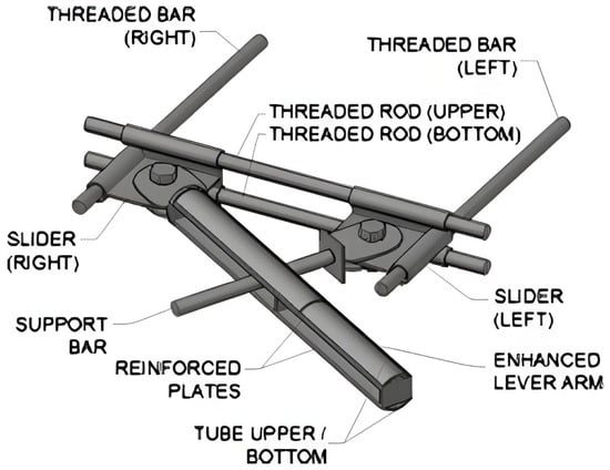
Figure 10.
The optimised and updated lever arm of the anchor [7].
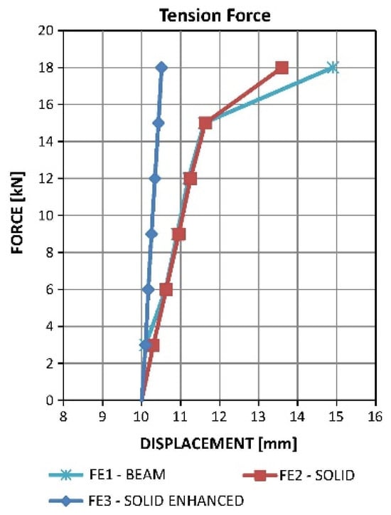
Figure 11.
Force-displacement curve of the anchor in different element types under tension [7].
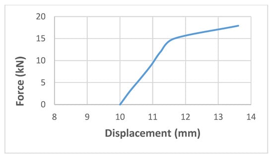
Figure 12.
Redrawn force-displacement curve of the FE2 solid anchor under tension [7].
The force-displacement curve of the FE2 solid lever anchor under linear behaviour is illustrated in Figure 13. The equation of this curve is estimated in Excel software.
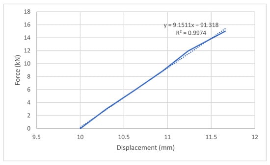
Figure 13.
Force-displacement curve of the FE2 solid model in linear behaviour.
The initial stiffness of the lever anchor was obtained by fitting a linear regression line to the elastic region of its force-displacement curve. The fitted equation is:
In this equation:
y: denotes the applied force (kN),
x: represents the corresponding displacement (mm),
The coefficient 9.1511 is the slope of the line, which directly reflects the initial stiffness of the anchor in the elastic range (kN/mm), and the constant term –91.318 is the y-intercept. which has no physical significance in the context of stiffness but results from the curve fitting process, and the coefficient of determination, 0.9974, indicates an extremely high degree of linear correlation and fit quality between force and displacement in the elastic region and the trendline.
A high value, close to 1, suggests that the linear model explains over 99.74% of the variation in the force data, confirming the suitability and precision of the linear fit. Therefore, the slope of the fitted line, 9.15 kN/mm, is a reliable and valid estimate of the elastic stiffness of the lever anchor model. This method ensures both reproducibility and accuracy, as the stiffness is derived objectively from the actual behaviour of the joint and not based on assumed parameters. The curve fitting was performed using Excel’s trendline function, and the regression model was visually and statistically validated before final stiffness values were adopted. Considering the maximum load-bearing capacity of 17.91 kN and maximum displacement of 13.61 mm for this model, the relative stiffness is 6.95. This indicates that using the bracing systems in the anchor of scaffold systems can make them more rigid.
In the next step, the lever arm is subjected to compression. At this stage, an initial geometric imperfection was considered in the anchor, and the FE4 model was defined. This imperfection has been made in the solid model by considering a gap between the elements. The force-displacement curve of the anchor models with different types of elements, including solid and beam, is shown in Figure 14 [7]. It can be observed from Figure 11 and Figure 14 that the enhanced solid model in tension and compression and the solid model with geometric imperfections showed linear force-displacement curves. To extract the energy absorption of the model, the FE2-Solid element has been chosen because this element type is more similar to reality, but in compression, the most accurate model is also the FE4 model. Therefore, the force-displacement curve of the anchor with the FE2-Solid element has been redrawn and shown in Figure 15. Energy absorption in this model has been determined to be 68.73 J, which is 52.46% higher than in tension.
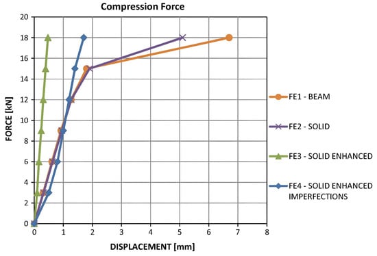
Figure 14.
Force-displacement curve of the anchor in different element types under compression [7].
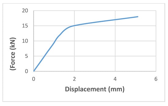
Figure 15.
Redrawn force-displacement curve of the FE2-Solid element anchor under compression [7].
The linear regression analysis performed on the elastic portion of the force-displacement curve for this model resulted in the equation y = 9.3483x + 0.0046, with an value of 1.000 (Figure 16). This perfect correlation confirms that the relationship between force and displacement in the elastic region is entirely linear and free from deviation or experimental noise.
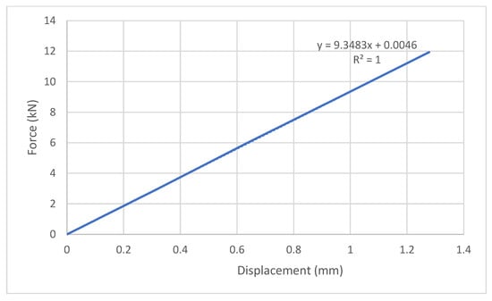
Figure 16.
Force-displacement of the lever anchor under compression in the linear part.
Accordingly, the initial stiffness of the FE2-Solid anchor model is accurately determined as 9.35 kN/mm, based on the slope of the fitted line. The use of linear regression ensures that this stiffness value is both statistically valid and mechanically representative. The perfect goodness-of-fit (R2 = 1) further strengthens the reliability of the extracted stiffness, indicating that the data points align exactly along the fitted trendline in the elastic domain. Such precision in stiffness estimation is essential for predictive modelling and safety assessment of scaffold connections.
The FE2-Solid model of the anchor shows a better behaviour of the anchor under compression. Furthermore, this model presented a maximum load-bearing capacity of 18 kN in the corresponding displacement of 5.11 mm. Therefore, it is found that the maximum load-bearing capacity of the FE2-Solid model is almost the same in tension and compression; meanwhile, the maximum displacement in compression is 62.45% less than in tension. Relative stiffness in this model has been determined by 2.65. This shows that the model under compression is less rigid and more flexible than under tension. Since the tensile behaviour of anchors is more important than their compressive behaviour, this type of anchor has more rigidity under tension compared with compression.
The results also showed a permanent deformation in the anchor; meanwhile, all elements of the anchor under tension and compression illustrated the stress of less than yielding. Moreover, it was observed that after updating the material properties and stiffnesses in the finite element models, the force-displacement curves became consistent with the experimental results [7]. To compare the results of different models, including energy absorption and load-bearing capacity, the force-displacement curves have been compared with each other (Figure 17). Since solid elements are more similar and consistent with reality, the results of these elements in the above curve have been considered and redrawn as shown in Figure 18.

Figure 17.
Comparison of the beam and solid elements of the updated anchor with the experimental model [7].
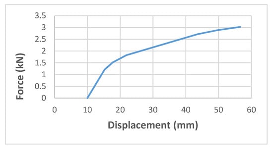
Figure 18.
Redrawn force-displacement of an updated solid numerical model of a lever anchor [7].
Based on the redrawn curve above, the updated finite element model presents the maximum load capacity of 3.02 kN in the corresponding displacement of 56.59 mm. Therefore, the energy absorption of this model, which has been extracted from the area under the referred curve [45], is 100.19 J. The initial stiffness in the elastic area for the mentioned model, which is illustrated in Figure 17, is 0.23 kN/mm. However, the important point is that the stress value in all lever anchor materials after analysis is below the yield stress value.
The elastic behaviour of this model was characterised by a linear regression equation of y = 0.2292x − 2.2882 with a perfect correlation coefficient of 1.000 (Figure 19). The slope of the regression line, 0.2292 kN/mm, represents the initial stiffness of the joint, which is significantly lower than the other evaluated models. This indicates that the connection is relatively flexible and undergoes large displacements even under small, applied forces. Relative stiffness in this model has been calculated at 4.31, which shows a rigid behaviour in the updated finite element model of the lever anchor.
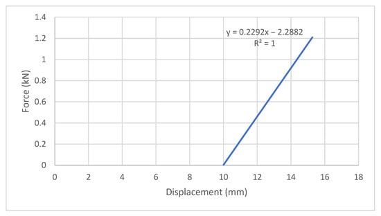
Figure 19.
Force-displacement curve of the updated solid numerical model of the lever anchor.
This behaviour may be desirable in scenarios where energy dissipation and deformability are prioritised over rigidity. However, the low stiffness also implies potential limitations in load-bearing capacity and lateral stability, which should be taken into account in practical applications.
Such observations highlight the need to tailor scaffold joint selection to project-specific performance requirements, where both stiffness and ductility must be balanced depending on the structural context.
6. Results and Discussion on Mechanical Properties and Behaviour of Ringlock Joints of the Scaffold Structure
As mentioned in the review of the literature, the joints of ringlock scaffold structures have been examined and analysed experimentally [16]. In this study, the load has been applied to the joint shown in Figure 1 in different ways, including normal, shear and torsional force. In addition, the shear force and the bending moment have been considered in two planes. The results showed that in the case of normal force, the joint was damaged in the rosette element (Figure 1) as a result of the shear force in the connection of the wedge to the opening of the rosette. Force-displacement curves of the elements of joints are shown in Figure 20. To extract the energy absorption and maximum load capacity and displacement, the average force-displacement curves, which are shown in Figure 20, have been redrawn and shown in Figure 21.
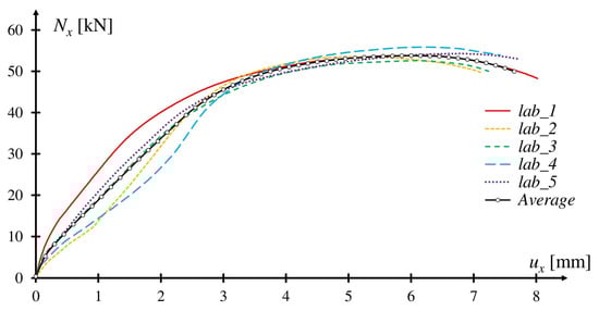
Figure 20.
Normal force-displacement curve of the joint models [16].
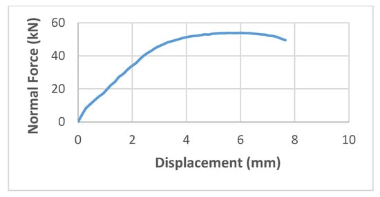
Figure 21.
Average redrawn normal force-displacement curve of the experimental model under normal force [16].
In the above curves, it can be observed that the maximum force of the model is 49.48 kN in the corresponding displacement of 7.65 mm, which presents an energy absorption of 319.65 J. The initial stiffness in this model is 15.86 kN/mm in the elastic zone, which shows that this model has the highest initial stiffness compared to other models discussed in this paper. The linear regression applied to the elastic portion of the force-displacement curve yielded a stiffness value of 15.86 kN/mm, indicating a relatively rigid response in the initial loading phase (Figure 22). The coefficient of determination of 0.9934 reflects a strong linear relationship between force and displacement, confirming that the estimated stiffness is reliable and representative of the actual mechanical behaviour. While not perfect, this level of fit still validates the use of linear modelling in this range and supports the accuracy of the extracted stiffness parameter. Relative stiffness in this model is 2.45, which shows a more flexible behaviour compared with the updated finite element model of the lever anchor. This flexibility can be a positive option in dissipating the energy and stability of the joint under normal force.
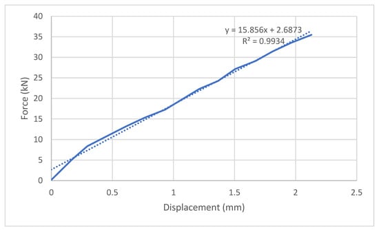
Figure 22.
Force-displacement curve of the ringlock scaffolding joint under linear normal force.
Therefore, the energy absorption in this joint is 219.04% more than in the lever anchor. Another load that was applied to the joint is the shear force in the plane of the scaffolding platform (horizontal plane). This type of loading can also occur in the anchors, so the results of the mentioned loading can be compared with the lever anchor. The shear force-displacement curve of the ringlock joint is illustrated in Figure 23. The loading has been continued until the displacement of 10 mm and the corresponding load-bearing capacity of around 30.43 kN. It can be observed that after the 6 mm displacement, the models strengthened as a result of resting the side elements of the wedge on the opening edge at the end of the ledger. The mean shear force-displacement curve has been redrawn and shown in Figure 24. This curve presented an energy absorption of 169.86 J, which is 69.53% more than the lever anchor. Analysis of the elastic segment of the force-displacement relationship produced a regression line with a slope of 4.04 kN/mm, suggesting a moderate initial stiffness compared with other tested configurations (Figure 25). The coefficient of determination of 0.9908 indicates that the linear model explains over 99% of the variation in the measured data, confirming the robustness of the fit despite minor scatter in the experimental points. This level of stiffness reflects a balance between rigidity and deformability, which could be advantageous in situations where controlled flexibility is required to mitigate localised stress concentrations while still maintaining structural stability. Moreover, relative stiffness in this model is estimated by 1.33. This shows that the mentioned joint is more flexible under shear force compared with normal force.
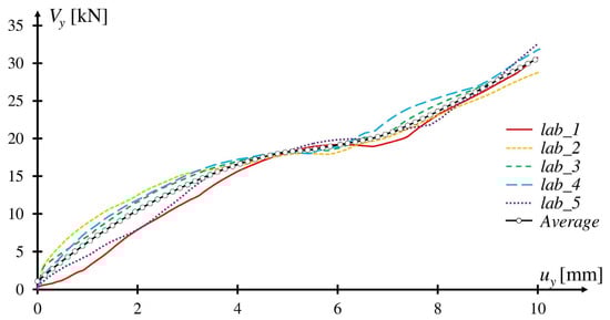
Figure 23.
Horizontal shear force-displacement curve of the joint [16].
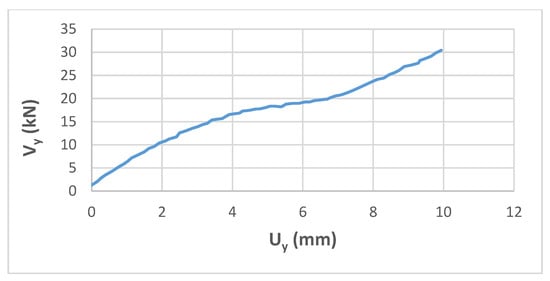
Figure 24.
Average shear force-displacement of the model [16].
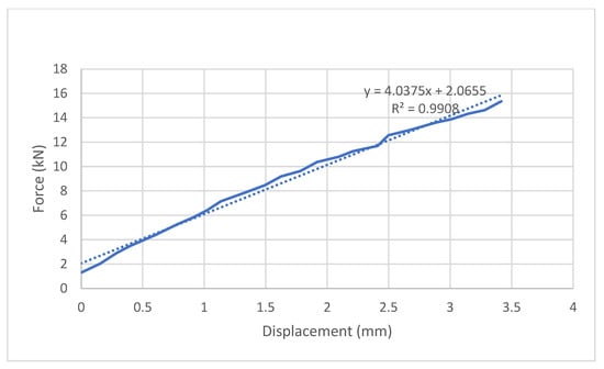
Figure 25.
Force-displacement of the ringlock scaffold joint under linear shear force.
7. Results and Discussion on Mechanical Properties and Behaviour of Wheel Coupler Joints of Scaffold Structure
Another study on the evaluation of the behaviour of joints in the wheel coupler scaffold structures was proposed by Jia et al. [46]. To this end, the rotational stiffness of the joints has been determined in symmetric, asymmetric, and unilateral bilateral under compression and tension forces. These forces are usually very similar to the forces that are imposed on the joints in reality. It was found that in addition to having non-linear joint behaviour, the failure was better reflected in the deformation of the wheel coupler joints under bilateral symmetric compression and tension state loads. The results showed that the maximum stress has been distributed in the area between the plate and the wheel coupler plug in bilateral symmetric, bilateral asymmetric and unilateral tensions. Therefore, the failure occurred at the edge of the plate socket of the wheel coupler, and the plug has been deformed in the bilateral symmetric tension as shown in Figure 26, and this model presented better results compared to other models under tension. In this model, the serviceability and the maximum load limit state are 20 kN and 35 kN, respectively. In compression, compression deformation was observed to be better reflected in the bilateral symmetric model, and in this model, the maximum stress occurred in the contact area of the upper part of the plug and the upright tube, as shown in Figure 27. The maximum force-displacement curve of the bilateral symmetric model under tension in the x-axis of the plug is shown in Figure 28. In this curve, the energy absorption of the model based on the subjection of the load on the x-axis of the plug has been extracted by 259.4 J, and the initial stiffness has been extracted from the linear force-displacement curve of the model, which is illustrated in Figure 29. The regression analysis of the elastic range yielded a slope of 12.43 kN/mm, indicating a relatively high initial stiffness and a strong resistance to deformation under early-stage loading. Such stiffness characteristics are advantageous in applications where minimal deflection is required, although they may also imply reduced ductility compared with more flexible joint configurations. With respect to the maximum load-bearing capacity of 35 kN and the corresponding displacement of 10.64 mm, relative stiffness in this model is 3.78, which shows that this joint is less flexible and more rigid than the ringlock joint of the scaffold, which was presented in the previous part.
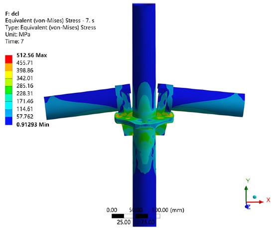
Figure 26.
Maximum stress in the bilateral symmetric model under tension [46].
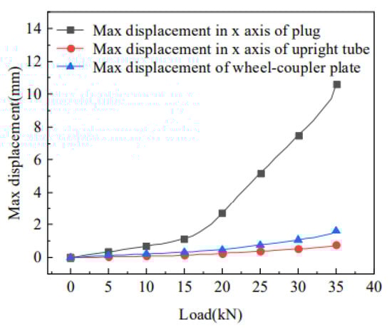
Figure 27.
Force-displacement curve of the bilateral symmetric model under tension [46].
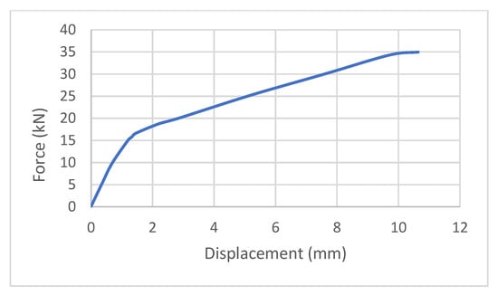
Figure 28.
Force-displacement curve of the wheel coupler connection of the scaffold system in the x-axis of the plug [46].
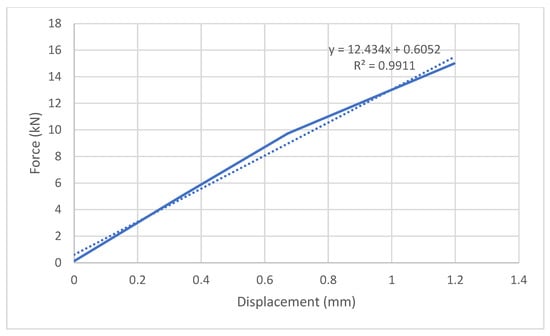
Figure 29.
Force-displacement curve of the wheel coupler joint under static load in the x-axis of the plug.
Since the subjected tension load can be categorised as a normal load in general (and not a shear or torsional load), it would be preferable to compare the energy absorption of this model with the joints or anchors that are subjected parallel with the axis of the elements (normal forces). Such conditions have been found in the study of the joints of ringlock scaffolds [16]. As mentioned before, the energy absorption of the mentioned joint has been determined at 319.65 J, which is 23.23% more than the bilateral symmetric wheel coupler under tension [46].
In compression, it was observed that compression deformation was better reflected in the bilateral symmetric model, and in this model, the maximum stress occurred in the contact area of the upper part of the plug and the upright tube, as shown in Figure 30 [46]. No significant deformation was found in the plug and wheel coupling under compression, and the serviceability and maximum load limit state for this model are determined by 35 kN and 45 kN, respectively.
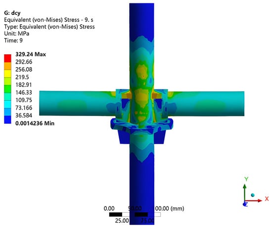
Figure 30.
Maximum stress in the bilateral symmetric model under compression [46].
8. Results and Discussion on Mechanical Properties and Behaviour of Plug-Pin Joints of Scaffold Structure
As mentioned before, the Q355 joint and sorbite stainless steel models have been analysed at different temperatures [31]. The force-displacement curve of these models is shown in Figure 31. Since the LQ-40 model with Q355 material showed more ductile behaviour and more load-bearing capacity at -40 degrees Celsius, this model is considered to calculate energy absorption. It was observed that the above model has an energy absorption of 494.83 J, which is the highest energy absorption among the other models discussed. Furthermore, the maximum load-bearing capacity of this model is 42.32 kN in the corresponding displacement of 15.5 mm. This model also has an initial stiffness of 8.76 kN/mm. This stiffness has been presented and determined in the paper. Relative stiffness in this model is 3.21.
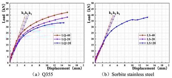
Figure 31.
Force-displacement curve of Q355 model, (a) Q355 material, (b) sorbite stainless material [31].
In addition to different temperatures, the models were also numerically analysed in different thicknesses of C-type and U-type plates, different vertical pipe wall thicknesses, and different wedging depths of the joints. The results illustrated that increasing the thickness of U-type plates increased the tensile load-bearing capacity of the joint by 6.78%, and increasing the thickness of the C-type plate increased the tensile load-bearing capacity of the node by 6.25%.
Another similar research that was mentioned in the previous section of this paper was carried out on the compressive behaviour of the plug-pin joints of the scaffoldings at low temperatures [33]. In this research, six models have been analysed at different temperatures (−40 °C, −20 °C, and +20 °C) and different material properties. The findings showed that the stiffness of the models increased as the temperature decreased. The compressive force-displacement curve of the above models is shown in Figure 32. In the joint called the YQ-40 model, energy absorption under compression is 315.54 J. This model showed that the maximum compressive load-bearing capacity is 45.22 kN in the corresponding displacement of 4.82 mm. In this model, the initial stiffness of the elastic behaviour is 23.75 kN/mm. Based on these data, the relative stiffness of the YQ-40 model is 2.53, which illustrates that compared with the previous model, which has been performed under tension, the model under compressive force has more flexibility and less rigidity.
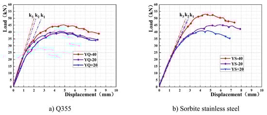
Figure 32.
Compressive force-displacement curve of plug-pin joints in different temperatures [33]; (a) Q355 model (b) sorbite stainless steel model.
On the other hand, the YS-40 model showed the maximum compressive load-bearing capacity, while, the YS-20 model showed more ductility. The energy absorption in compression in the YS-40 model appears to be 303.6 J, and the maximum compressive load-bearing capacity of this model is 52.98 kN in the corresponding displacement of 4.08 mm. Furthermore, this model showed an initial stiffness of 19.71 kN/mm in the elastic zone. It can be observed that the initial stiffness of the QS-40 model is 20.5% higher than that of the YS-40 model. On the other hand, the energy absorption of the QS-40 model is also 3.93% more than that of the YS-40 model. Moreover, relative stiffness in this model is 1.52. This shows the most flexibility and least rigidity compared with the mentioned joints and anchors that have been discussed above. It can be concluded that the plug-pin joint of the scaffold under the temperature of −40 degrees and the material of sorbite stainless steel has the highest flexibility. However, it is still unknown which factor in the mentioned model caused such high flexibility. In other words, it is not obvious that relative stiffness is related to the temperature, joint type, material properties, or other factors. Therefore, in order to determine the effective factors on the relative stiffness and provide more validated data for the gaps in Eurocode, more research is required, and the influences of each parameter should be determined separately in the future studies.
The results also showed that as the number of U-shaped plates, pipe wall thickness, and U-shaped plate thickness increased, the maximum load-bearing capacity and initial stiffness in the elastic area also increased, probably because the load-bearing capacity increased as a result of an increase in the cross-section area of the models [33]. In the model with the maximum number of U-shaped plates (4 plates), the maximum load-bearing capacity seems to be 55.03 kN in the corresponding displacement of 3.1 mm. In this model, the initial stiffness in the elastic area and energy absorption are probably 55.89 kN/mm and 376.92 J. The mentioned data shows the relative stiffness of 3.15 in the model with the number of four U-shaped plates. This means that increasing the number of plates can increase the rigidity and decrease the flexibility. However, in order to determine the limitations regarding configurations and corresponding relative stiffness of the plug-pin joints of the scaffold structures and provide some regulations for Eurocode, more research is required in the future.
On the other hand, in the joint with a maximum thickness of the pipe wall (3.5 mm), the maximum load-bearing capacity might be 42.14 kN in the corresponding displacement of 3.8 mm. Moreover, the initial stiffness in the elastic area and energy absorption can be 20.5 kN/mm and 269.94 J, respectively. Therefore, the relative stiffness of this model is estimated by 1.85.
Models with different U-shaped plate thicknesses showed that the maximum load-bearing capacity of the model with the maximum plate thickness (5.5 mm) is probably 50.6 kN at the corresponding displacement of 5.2 mm. Energy absorption and initial stiffness in elastic behaviour are also 315.47 J and 19.2 kN/mm, respectively. Therefore, the joint model with four U-shaped plates with 5 mm thickness and 3.5 mm pipe wall thickness can be a good option for execution. However, the mentioned dimensions can also be optimised in future studies. Relative stiffness in the model with the plate thickness of 5.5 mm is 1.97, which shows that increasing the thickness of the plates by 57% can increase the relative stiffness and rigidity and decrease the flexibility of the model by 6.5% and make the model more rigid.
As explained in the beginning, another experimental study on plug-pin joints of scaffolds with sorbite stainless steel material has been performed by Xie et al. [34]. In the joint tensile test, two bars were installed and welded to the C-shaped latch instead of the ledger (Figure 33), and displacement-control loading was applied to them until the joint was damaged. The force-displacement curve of the models in different dimensions and material properties is shown in Figure 34. The results showed that the wedge of KL48-2, KL48-3 and KL48-5 failed as a result of torsion and bending. The average curve presented an energy absorption of 63.85 J, a maximum force of 20.58 kN, and a corresponding displacement of 5.27 mm. Moreover, the initial stiffness in the elastic area of the curve has been extracted from the curve, which is 5.35 kN/mm. Consequently, the relative stiffness of this model is 1.37. It can be concluded that, in this case, plug-pin scaffold joints are more flexible and less rigid than wheel coupler and ringlock scaffold joints. However, it is not a general role and cannot be generalised to other plug-ping scaffold joints. Because, as mentioned, more studies are required to determine the effective parameters of plug-pin scaffold joints in relative stiffness.
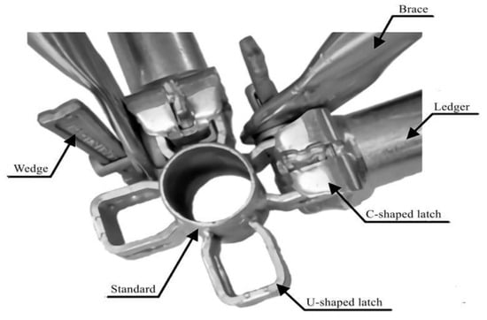
Figure 33.
Plug-pin joint of scaffolding [34].
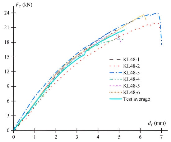
Figure 34.
Tensile-force displacement curve of the joint [34].
9. Results and Discussion on Mechanical Properties and Behaviour of Falsework Structure with Cuplock and Ringlock Joint Under Different Bracing and Loading Conditions
As mentioned, cuplock and ringlock joints have been analysed on different bending axes, load directions, and load values (the number of hammers locking). In addition, the influence of the type of loading (eccentric and concentric), bracing, edge situations, and spigot connections on the behaviour of cuplock and ringlock falsework structures [36]. The U-jack was observed to fail as a result of rotation and bending. Furthermore, an unstable end restraint in the upper part of the vertical tube caused significant bending. On the other hand, in all frames, the initial failure mode was mainly caused by the lower vertical tube being buckled in the area near the spigot connection. The force-displacement curve of the experimental tests of the falsework system is shown in Figure 35. It can be observed that test 4, the system with cuplock joints without bracing under concentric loading conditions, has the highest maximum deflection (20.32 mm), and test 5, the structure with ringlock joints under concentric loadings and with full bracings, showed the highest initial stiffness and ultimate load capacity. In this mode, the stiffness in the elastic area and the maximum load-bearing capacity are 67.12 kN/mm and 10.9 tonnes, respectively. In this model, maximum displacement is around 5.6 mm. As a result, the relative stiffness of this model is 3.46. Therefore, it can be observed that using full bracing systems for ringlock scaffold joints under concentric loading can make them more rigid and less flexible. This shows that the mentioned type of scaffold joint is more rigid and less flexible than the plug-pin and ringlock joints of the scaffold systems that have been discussed above. However, it is limited to this study, and it cannot be generalised to all of the plug-pin or ringlock scaffold joints, and more research is required to determine and develop Eurocode in the future under various effective parameters. After calculating the energy absorption of the models, it was observed that the test 4 structure might have the highest energy absorption among the other models, which is 1481.01 J.
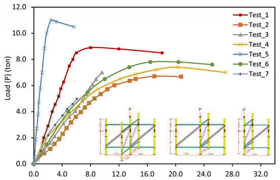
Figure 35.
Force-maximum lateral displacement curve of the falsework systems [36].
In summary, the interaction of stiffness, ductility, and load-bearing capacity should be considered as an integrated framework in scaffold design. It was found that, in addition to load-bearing capacity, other mechanical characteristics such as stiffness and ductility play a decisive role in the overall performance of scaffold systems and their critical elements, including joints and anchors. Stiffness strongly influences displacement control and global stability, whereas ductility determines the ability of joints and anchors to absorb energy and prevent brittle failure under dynamic or unexpected loads. A design that considers only load-bearing capacity may therefore overlook these critical aspects, which can significantly affect both safety and serviceability. The balance between stiffness and ductility is particularly important: while higher stiffness reduces deflections, excessive rigidity may diminish energy absorption, whereas greater ductility enhances resilience but may compromise immediate stiffness requirements. A summary of the evaluated factors in the previous studies is indicated in Table 1.

Table 1.
Comparative summary of joint and anchor performance characteristics.
These interactions highlight the necessity of considering multiple parameters simultaneously in scaffold design. Although stiffness, energy dissipation, and load-bearing capacity are highly dependent on the type and configuration of anchors and joints, they are not the only effective factors. Additional influences such as element dimensions, material properties, boundary conditions, frictional behaviour, and even environmental factors (e.g., corrosion or temperature variations) can markedly alter the mechanical response of scaffolding components. Therefore, identifying the relative impact of these parameters on the mechanical properties of different anchor and joint types and addressing the current shortcomings of Eurocode provisions requires extensive further research. More detailed experimental and numerical investigations are necessary to establish practical design thresholds for stiffness, ductility, and related properties, which will be pursued in future stages of this research.
Moreover, beyond the numerical results, several external factors should also be considered when applying these findings to real-world scaffold design. For instance, temperature variations can alter the stiffness and ductility of joints, as shown in recent studies on plug-pin connections at low temperatures. Corrosion or surface wear due to environmental exposure can reduce both load-bearing capacity and energy absorption over time. Moreover, construction tolerances, imperfect installations, and repeated cyclic loading in practice may lead to deviations from the idealised laboratory performance. Therefore, while the comparative summary presented here provides useful benchmarks for designers, safety margins and durability considerations must be incorporated in practical applications.
10. Conclusions
This study systematically analysed and synthesized experimental data from previous research to evaluate the mechanical properties of scaffold joints and anchors, with emphasis on energy absorption, ductility, initial stiffness, load-bearing capacity, and maximum displacement. The results highlight that joints and anchors, as the most sensitive elements of scaffolding systems, play a decisive role in determining overall stability and safety.
The findings revealed that joints with higher initial stiffness exhibited significantly lower displacements, thereby improving global stability. Plug-pin joints demonstrated superior energy absorption and ductility, whereas lever anchors were more effective under compression due to their bracing configuration. Bracing arrangements and anchor design were shown to substantially influence mechanical performance, confirming that optimisation of these elements can enhance both safety and cost-effectiveness in scaffold design.
From a practical perspective, the quantified mechanical parameters provide valuable input data for design optimisation, safety assessment, and potential code development, where current Eurocode provisions lack detailed guidance on stiffness, ductility, and energy dissipation of scaffold connections.
Additionally, this study proposed a dimensionless relative stiffness index, defined as the ratio of initial stiffness to ultimate load and displacement capacity, which enables a fair comparison among different joint and anchor types irrespective of their geometry and loading conditions. This parameter proved effective in distinguishing the balance between stiffness and ductility across various systems, and it can serve as a useful benchmark for future scaffold design and code development.
Overall, the results highlight that joint and anchor selection should be based on the required balance between stiffness and ductility: ringlock systems are preferable where displacement control and stability are prioritised, while lever anchors and cuplock joints may be more suitable in scenarios where ductility and energy dissipation are critical. These insights provide practical benchmarks for improving scaffold safety and could contribute to future refinements of Eurocode provisions.
However, the present findings cannot be taken as definitive reference values for the mechanical properties and behaviour of scaffold joints and anchors, nor as a direct solution to the current gaps in Eurocode provisions. This is because the relative stiffness and other mechanical parameters are influenced by multiple interacting factors, such as joint type, geometric configuration, material properties, and even environmental conditions. In this study, it was not possible to isolate and quantify the effect of each parameter individually. Therefore, future research should be conducted in a systematic manner, where key parameters are controlled and varied one at a time, to provide more validated data and establish reliable design thresholds. Such studies are essential for a comprehensive understanding of scaffold joint behaviour and for narrowing the regulatory gaps in existing standards.
Future research can focus on incorporating the identified mechanical parameters into both numerical and experimental studies, with the aim of establishing clear design thresholds and behavioural limitations for scaffolding joints and anchors. Such studies would help highlight the current regulatory gaps and provide more reliable input data for code development and practical design guidelines. Addressing these gaps will not only refine scaffold design methodologies but also contribute to enhancing the reliability and predictive accuracy of structural performance models.
Author Contributions
Conceptualization, A.R.; methodology, A.R.; software, A.R.; validation, A.R., D.C. and M.P.; formal analysis, A.R.; investigation, A.R.; resources, A.R.; data curation, A.R.; writing—original draft preparation, A.R.; writing—review and editing, A.R.; visualisation, A.R.; supervision, D.C. and M.P. All authors have read and agreed to the published version of the manuscript.
Funding
This research received no external funding. The article processing charge (APC) was co-funded by Lublin University of Technology (FD-20/IL-4/039) and Wroclaw University of Technology through the Financing Publication Costs 2025 programme.
Institutional Review Board Statement
Not applicable.
Informed Consent Statement
Not applicable.
Data Availability Statement
The raw data supporting the conclusions of this article will be made available by the authors on request.
Conflicts of Interest
The authors declare no conflict of interest.
References
- Błazik-Borowa, E.; Jamińska-Gadomska, P.; Pieńko, M. Influence of foundation quality on the stress in the elements of steel façade scaffolding. Buildings 2020, 10, 130. [Google Scholar] [CrossRef]
- Liu, H.; Jia, L.; Wen, S.; Liu, Q.; Wang, G.; Chen, Z. Experimental and theoretical studies on the stability of steel tube–coupler scaffolds with different connection joints. Eng. Struct. 2016, 106, 80–95. [Google Scholar] [CrossRef]
- Chandrangsu, T.; Rasmussen, K.J.R. Geometric imperfection measurements and joint stiffness of support scaffold systems. In Proceedings of the Sixth International Conference on Advances in Steel Structures, Hong Kong, China, 16–18 December 2009. [Google Scholar]
- Chandrangsu, T.; Rasmussen, K.J. Investigation of geometric imperfections and joint stiffness of support scaffold systems. J. Constr. Steel Res. 2011, 67, 576–584. [Google Scholar] [CrossRef]
- Beale, R.G. Scaffold research—A review. J. Constr. Steel Res. 2014, 98, 188–200. [Google Scholar] [CrossRef]
- Błazik-Borowa, E.; Bęc, J. Influence of dynamic properties on scaffoldings safety. Arch. Civ. Mech. Eng. 2021, 21, 144. [Google Scholar] [CrossRef]
- Ilcik, J.; Arora, V.; Dolejs, J. Design of new scaffold anchor based on the updated finite element model. Eng. Struct. 2016, 118, 334–343. [Google Scholar] [CrossRef]
- EN 12811-1; Temporary Works Equipment–Part 1: Scaffolds–Performance Requirements and General Design. British Standard: London, UK, 2003.
- Nowobilski, T.; Hoła, B. Methodology based on causes of accidents for forcasting the effects of falls from scaffoldings using the construction industry in Poland as an example. Saf. Sci. 2023, 157, 105945. [Google Scholar] [CrossRef]
- EN 12810-1; Façade Scaffolds Made of Prefabricated Components—Part 1: Products Specifications. European Committee for Standardization (CEN): Brussels, Belgium, 2003.
- Ramezantitkanloo, A.; Czepiżak, D.; Pieńko, M. Problems of monitoring critical elements of scaffolding. Arch. Civ. Eng. 2024, 70, 233–254. [Google Scholar] [CrossRef]
- EN 74-1:2022; Couplers, Spigot Pins and Baseplates for Use in Falsework and Scaffolds—Part 1: Couplers for Tubes—Requirements and Test Procedures. European Committee for Standardization (CEN): Brussels, Belgium, 2022.
- EN 74-2:2022; Couplers, Spigot Pins and Baseplates for Use in Falsework and Scaffolds—Part 2: Special Couplers—Requirements and Test Procedures. European Committee for Standardization (CEN): Brussels, Belgium, 2022.
- Prabhakaran, U.; Beale, R.; Godley, M. Analysis of scaffolds with connections containing looseness. Comput. Struct. 2011, 89, 1944–1955. [Google Scholar] [CrossRef]
- Liu, H.; Zhao, Q.; Wang, X.; Zhou, T.; Wang, D.; Liu, J.; Chen, Z. Experimental and analytical studies on the stability of structural steel tube and coupler scaffolds without X-bracing. Eng. Struct. 2010, 32, 1003–1015. [Google Scholar] [CrossRef]
- Pieńko, M.; Błazik-Borowa, E. Experimental studies of ringlock scaffolding joint. J. Constr. Steel Res. 2020, 173, 106265. [Google Scholar] [CrossRef]
- Kim, H.; Lim, J.; Won, J.-H.; Kwon, J.-H.; Kim, S. Suggestion of safety certification standards and performance evaluation methods for fabricated mobile scaffold in South Korea. Int. J. Environ. Res. Public Health 2021, 19, 133. [Google Scholar] [CrossRef] [PubMed]
- Peng, J.-L.; Chen, K.-H.; Chan, S.-L.; Chen, W.-T. Experimental and analytical investigations of scaffolds with anchor rod and plank. Int. J. Struct. Stab. Dyn. 2009, 9, 307–332. [Google Scholar] [CrossRef]
- Abdel-Jaber, M.; Beale, R.; Allouzi, R.; Shatarat, N. Properties of tube and fitting scaffold connections under cyclical loads. J. Constr. Steel Res. 2020, 168, 106008. [Google Scholar] [CrossRef]
- Saleem, M.; Al-Kutti, W.A.; Al-Akhras, N.M.; Haider, H. Nondestructive testing procedure to evaluate the load-carrying capacity of concrete anchors. J. Constr. Eng. Manag. 2016, 142, 04015104. [Google Scholar] [CrossRef]
- Saleem, M.; Hosoda, A. Latin hypercube sensitivity analysis and non-destructive test to evaluate the pull-out strength of steel anchor bolts embedded in concrete. Constr. Build. Mater. 2021, 290, 123256. [Google Scholar] [CrossRef]
- Matthews, J.A.; Winkler, S. Schmidt-hammer exposure-age dating: A review of principles and practice. Earth-Sci. Rev. 2022, 230, 104038. [Google Scholar] [CrossRef]
- Zheng, Y.; Guo, Z. Investigation of joint behaviour of disk-lock and cuplok steel tubular scaffold. J. Constr. Steel Res. 2021, 177, 106415. [Google Scholar] [CrossRef]
- Zhang, L.; Liu, J.; Tang, Q.; Liu, Z. A numerical study on rotational stiffness characteristics of the disk lock joint. J. Constr. Steel Res. 2023, 207, 107968. [Google Scholar] [CrossRef]
- Wilson, J.F.; Callis, E.G. The dynamics of loosely jointed structures. Int. J. Non-Linear Mech. 2004, 39, 503–514. [Google Scholar] [CrossRef]
- Wang, C.; Zhang, H.; Rasmussen, K.J.; Reynolds, J.; Yan, S. System reliability-based limit state design of support scaffolding systems. Eng. Struct. 2020, 216, 110677. [Google Scholar] [CrossRef]
- Liu, C.; He, L.; Wu, Z.; Yuan, J. Experimental study on joint stiffness with vision-based system and geometric imperfections of temporary member structure. J. Civ. Eng. Manag. 2018, 24, 43–52. [Google Scholar] [CrossRef]
- Jia, L.; Liu, H.; Chen, Z.; Liu, Y.; Wu, Y.; Bosco, M. Experimental study on bearing capacity of reinforced steel tubular scaffold under uniform loads. Adv. Civ. Eng. 2019, 2019, 1–20. [Google Scholar] [CrossRef]
- Błazik-Borowa, E.; Pieńko, M.; Robak, A.; Borowa, A.; Jamińska-Gadomska, P. Analysis of ledger-stand joints in the aluminum modular scaffold. Arch. Civ. Eng. 2017, 63, 17–31. [Google Scholar] [CrossRef][Green Version]
- Zhang, L.; Wang, C.; Song, G. Health status monitoring of cuplock scaffold joint connection based on wavelet packet analysis. Shock. Vib. 2015, 2015, 695845. [Google Scholar] [CrossRef]
- Li, Y.; Zhang, Y.; Zhang, Y.; Wu, B.; Cheng, X. Research on the tensile performance of plug-pin scaffold joints in low-temperature. J. Constr. Steel Res. 2024, 216, 108589. [Google Scholar] [CrossRef]
- Zhang, Y.; Zhang, A.; Li, Y.; Wu, B.; Cheng, X.; Shen, S. Research on the bi-directional bending performance of plug-pin scaffold joints in low-temperature. J. Constr. Steel Res. 2024, 213, 108343. [Google Scholar] [CrossRef]
- Li, Y.; Wu, B.; Zhang, Y.; Cheng, X. Research on the compressive performance of plug-pin scaffold joints in low-temperature. J. Constr. Steel Res. 2024, 216, 108497. [Google Scholar] [CrossRef]
- Xie, N.; Du, T.; Qin, F.-F.; Geng, P.-S. Experimental studies of the sorbite stainless steel plug-pin scaffold joint. Adv. Steel Constr. 2022, 18, 818–825. [Google Scholar]
- Chan, J.L.; Chan, S.-L.; Liu, Y.-P.; Liu, S.-W. Progressive collapse of system scaffolds with accidental removal of bracing members. J. Constr. Steel Res. 2024, 218, 108720. [Google Scholar] [CrossRef]
- Alqattan, H.F.; El Aghoury, I.M.; Ibrahim, S.A.-B. Experimental investigation and analytical modeling of steel falsework systems. In Structures; Elsevier: Amsterdam, The Netherlands, 2024. [Google Scholar]
- Bęc, J. Influence of anchoring and bracing system on dynamic characteristics of façade scaffolding. Arch. Civ. Eng. 2023, LXIX, 493–506. [Google Scholar]
- Sun, M.-H.; Zhang, L.; Li, X.-Y.; Li, X.-G.; Li, Q.-W.; Mazzotti, C. Wind Load Analysis on Temporary Scaffolding Structures in High-Altitude Venues Based on Numerical Simulation: A Case Study From the 2022 Beijing Olympics. Adv. Civ. Eng. 2024, 2024, 3746675. [Google Scholar] [CrossRef]
- Lipecki, T.; Jamińska-Gadomska, P.; Błazik-Borowa, E. Wind load on façade scaffolding without protective cover–Eurocode and in-situ measurement approaches. J. Build. Eng. 2021, 42, 102516. [Google Scholar] [CrossRef]
- Zhang, C.; Yang, J.; Jiang, L.; He, Y. Experimental Studies and Finite Element Analysis of Socket-Type Keyway Steel Pipe Scaffolding. Buildings 2024, 14, 245. [Google Scholar] [CrossRef]
- Resende, A.; Pereira, S.; Magalhães, F.; Pacheco, P. Continuous monitoring of a large movable scaffolding under operation. Autom. Constr. 2023, 156, 105084. [Google Scholar] [CrossRef]
- Chern, W.-C.; Kim, T.; Asari, V.K.; Kim, H. Image hashing-based shallow object tracker for construction worker monitoring in scaffolding scenes. Autom. Constr. 2024, 166, 105604. [Google Scholar] [CrossRef]
- Kim, J.; Kim, J.; Paik, S.; Kim, H. Point cloud registration considering safety nets during scaffold installation using sensor fusion and deep learning. Autom. Constr. 2024, 159, 105277. [Google Scholar] [CrossRef]
- Błazik-Borowa, E.; Gontarz, J. The influence of the dimension and configuration of geometric imperfections on the static strength of a typical façade scaffolding. Arch. Civ. Mech. Eng. 2016, 16, 269–281. [Google Scholar] [CrossRef]
- EN 12811-3:2002; Temporary Works Equipment—Part 3: Load Testing. European Committee for Standardization (CEN): Brussels, Belgium, 2002.
- Jia, S.; Zhou, F.; Chen, Z. Analysis on the Mechanical Performance of the Joints of the Wheel-Coupler Type Formwork Support. In E3S Web of Conferences; EDP Sciences: Les Ulis, France, 2021. [Google Scholar]
Disclaimer/Publisher’s Note: The statements, opinions and data contained in all publications are solely those of the individual author(s) and contributor(s) and not of MDPI and/or the editor(s). MDPI and/or the editor(s) disclaim responsibility for any injury to people or property resulting from any ideas, methods, instructions or products referred to in the content. |
© 2025 by the authors. Licensee MDPI, Basel, Switzerland. This article is an open access article distributed under the terms and conditions of the Creative Commons Attribution (CC BY) license (https://creativecommons.org/licenses/by/4.0/).